Networks on chip Luca Benini DEIS-Universita’ di Bologna [email protected]L. Benini 2004 2 Outline n Introduction and motivation n Physical limitations of on-chip interconnect n Communication-centric design n On-chip networks and protocols n Software aspects of on-chip networks
n Introduction and motivationn Physical limitations of on-chip interconnectn Communication-centric design
n On-chip networks and protocolsn Software aspects of on-chip networks
2
L. Benini 2004 3
Application requirements
n Very challenging!
Signal processing
hard real timevery regular load
high quality
worst casetypically on DSPs
Media processing
hard real timeirregular load
high quality
average caseSoC/media processors
Multi-media
soft real timeirregular load
limited quality
average casePC/desktop
L. Benini 2004 4
Systems on chipn Moore’s law provides exponential growth
of resourcesn But design does not become easier
è Deep submicron problems (DSM)n Wire vs. transistor speed, power, signal integrity
è Design productivity gapn IP re-use, platforms, NoCsn Verification technologies
3
L. Benini 2004 5
The challenge of unpredictability
n We still need to build predictable systems!
unpredictability Architectures
Physical effects
Applications
L. Benini 2004 6
The differentiation challengen Wireless terminal platforms
n Micro + DSPn Digital video platforms
n Micro + VLIW + Coprocessorsn Why?
n IP components are similar (often the same!)n Developing new cores is expensive, and software…
n But: a big “?” on how communication is performedn Opportunity for differentiation!
4
L. Benini 2004 7
Outline
n Introduction and motivationn Physical limitations of on-chip interconnectn Communication-centric design
n On-chip networks and protocolsn Software aspects of on-chip networks
L. Benini 2004 8
Qualitative roadmap trendsn Continued gate downscalingn Increased transistor density and frequency
n Power and thermal management
n Lower supply voltagen Reduced noise immunity
n Increased spread of physical parametersn Inaccurate modeling of physical behavior
5
L. Benini 2004 9
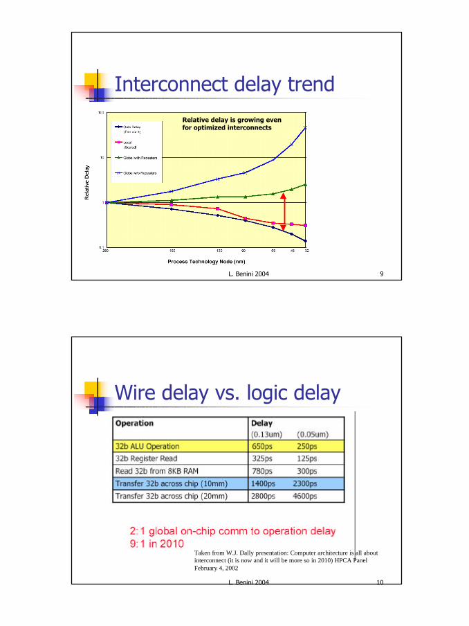
Interconnect delay trend
Relative delay is growing even for optimized interconnects
L. Benini 2004 10
Wire delay vs. logic delay
Taken from W.J. Dally presentation: Computer architecture is all about interconnect (it is now and it will be more so in 2010) HPCA Panel February 4, 2002
6
L. Benini 2004 11
Communication Reliability
n Information transfer is inherently unreliable at the electrical level, due to:n Timing errorsn Cross-talkn Electro-magnetic interference (EMI)n Soft errors
n The problem will get increasingly more acute as technology scales down
0.2 um1.0 umCc
CcCs Cs
L. Benini 2004 12
Noise and transient errorsn SoC will operate in presence of noise
n Data may be delayed or corruptedn Malfunctions modeled as single/multiple upsets
n Future methods must tolerate noisen Push solution to higher abstraction levels
7
L. Benini 2004 13
Outline
n Introduction and motivationn Physical limitations of on-chip interconnectn Communication-centric design
n On-chip networks and protocolsn Software aspects of on-chip networks
L. Benini 2004 14
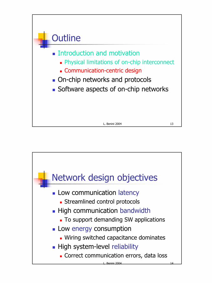
Network design objectives
n Low communication latencyn Streamlined control protocols
n High communication bandwidthn To support demanding SW applications
n Low energy consumptionn Wiring switched capacitance dominates
n High system-level reliabilityn Correct communication errors, data loss
8
L. Benini 2004 15
Theme 1: QoS or Best effort?n Essential to recover global predictability
n NOTE: pplications require itn It fits well with protocol stack concept
n What is QoS?– Requester poses the service request (negotiation)n Provider either commit to or reject your request– renegotiate when requirements change
n After negotiation. steady states that are predictable
(re)negotiatesteady states
L. Benini 2004 16
The cost of QoSn Best-effort services have better average resource utilisation at the cost of unpredictable/unbounded worst-case behaviourn The combination of best-effort & guaranteed services (c) is useful!
9
L. Benini 2004 17
Theme 2: Modularity vs. efficiency
n Bus-Centric Protocol Interface:n Forces core interface to the specs of a particular bus
n Core-Centric Protocol Interface:n Provides an abstract communication channel for the coren Enables unconstrained interface bridge to any
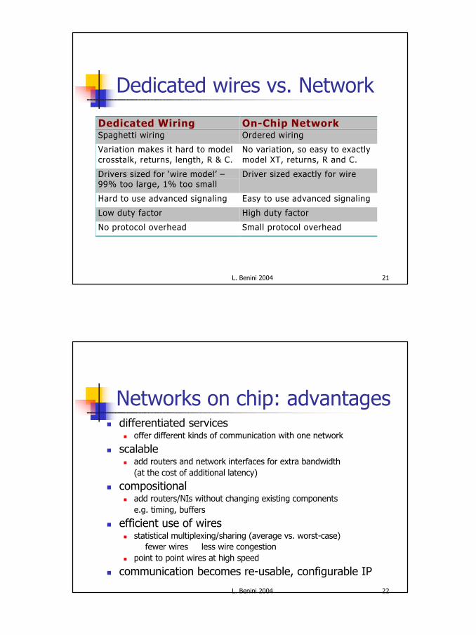
Variation makes it hard to modelcrosstalk, returns, length, R & C.
No variation, so easy to exactlymodel XT, returns, R and C.
Drivers sized for ‘wire model’ –99% too large, 1% too small
Driver sized exactly for wire
Hard to use advanced signaling Easy to use advanced signaling
Low duty factor High duty factor
No protocol overhead Small protocol overhead
L. Benini 2004 22
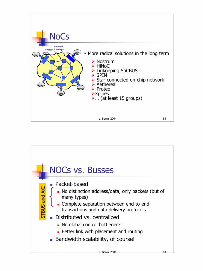
Networks on chip: advantagesn differentiated services
n offer different kinds of communication with one network
n scalablen add routers and network interfaces for extra bandwidth
(at the cost of additional latency)
n compositionaln add routers/NIs without changing existing components
e.g. timing, buffers
n efficient use of wiresn statistical multiplexing/sharing (average vs. worst-case)
⇒ fewer wires ⇒ less wire congestionn point to point wires at high speed
n communication becomes re-usable, configurable IP
12
L. Benini 2004 23
Outline
n Introduction and motivationn Physical limitations of on-chip interconnectn Communication-centric design
n On-chip networks and protocolsn Designing NoCsn NoCs case studies
n Software aspects of on-chip networks
L. Benini 2004 24
Outline
n Introduction and motivationn Physical limitations of on-chip interconnectn Communication-centric design
n On-chip networks and protocolsn Designing NoCsn NoCs case studies
n Software aspects of on-chip networks
13
L. Benini 2004 25
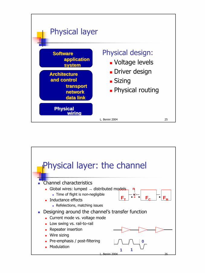
Physical layer
Physical design:n Voltage levelsn Driver designn Sizingn Physical routing
applicationapplicationsystemsystem
SoftwareSoftware
ArchitectureArchitectureand controland control
transporttransportnetworknetworkdata linkdata link
wiringwiringPhysicalPhysical
L. Benini 2004 26
Physical layer: the channel
n Channel characteristicsn Global wires: lumped → distributed models
n Time of flight is non-negligible
n Inductance effectsn Refelections, matching issues
n Designing around the channel’s transfer functionn Current mode vs. voltage mode n Low swing vs. rail-to-railn Repeater insertionn Wire sizingn Pre-emphasis / post-filteringn Modulation
FCFT FR+
n
11 11
00
14
L. Benini 2004 27
Low Swing signalling circuit
n Pseudodifferential interconnect [Zhang et al., JSSC00] (x6 energy reduction vs. CMOS Vdd=2V)
Static FF
Clocked SA
Low Vdd reference (0.5V)
L. Benini 2004 28
Physical layer: synchronization
n Single, global timing reference is not realisticn Direct consequence of non-negligible tofn Isochronous regions are shrinking
n How and when to sample the channel?n Avoid a clock: asyncronous communicationn The clock travels with the datan The clock can be reconstructed from the data
n Synchronization recovery has a costn Cannot be abstracted awayn Can cause errors (e.g., metastability)
B1…Bn
CLK
D Q
CK
0
12
15
L. Benini 2004 29
Case study: Asyncronous Busn MARBLE SoC Bus
n 1-of-4 encoding (4 wires for 2 bits)n Delay insensitive - No bus clock - Wire pipeliningn High crosstalk immunityn Four-phase ACK protocol
00 01 10 11
L1
L2
L3
L4
L. Benini 2004 30
Architecture and control
applicationapplicationsystemsystem
SoftwareSoftware
ArchitectureArchitectureand controland control
transporttransportnetworknetworkdata linkdata link
wiringwiringPhysicalPhysical
16
L. Benini 2004 31
Data link layer
n Provide reliable data transfer on an unreliable physical channel
n Access to the communication mediumn Dealing with contention and arbitration
n Issuesn Fairness and safe communicationn Achieve high throughputn Error resiliency
L. Benini 2004 32
ICACHE MEM.CTRL.AMBA BUSINTERFACE
FROM EXT.
MEMORY
HRDATA AMBA BUS
• Compare original AMBA bus toextended bus with error detection and correction or retransmission– SEC coding– SEC-DED coding– ED coding
• Explore energy efficiency
Data-link protocol example:error-resilient coding
H DECODER H ENCODER
MTTF
17
L. Benini 2004 33
Network layer: topology
n Buses:n Pro: simple, existing standardsn Contra: performance, energy-efficiency, arbitration
n Other network topologies:n Pro: higher performance, experience with MPn Contra: physical routing, need for network and transport
layers
Challenge: exploit appropriate network architecture and corresponding protocols
L. Benini 2004 34
Multiple Bussesn Simple way to increase bandwidth
n use more than one busn Can be static or dynamic assignment to busses
n staticn A->B always uses bus 0n C-> always uses bus 1
n dynamicn arbitrate for a bus, like instruction dispatch to k identical CPU resources
SC RS SC RS
MM MMPC PC
P P
PC PC
P P
Global bus
Local busLocal bus
Sharedcache
MainMemory
Routingswitch
processor
privatecache
18
L. Benini 2004 35
Crossbar
n No bandwidth reduction n (except receiver at endoint)
n Easy routing (on or offline)n Scales poorly
n N2 area and delay
n No locality
L. Benini 2004 36
Hypercube (direct)n Arrange 2n nodes in n-dimensional cuben At most n hops from source to sink
n log(number of nodes)n High bisection bandwidth
n good for traffic (but can you use it?)n bad for cost [O(n2)]
n Exploit localityn Node size grows
n as log(N) [IO]n Maybe log2(N) [xbar between dimensions]
0-D 1-D 2-D 3-D 4-D
19
L. Benini 2004 37
Multistage (indirect)n Unroll hypercube vertices so log(N), constant size
switches per hypercube noden solve node growth problemn lose localityn can be blocking, but it can be made non-blocking with more
stages
L. Benini 2004 38
K-ary N-cuben Alternate reduction from hypercube
n restrict to N<log(N) dimensional structuren allow more than 2 ordinates in each dimension
n E.g. mesh (2-cube), 3D-mesh (3-cube)n Matches with physical world structuren Bounds degree at noden Has Localityn Even more bottleneck potentials
2D Mesh
20
L. Benini 2004 39
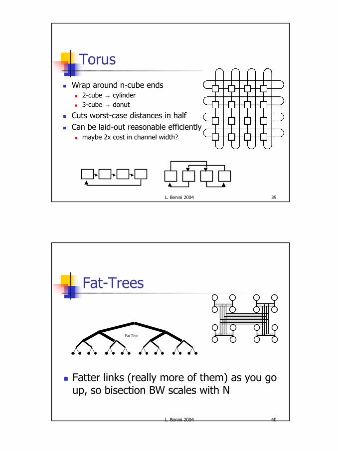
Torus
n Wrap around n-cube endsn 2-cube → cylindern 3-cube → donut
n Cuts worst-case distances in halfn Can be laid-out reasonable efficiently
n maybe 2x cost in channel width?
L. Benini 2004 40
Fat-Trees
n Fatter links (really more of them) as you go up, so bisection BW scales with N
Fat Tree
21
L. Benini 2004 41
Network layer: controln Switching
n Connection-oriented switchingn A path from source to destination is reserved prior to communicationn Useful for traffic with infrequent and long messagesn Circuit switching, virtual circuits
n Connection-less switchingn The communication path is determined dynamicallyn Datagram
n Routingn Unicast, multicastn Source routing, distributed routingn Deterministic, adaptive
Challenge: which models and what parameter valuesare effective for on-chip communication?
L. Benini 2004 42
Connection-oriented schemesn Communication path is fixed before data transmission startsn Network types: circuit switched, virtual circuit
n Basic operationsn Connection setupn Data transfern Connection teardown
n Advantagesn QoS (e.g. bandwidth, delay, jitter) guarantee through resource
reservation over the fixed pathn Suited to real-time, constant BW communication
n Disadvantagesn Resource utilization is worse than connection-less communication (i.e.
datagram).n Connection setup overhead
22
L. Benini 2004 43
Connection-less schemesn Communication path is determined dynamically
during data (packet) transmission
n Network type: datagramn Advantages
n Better adaptation to the varying network trafficn Better utilization of network resourcen Suited to variable bit rate communication
n (e.g. encoded voice, MPEG2,4, etc.)
n Disadvantagen Poor QoS support (ß no resource reservation)
Time
L. Benini 2004 44
Packet-based communication:Virtual circuit
n Fixed end-to-end communication pathn Packets are transferred over the VC
n QoS guarantee:n Through resource reservation when the
connection is set up
VC1
VC2
Each link can be shared by several VC’s
* Multiplexing on each link
23
L. Benini 2004 45
Packet-based communication: Datagram
n Connection-lessn Routers route packets independently.
n Packets can take any paths to the destination.
n Routers manage routing tables to find paths to destinationsn Non-deterministic communication delay due to
communication resource (buffer and link) contentionn No QoS guarantee!n Flow and congestion control is needed
Dest
Src
Packet #1Packet #2
L. Benini 2004 46
Packet Forwarding Schemesn Store-and-forward
n Virtual-cut-through
(1) After A finishes receiving the entire packet,A asks B if B is ready for the entire packet.
(2) B à A, ack(3) A sends the packet to B.
A B
(1) While A receives a part of the packet, A asks B if B is ready for the entire packet.
(2) B à A, ack(3) A starts to send the packet to B
even when A has not yet received the entire packet.
A B Pipelining!
The samebuffer spaceis needed
24
L. Benini 2004 47
Packet Forwarding Schemes II
(1) After A receives a flit of the packet, A asks B if B is ready to receive a flit
(2) B à A, ack(3) A sends a flit to B.
A BPipeliningon a flit (flow control unit)basis
flit size < packet sizeSmaller data spaceis needed thanstore-and-forward
A B C
D Head-of-lineblocking problem
Packets cannot pass from D to Edue to the blocked link between A and B
E
XC cannot send itand has no enough space for a new flit
Blocked!BlockedBlocked
n Wormhole
L. Benini 2004 48
AB
Virtual Channels
n Performance improvement using virtual channels
Node 1 Node 2 Node 3 Node 4 Node 5Destination of B
Block
Node 1 Node 2 Node 3 Node 4 Node 5Destination of B
25
L. Benini 2004 49
Transport layer
n Decompose and reconstruct information n Important choices
n Packet granularityn Admission/congestion controln Packet retransmission parameters
n All these factors affect heavily energy and performance
n Application-specific schemes vs. standards
L. Benini 2004 50
Benefits of packets
n Reliable error-control mechanism n With small overhead
n Exploit different routing pathsn Spread information to avoid congestion
n Several user-controllable parametersn Size, retransmission schemes, …
n Use retransmission rate for calibrating parameters
26
L. Benini 2004 51
Software layers
n System softwaren OS, RTOS, run-time
schedulern Component and
network dependent
n Application softwaren User and standard
applications
applicationapplicationsystemsystem
SoftwareSoftware
ArchitectureArchitectureand controland control
transporttransportnetworknetworkdata linkdata link
n The initiator/target side of the bus interfacen Arbiter
n Controls the access to the busn Bridge
n Connects two buses n It acts as an initiator on one side and a target on the other
Bus actors
30
L. Benini 2004 59
AHB Bus architecture
Different wires⇒No bidirectional wires
L. Benini 2004 60
AMBA basic transfer
For a write
For a read
31
L. Benini 2004 61
Transfer with WAIT states
2 wait cycles
L. Benini 2004 62
Bus Arbitration
n Buses can support multiple initiatorsn Need a protocol for allocating bus
resources and resolving conflicts n Bus arbitration
n Need a decision procedure to choosen Arbitration policy
NOTE: Do not confuse Arbitration Protocol with arbitration policy
32
L. Benini 2004 63
Granting bus access
Waiting for access
L. Benini 2004 64
Burst transfers
n Arbitration has a significant costn Burst transfers amortize arbitration cost
n Grant bus control for a number of cyclesn Help with DMA and block transfers
n Requires safeguards against starvation
33
L. Benini 2004 65
Critical analysis: bottlenecks
n Protocoln Lacks parallelism
n In order completionn No multiple outstanding transactions: cannot hide slave wait states
n High arbitration overhead (on single-transfers)n Bus-centric vs. transaction-centric
n Initiators and targets are exposed to bus architecture (e.g. arbiter)
n Topologyn Scalability limitation of shared bus solution!
L. Benini 2004 66
STBUS
n On-chip interconnect solution by STn Level 1-3: increasing complexity (and performance)
n Featuresn Higher parallelism: 2 channels (M-S and S-M)n Multiple outstanding transactions with out-of order completionn Supports deep pipeliningn Supports Packets (request and response) for multiple data transfersn Support for protection, caches, locking
n Deployed in a number of large-scale SoCs in STM
34
L. Benini 2004 67
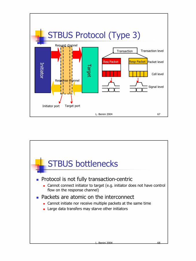
STBUS Protocol (Type 3)
TargetInitiator port Target port
Initiator
Request channel
Response channel
Transaction
Req Packet Resp Packet
Cell level
Packet level
Transaction level
Signal level
L. Benini 2004 68
STBUS bottlenecks
n Protocol is not fully transaction-centricn Cannot connect initiator to target (e.g. initiator does not have control
flow on the response channel)
n Packets are atomic on the interconnectn Cannot initiate nor receive multiple packets at the same timen Large data transfers may starve other initiators
35
L. Benini 2004 69
AMBA AXI
n Latest (2003) evolution of AMBAn Advanced eXtensible Interface
n Featuresn Fully transaction centric: can connect M to S with nothing in betweenn Higher parallelism: multiple channelsn Supports bus-based power managementn Support for protection, caches, locking
n Deployment: ??
L. Benini 2004 70
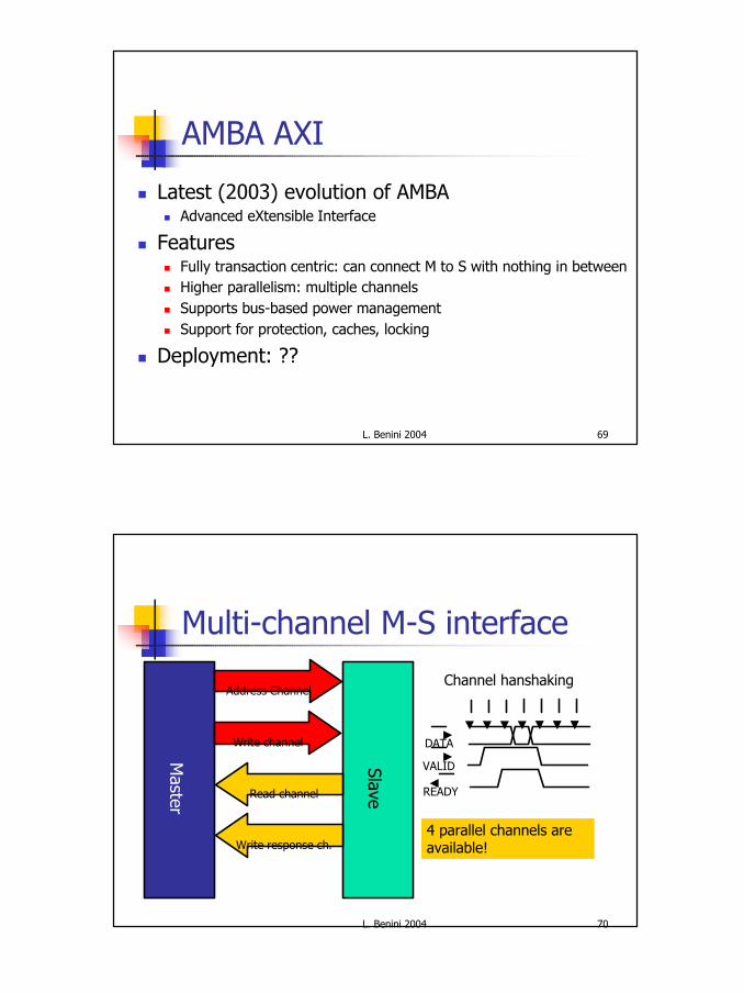
Multi-channel M-S interface
Master
Slave
Address Channel
Write channel
Read channel
Write response ch.
VALID
DATA
READY
Channel hanshaking
4 parallel channels are available!
36
L. Benini 2004 71
Multiple outstanding transactions
n A transaction implies activity on multiple channelsn E.g Read uses the Address and Read channel
n Channels are fully decoupled in timen Each transaction is labeled when it is started (Address channel)n Labels, not signals, are used to track transaction opening and closingn Out of order completion is supported (tracking logic in master),
but master can request in order delivery
n Burst supportn Single-address burst transactions (multiple data channel slots)n Bursts are not atomic!
n Atomicity is trickyn Exclusive access better than locked access
L. Benini 2004 72
Scalability: Execution Time
n Highly parallel benchmark (no slave bottlenecks)
AHB AXI STBus STBus (B)
0%
10%
20%
30%
40%
50%
60%
70%
80%
90%
100%
110%
2 Cores
4 Cores
6 Cores
8 Cores
Rel
ativ
e ex
ecut
ion
tim
e
AHB AXI STBus STBus (B)
0%10%20%30%40%50%60%70%80%90%
100%
110%120%130%140%
150%160%170%
180%
2 Cores
4 Cores
6 Cores
8 Cores
Rel
ativ
e ex
ecut
ion
tim
e
§ 1 kB cache (low bus traffic)
§ 256 B cache (high bus traffic)
37
L. Benini 2004 73
Scalability: Protocol Efficiency
AHB AXI STBus STBus (B)
0%
10%
20%
30%
40%
50%
60%
70%
80%
90%
100%
2 Cores
4 Cores
6 Cores
8 Cores
Inte
rcon
nect
usa
ge e
ffic
ienc
y
AHB AXI STBus STBus (B)
0%
10%
20%
30%
40%
50%
60%
70%
80%
90%
100%
2 Cores
4 Cores6 Cores
8 Cores
Inte
rcon
nect
bus
y
n Increasing contention: AXI, STBus show 80%+ efficiency, AHB < 50%
n Fast and predictable interconnectn Very simple and fast routing
n Guaranteed QoS: deterministic scheduling, no contentionn Flexible
n Runtime reconfiguration of cores and interconnect
n Power consumptionn Implement power saving features in both cores and interconnectn Use reconfiguration to dynamically control power consumption
49
L. Benini 2004 97
aSoC: adaptive System on a Chipn Tiled SoC architecturen More than one tile can be
allocated to a single coren Direct network
n Near neighbor communication
n Routing logic in corners
DCT
VLE
MemoryViterbiFIR
EncryptControl
Motion Estimationand Compensation
L. Benini 2004 98
Example: StreamStream A-D
CBA
West to Core
1
3
2
Core to East
West to EastLoopBack
50
L. Benini 2004 99
Critical analysisn Tile-based architecture not well-suited
to heterogeneous platformsn Static scheduling implies very rigid
communication patternsn Underutilization of resourcesn Sporadic traffic is hard
n Not really for general purpose computation & communication
L. Benini 2004 100
Æthereal: contextn Consumer electronics
n reliability & predictability are essentialn low cost is crucialn time to market must be reduced
n NoC offer differentiated servicesn to manage (and hence reduce) resourcesn to ease integration (and hence decrease TTM)
51
L. Benini 2004 101
Æthereal: featuresn Conceptually, two disjoint networks
n a network with throughput+latency guarantees (GT)n a network without those guarantees (best-effort, BE)
n Several types of commitment in the networkn combine guaranteed worst-case behaviour
with good average resource usage
priority/arbitration
best-effortrouter
guaranteedrouter
programming
L. Benini 2004 102
Router architecturen Best-effort router
n Worm-hole routingn Input queueingn Source routing
n Guaranteed throughput routern Contention-free routing
n synchronous, using slot tablesn time-division multiplexed circuits
n Store-and-forward routingn Headerless packets
n information is present in slot table
52
L. Benini 2004 103
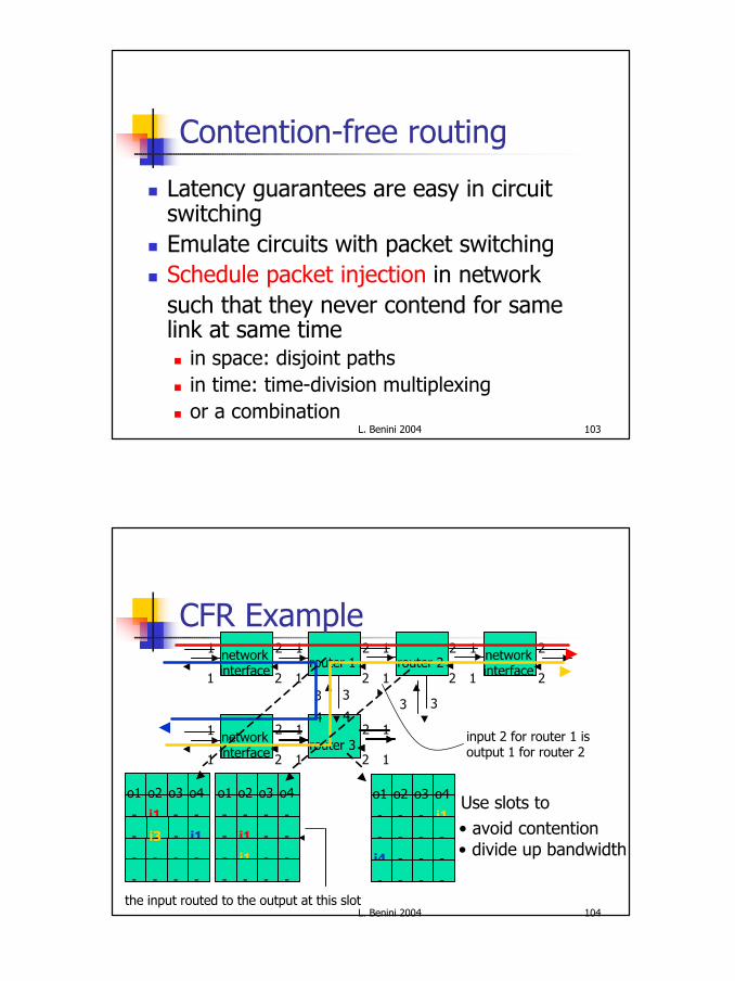
Contention-free routing
n Latency guarantees are easy in circuit switching
n Emulate circuits with packet switchingn Schedule packet injection in network
such that they never contend for same link at same timen in space: disjoint pathsn in time: time-division multiplexingn or a combination
L. Benini 2004 104
router 1
router 3
router 2networkinterface
networkinterface
networkinterface
1
1
2
1 2
1
3 3
input 2 for router 1 isoutput 1 for router 2
the input routed to the output at this slot
3 3
1
1
2
2
1
1
2
2
1
1
2
2
2
2
1
1
2
2
1
1
4 4
-
-
-
-
o1
-
i1
i1
-
o2
-
-
-
-
o3
-
-
-
-
o4
-
-
i4
-
o1
-
-
-
-
o2
-
-
-
-
o3
i1
-
-
-
o4 Use slots to• avoid contention• divide up bandwidth
-
-
-
-
o1
-
-
-
-
o3
-
i1
-
-
o4
i1
-
-
o2
i3
CFR Example
53
L. Benini 2004 105
CFR setupn Use best-effort packets to set up connections
n set-up & tear-down packets like in ATM (asynchronous transfer mode)
n Distributed, concurrent, pipelinedn Safe: always consistentn Compute slot assignment compile time, run time,
or combinationn Connection opening is guaranteed to complete
(but without a latency guarantee)with commitment or rejection
L. Benini 2004 106
Router implementation
n Memories (for packet storage)n Register-based FIFOs are expensiven RAM-based FIFOs are as expensive
n 80% of router is memory
n Special hardware FIFOs are very usefuln 20% of router is memory
n Speed of memoriesn registers are fast enoughn RAMs may be too slown Hardware FIFOs are fast enough
iqu iqu
iquiqu
switch
iqu
iqu
msu
stu
routers based onregister-file and hardware fifos
drawn to approximatelysame scale (1mm2, 0.26mm2)
54
L. Benini 2004 107
Layout
…
X
BQ
GQ
…
slot table arbiter
reconfiguration logic
programmingpackets
BQ
GQ flowcontrol
datapackets
BQ
GQ
L. Benini 2004 108
Resultsn 5 input and 5 output ports (arity 5)n 0.25 mm2 CMOS12n 500 MHz data path, 166 MHz control pathn flit size of 3 words of 32 bitsn 500x32 = 16 Gb/s throughput per link, in each directionn 256 slots & 5x1 flit fifos for guaranteed-throughput trafficn 6x8 flit fifos for best-effort traffic
55
L. Benini 2004 109
Xpipes: contextn Typical applications targeted by SoCs
n Complexn Highly heterogeneous (component specialization)n Communication intensive
n Xpipes is a synthesizable, high performance, heterogeneous NoC infrastructure
Task1 Task2 Task4
Task3
SB
Task5
P1(T1) P4(T4)
P3(T3) P5(T5)
NI
NINI
NI
L1
Application mapping(custom, domain-specific)
L. Benini 2004 110
Heterogeneous topology
SoC component specialization leads to the integration of heterogeneous cores
Ex. MPEG4 Decoder
§ Non-uniform block sizes§ SDRAM: communication
bottleneck§ Many neighboring cores
do not communicate
§ Risk of under-utilizing many tiles and links§ Risk of localized congestion
On a homogeneous fabric:
56
L. Benini 2004 111
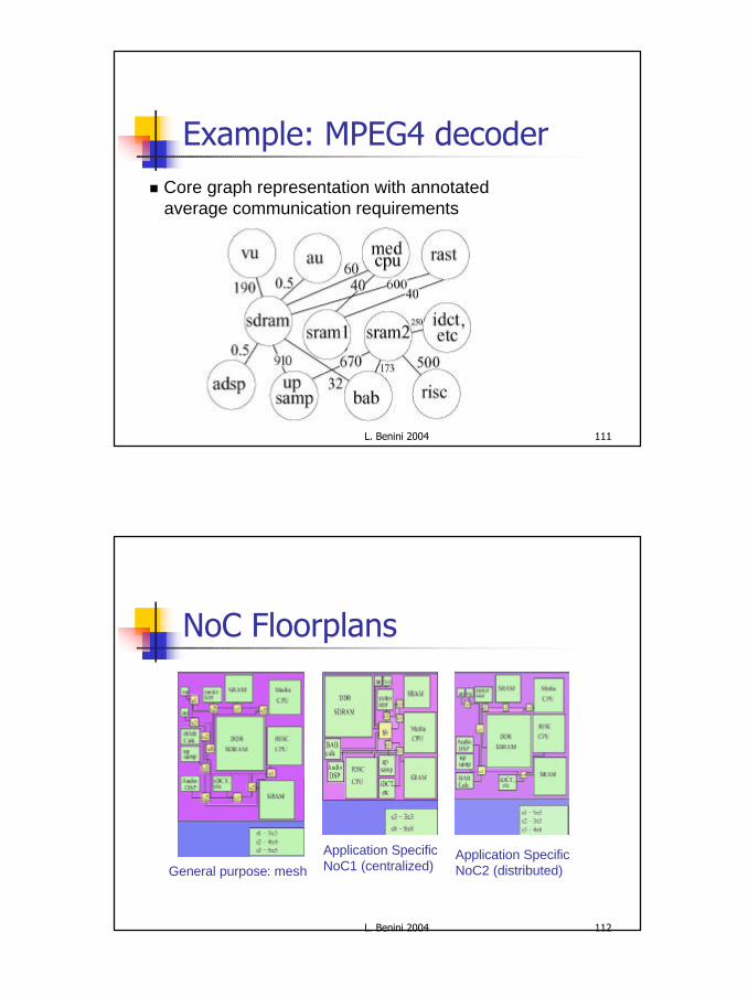
Example: MPEG4 decoder n Core graph representation with annotated
average communication requirements
L. Benini 2004 112
NoC Floorplans
General purpose: mesh
Application Specific NoC1 (centralized)
Application Specific NoC2 (distributed)
57
L. Benini 2004 113
Performance, area and power
n Relative link utilization(customNoC/meshNoC):1.5, 1.55
n Relative area(meshNoC/customNoC):1.52, 1.85
n Relative power(meshNoC/customNoC):1.03, 1.22
Less latency and betterScalability of custom NoCs
L. Benini 2004 114
Xpipes: featuresn Source based routing
n Very high performance switch designn Wormhole switching
n Minimize buffering area while reducing latencyn Pipelined links
nLink data introduction interval is not bound by wire delaynLink-latency (# of repeater stages) insensitive operation
n Parameterizable network building blocks nPlug-and-play composable for arbitrary network topologynDesign time tunable buffer size, link width, virtual channels, # of switch I/Os
n Standard OCP interface
58
L. Benini 2004 115
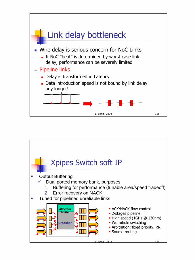
Link delay bottleneck
n Wire delay is serious concern for NoC Linksn If NoC “beat” is determined by worst case link
delay, performance can be severely limited
ð Pipeline linksn Delay is transformed in Latencyn Data introduction speed is not bound by link delay
any longer!L
L. Benini 2004 116
Xpipes Switch soft IP
Crossbar
AllocatorArbiter
§ Output Bufferingü Dual ported memory bank, purposes:
1. Buffering for performance (tunable area/speed tradeoff)2. Error recovery on NACK
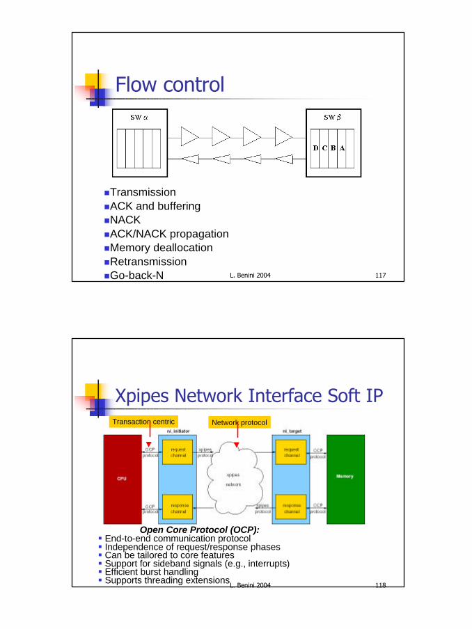
Open Core Protocol (OCP):§ End-to-end communication protocol § Independence of request/response phases§ Can be tailored to core features§ Support for sideband signals (e.g., interrupts)§ Efficient burst handling§ Supports threading extensions
60
L. Benini 2004 119
Xpipes packeting mechanismHeader register (about 50 bits): one for every transaction
OCPfrom MAddr, after LUT
Flit decomposition
OCP
Payload register: one for every burst beat
1st beatof a burst read
Flit decomposition
L. Benini 2004 120
Xpipes design challenges
n The fight against latency: multi-hop topologies are at a disadvantagen Low number of stages per hopn Overclock the network
n Minimize the price for flexibilityn Synthesis-aware designn Use specialized leaf cells
61
L. Benini 2004 121
NoCs at work: cross-benchmarking
AMBA Topologies
P0 P1 P2 P8
M0 M1 M2 M8
Shared bus Multilayer (crossbar)
A B C
Processors
Private memories Shared slaves
P0
P1
P2
P8
AH
BIn
terC
on
nec
tM
atri
x(I
CM
)
M0
M1
M2
M8
A
B
C
L. Benini 2004 122
Topologies under testXpipes topologies
Crossbar-like Mesh
P0
P1
P2
P8
M0
M1
M2
M8
A B C
19x19 single switch
P0
M0
P1
M1 M2 M3
M4 M5 M6 M7
A B C
P2 P3
P4 P5 P6 P7
62
L. Benini 2004 123
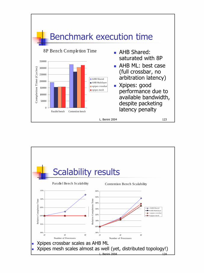
Benchmark execution time
n AHB Shared: saturated with 8P
n AHB ML: best case (full crossbar, no arbitration latency)
n Xpipes: goodperformance due to available bandwidth,despite packeting latency penalty
8P Bench Comple tion Time
0
50000
100000
150000
200000
250000
300000
350000
Parallel bench Contention bench
Co
mp
leti
on
Tim
e (C
ycl
es)
AHB Shared
AHB Multilayer
xpipes crossbar
xpipes mesh
L. Benini 2004 124
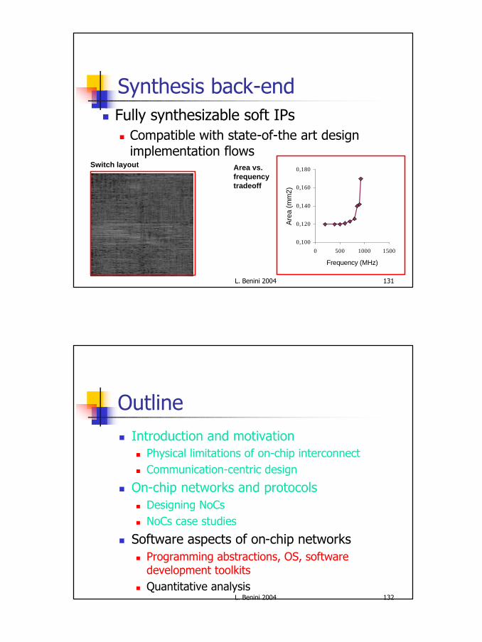
Scalability resultsParalle l Bench Scalability
90%
95%
100%
105%
110%
115%
2P 4P 8P
Number of Processors
Rel
ativ
e C
ompl
etio
n T
ime
AHB Shared
AHB Multilayer
xpipes crossbar
xpipes mesh
Contention Bench Scalability
90%
100%
110%
120%
130%
140%
150%
160%
2P 4P 8P
Number of Processors
Rel
ativ
e C
ompl
etio
n T
ime
AHB Shared
AHB Multilayer
xpipes crossbar
xpipes mesh
n Xpipes crossbar scales as AHB MLn Xpipes mesh scales almost as well (yet, distributed topology!)
63
L. Benini 2004 125
Latency analysis
n Burst reads: to private memories
n Xpipes latency is the target forperformance optimization!!
Contention Bench Burs t Read Latency
0
5
10
15
20
25
30
35
40
45
2P 4P 8P
Number of Processors
Bur
st R
ead
Lat
ency
(cy
cles
)
AHB Shared
AHB Multilayer
xpipes crossbarxpipes mesh
L. Benini 2004 126
Latency analysis
n Single reads: toshared memoryn Xpipes meshscales worse thanthe crossbar dueto link congestionand more hops
Contention Bench Single Read Late ncy
0
5
10
15
20
25
30
35
40
45
50
2P 4P 8P
Number of Processors
Sin
gle
Rea
d L
aten
cy (
cycl
es)
AHB Shared
AHB Multilayer
xpipes crossbar
xpipes mesh
64
L. Benini 2004 127
Xpipes area/frequency
0
0,05
0,1
0,15
0,2
0,25
0,3
0,35
0,4
0,45
16 32 64 128
Flit width
Are
a (m
m2) Initiator NI
Target NI
4x4 switch
6x4 switch
A 3x4 Xpipes mesh with 8 processors and 11 slavesconsumes ~2,6 mm2
0.13 um technology, 4-flit output buffers§ Initiator NI:
1 GHz
§ Target NI:1 GHz
§ 4x4 switch:1 GHz
§ 6x4 switch:875-980 MHz
L. Benini 2004 128
NoC synthesis flow
In cooperation with Stanford Univ.
SUNMAP
Power Lib
Area Lib
Floor-planner
xpipesLibrary
xpipesCompiler
SystemCDesign
Simu-lation
MappingOnto
TopologiesTopologySelection
TopologyLibrary
RoutingFunction
Co-Design
Appln
65
L. Benini 2004 129
Topology mapping (SUNMAP)
Heuristic approach with several phases
Initial mapping using a greedy algorithm (from communication graph)
§ Parsing specification (tree structure)§ Create a class template for each type of network component§ Components optimizations (I/O ports, buffer sizing)§ Hierarchical instantiation of the system (sc_main)§Synthesis view§Simulation view
66
L. Benini 2004 131
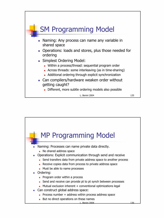
Synthesis back-endn Fully synthesizable soft IPs
n Compatible with state-of-the art design implementation flows
Switch layout
0,100
0,120
0,140
0,160
0,180
0 500 1000 1500
Frequency (MHz)
Are
a (m
m2)
Area vs. frequencytradeoff
L. Benini 2004 132
Outlinen Introduction and motivation
n Physical limitations of on-chip interconnectn Communication-centric design
n On-chip networks and protocolsn Designing NoCsn NoCs case studies
n Software aspects of on-chip networksn Programming abstractions, OS, software
development toolkitsn Quantitative analysis
67
L. Benini 2004 133
Programming for NoCs
n The programmer modeln Sequential: no parallelism is exposed to the
programmern Parallel: multiple threads/tasks
n Shared memory: communication is “implied” by shared memory access
n Message passing: communication is explicit in messages
n Parallelism extraction vs. parallelism support
L. Benini 2004 134
Sequential Programming Modeln Naming: Can name any variable ( in virtual address
space)n Hardware (and perhaps compilers) does translation to physical
addresses
n Operations: Loads, Stores, Arithmetic, Controln Ordering: Sequential program ordern Performance Optimizations
n Compilers and hardware violate program order without getting caughtn Compiler: reordering and register allocationn Hardware: out of order, pipeline bypassing, write buffers
n Retain dependence order on each “location”n Transparent replication in caches
68
L. Benini 2004 135
SM Programming Modeln Naming: Any process can name any variable in
shared spacen Operations: loads and stores, plus those needed for
orderingn Simplest Ordering Model:
n Within a process/thread: sequential program ordern Across threads: some interleaving (as in time-sharing)n Additional ordering through explicit synchronization
n Can compilers/hardware weaken order without getting caught?n Different, more subtle ordering models also possible
L. Benini 2004 136
MP Programming Modeln Naming: Processes can name private data directly.
n No shared address spacen Operations: Explicit communication through send and receive
n Send transfers data from private address space to another processn Receive copies data from process to private address space
n Must be able to name processesn Ordering:
n Program order within a processn Send and receive can provide pt to pt synch between processes
n Mutual exclusion inherent + conventional optimizations legaln Can construct global address space:
n Process number + address within process address spacen But no direct operations on these names
69
L. Benini 2004 137
The Case for Message Passingn MP exposes communication
n Eases taking into account communication costs at the application level
n Better control and predictability
n MP is scalablen Current specification styles (e.g., DSP) match
MP abstractionn Achieves higher performancen Programming/porting harder starting from
single-thread computation
L. Benini 2004 138
NoC Message PassingApplications
Abstract Parallel architecture
T1T1
T2T2 T3T3
BB
EE
PEPE
PEPE
NoC
PEPE
MM
MM
IOIO
n How much HW detail?n E.g. exposing network latency?
n How much control?n E.g. Guaranteed QoS of Best
effort?
n Implicit vs. explicit trafficn E.g. Instruction cache misses
70
L. Benini 2004 139
Middlewaren Traditional RTOSes
n Single-processor mastern Limited support for complex memory hierarchiesn Focused on performance
n The NoC Middlewaren Natively parallel & scalablen Supports heterogeneous memory, computation,
Static ApplicationsModule lib.Dynamic application set
L. Benini 2004 146
Outline
n Introduction and motivationn Physical limitations of on-chip interconnectn Communication-centric design
n On-chip networks and protocolsn Designing NoCsn NoCs case studies
n Software aspects of on-chip networksn Programming abstractions, OS, software
development toolkitsn Quantitative analysis
74
L. Benini 2004 147
Traffic Modeling
n Stochastic traffic modelsn Analytical distributionsn Easily parameterizable
n Trace-based modelsn Higher accuracyn Does not consider dynamic traffic-dependent effects (e.g. inter-processor communication)
n Functional trafficn Traffic directly generated by running applications n Requires OS support Complexity
Accuracy
Traditionally used traffic models trade-off accuracy with complexity:
L. Benini 2004 148
MPARM Architecture
INTERCONNECTION
ARM ARM INTERRUPTCONTROLLER
PRI MEM 4 SHARED MEM SEMAPHORES
ARM ARM
PRI MEM 3PRI MEM 2PRI MEM 1
STbusor AMBA or Xpipes
75
L. Benini 2004 149
Approach to design space analysis
§ Exploring of meaningful points in the design spaceØ Modelling accuracy emphasized
§ Power and performance analysis for different:Ø Classes of applications (computation vs communication dominated)Ø Software architectures (stand-alone vs OS supported appln)Ø System configurations (cache size, memory latency, ..)
Communication Architecture Design Space
Shared bus(AMBA) Evolutionary arch.
(STBUS)
Advanced NoC arch.(Xpipes)
L. Benini 2004 150
Latency breakdown
Sender
Receiver
SenderOverhead
Transmission time(size ÷ bandwidth)
Transmission time(size ÷ bandwidth)
Time ofFlight
ReceiverOverhead
Transport Latency
Total Latency = Sender Overhead + Time of Flight + Message Size ÷ BW + Receiver Overhead
Total Latency
(processorbusy)
(processorbusy)
76
L. Benini 2004 151
Basic architecture
MMUI/D Cache
INT
ER
CO
NN
EC
TIO
N
ARM Core
SH
AR
ED
M
EM
Processor tile#1
SE
MA
PH
OR
ES
MMUI/D Cache
ARM Core
Processor tile#N
Producer
Consumer
L. Benini 2004 152
Support for message passing
MMU
I/D Cache
SPM
INT
ER
CO
NN
EC
TIO
N
ARM Core
SH
AR
ED
M
EM
Processor tile#1
Semaphores
MMU
I/D Cache
SPM
ARM Core
Processor tile#2
Semaphores
Consumer
Producer
77
L. Benini 2004 153
HW support for MP: results
8 cores0.00%
25.00%
50.00%
75.00%
100.00%
125.00%
150.00%
175.00%
200.00%
225.00%
250.00%
275.00%
SharedBridgingMultiLayer
Rel
ativ
e ex
ecut
ion
tim
e
8 c o r e s0 .00%
10 .00%
20 .00%
30 .00%
40 .00%
50 .00%
60 .00%
70 .00%
80 .00%
90 .00%
1 0 0 . 0 0 %
1 1 0 . 0 0 %
1 2 0 . 0 0 %
S h a r e dBridgingMultiLayer
Rel
ativ
e ex
ecut
ion
tim
e
Matrix Pipeline with basic architectureMatrix Pipeline with message passing support
170%
20%
Send+Receive cost: 35KCycles (basic architecture) vs. 4KCycles (MP support)Configuration: 4 Processors, Shared bus
L. Benini 2004 154
ARM CoreARM CORE
Support for UMA
CACHE
BUS*
SNOOPDEVICE
Invalidate/Update
Address and Data
Processor tile#1
*cannot be a generic interconnect!
78
L. Benini 2004 155
Summary
n Paradigm shift towards NoCsn Designing NoCs
n Huge design spacen Unclear if there is a winnern Research will solidify soon
n Hardware/software interfaces is currently the main bottleneck