EINSTECHEN ABSTECHEN NUTFRÄSEN NUTSTOSSEN KOPIERFRÄSEN BOHREN REIBEN GROOVING PARTING OFF GROOVE MILLING BROACHING PROFILE MILLING DRILLING REAMING TECHNOLOGIEVORSPRUNG IST HORN HORN - LEADERS IN GROOVING TECHNOLOGY Verzahnungsfräsen bis Modul 6 Gear milling up to module 6 NEU NEW
Transcript
E I N S T E C H E N A B S T E C H E N N U T F R Ä S E N N U T S T O S S E N K O P I E R F R Ä S E N B O H R E N R E I B E N
G R O O V I N G P A R T I N G O F F G R O O V E M I L L I N G B R O A C H I N G P R O F I L E M I L L I N G D R I L L I N G R E A M I N G
TECHNOLOGIEVORSPRUNG IST HORNHORN - LEADERS IN GROOVING TECHNOLOGY
Verzahnungsfräsenbis Modul 6
Gear millingup to module 6
NEU NEW
Mit der Erweiterung der Verzahnungsfrässysteme bis Modul 6 bieten wir durchgängige Werkzeugsysteme für Modul 0,5 bis Modul 6. Das Verzahnungsprogramm umfasst das Fräsen von Stirnrädern, Fräsen von Welle-Nabe-Verbindungen, Stoßen von Innenverzahnungen, Fräsen von Schneckenwellen und das Fräsen kundenspezifischer Verzahnungsprofile.
Je nach Modulgröße (DIN 3972, Bezugsprofil 1) decken unter-schiedliche Frässysteme das Aufgabengebiet ab:
• Bis Modul 3: Schneidplatten Typ 606 bis 636 (auch als Dreischneider)• Bis Modul 4: Frässysteme M274 und M279 – einreihig und zweireihig für breite Profile• Bis Modul 6: das neue Frässystem Typ M121
Das Verzahnungsstoßen, sowohl von Innen- als auch von Außenverzahnungen in unterschiedlichen Verzahnungsgrößen, decken die Werkzeugsysteme Typ 105 und Typ 110 Supermini®, Typ S117 und Typ 315 ab. Das gleichzeitige Vor- und Fertigstoßen mit nur einer Schneidplatte verkürzt dabei die Taktzeiten erheblich.
With the expansion of the gear milling systems up to module 6, we offer integrated tool systems from module 0.5 to module 6. The gear range includes milling spur gears, milling shaft/hub connections, broaching internal toothing, milling worm shafts and milling customer-specific gear profiles.
Depending on the module size (DIN 3972, basic rack profile 1), there are various milling systems for the area of application:
• Up to module 3: Inserts of type 606 to 636 (also as triple cutters)• Up to module 4: M274 and M279 milling systems – single-row and two-row for wide profiles• The new M121 milling system up to module 6
Broaching toothing, both for internal and external toothing in various toothing sizes, is covered by the type 105 and type 110 Supermini®, plus type S117 and type 315 tool systems. Carrying out preliminary and final broaching work using just one insert significantly shortens cycle times.
Verzahnungsfräsenbis Modul 6
Gear millingup to module 6
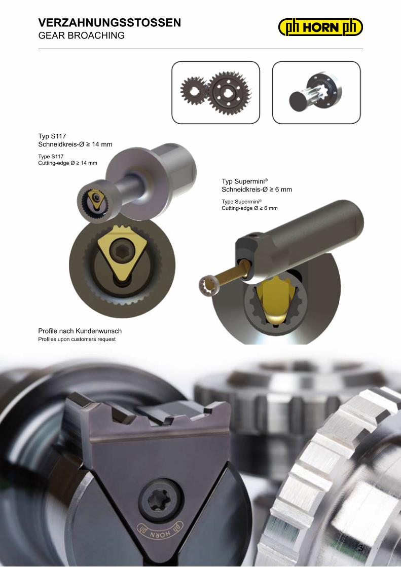
Profile nach KundenwunschProfiles upon customers request
VERZAHNUNGSSTOSSENGEAR BROACHING
Typ S117Schneidkreis-Ø ≥ 14 mm
Typ Supermini®Schneidkreis-Ø ≥ 6 mm
Type S117Cutting-edge Ø ≥ 14 mm
Type Supermini®Cutting-edge Ø ≥ 6 mm
3
Schneidplatte TypInserts type
Ds[mm]
Stirnräder / ZahnstangenBezugsprofil 1 nach
DIN 3972Cylindrical gears / Tooth barsBasic profile 1 according to
DIN 3972
Zahnwellen / Welle-Nabe / Kerbverzahnung
DIN 5480 / ANSI B92.1Gear shafts / Shaft-hub /
SerrationDIN 5480 / ANSI B92.1
606 11,7 mn ≤ 0,8 mn ≤ 1 / dB ≥ 40
608 15,7 mn ≤ 1 mn ≤ 1,5 / dB ≥ 40
611 17,7 mn ≤ 1,25 mn ≤ 2 / dB ≥ 40
613 21,7 mn ≤ 1,5 mn ≤ 3 / dB ≥ 22
628 27,7 mn ≤ 2 mn ≤ 2,5 / dB ≥ 40
632 31,7
mn ≤ 2,5 / Nr. 5 - 8
mn ≤ 2,5 / dB ≥ 30mn ≤ 2,25 / Nr. 2 - 8
mn ≤ 2 Nr. 1 - 8
635 34,7 mn ≤ 3 mn ≤ 5 / dB ≥ 50
636 35,7 mn ≤ 1,5 mn ≤ 2 / dB ≥ 60
VERZAHNUNGSFRÄSENGEAR MILLING
Fräsplatten für Stirnräder und ZahnwellenMilling inserts for spur gears and gear shafts
4
HM-SortenCarbide grades
BestellnummerPart number
ModulModule
z* E1 s Ds
MG
12
TN35
TI25
TA45
AS
45
613.3972.100.1 1 12 - 13
2,5 5,7 21,7
▲
613.3972.100.2 1 14 - 16 ▲
613.3972.100.3 1 17 - 20 ▲
613.3972.100.4 1 21 - 25 ▲
613.3972.100.5 1 26 - 34 ▲
613.3972.100.6 1 35 - 54 ▲
613.3972.100.7 1 55 - 134 ▲
613.3972.100.8 1 ≥ 135 Δ
613.3972.150.1 1,5 12 - 13 Δ
613.3972.150.2 1,5 14 - 16 ▲
613.3972.150.3 1,5 17 - 20 ▲
613.3972.150.4 1,5 21 - 25 ▲
613.3972.150.5 1,5 26 - 34 ▲
613.3972.150.6 1,5 35 - 54 Δ
613.3972.150.7 1,5 55 - 134 Δ
613.3972.150.8 1,5 ≥ 135 Δ
▲ ab Lager / on stock Δ 4 Wochen / 4 weeks P ●
● Haupteinsatzbereich / main recommendation M ●
ο bedingt einsetzbar / alternative recommendation K ●
███ unbeschichtete HM-Sorten / uncoated grades N ο
███ beschichtete HM-Sorten / coated grades S ●
███ bestückt/Cermet / brazed/Cermet H
Fräser-Nr.8 / Milling cutter N°8
Modul 1 / Module 1
DIN 3972Fräser Typ / Milling cutter type 613
Fräser-Nr.Milling cutter N°
*z (Zähnezahl Stirnrad)*z (N° of teeth cylindrical gear)
Zahnformfräser für Stirnräder mit Evolventenverzahnung nach DIN 867Bezugsprofil 1 nach DIN 3972 für FertigbearbeitungGear milling cutter for cylindrical gears with involuted flanks according to DIN 867Basic profile 1 according to DIN 3972 for finishing
Picture = right hand disc milling cutter RM274...S...
für Wendeschneidplattefor use with Indexable insert
TypType
VERZAHNUNGSFRÄSENGEAR MILLING
Schneidkreis-Ø Cutting edge Ø Ds 63/80/119 mm
S274
6
SchneidplatteTypInserts type
Ds[mm]
Stirnräder / ZahnstangenBezugsprofil 1 nach
DIN 3972Cylindrical gears / Tooth barsBasic profile 1 according to
DIN 3972
Zahnwellen DIN 5480 /ANSI B92.1Gear shaftsDIN 5480 /
ANSI B92.1
Schneckenwellen DIN 3975Worm shafts
DIN 3975
S274 ≥ 50 mn ≤ 2,3 mn ≤ 2,5 / dB ≥ 30 mx ≤ 2,3
S279 ≥ 100 mn ≤ 4 mn ≤ 4 / dB ≥ 50 mx ≤ 4Profile nach KundenwunschProfiles upon customers request
VERZAHNUNGSFRÄSEN bis Modul 4GEAR MILLING up to module 4
Ausführungen:- eine Schneidreihe- zwei Schneidreihen, einseitig verschraubt- zwei Schneidreihen, wechselseitig verschraubt
Execution:- one cutting serie- two cutting series, screwed single-sided- two cutting series, alternately screwed
7
Profile nach Kundenwunsch
Profilierungsbereich
Profiles upon customers request
Profiling range
D ZähnezahlN° of teeth
63 4
80 6
MESSERKOPF M121MILLING CUTTER M121
Für Verzahnungen bis Modul 6Bezugsprofil 1 nach DIN 3972 für FertigbearbeitungFor gearings up to module 6Basic profile 1 according to DIN 3972 for finishing