NEUTRAL BEAM TEST FACILITY (NBTF) TECHNICAL SUMMARY This document summaries the technical requirements relating to the Neutral Beam Test Facility. The Neutral Beam test Facility (NBTF), which is also called PRIMA (acronym for P adova R esearch on I TER M egavolt A ccelerator) consists of two separate development testbeds, ‐ the ion source test facility, called SPIDER (acronym for S ource for P roduction of I on of D euterium E xtracted from R f plasma) ‐ the megavolt test facility, called MITICA (acronym for M egavolt IT ER I njector & C oncept A dvancement). PRIMA will include the plant systems that are necessary to operate both the test beds. The NTBF will test all main aspects of the HNB system, except the components downstream of the HNB vessel (beamline exit scraper, fast shutter, absolute valve and duct liner). NTBF will include also substantial components from other DAs (IN, JA) and from the Host (Consorzio RFX) The design work for most of the components is done by EU on behalf of Iter Organization and is still in progress.
Transcript
NEUTRAL BEAM TEST FACILITY (NBTF) TECHNICAL SUMMARY
This document summaries the technical requirements relating to the Neutral Beam Test Facility.
The Neutral Beam test Facility (NBTF), which is also called PRIMA (acronym for Padova Research on ITER Megavolt Accelerator) consists of two separate development testbeds,
‐ the ion source test facility, called SPIDER (acronym for Source for Production of Ion of Deuterium Extracted from Rf plasma)
‐ the megavolt test facility, called MITICA (acronym for Megavolt ITER Injector & Concept Advancement).
PRIMA will include the plant systems that are necessary to operate both the test beds.
The NTBF will test all main aspects of the HNB system, except the components downstream of the HNB vessel (beamline exit scraper, fast shutter, absolute valve and duct liner).
NTBF will include also substantial components from other DAs (IN, JA) and from the Host (Consorzio RFX)
The design work for most of the components is done by EU on behalf of Iter Organization and is still in progress.
Overall breakdown
The following is a list of the major equipment that will be purchased by F4E for the NBTF.
Description Specifications
MITICA Beam Line Components Build to printMITICA Cryogenic Plant FunctionalMITICA Beam Source Build to printMITICA Vessel Build to printMITICA Cryopump Build to printPRIMA Vacuum & Gas Injection Plants FunctionalMITICA RMFCs Build to print
Where the specifications are drafted at a functional level the supplier is responsible for the design and the performance of the system. If they are at a build to print level, the supplier will be responsible for the manufacturing only. The parts will be subject to extensive tests to assure the quality of the manufacturing process.
Technical Requirements:
MITICA Beam Line Components
Specification level: build to print Breakdown of main parts: Electron Dump Neutralizer Residual Ion Dump Beam Dump Lower electron dump Neutralizer case Odd panel 1 (0 kV) Support Structure side electron dump Side wall Right Even panel 2 (‐20 kV) Right Panel & frame Neutralizer floor dump Side wall Left Odd panel 3 (0 kV) Left Panel & frame baffles Middle wall 1 Even panel 4 (‐20 kV) Inlet Coolant pipes Neutralizer leading edge
Middle wall 2 Odd panel 5 (0 kV) Inlet Manifold
water feedthroughs Centre wall Support frame Outlet coolant pipes Leading edge Inlet coolant pipes Outlet manifold Inlet coolant pipes Inlet manifold Actuating mechanism Inlet manifold Outlet coolant pipes Thermocouples Outlet coolant pipes Outlet manifold Outlet manifold HV water feedthroughs D2 or H2 lines Thermocouples Feedthroughs Electrostatic probes Thermocouples Electrostatic probes
C
alorimeter
RID Neutr
raliser
The contract will cover manufacturing and assembly of the parts. The design work is not included in the contract. The specification at a build to print level will be provided by IO
The main technical challenges will be
‐ High heat flux (several MW/m^2). Components will be water cooled with swirl tubes ‐ Reliability of welding, since any leakage will affect the vacuum environment ‐ Assembly tolerances ‐ Vacuum compatibility
The contract will involve mainly mechanical manufacturing. The material of the HHF components will be Cu‐Cr‐Zr ITER grade. Support structures and other piping to use AISI 316 LN(IG) . There will be insulators made by Porcelain type C221 or Alumina. The supplier will propose a detailed specification and will demonstrate with adequate samples and mock‐ups the following fabrication processes:
a) CuCrZr/SS transition welds with Ni adapters; b) insertion and fixation of the twisted tape inside the swirl tube elements.
The components will be tested in a vacuum chamber at operating temperature (140C) before acceptance. Test will include leak and insulation tests. Tentative planning: Second semester 2012
Provides helium at the temperature of 4.5 k with the pressure of 4 bar to the panels of the cryogenic pumps and at 80 k to the radioactive shields of the pump its‐self. The 4.5 K circuit is designed for cooling 600 W. The 80 K, for 24 kW. The contract will cover the design activity and the control system too. Common technology and parts with the Vessel cryosystem are foreseen.
Tentative planning: First semester 2012
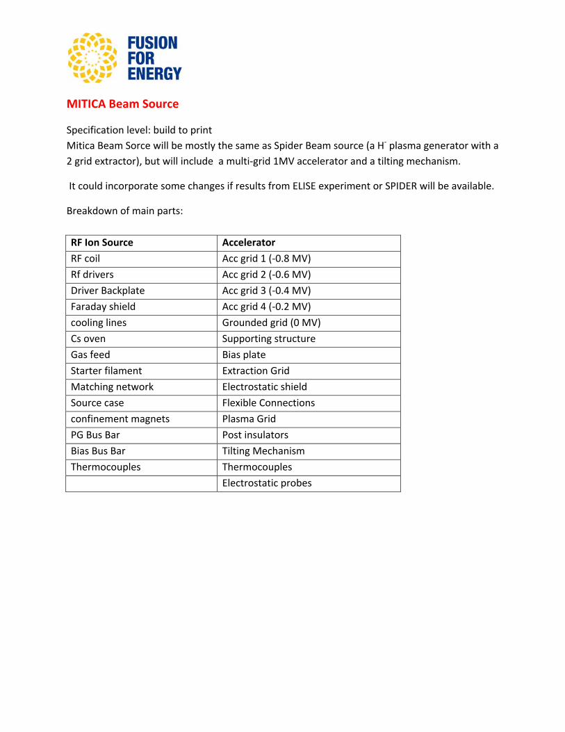
MITICA Beam Source
Specification level: build to print Mitica Beam Sorce will be mostly the same as Spider Beam source (a H‐ plasma generator with a 2 grid extractor), but will include a multi‐grid 1MV accelerator and a tilting mechanism.
It could incorporate some changes if results from ELISE experiment or SPIDER will be available.
Breakdown of main parts:
RF Ion Source Accelerator
RF coil Acc grid 1 (‐0.8 MV)
Rf drivers Acc grid 2 (‐0.6 MV)
Driver Backplate Acc grid 3 (‐0.4 MV)
Faraday shield Acc grid 4 (‐0.2 MV)
cooling lines Grounded grid (0 MV)
Cs oven Supporting structure
Gas feed Bias plate
Starter filament Extraction Grid
Matching network Electrostatic shield
Source case Flexible Connections
confinement magnets Plasma Grid
PG Bus Bar Post insulators
Bias Bus Bar Tilting Mechanism
Thermocouples Thermocouples
Electrostatic probes
The contract will cover manufacturing and assembly of the parts. It is a high vacuum compatible component, with The design work is not included in the contract. The specification at a build to print level will be provided by IO. The design work is being carried out by RFX and associated CCFE under a grant. Critical technologies required are:
‐ Electro‐deposition process for the fabrication of the grid segments and ion source inner components.
‐ Mo/W coating of ion source plasma facing inner surfaces.
The component will be factory tested in a vacuum environment before acceptance.
Tentative Planning: Second semester 2013
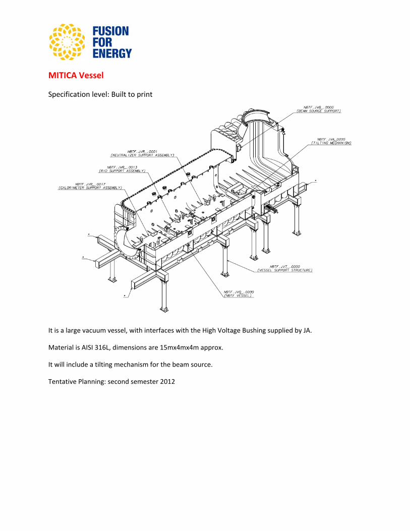
MITICA Vessel
Specification level: Built to print
It is a large vacuum vessel, with interfaces with the High Voltage Bushing supplied by JA.
Material is AISI 316L, dimensions are 15mx4mx4m approx.
It will include a tilting mechanism for the beam source.
Tentative Planning: second semester 2012
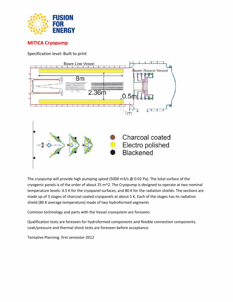
MITICA Cryopump
Specification level: Built to print
The cryopump will provide high pumping speed (5000 m3/s @ 0.02 Pa). The total surface of the cryogenic panels is of the order of about 25 m^2. The Cryopump is designed to operate at two nominal temperature levels: 4.5 K for the cryopanel surfaces, and 80 K for the radiation shields. The sections are made up of 3 stages of charcoal coated cryopanels at about 5 K. Each of the stages has its radiation shield (80 K average temperature) made of two hydroformed segments
Common technology and parts with the Vessel cryosystem are foreseen.
Qualification tests are foreseen for hydroformed components and flexible connection components. Leak/pressure and thermal shock tests are foreseen before acceptance.
Tentative Planning: first semester 2012
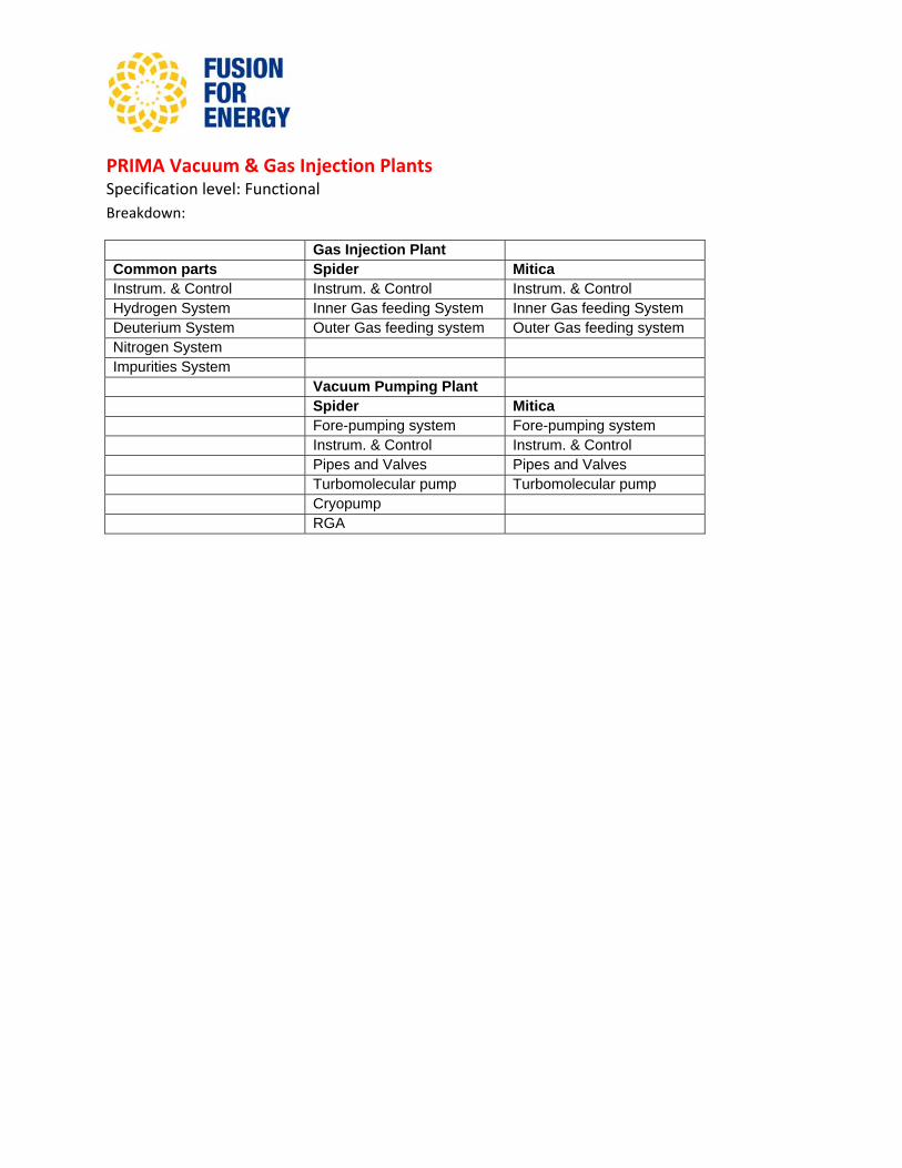
PRIMA Vacuum & Gas Injection Plants Specification level: Functional Breakdown:
Gas Injection Plant Common parts Spider Mitica Instrum. & Control Instrum. & Control Instrum. & Control Hydrogen System Inner Gas feeding System Inner Gas feeding System Deuterium System Outer Gas feeding system Outer Gas feeding system Nitrogen System Impurities System Vacuum Pumping Plant Spider Mitica Fore-pumping system Fore-pumping system Instrum. & Control Instrum. & Control Pipes and Valves Pipes and Valves Turbomolecular pump Turbomolecular pump Cryopump RGA
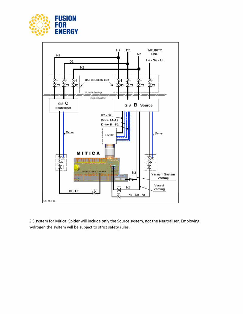
GIS system for Mitica. Spider will include only the Source system, not the Neutraliser. Employing hydrogen the system will be subject to strict safety rules.
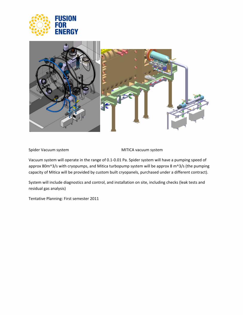
Spider Vacuum system MITICA vacuum system
Vacuum system will operate in the range of 0.1‐0.01 Pa. Spider system will have a pumping speed of approx 80m^3/s with cryopumps, and Mitica turbopump system will be approx 8 m^3/s (the pumping capacity of Mitica will be provided by custom built cryopanels, purchased under a different contract).
System will include diagnostics and control, and installation on site, including checks (leak tests and residual gas analysis)
Tentative Planning: First semester 2011
MITICA RMFCs Specification level: Build to print
Breakdown
Res Magnetic Field Coils 1 up P6 str. assembly Res Magnetic Field Coils 2 low P6 str. assembly. Res Magnetic Field Coils 3 up P4-P5 str. assembly. Res Magnetic Field Coils 4 low P4-P5 str. assembly. Res Magnetic Field Coils 5 up P1-P2-P3 str. assembly. Res Magnetic Field Coils 6 Low P1-P2-P3 str. assembly.
It includes coils for magnetic field control. Power supplies are out of the scope.