86
Neutrino-224 Indoor 2x125mW FDD/TDD eNodeB Installation Guide December 2018 Version 1.7

Neutrino-224 Indoor 2x125mW FDD/TDD eNodeB
Installation Guide
December 2018
Version 1.7

2
About This Document This document is intended for anyone who will be installing the Baicells Neutrino-224 Indoor 2x125mW eNodeB (eNB). The 3GPP standards-based Neutrino eNB provides broadband wireless access to Long-Term Evolution (LTE) Frequency Division Duplexing (FDD) and Time Division Duplexing (TDD) backhaul networks. The information includes planning considerations, installation procedures, and configuration guidance.
The eNB GUI may vary based on software version and based on FDD or TDD operation. This document includes both FDD and TDD configuration fields based on:
• FDD software version BaiBS_QATA_1.3.3
• TDD software version BaiBS_QATA_2.2.2
Copyright Notice Baicells Technologies, Inc., copyrights the information in this document. No part of this document may be reproduced in any form or means without the prior written consent of Baicells Technologies, Inc.
Disclaimer The information in this document is subject to change at any time without notice. For more information, please consult with a Baicells technical engineer or the support team. Refer to the “Contact Us” section below.
Disposal of Electronic and Electrical Waste Pursuant to the WEEE EU Directive, electronic and electrical waste must not be disposed of with unsorted waste. Please contact your local recycling authority for disposal of this product.
3
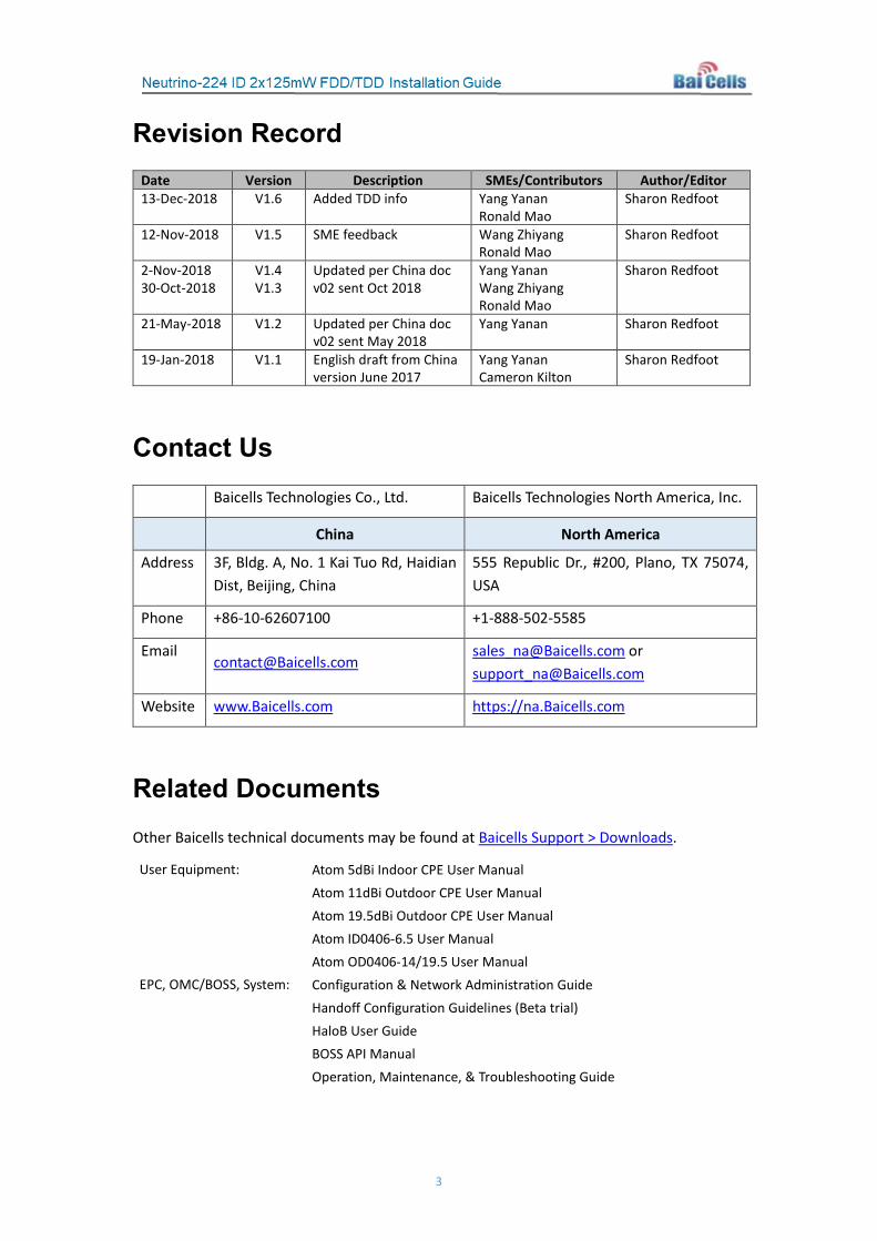
Revision Record Date Version Description SMEs/Contributors Author/Editor 13-Dec-2018 V1.6 Added TDD info Yang Yanan
Ronald Mao Sharon Redfoot
12-Nov-2018 V1.5 SME feedback Wang Zhiyang Ronald Mao
Sharon Redfoot
2-Nov-2018 30-Oct-2018
V1.4 V1.3
Updated per China doc v02 sent Oct 2018
Yang Yanan Wang Zhiyang Ronald Mao
Sharon Redfoot
21-May-2018 V1.2 Updated per China doc v02 sent May 2018
Yang Yanan Sharon Redfoot
19-Jan-2018 V1.1 English draft from China version June 2017
Yang Yanan Cameron Kilton
Sharon Redfoot
Contact Us Baicells Technologies Co., Ltd. Baicells Technologies North America, Inc.
China North America
Address 3F, Bldg. A, No. 1 Kai Tuo Rd, Haidian Dist, Beijing, China
555 Republic Dr., #200, Plano, TX 75074, USA
Phone +86-10-62607100 +1-888-502-5585
Email [email protected]
[email protected] or [email protected]
Website www.Baicells.com https://na.Baicells.com
Related Documents Other Baicells technical documents may be found at Baicells Support > Downloads.
User Equipment: Atom 5dBi Indoor CPE User Manual Atom 11dBi Outdoor CPE User Manual Atom 19.5dBi Outdoor CPE User Manual Atom ID0406-6.5 User Manual Atom OD0406-14/19.5 User Manual EPC, OMC/BOSS, System: Configuration & Network Administration Guide Handoff Configuration Guidelines (Beta trial) HaloB User Guide BOSS API Manual Operation, Maintenance, & Troubleshooting Guide
4
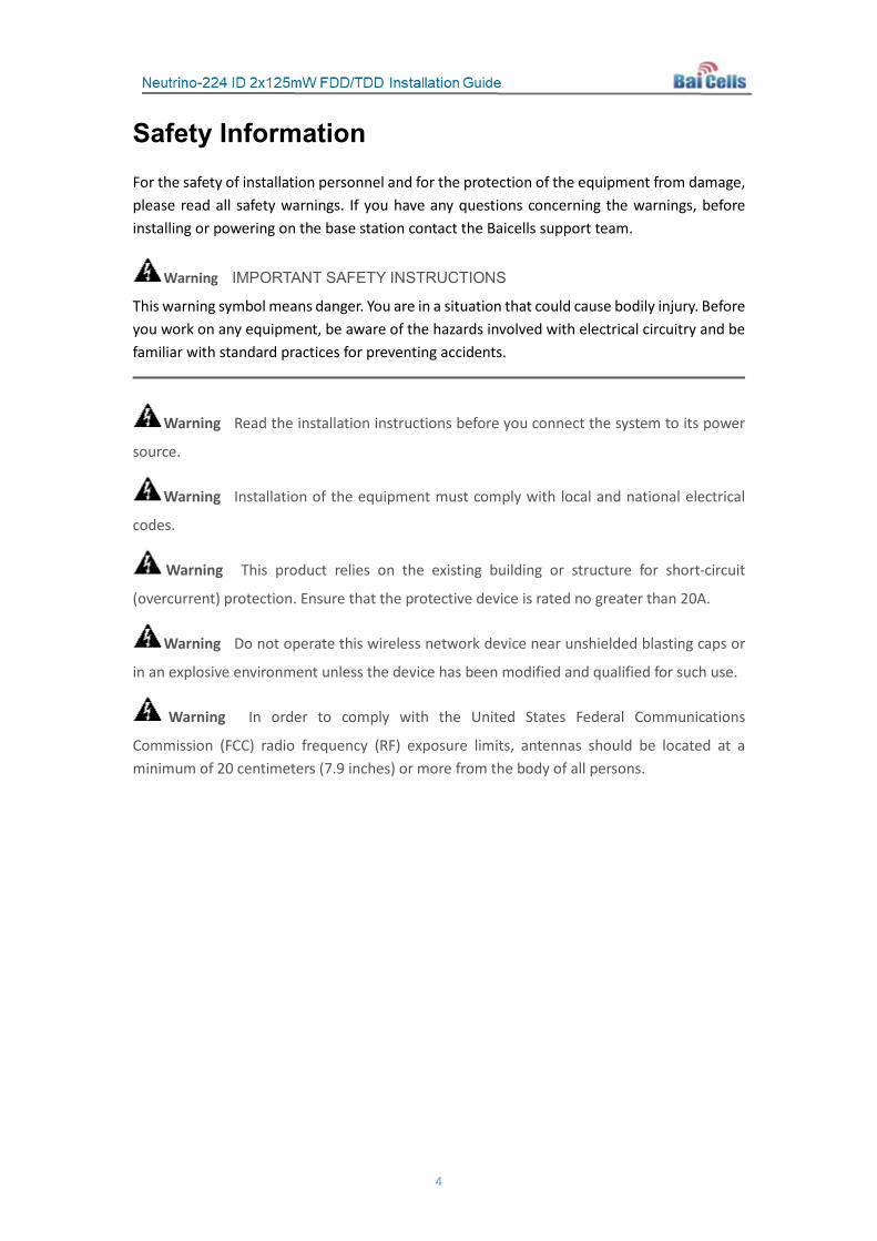
Safety Information For the safety of installation personnel and for the protection of the equipment from damage, please read all safety warnings. If you have any questions concerning the warnings, before installing or powering on the base station contact the Baicells support team.
Warning IMPORTANT SAFETY INSTRUCTIONS
This warning symbol means danger. You are in a situation that could cause bodily injury. Before you work on any equipment, be aware of the hazards involved with electrical circuitry and be familiar with standard practices for preventing accidents.
Warning Read the installation instructions before you connect the system to its power
source.
Warning Installation of the equipment must comply with local and national electrical
codes.
Warning This product relies on the existing building or structure for short-circuit
(overcurrent) protection. Ensure that the protective device is rated no greater than 20A.
Warning Do not operate this wireless network device near unshielded blasting caps or
in an explosive environment unless the device has been modified and qualified for such use.
Warning In order to comply with the United States Federal Communications
Commission (FCC) radio frequency (RF) exposure limits, antennas should be located at a minimum of 20 centimeters (7.9 inches) or more from the body of all persons.
5
Table of Contents 1 Overview ...................................................................................................................... 9
1.1 Introduction ................................................................................................................. 9 1.2 Features ..................................................................................................................... 10
2 Planning ...................................................................................................................... 11 2.1 Network & Site Planning ............................................................................................ 11 2.2 Mounting Options...................................................................................................... 11 2.3 Client Computer Requirements ................................................................................. 11 2.4 Form Factor ................................................................................................................ 12
3 Verify Basic Operation ................................................................................................. 14 3.1 Connect Power Cable................................................................................................. 14 3.2 Power On ................................................................................................................... 14
4 Mounting the Unit ....................................................................................................... 15 4.1 Preparation ................................................................................................................ 15 4.2 Ceiling Installation ..................................................................................................... 15 4.3 Wall Installation ......................................................................................................... 17 4.4 Connect Cables .......................................................................................................... 17 4.5 Power on .................................................................................................................... 17 4.6 Check eNB Status in Software ................................................................................... 17
4.6.1 Computer Requirements ................................................................................. 17 4.6.2 Prepare the Client Computer ........................................................................... 18 4.6.3 eNB GUI ........................................................................................................... 19
5 Configuration .............................................................................................................. 21 5.1 Quick Setting .............................................................................................................. 21 5.2 Network ..................................................................................................................... 23
5.2.1 WAN ................................................................................................................. 23 5.2.2 LAN .................................................................................................................. 25 5.2.3 Route ............................................................................................................... 27 5.2.4 Host .................................................................................................................. 28 5.2.5 IPSec ................................................................................................................ 29 5.2.6 BACKHAUL ....................................................................................................... 35
5.3 BTS Setting ................................................................................................................. 36 5.3.1 Security Setting ................................................................................................ 36 5.3.2 Management Server ........................................................................................ 36 5.3.3 Sync Setting ..................................................................................................... 37 5.3.4 License Management ...................................................................................... 39
5.4 System ....................................................................................................................... 39 5.4.1 NTP .................................................................................................................. 39 5.4.2 Upgrade ........................................................................................................... 40 5.4.3 Backup ............................................................................................................. 42 5.4.4 Password .......................................................................................................... 43 5.4.5 CertStore .......................................................................................................... 44

6
5.5 LTE Setting .................................................................................................................. 44 5.5.1 Neighbor Cells & Mobility ................................................................................ 45 5.5.2 Other LTE Settings ............................................................................................ 71
5.6 Reboot ....................................................................................................................... 79 Appendix A: Technical Specifications .............................................................................. 80
Hardware Specifications .................................................................................................. 80 Software Specifications ................................................................................................... 81 Environmental Specifications .......................................................................................... 82 Global Part Numbers ....................................................................................................... 82
Appendix B: FAQs ........................................................................................................... 83 Appendix C: Abbreviations & Acronyms .......................................................................... 84
List of Figures Figure 1-1: Neutrino-224 eNB ................................................................................................... 9 Figure 1-2: Baicells Broadband Wireless Access Solution with Neutrino-224 eNB ................. 10 Figure 2-1: Form Factor ........................................................................................................... 12 Figure 2-2: LEDs & Interfaces ................................................................................................... 12 Figure 3-1: LEDs & Interfaces ................................................................................................... 14 Figure 4-1: Attach Bracket ....................................................................................................... 15 Figure 4-2: Mark Drilling Holes ................................................................................................ 16 Figure 4-3: Fix Bracket to Ceiling Panel.................................................................................... 16 Figure 4-4: Attach Unit to Bracket ........................................................................................... 16 Figure 4-5: Internet Protocol Version (TCP/IPV4) .................................................................... 18 Figure 4-6: eNB GUI Login ....................................................................................................... 19 Figure 4-7: FDD eNB GUI Home Page ...................................................................................... 20 Figure 4-8: TDD eNB GUI Home Page ...................................................................................... 20 Figure 5-1: FDD Quick Setting .................................................................................................. 21 Figure 5-2: TDD Quick Setting .................................................................................................. 22 Figure 5-3: WAN....................................................................................................................... 24 Figure 5-4: Multi link mode configuration ............................................................................... 25 Figure 5-5: LAN ........................................................................................................................ 26 Figure 5-6: LAN Internet Config ............................................................................................... 26 Figure 5-7: Route ..................................................................................................................... 27 Figure 5-8: Host ....................................................................................................................... 29 Figure 5-9: IPSec ...................................................................................................................... 30 Figure 5-10: IPSec Tunnel – Basic Setting ................................................................................ 31 Figure 5-11: IPSec Tunnel – Advance Setting ........................................................................... 33 Figure 5-12: Backhaul .............................................................................................................. 35 Figure 5-13: Security Setting.................................................................................................... 36 Figure 5-14: Management Server ............................................................................................ 37 Figure 5-15: FDD Sync Setting .................................................................................................. 37 Figure 5-16: TDD Sync Setting ................................................................................................. 38
7
Figure 5-17: License Management .......................................................................................... 39 Figure 5-18: NTP ...................................................................................................................... 40 Figure 5-19: Upgrade ............................................................................................................... 41 Figure 5-20: Backup ................................................................................................................. 42 Figure 5-21: CertStore ............................................................................................................. 44 Figure 5-22: LTE Setting ........................................................................................................... 45 Figure 5-23: LTE Freq/Cell ........................................................................................................ 46 Figure 5-24: LTE Neigh Freq Settings (1 of 2) ........................................................................... 47 Figure 5-25: LTE Neigh Freq Settings (2 of 2) ........................................................................... 47 Figure 5-26: LTE Neigh Cell Settings......................................................................................... 50 Figure 5-27: 3G Freq/Cell ......................................................................................................... 52 Figure 5-28: 3G Neigh Cell Settings ......................................................................................... 53 Figure 5-29: GSM Freq/Cell ..................................................................................................... 55 Figure 5-30: Handoff ................................................................................................................ 57 Figure 5-31: Mobility Parameter ............................................................................................. 58 Figure 5-32: A3 Event Threshold ............................................................................................. 62 Figure 5-33: A4 Event Threshold ............................................................................................. 63 Figure 5-34: A5 Event Threshold ............................................................................................. 63 Figure 5-35: Measurement Control Parameter ....................................................................... 63 Figure 5-36: B2 Event Threshold .............................................................................................. 63 Figure 5-37: Cell Selection Parameter ..................................................................................... 63 Figure 5-38: Cell ReSelection Parameter ................................................................................. 64 Figure 5-39: Additional Measurement Parameter .................................................................. 64 Figure 5-40: Advanced ............................................................................................................. 65 Figure 5-41: SON Functional .................................................................................................... 68 Figure 5-42: Scheduling Algorithm .......................................................................................... 69 Figure 5-43: MOCN Parameters (1 of 2) .................................................................................. 72 Figure 5-44: MOCN Parameters (2 of 2) .................................................................................. 72 Figure 5-45: RRC Parameter (1 of 2) ........................................................................................ 73 Figure 5-46: RRC Parameter (2 of 2) ........................................................................................ 73 Figure 5-47: Capacity Parameter ............................................................................................. 74 Figure 5-48: Random Access & Capacity Parameters .............................................................. 75 Figure 5-49: Log Config ............................................................................................................ 76 Figure 5-50: LTE log level & phyTraceSubsystemConfig ........................................................... 78 Figure 5-51: phyTraceConfig .................................................................................................... 78 Figure 5-52: phyTraceNetworkCaptureConfig ......................................................................... 79 Figure 5-53: boardConf ............................................................................................................ 79

8
List of Tables Table 2-1: Client Computer Requirements .............................................................................. 11 Table 2-2: LEDs & Interfaces .................................................................................................... 12 Table 2-3: LED Color States ...................................................................................................... 13 Table 4-1: Computer Requirements ........................................................................................ 17 Table 5-1: Quick Setting ........................................................................................................... 22 Table 5-2: WAN Interface ......................................................................................................... 24 Table 5-3: Multi link mode configuration ................................................................................ 25 Table 5-4: LAN Internet ............................................................................................................ 26 Table 5-5: Static Route ............................................................................................................. 27 Table 5-6: Host ......................................................................................................................... 29 Table 5-7: IPSec Tunnel – Basic Setting .................................................................................... 31 Table 5-8: IPSec Tunnel – Advance Setting .............................................................................. 33 Table 5-9: BACKHAUL ............................................................................................................... 35 Table 5-10: Security Setting ..................................................................................................... 36 Table 5-11: Sync Setting ........................................................................................................... 38 Table 5-12: NTP ........................................................................................................................ 40 Table 5-13: Neighbor LTE eNB Frequencies ............................................................................. 48 Table 5-14: Neigh Cell List ........................................................................................................ 50 Table 5-15: Neigh Freq List ...................................................................................................... 52 Table 5-16: Neigh Cell List ........................................................................................................ 54 Table 5-17: Neigh Freq List ...................................................................................................... 55 Table 5-18: Neigh Cell List ........................................................................................................ 56 Table 5-19: Mobility Parameter ............................................................................................... 58 Table 5-20: Power Control Parameters .................................................................................... 66 Table 5-21: eNodeB Settings .................................................................................................... 67 Table 5-22: GAP Setting ........................................................................................................... 67 Table 5-23: SON Setting ........................................................................................................... 68 Table 5-24: Scheduling Algorithm ............................................................................................ 69 Table 5-25: eNodeB Range ...................................................................................................... 70 Table 5-26: Cfsb Select ............................................................................................................. 71 Table 5-27: RAT Handover Priority ........................................................................................... 71 Table 5-28: MOCN Parameters ................................................................................................ 72 Table 5-29: RRC Parameter ...................................................................................................... 73 Table 5-30: Capacity Parameter ............................................................................................... 75 Table 5-31: Log Config ............................................................................................................. 77
9
1 Overview
1.1 Introduction
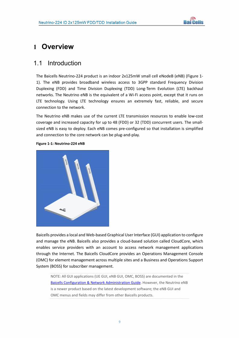
The Baicells Neutrino-224 product is an indoor 2x125mW small cell eNodeB (eNB) (Figure 1-1). The eNB provides broadband wireless access to 3GPP standard Frequency Division Duplexing (FDD) and Time Division Duplexing (TDD) Long-Term Evolution (LTE) backhaul networks. The Neutrino eNB is the equivalent of a Wi-Fi access point, except that it runs on LTE technology. Using LTE technology ensures an extremely fast, reliable, and secure connection to the network.
The Neutrino eNB makes use of the current LTE transmission resources to enable low-cost coverage and increased capacity for up to 48 (FDD) or 32 (TDD) concurrent users. The small-sized eNB is easy to deploy. Each eNB comes pre-configured so that installation is simplified and connection to the core network can be plug-and-play.
Figure 1-1: Neutrino-224 eNB
Baicells provides a local and Web-based Graphical User Interface (GUI) application to configure and manage the eNB. Baicells also provides a cloud-based solution called CloudCore, which enables service providers with an account to access network management applications through the Internet. The Baicells CloudCore provides an Operations Management Console (OMC) for element management across multiple sites and a Business and Operations Support System (BOSS) for subscriber management.
NOTE: All GUI applications (UE GUI, eNB GUI, OMC, BOSS) are documented in the Baicells Configuration & Network Administration Guide. However, the Neutrino eNB is a newer product based on the latest development software; the eNB GUI and OMC menus and fields may differ from other Baicells products.

10
The cloud-based Evolved Packet Core (EPC) functions may be managed by Baicells to provide high-speed packet processing and high-quality mobile broadband services end-to-end.
The system architecture, including Neutrino-224 eNBs, is illustrated in Figure 1-2.
Figure 1-2: Baicells Broadband Wireless Access Solution with Neutrino-224 eNB
1.2 Features
The Neutrino-224 eNB is based on LTE Standard 3GPP Release 9. Following is a list of the key features of this product:
• Standard LTE network modes:
- FDD bands 1, 2, 3, 4, 5, 7, and customized
- TDD bands 40, 41, 42, 43, 48, and customized
• Peak rate with 20 MHz spectrum:
- FDD: 150 Mbps DL, 50 Mbps UL
- TDD: 110 Mbps DL, 20 Mbps UL
• Maximum 48 (FDD) and 32 (TDD) concurrent users per cell
• Supports 5/10/15/20 MHz operation bandwidth
• Plug-and-play with SON capabilities
• Built-in DHCP server, DNS client, and NAT functionality
• Integrated high-gain antenna
• Local and Web GUI, network management through BaiOMC
11
2 Planning
2.1 Network & Site Planning
When installing multiple Neutrino eNodeBs (eNBs) in the same general location, for example to cover an entire floor of a building, you will need to perform network and site planning to ensure that all target areas are properly covered for wireless service. Radio Frequency (RF) performance can be diminished by numerous factors, including interference from other eNBs and other radiating devices, and the existence of walls or other obstructions.
You need to consider the density of users and the required capacity to meet their needs. The selected frequency, power, and other settings also affect RF performance. For these reasons, you should perform a site survey and plan the distance between eNBs. A site survey may be ad hoc, or you may wish to use a third-party site survey and RF planning application, or you can hire professionals to complete the planning.
Other types of network planning involve IP addressing; the selection of unique network and cell site identifiers that are used when configuring LTE networks; and for each installation site, the availability of a power source as well as proximity to the local gateway equipment.
2.2 Mounting Options
The Baicells Neutrino-224 eNB was designed for easy deployment. The unit can sit on a desktop or be installed on a ceiling or a wall.
Before placing or installing the eNB at its final location, Baicells recommends that you connect power to the unit in order to verify the status of the PWR LED indicator. How to do this is explained in section 3.
2.3 Client Computer Requirements
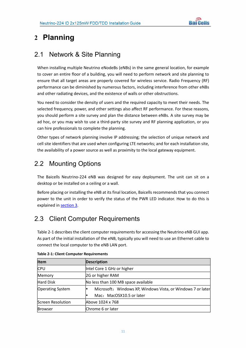
Table 2-1 describes the client computer requirements for accessing the Neutrino eNB GUI app. As part of the initial installation of the eNB, typically you will need to use an Ethernet cable to connect the local computer to the eNB LAN port.
Table 2-1: Client Computer Requirements
Item Description CPU Intel Core 1 GHz or higher Memory 2G or higher RAM Hard Disk No less than 100 MB space available Operating System Microsoft:Windows XP, Windows Vista, or Windows 7 or later
Mac:MacOSX10.5 or later Screen Resolution Above 1024 x 768 Browser Chrome 6 or later

12
2.4 Form Factor
The Neutrino eNB has a sleek form factor (Figure 2-1):
• Height with antennas – 7 inches / 175 mm
• Height of base – 1 inch / 30 mm
• Width – 5 inches / 130 mm
The unit only weighs approximately one pound (500 g).
Figure 2-1: Form Factor
Figure 2-2 shows the LED indicators and interfaces on the back of the unit. The LEDs and interfaces are described in Tables 2-2 and 2-3.
Figure 2-2: LEDs & Interfaces
Table 2-2: LEDs & Interfaces
LED/Interface Description RST Reset button GPS Optional*: External Global Positioning System (GPS) antenna
connector, SMA male connector type LAN Gigabit Ethernet Local Area Network (LAN) interface WAN Gigabit Ethernet Wide Area Network (WAN) interface for
backhaul PWR Power interface: 220V AC to 12V DC power adaptor

13
*NOTE: Some users may want to add a GPS antenna to better ensure accurate physical location information used by the eNB during transmissions. Follow the GPS vendor’s installation requirements to install a GPS antenna with the Neutrino eNB.
Table 2-3: LED Color States
Color Status Description
White
Steady on The device is powered on.
Slow flash The device is ready to transmit/receive data.
Fast flash The device is transmitting data.
Red
Steady on Alarm indicating strong interference may be affecting network performance
Slow flash Other types of alarms are occurring
Fast flash S1 alarm – the device cannot reach the backhaul network (Internet)
Please refer to Appendix A for all of the Neutrino technical specifications.

14
3 Verify Basic Operation Before installing the Neutrino eNodeB (eNB), especially if placing it on a ceiling or wall, you should check that:
• You have all of the parts on the packing list;
• You have the standard tools at hand to perform the installation; and
• The eNB unit will power on successfully.
This section walks you through the steps of verifying that the Neutrino eNB is operational and ready for installation.
3.1 Connect Power Cable
Refer to Figure 3-1 to connect power to the eNB. Connect the power adaptor to the power (PWR) port on the unit, and plug the other end into an AC power outlet.
Figure 3-1: LEDs & Interfaces
3.2 Power On
Power on the Neutrino eNB. The PWR LED should light up with a steady white light, as described in Table 2-3 above. The other LEDs will not activate or may display alarm status pre-installation. You will be checking those LEDs later in the process once the installation and basic configuration steps are completed.
If the eNB does not power on or the PWR LED is not lit up, please verify that the connection setup is correct. Otherwise, contact your supplier immediately for a replacement.

15
4 Mounting the Unit This section covers how to install the Neutrino eNodeB (eNB) on a ceiling or wall. If you completed the steps in section 3 Verify Basic Operation, as recommended, uninstall the power connections from the eNB before installing the unit on a ceiling or wall.
4.1 Preparation
If you plan to install the Neutrino eNodeB (eNB) on a ceiling or wall, you will need a marker pencil and a percussion drill to install the bracket that holds the eNB. Go to section 4.2 for a ceiling installation, or to section 4.3 for a wall installation.
Some operators may want to add a GPS antenna to ensure accurate physical location information used by the eNB during transmissions. To connect the antenna you will use the GPS interface on the eNB. Follow the GPS vendor’s installation requirements to install a GPS antenna with the Baicells Neutrino-224 eNB.
4.2 Ceiling Installation
Review the following guidelines for installing the Neutrino-224 eNB unit on a ceiling. The installation steps follow.
The thickness of the ceiling should be no less than ½ inch/18 mm, and should be able to bear more than 11 lbs/5 kg weight.
If the ceiling is made of weak materials, such as a gypsum, this installation method is not recommended. Because of the environment restrictions, to continue with a ceiling mount in this situation add one layer of stronger panel under the screws to make sure the device is secure.
1. Attach the bracket under the Neutrino eNB unit using the M3*10 cross round head screws (Figure 4-1).
Figure 4-1: Attach Bracket
2. Remove the selected ceiling panel.

16
3. Place the bracket on the center of the ceiling panel, and mark the drilling hole locations with a marker pen (Figure 4-2).
Figure 4-2: Mark Drilling Holes
4. Drill the 3 holes that you marked, deep enough to receive the expansion bolts.
5. Use the expansion bolts to fix the installation bracket on the ceiling panel, and tighten the screws (Figure 4-3).
Figure 4-3: Fix Bracket to Ceiling Panel
6. Slide the Neutrino unit onto the bracket according to the arrow indicator (Figure 4-4). Proceed to section 4.4.
Figure 4-4: Attach Unit to Bracket

17
4.3 Wall Installation
The steps for installing a Neutrino eNB on a wall are the same as when installing it on a ceiling, as covered in section 4.2 Ceiling Installation, with the exception that you will need to adjust the direction of the arrow on the bracket according to the wall placement. Be sure the 3 holes for the bolts are in the correct position.
Proceed to section 4.4, next.
4.4 Connect Cables
Connect the power adaptor to the unit and outlet, as explained in section 3 Verify Basic Operation. Do not power on the unit yet.
Connect an Ethernet cable to the WAN port on the unit; the other end connects to the backhaul device.
4.5 Power on
Power on the Neutrino eNB. It may take a minute or two for the LEDs to provide status information. Refer to Table 2-3 LED Status to ensure the PWR LED is showing a steady white light. The other LED will be more accurate after you complete the basic configuration, which is discussed in section 5 Configuration.
4.6 Check eNB Status in Software
The Baicells eNBs are designed to be plug-and-play and, therefore, arrive with many parameters pre-configured using default values. You will need to connect a computer to the LAN port using an Ethernet cable to ensure the eNB status is reported as active before you continue with the installation.
4.6.1 Computer Requirements
The client computer you use to interface with the LAN port on the eNB must meet the following minimum requirements shown in Table 4-1.
Table 4-1: Computer Requirements
Item Description CPU Intel Core 1GHz or higher Memory > 2G RAM Hard Disk > 100 MB space available Operating system Microsoft: Windows XP, Windows Vista, or Windows7
Mac: MacOSX10.5 or later Screen resolution > 1024 x 768 Browser Chrome 6 or higher
18
4.6.2 Prepare the Client Computer
4.6.2.1 Connect Ethernet Cable
Connect one end of an Ethernet cable to the LAN port on the eNB and the other end to your computer. Initially, you will use this local connection to access the eNB GUI application to verify the eNB’s status and to configure a few basic settings. Make sure the client computer and the LAN interface are configured and attached to the same local area network.
4.6.2.2 Client Setup
To establish the connection between the client computer and the eNB, please ensure the IP addressing is set up correctly. Following is an example for a Windows 7 PC.
1. Select Start > Control Panel, and in the pop-up window click on Network and Internet.
2. Click on View network status and tasks, and then click on Local Connectivity.
3. In the window labeled Status of Local Connectivity, click on Properties. This will open the Properties of Local Connectivity window.
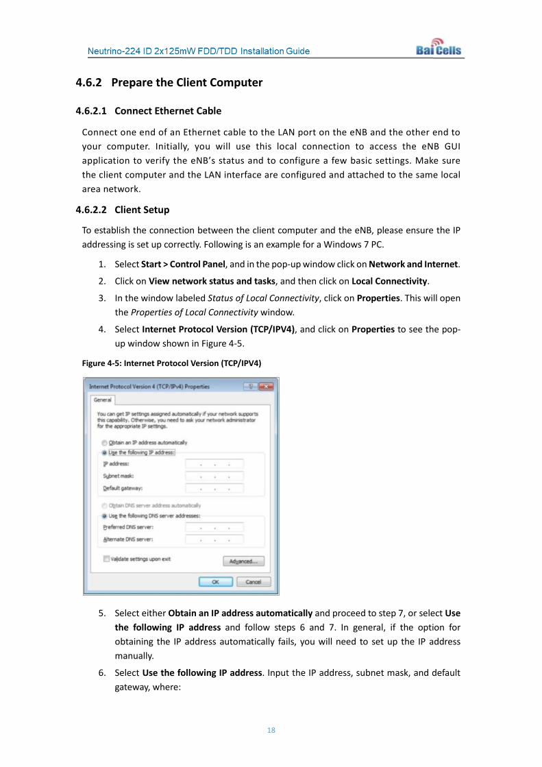
4. Select Internet Protocol Version (TCP/IPV4), and click on Properties to see the pop-up window shown in Figure 4-5.
Figure 4-5: Internet Protocol Version (TCP/IPV4)
5. Select either Obtain an IP address automatically and proceed to step 7, or select Use the following IP address and follow steps 6 and 7. In general, if the option for obtaining the IP address automatically fails, you will need to set up the IP address manually.
6. Select Use the following IP address. Input the IP address, subnet mask, and default gateway, where:
19
a. IP address is 192.168.150.xxx (where xxx is a number from 100 to 254).
b. Subnet mask is 255.255.255.0.
c. Default gateway is 192.168.150.1.
7. In the command window, execute a ping to 192.168.150.1, and check whether the connection between the client computer and the eNB is working.
4.6.3 eNB GUI
NOTE: The eNB GUI menus vary according to software version and based on FDD or TDD operation. Both FDD and TDD GUIs are covered in this document.
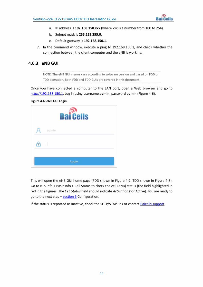
Once you have connected a computer to the LAN port, open a Web browser and go to http://192.168.150.1. Log in using username admin, password admin (Figure 4-6).
Figure 4-6: eNB GUI Login
This will open the eNB GUI home page (FDD shown in Figure 4-7, TDD shown in Figure 4-8). Go to BTS Info > Basic Info > Cell Status to check the cell (eNB) status (the field highlighted in red in the figures. The Cell Status field should indicate Activation (for Active). You are ready to go to the next step – section 5 Configuration.
If the status is reported as inactive, check the SCTP/S1AP link or contact Baicells support.

20
Figure 4-7: FDD eNB GUI Home Page
Figure 4-8: TDD eNB GUI Home Page
21
5 Configuration NOTE: The eNB GUI menus vary according to software version and based on FDD or TDD operation. Both FDD and TDD GUIs are covered in this document.
The configuration procedures covered in this section are illustrated using the eNodeB (eNB) GUI. The information assumes you have read and completed the previous steps in section 4.
For more information on Baicells network configuration and subscriber management, please refer to the Baicells Configuration & Network Administration Guide.
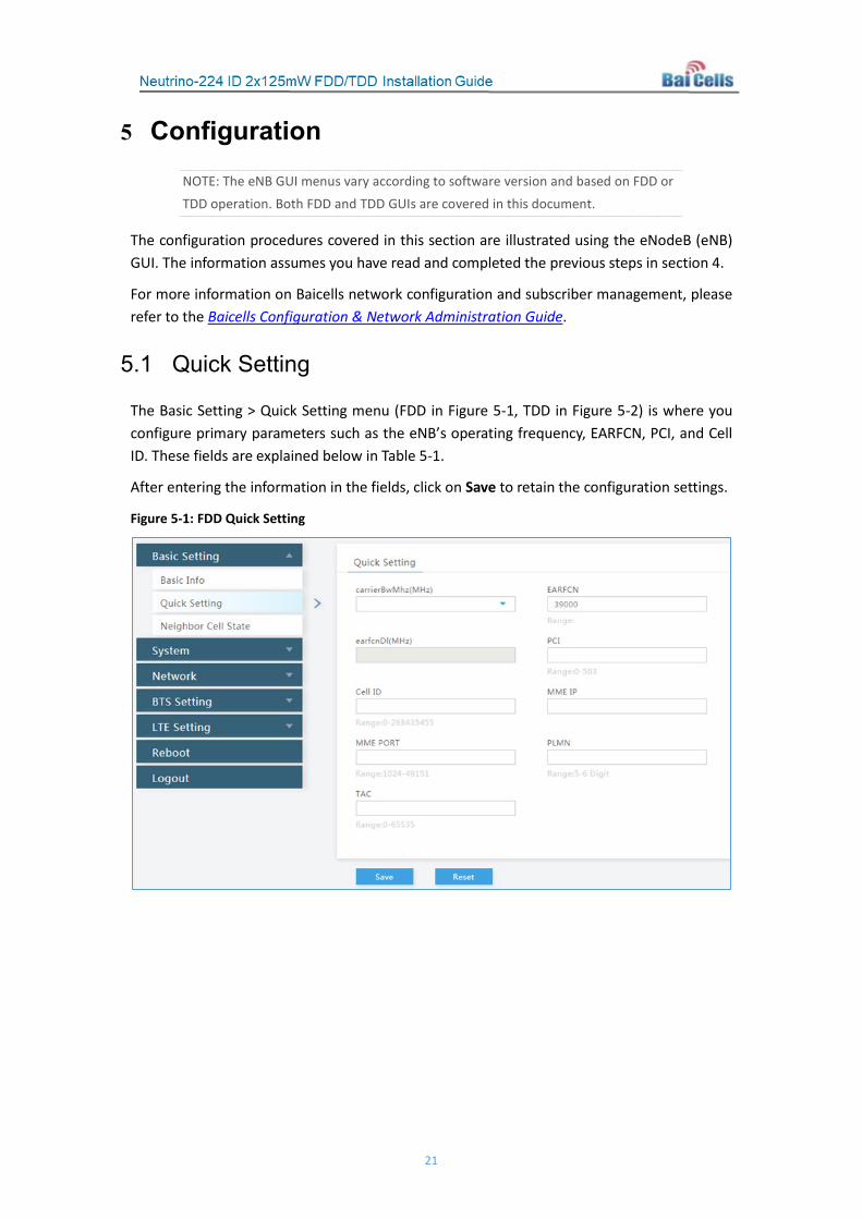
5.1 Quick Setting
The Basic Setting > Quick Setting menu (FDD in Figure 5-1, TDD in Figure 5-2) is where you configure primary parameters such as the eNB’s operating frequency, EARFCN, PCI, and Cell ID. These fields are explained below in Table 5-1.
After entering the information in the fields, click on Save to retain the configuration settings.
Figure 5-1: FDD Quick Setting

22
Figure 5-2: TDD Quick Setting
Table 5-1: Quick Setting
Parameter Name Description carrierBwMhz The bandwidth used by the eNB, as pre-planned by the operator.
Options are 5 MHz, 10 MHz, 15 MHz, or 20 MHz. EARFCN The absolute radio frequency channel number, assigned by the
operator. Range: 38750 - 39250 earfcnDI (MHz) The eNB’s operating frequency, assigned by the operator. The
range depends on the eNB model. PCI Physical Cell Identification (PCI), assigned by the operator.
Range: 0 to 503. PCI is Layer 1 identity, an essential configuration parameter of a radio cell that uniquely identifies each cell site in the wireless network. PCI planning is crucial for quality of service (QoS).
Cell ID The logical cell identification (ID) randomly assigned to this eNB. Range: 0 to 268,435,455.
MME PORT The MME port of the IP address PLMN The numerical identifier for the operator’s Public Land Mobile
Network (PLMN) for this cell. Must be a 5- or 6-digit number. Assigned by the operator.
TAC Tracking Area Code (TAC) where the eNB is located. The TAC is used to determine the range of the paging information. The operator can use a number between 0 to 65,535. The default is 1.
subFrameAssignment Downlink (DL) and uplink (UL) subframe configuration, either 1 or 2, where:

23
Parameter Name Description 1 = DL:UL is 2:2 transmission ratio 2 = DL:UL is 3:1 transmission ratio (default) Refer to the BaiTip on this setting:
https://community.na.baicells.com/t/baitip-of-the-day-december-14th-2016-subframes-and-special-subframes/163
specialSubframePatterns Either 5 or 7. This is a standard LTE setting that pertains to synchronization of downlink and uplink timing. The guard period between switching from DL to UL or UL to DL determines the maximum supportable cell size. The guard period has to be large enough to cover the propagation delay of DL interferers. The default setting is 7.
Refer to the BaiTip on this setting: https://community.na.baicells.com/t/baitip-of-the-day-december-14th-2016-subframes-and-special-
subframes/163 s1ConnectionMode Number of S1AP signaling end points with which the eNB
attempts to establish a connection. If the signaling end points in the s1SigLinkServerList contain at least one MME, the s1ConnectionMode should be set to One. Otherwise, the s1ConnectionMode can be set to one or all. Options:
• One • All
MME IP The Internet Protocol (IP) address of the Mobility Management Entity (MME). The MME is responsible for initiating paging and authentication of mobile devices. There may be more than one MME in the network.
5.2 Network
5.2.1 WAN
The WAN interface is a communications interface to external devices in the network, such as the Network Management System (NMS), a gateway (GW), and one or more MMEs. The WAN interface supports multiple VLANs to connect with different devices. Go to Network > WAN to configure up to 6 WAN interfaces using VLANs, depending on which software version you are running. The 6 VLAN configurations are labeled WAN1, WAN2, WAN3, WAN4, WAN5, and WAN6. Refer to Figure 5-3 and Table 5-2.

24
Figure 5-3: WAN
Table 5-2: WAN Interface
Parameter Name Description WAN Config Mac Config Enter the MAC address for the WAN interface. WAN Connect Mode Bridge Mode True or False WAN Connect Type Ethernet WAN1 Config IP Access Mode The interface protocol used by the WAN interface. Options
are: DHCP: If DHCP is selected, no other parameter will need to
be configured. Static IP: Enter the static IP address, netmask, and default
gateway information.. PPPoE: Enter the username and password.
Static IP If you set IP Access Mode to Static IP, enter the IP address. SubnetMask If you set IP Access Mode to Static IP, enter the subnet mask
address. DefaultGW If you set IP Access Mode to Static IP, enter the gateway
address. pppAuth If you set IP Access Mode to PPPoE, select the
authentication type. Options are chap or pap. pppUser If you set IP Access Mode to PPPoE, enter the authenticated
user name. pppPassword If you set IP Access Mode to PPPoE, enter the authenticated
chap/pap password. VLAN Assign a VLAN ID for WAN1. Range: 0 to 4094. The default is 0.
25
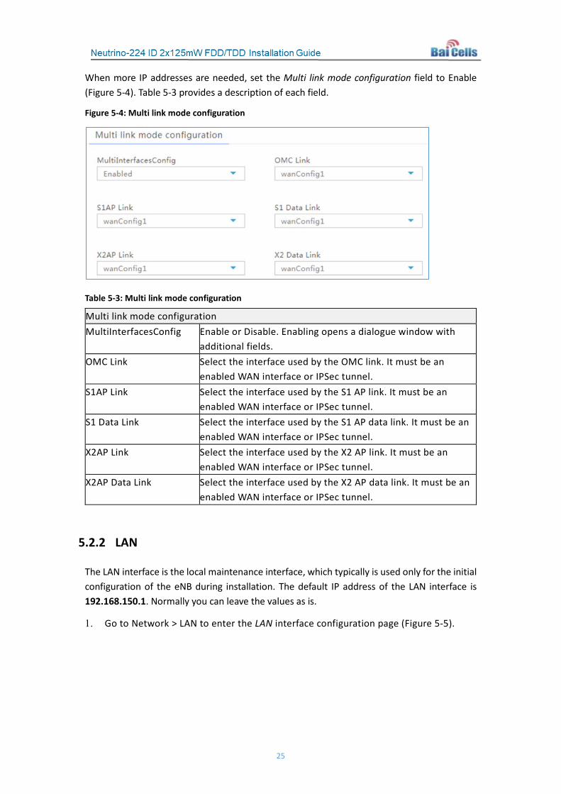
When more IP addresses are needed, set the Multi link mode configuration field to Enable (Figure 5-4). Table 5-3 provides a description of each field.
Figure 5-4: Multi link mode configuration
Table 5-3: Multi link mode configuration
Multi link mode configuration MultiInterfacesConfig Enable or Disable. Enabling opens a dialogue window with
additional fields. OMC Link Select the interface used by the OMC link. It must be an
enabled WAN interface or IPSec tunnel. S1AP Link Select the interface used by the S1 AP link. It must be an
enabled WAN interface or IPSec tunnel. S1 Data Link Select the interface used by the S1 AP data link. It must be an
enabled WAN interface or IPSec tunnel. X2AP Link Select the interface used by the X2 AP link. It must be an
enabled WAN interface or IPSec tunnel. X2AP Data Link Select the interface used by the X2 AP data link. It must be an
enabled WAN interface or IPSec tunnel.
5.2.2 LAN
The LAN interface is the local maintenance interface, which typically is used only for the initial configuration of the eNB during installation. The default IP address of the LAN interface is 192.168.150.1. Normally you can leave the values as is.
1. Go to Network > LAN to enter the LAN interface configuration page (Figure 5-5).

26
Figure 5-5: LAN
2. The LAN interface is enabled by default. If the IP address and Subnet mask need to be changed, input new values in the text fields.
3. If you wish to enable Internet access for the LAN interface, at the LAN Internet Config field select Enabled. This will open a new dialog window, as shown in Figure 5-6. Refer to Table 5-4 for a description of the fields.
NOTE: Modifying the IP address of the LAN interface will interrupt the client computer immediately. You will need to log in again using the new IP address.
Figure 5-6: LAN Internet Config
Table 5-4: LAN Internet
Parameter Name Description
LAN Internet Enable Enable or disable Internet access on the LAN interface. The default is Disabled.
Start IP Address Starting IP address of the DHCP server

27
Parameter Name Description
End IP Address Ending IP address of the DHCP server
dhcpDNS1 DNS address 1 for the DHCP server
dhcpDNS2 DNS address 2 for the DHCP server
dhcpDNS3 DNS address 3 for the DHCP server
4. Click on Save to save the configuration.
5.2.3 Route
Follow the steps below to configure the static route for users with a static IP address. The system supports up to 6 static routes. Defined route tables will appear under Route Status.
1. Go to Network > Route to enter the Route configuration page (Figure 5-7).
Figure 5-7: Route
2. Referring to Table 5-5, input the parameters for the first static route.
Table 5-5: Static Route
Classification Parameter Description
IPV4 ROUTE Default Configuration
onBoot Enable or disable an IPv4 default route. The default is disabled.
netAddr If you enabled an IPv4 default route, set the IP address.

28
Classification Parameter Description
IPV6 ROUTE Default Configuration
onBoot Enable or disable an IPv6 default route. The default is disabled.
netAddr If you enabled an IPv6 default route, set the IP address.
Route Configuration
onBoot On or Off
V6 onBoot Enable or disable IPv6. The default is disabled.
netAddr The target IP address.
Note: The target IP address must be reachable from the original IP address of the WAN interface or VLAN source port.
netmask If it is an IPv4 route, display the parameter.
The subnet mask of target IP address.
prefix If it is an IPv6 route, display the parameter.
The prefix of the IP address.
gw The gateway IP address of the target IP address.
3. Click on Save to complete the static route configuration.
4. Repeat steps 2 and 3 for additional static routes.
5.2.4 Host
This menu is used to configure the host server for the network. You can configure up to 8 DNS servers for the host. Go to Network > Host to enter the Host server configuration page, as shown in Figure 5-8. The fields are described in Table 5-6. After completing the configuration, click on Save.

29
Figure 5-8: Host
Table 5-6: Host
Parameter Name Description Host Name Host server name. Range: 0-63 digits. Time Zone Located time zone of the host server.
Range: -12 to 12. dnsOnBoot Enable or disable Domain Name Server (DNS) function. DNS Address For DNS 1 – 8: Enable or disable the DNS server (#). If enabled, enter the IP
address for the host server. Note: If it is an IPv6 address, select the check box.
5.2.5 IPSec
In the presence of an IP Security (IPSec) gateway, the security protocols are provided in the network layer to ensure the safety of transmissions. The system enables the IPSec function by default and supports the configuration of one IPSec tunnel. Operators can modify the IPSec server configuration based on their specific requirements. Follow the steps in this section to configure IPSec.
1. Go to Network > IPSec to enter the IPSec configuration page, as shown in Figure 5-9.

30
Figure 5-9: IPSec
2. In the IPSec Setting area of the window, check that the IPSec function is set to Enabled (default). If the Enable field is set to Disabled, select Enable to enable the IPSec function. Click on Save to save the IPSec setting.
3. If you wish to enable soft USIM, meaning users can use embedded rather than removable SIM cards, check that the default value of Enabled is selected in the softUsim field.
4. Click on Save to retain the IPSec configuration settings.
5. Under IPSec Tunnel List, click on the display icon under Operate to display the tunnel configuration page. Configure the Basic Setting parameters shown in Figure 5-10 and described in Table 5-7. Select Save to save the changes.
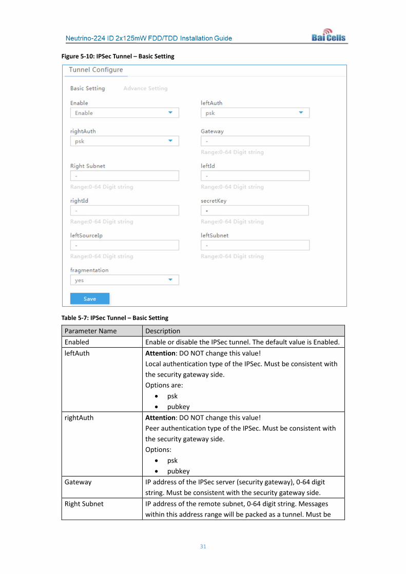
31
Figure 5-10: IPSec Tunnel – Basic Setting
Table 5-7: IPSec Tunnel – Basic Setting
Parameter Name Description Enabled Enable or disable the IPSec tunnel. The default value is Enabled. leftAuth Attention: DO NOT change this value!
Local authentication type of the IPSec. Must be consistent with the security gateway side. Options are:
• psk • pubkey
rightAuth Attention: DO NOT change this value! Peer authentication type of the IPSec. Must be consistent with the security gateway side. Options:
• psk • pubkey
Gateway IP address of the IPSec server (security gateway), 0-64 digit string. Must be consistent with the security gateway side.
Right Subnet IP address of the remote subnet, 0-64 digit string. Messages within this address range will be packed as a tunnel. Must be

32
Parameter Name Description consistent with the security gateway side.
leftId Local ID of the client, 0-64 digit string. Must be consistent with the security gateway side. If absent from the security gateway, leave it empty here.
rightId Peer ID of the server, 0-64 digit string. Must be consistent with the security gateway side. If absent from the security gateway, leave it empty here.
secretKey File name of the private key, 0-64 digit string. The default is clientKey.bin. When auth is psk, the value is the authenticated password.
leftSourceIp Virtual address allocation assigned by the system. If absent, use the local IP address.
leftSubnet The subnet of the virtual address assigned by the system. Range: 0-64 digits.
fragmentation Select the fragmentation mode: • Yes • Accept • Force • No
6. Click on the Advance Setting tab. The fields are shown in Figure 5-11 and described in Table 5-8.
Caution: It is highly recommended that you use the default Advance Setting values. Improper changes may lead to system exceptions.

33
Figure 5-11: IPSec Tunnel – Advance Setting
Table 5-8: IPSec Tunnel – Advance Setting
Parameter Name Description IKE Encryption IKE encryption algorithm.
Options: • aes128 • aes256 • 3des • des
IKE DH Group IKE DH group. Options:
• modp768 • modp1024 • modp1536 • modp2048 • modp4096

34
Parameter Name Description IKE Authentication Authentication algorithm.
Options: • sha1 • sha1_160 • sha256_96 • sha256
ESP Encryption ESP encryption algorithm. Options:
• aes128 • aes256 • 3des • des
ESP DH Group ESP DH group. Options:
• modp768 • modp1024 • modp1536 • modp2048 • modp4096
ESP Authentication ESP Authentication algorithm. Options:
• sha1 • sha1_160 • sha256_96 • sha256
Keylife IPSec SA renegotiation time Time format (s seconds, m minutes, h hours)
IKELifetime IKE SA renegotiation time Time format (s seconds, m minutes, h hours)
RekeyMargin Renegotiation time before the expiry of Ikelifetime (negotiate the IKE SA’s expire time before the expiry of Ikelifetime). Time format (s seconds, m minutes, h hours)
Dpdaction Action to take if there is a gateway exception. Options:
• none • clear • hold • restart
Dpddelay Time interval for sending the dpd detection message. Time format (s seconds, m minutes, h hours).

35
5.2.6 BACKHAUL
Use the BACKHAUL menu (Figure 5-12) to configure the backhaul ping setup for the eNB. For example, you can set it up to ping the OMC, MME, or edge gateway. The fields are described in Table 5-9. Select Save to retain the settings.
Ping results, ping summary, and ping status will display In the lower half of the window..
Figure 5-12: Backhaul
Table 5-9: BACKHAUL
Parameter Name Description
pingEnable Enable or disable the ping function
pingDest Peer IP address
pingCount Count per batch. Range: 1 to 65535
pingInterval (s) Ping interval. Range: 1 to 600
pingTimeout (s) Ping overtime. Range: 1 to 10
pingDatalen Length of ping package. Range: 0 to 65535
pingBatchInterval (s) Interval of every batch ping. Range: 1 to 65535
pingBatchCount Count of batch. Range: 0 to 65535
packetlossAlarmThreshhold (%) Packet loss alarm threshhold - percentage of packet loss to trigger an alarm. Range: 1% to 100%
packetdelayAlarmThreshhold (ms)
Packet delay alarm threshhold, in milliseconds. Range: 1 to 65535 ms
At this time, Neutrino does not support traceroute.

36
5.3 BTS Setting
5.3.1 Security Setting
The Security Setting menu (Figure 5-13) pertains to the LTE encryption algorithms that will be used. For the Neutrino eNB we do not recommend changing any of the default values. The fields are described in Table 5-10.
Caution: DO NOT modify the security parameters; keep the default values.
Figure 5-13: Security Setting
Table 5-10: Security Setting
Parameter Name Description Ciphering Algorithm Encryption algorithm.
Options: • EEA0 (default) • 128-EEA1: 128-EEA1, EEA0 • 128-EEA2: 128-EEA2, EEA0 • 128-EEA3: 128-EEA3, 128-EEA1, EEA0
Integrity Algorithm Integrity protection algorithm. Options:
• 128-EIA1: 128-EIA1, EIA0 (default) • 128-EIA2: 128-EIA2, EIA0 • 128-EIA3: 128-EIA3, 128-EIA1, EIA0
5.3.2 Management Server
This menu is where you identify the Internet address of the management server, e.g., CloudCore OMC. Go to BTS Setting > Management Server (Figure 5-14) to enter the Internet address for the CloudCore server: https://cloudcore.cloudapp.net/cloudcore/, or enter your private network management server address. Click on Save to retain the configuration.

37
Figure 5-14: Management Server
5.3.3 Sync Setting
The LTE technology standards specify timing and synchronization requirements between adjacent eNBs. Synchronizing transmissions helps to avoid eNBs interfering with one another, optimize bandwidth usage, and enhance network capacity.
Go to BTS Setting > Sync Setting (FDD in Figure 5-15, TDD in Figure 5-16). Refer to Table 5-11 for a description of each field. Some of the fields are display only. Select Save to retain the configuration.
Figure 5-15: FDD Sync Setting

38
Figure 5-16: TDD Sync Setting
Table 5-11: Sync Setting
Parameter Name Description TFCS Management Config: primSrc Primary Transport Format Combination (TFC) synchronization
source. Options:
• NTP • PTP • GNSS: only GPS is supported. • NL • EXT_CLK • EXT_PPS • FREE_RUNNING
Sync Mode Synchronization mode. Options:
• FREQ • PHASE (FDD only) • TIME
NL Sync List: rfFrameTimingAdjustment Frame timing offset to the frame boundary of the sync
source. Range: 0 to 999999 (unit = 10 nanoseconds) Default: 0
targetPlmn Target Public Land Mobile Number ID. Supports up to 4

39
PLMN IDs, separated by commas. NL Sync Cell Information (display): Provides the result of NL synchronization; contains cell
information Geographic Location Information (display): Provides the result of GPS synchronization; contains the
geographic location information Satellite Information (display): Provides the result of GPS synchronization; contains the
satellite information
5.3.4 License Management
Use the License Management menu (Figure 5-17) to upload certificate files, such as regulatory approval documents, for the Neutrino eNB you are configuring. Click on Select File, navigate to the file on a local computer, and then select Import License to upload it. After uploading, the license file will display in the license list.
Figure 5-17: License Management
5.4 System
5.4.1 NTP
The operator may use up to 3 Network Timing Protocol (NTP) services to provide correct time-of-day to the eNB. When multiple NTPs are configured, one acts as the master NTP service and the others are for backup.
Go to System > NTP (Figure 5-18). Refer to Table 5-12 for a description of each field. When finished, click on Save to retain the configuration.

40
Figure 5-18: NTP
Table 5-12: NTP
Parameter Name Description onBoot Enable or disable the NTP function Port Port number of the master NTP server. Must be consistent with
the other end. Range: 1 to 65535 Server1 Domain name or IP address of the master NTP server. Must be
consistent with the other end. Server2 Domain name or IP address of the slave NTP server. Must be
consistent with the other end. Server3 Domain name or IP address of the slave NTP server. Must be
consistent with the other end.
5.4.2 Upgrade
The Upgrade menu shown in Figure 5-19 provides the ability for you to upgrade an eNB’s firmware, perform a firmware version rollback (downgrade), or install patches to the current firmware running on the eNB. Most version changes will cause the eNB to reboot, interrupting service to any users connected to the eNB. Plan on executing such changes during a time when there is likely to be few or no active users.

41
Figure 5-19: Upgrade
5.4.2.1 Upgrade Firmware
Refer to Figure 5-19, and follow the steps below to upgrade the version of eNB firmware.
1. From the Baicells website or OMC, download the file with the new version of firmware and save it to a local computer. Be sure the file you select is appropriate for the model of Neutrino eNB being upgraded, e.g., either for FDD or TDD operation.
2. In the eNB GUI, go to System > Upgrade.
3. If you want to retain the current configuration settings on the eNB, click on the check box next to the Attempt to preserve settings field. Otherwise, select Do not Preserve Settings (.IMG) or Upgrade Template (.zip) to reset the eNB to its default configuration or the template settings, respectively.
4. Click on Select File to select the new firmware file.
5. Click on Upload to upload the firmware file to the eNB.
6. Verify the firmware version you uploaded is correct, and then click on Update Now.
7. In the pop-up window, click on PROCEED.
Wait for about 3 minutes while the eNB reboots.
Caution: The reboot action will disrupt eNB service.
The new version of firmware will appear on the Basic Setting > Basic Info page under Software Version.
5.4.2.2 Version Rollback
Refer to Figure 5-19, and follow the steps below to downgrade (roll back) the eNB firmware.
NOTE 1: Only one rollback operation is allowed for each upgrade. Under the rollback permission of the eNB, the firmware can roll back to the version that was installed before the last upgrade. After the rollback, a new rollback will not be permitted until an upgrade has taken place.
NOTE 2: If the previous version is “-”, there is no software version for rollback.

42
1. In the eNB GUI, go to System > Upgrade.
2. Click on Click Rollback.
3. In the pop-up window, click on OK.
Wait for about 3 minutes while the eNB reboots.
Caution: The reboot action will disrupt eNB service.
The version of firmware after rollback will display on the Basic Setting > Basic Info page under Software Version.
5.4.3 Backup
The Backup menu is shown in Figure 5-20. Through this menu you can perform the following:
• Import configuration files
• Back up the current eNB configuration
• Back up eNB log files and crash files
• Restore all of the eNB’s default configuration settings
How to use each of these functions is covered in this section.
Figure 5-20: Backup
5.4.3.1 Import Configuration Files
Follow the steps below to import eNB configuration files - e.g., to create a new eNB using the configuration from an existing eNB.

43
1. First, make sure you have the configuration file that you want to upload to the eNB on a local computer.
2. In the eNB GUI go to System > Backup, as was shown in Figure 5-20.
3. Under Import Configuration Files, click on Select File and navigate to the configuration file on the local computer. Click on Upload to upload the configuration file.
4. Click on Import the configuration file to import the file to the eNB.
5.4.3.2 Backup Current Configuration
1. In the eNB GUI go to System > Backup, as was shown in Figure 5-20.
1. Under Backup Current Configuration, click on Get Backup Files.
2. In the pop-up Download dialog window, select a file path where you want to save the current configuration file on the local computer.
5.4.3.3 Backup Log Files
1. In the eNB GUI go to System > Backup, as was shown in Figure 5-20.
2. Under Backup Log Files, click on Get Log Files.
3. In the pop-up Download dialog window, select the file path where you want to save the log files on the local computer.
5.4.3.4 Backup Crash Logs
1. In the eNB GUI go to System > Backup, as was shown in Figure 5-20.
2. Under Backup Crash Logs, click on Get Crash Logs.
3. In the pop-up Download dialog window, select the file path where you want to save the crash log files on the local computer.
5.4.3.5 Restore Default Configuration
Caution: Restore will cause the eNB to reboot immediately, disrupting service.
1. In the eNB GUI go to System > Backup, as was shown in Figure 5-20.
2. Under Restore Default Configuration, click on Restore Settings.
3. In the pop-up Download dialog window, click on OK. The eNB will reboot immediately.
It will take about 3 minutes for the eNB to complete the reboot.
5.4.4 Password
The Password menu allows you to change the eNB administrator password. To configure a new password, follow the steps below.
1. In the eNB GUI go to System > Password.

44
2. Enter the current password in the Old Password field; enter the new password in the New Password field; and enter the new password again in the Confirm Password field.
3. Click on Save to save the changes.
5.4.5 CertStore
The Certification Store (CertStore) menu (Figure 5-21) is a place within the eNB database for storing authorization credentials such as HTTPS, TR-069, IPSec Certificate Authorities (CA).
NOTE: For private IPSec, only the *.der files are required. The *.bin files are generated automatically and do not need to be included.
Figure 5-21: CertStore
In the eNB GUI go to System > CertStore. For each type of certificate, click on Select File to navigate to the certificate file on a local computer. Once you find the file, click on Upload.
After the certificate file is upload to the eNB, you can view the certificate file in the Certificate List. Use the Export icon to download a certificate file. Use the Trash icon to delete a certificate file.
5.5 LTE Setting
Caution: Baicells recommends that you DO NOT modify these advanced LTE parameters; keep the default values.
The LTE Setting parameters are important for efficient wireless network operation (Figure 5-22). The information pertaining to the LTE Setting menu is broken into two sections: “Neighbor Cells & Mobility” (section 5.18.1), and “Other LTE Settings” (section 5.18.2).
It is a good idea to review all of the LTE Setting information to understand how the configuration settings relate.

45
Important: If you make any changes to the LTE Setting parameters, you must reboot the eNB for the new configuration to take effect. A reboot action will disrupt service.
Figure 5-22: LTE Setting
5.5.1 Neighbor Cells & Mobility
5.5.1.1 Planning
Under LTE Setting you will establish the neighboring eNBs operating in the same geographical area as the eNB that you are configuring. This information is completed for each eNB so that the eNBs collectively work well with one another to handle mobile users and to balance the traffic load.
Under the LTE Setting menu, you will (a) configure the neighboring eNBs’ frequencies and identify each eNB running on that frequency; (b) configure the current eNB’s mobility parameters; and (c) examine the current eNB’s advanced settings. Note that many, if not all, of the advanced settings should be left with their default values; any modification should be determined only by experienced wireless professionals.
Additional LTE Setting sub-menus are explained in section 5.17.2 Other LTE Settings.
Important: Make sure the current and neighboring eNBs are GPS enabled and synchronized.
5.5.1.2 Identify Neighboring eNBs
Potentially, there are 3 types of neighboring eNBs based on the type of technology they use to operate:
• Other LTE eNBs
• 3G mobile eNBs, which use Wideband Code Division Multiple Access (WCDMA)
• Global System for Mobile (GSM) eNBs
The LTE Setting menu provides a sub-menu for each of these types of eNBs.

46
For each type of neighboring eNB, you will first add the neighbor frequency settings via the Neigh Freq List, and then you will add the cell information associated to the frequencies via the Neigh Cell List.
You can configure the Neigh Cell List for both inter-frequency (between different frequencies) and intra-frequency (within the same frequency) neighboring eNBs. For inter-frequency cells, you must add the neighbor inter-frequency settings in the Neigh Frequency List before you try to add the neighbor inter-frequency cell (eNB) information. Conversely, if you need to delete a neighbor inter-frequency record, you must first delete the neighbor inter-frequency cells (eNBs) associated to it.
For an intra-frequency neighbor cell, meaning a neighbor eNB operating on the same frequency as the eNB you are configuring, you do not need to configure the Neigh Freq List, but you do need to configure the Neigh Cell List.
5.5.1.3 LTE Freq/Cell
Using the LTE Freq/Cell sub-menu, you can configure parameters related to how adjacent eNBs operating with LTE technology work with the Baicells Neutrino eNB that you are configuring. In other words, you will define for the Neutrino eNB how to coordinate with any neighboring LTE eNBs. Up to 8 LTE neighbor frequencies and 32 LTE neighbor cells can be configured.
5.5.1.3.1 Neigh Freq List
1. In the eNB GUI go to LTE Setting > LTE Freq/Cell (Figure 5-23).
Figure 5-23: LTE Freq/Cell
2. Under Neigh Freq List, click on the Add icon to add the neighboring LTE eNBs’
frequencies (up to 8). The fields are shown in Figures 5-24 and 5-25, and described in Table 5-13. Click on Save after setting the values.

47
Figure 5-24: LTE Neigh Freq Settings (1 of 2)
Figure 5-25: LTE Neigh Freq Settings (2 of 2)

48
Table 5-13: Neighbor LTE eNB Frequencies
Parameter Name Description eutraCarrierArfcn Frequency point of the neighbor frequency.
Range: 0 to 65535 meansBandwidthForEarfcn This field is used to indicate the maximum allowed
measurement bandwidth in number of resource blocks on a carrier frequency. Options:
• 0 = 6 resource blocks 1 = 15 resource blocks 2 = 25 resource blocks 3 = 50 resource blocks 4 = 75 resource blocks 5 = 100 resource blocks
Refer to 3GPP 36. 104 Transmission Bandwidth Configuration. presenceAntennaPort1 This field is used to indicate whether or not all of the
neighboring cells use antenna port 1. Options:
• TRUE = At least 2 cell-specific antenna ports are used in all neighboring cells
• FALSE = Neighboring cells all use antenna port 1 neighborCellConfig Identifies the configuration of MBSFN and TDD uplink/downlink
subframes of the neighbor cell. Range: 0-3 or 0-5 depending on software version. For more information, refer to TS 36.331 NeighCellConfig.
qOffsetFreq Offset frequency for quality evaluation of the cell qRxLevelMin Minimum access level. When the receive signal power of a UE
is larger than this threshold, the UE can connect to the cell. Range: -70 to -22
pMax Maximum transmit power that UEs are allowed to use in the uplink. The purpose of this value is to limit the transmit power of UEs within this cell. Range: -127 or -30 to 33
tReselectionEutra The length of the delay timer for cell reselection when a UE is in normal mobility state. Refer to TS 36.331 and 36.304 for more information on MobilityStateParameters and UE mobility state evaluation. Range: 0 to 7 seconds
tReselectionEutraSFMedium This value is part of the calculation related to the TreselectionEUTRA speed-dependent scaling factor. When a neighbor cell is ranked as better than the serving cell, based on RSRP, for a certain period of time (tReselectionEutra) the UE in medium mobility state will be handed off to the neighbor cell.

49
Parameter Name Description tReselectionEutraHigh This value is part of the calculation related to the
TreselectionEUTRA speed-dependent scaling factor. When a neighbor cell is ranked as better than the serving cell, based on RSRP, for a certain period of time (tReselectionEutra) the UE in high mobility state will be handed off to the neighbor cell.
Reselection Thresh High The reselection threshold for higher priority inter-band frequencies. This parameter represents the access threshold level at which a UE will leave the serving cell and reselect another cell at the target frequency, given that the target frequency cell has a cell reselection priority higher than the serving one. Range: 0 to 31
RsSelection Thresh Low The reselection threshold for lower priority inter-band frequencies. This parameter represents the access threshold level at which a UE will leave the serving cell and reselect another cell at the target frequency, given that the target frequency cell has an absolute priority lower than the serving one. Range: 0 to 31
Reselection Priority Priority of the reselection to cells at this frequency. Range: 0 to 7
qQualMinR9 The maximum uplink transmitted power that UEs are allowed. The parameter is used to limit the transmitted power in the cell. Range: -1 or -34 to -3
threshxHighqR9 High RSRQ threshold of priority reselection. Range: 0 to 31
threshxLowqR9 Low RSRQ threshold of priority reselection. Range: 0 to 31
csgPhyCellIdStart The starting value of PCI used for Closed Subscriber Group (CSG) close mode. Range: 0 to 503
csgPhyCellIdRange The number of PCIs used for CSG close mode multibandInfoList The list of multi frequencies, used to identify that a frequency
point belongs to multi bands. Range: 0-2^32
openPhyCellStart The starting value of PCI used for CSG open mode. Range: 0 to 503
openPhyCellRange The number of PCIs used for CSG open mode hybridPhyCellIdStart The starting value of PCI used for CSG hybrid mode.
Range: 0 to 503 hybridPhyCellIdList The number of PCIs used for CSG hybrid mode

50
5.5.1.3.2 Neigh Cell List
1. In the eNB GUI go to LTE Setting > LTE Freq/Cell.
2. Under Neigh Cell List, click on the Add icon to add the neighboring LTE cells (up to 32). The fields are shown in Figure 5-26 and described in Table 5-14. Click on Save after entering the information.
Figure 5-26: LTE Neigh Cell Settings
Table 5-14: Neigh Cell List
Parameter Name Description PLMN PLMN that the neighbor cell belongs to. Must be a 5-
or 6-digit number. cid Cell ID of the neighbor cell.
Range: 0 to 268435455 eutraCarierArfcn Frequency point of the neighbor cell.
Range: 0 to 65535 phyCellId PCI of the neighbor cell.
Range: 0 to 503 qOffset Frequency offset of the neighbor cell cio Cell offset of the neighbor cell

51
Parameter Name Description rsTxPower Reference transmitted power of the neighbor cell Blacklisted BlackList identifier numPlmnId Number of shared PLMNs.
Range: 0 to 5 plmnIdlist The list of shared PLMNs, each separated with a
comma (,). Range: 0 to 64
rsrp The measurement value of RSRP csgID CSG ID nrStatus Neighbor management identity rsrq RSRQ of the cell TAC TAC of the neighbor cell.
Range: 0 to 65535 broadcastStatus Whether or not to broadcast this neighbor cell in
system messages dahoIndication Database Assisted Handover (DAHO) flag – indicates if
the cell is reserved as a default target cell for mobility. Options: 0 = Not a DAHO cell (default) 1 = Is a DAHO cell
accessMode Access mode of the cell: 0 = ClosedAccess 1 = HybridAccess 2 = OpenAccess 3 = OpenFemtoAccess
prachConfigurationIndex Configuration index for random access prachRootSquenceIndex Root sequence index of random access preamble prachZeroCorrelationZoneConfig Zero correlation sequence configuration of the
random access preamble prachFreqencyOffest Frequency offset of random access prachHighSpeedFlag High speed flag of random access sonDiscovered SON ANR detection flag multibandInfoList The list of multi frequencies, used to identify that a
frequency point belongs to multiple bands. Range: 0-2^32
5.5.1.4 3G Freq/Cell
A 3G cell uses Wideband Code Division Multiple Access (WCDMA). Use the 3G Freq/Cell sub-menu to configure how adjacent eNBs operating with 3G mobile technology work with the Baicells Neutrino eNB you are configuring. Up to 12 3G neighbor frequencies and 32 3G neighbor cells can be configured.

52
5.5.1.4.1 Neigh Freq List
1. In the eNB GUI go to LTE Setting > 3G Freq/Cell (Figure 5-27).
Figure 5-27: 3G Freq/Cell
2. Under Neigh Freq List, click on the Add icon to add the neighboring 3G eNBs’ frequencies (up to 12). Each field is described in Table 5-15. Click on Save after setting the values.
Table 5-15: Neigh Freq List
Parameter Name Description utraCarrierArfcn Frequency point of the neighbor frequency qRxLevMin Minimum access level. Only if the received signal power
measured by the UE is higher than this threshold, can the UE connect to this cell.
qQualMin The threshold for the lowest access. Range: -24 to 0.
Reselection Priority Priority of the reselection to cells at this frequency threshXHigh Reselection threshold for higher priority inter-band
frequencies. This parameter represents the access threshold level at which the UE will leave the serving cell and reselect another cell at the target frequency, given that the target frequency cell has a cell reselection priority higher than the serving one
threshXLow Reselection threshold for lower priority inter-band frequencies. This parameter represents the access threshold level at which the UE will leave the serving cell and reselect another cell at the target frequency, given that the target frequency cell has an absolute priority lower than the serving one.
pMaxUtra Maximum transmit power a UE is allowed to use in the uplink. The purpose is to limit the transmit power of UEs within this cell.
threshServingHighqR9 High RSRQ threshold of priority reselection. Range: 0 to 31.
53
Parameter Name Description threshServingLowqR9 Low RSRQ threshold of priority reselection.
Range: 0 to 31.
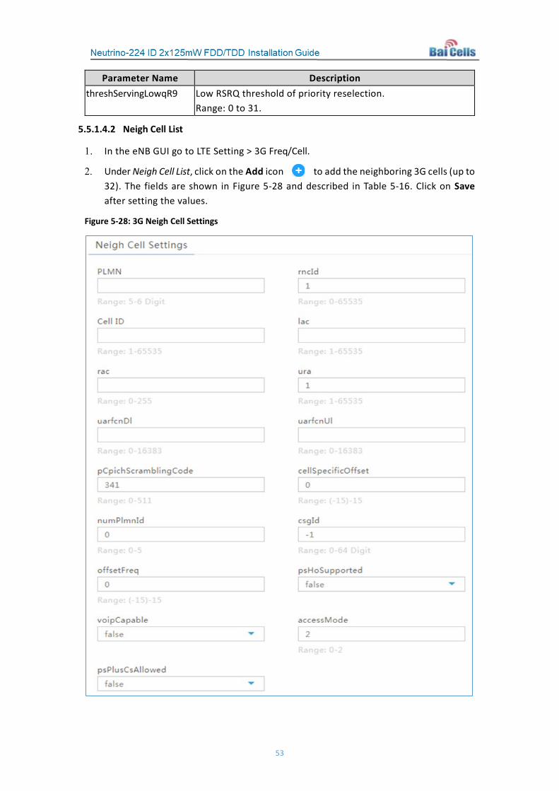
5.5.1.4.2 Neigh Cell List
1. In the eNB GUI go to LTE Setting > 3G Freq/Cell.
2. Under Neigh Cell List, click on the Add icon to add the neighboring 3G cells (up to 32). The fields are shown in Figure 5-28 and described in Table 5-16. Click on Save after setting the values.
Figure 5-28: 3G Neigh Cell Settings

54
Table 5-16: Neigh Cell List
Parameter Name Description PLMN PLMN that the neighbor cell belongs to. Must be a 5- or 6-
digit number. rncId ID of the neighbor cell’s RNC.
Range: 0 to 65535 Cell ID Cell ID of the neighbor cell.
Range: 1 to 65535 lac Location area code (LAC) of the neighbor cell.
Range: 1 to 65535 rac Radio Admission Control (RAC) of the neighbor cell.
Range: 0 to 255 ura UMTS register area.
Range: 1 to 65535 uarfcnDI UARFAN for download.
Range: 0 to 16383 uarfcnUI UARFAN for upload.
Range: 0 to 16383 pCpichScramblingCode Scrambling code for main CPICH.
Range: 0 to 511 cellSpecificOffset Offset for cell quality measurement.
Range: -15 to 15 numPlmnId Number of secondary PLMNs used for MOCN.
Range: 0 to 5 csgId CSG ID.
Range: 0 to 64 digits offsetFreq Frequency offset (delete).
Range: -15 to 15 psHoSupported Whether or not this neighbor supports PS domain switchover voipCapable VoIP capable flag for the neighbor cell accessMode Access mode of the cell:
0 = ClosedAccess 1 = HybridAccess 2 = OpenAccess
psPlusCsAllowed Switchover enabled flag
5.5.1.5 GSM Freq/Cell
Use the GSM Freq/Cell sub-menu to configure how adjacent eNBs operating with GSM technology work with the Baicells Neutrino eNB that you are configuring. You will define for the Neutrino eNB how to deal with any neighboring GSM eNBs. Up to 12 GSM neighbor frequencies and 32 GSM neighbor cells can be configured.

55
5.5.1.5.1 Neigh Freq List
1. In the eNB GUI go to LTE Setting > GSM Freq/Cell (Figure 5-29).
Figure 5-29: GSM Freq/Cell
2. Under Neigh Freq List, click on the Add icon to add the neighboring GSM eNBs’ frequencies (up to 12). Each field is described in Table 5-17. Click on Save after setting the values.
Table 5-17: Neigh Freq List
Parameter Name Description qRxLevMin Minimum access level. Only when the received signal power
measured by the UE is higher than this threshold will the UE be allowed to connect to this cell.
Reselection Priority Priority of the reselection to cells at this frequency threshXHigh Reselection threshold for higher priority inter-band frequency.
This parameter represents the access threshold level at which the UE will leave the serving cell and reselect another cell at the target frequency, given that the target frequency cell has a cell reselection priority higher than the serving one
threshXLow Reselection threshold for lower priority inter-band frequency. This parameter represents the access threshold level at which the UE will leave the serving cell and reselect another cell at the target frequency, given that the target frequency cell has an absolute priority lower than the serving one.
bandIndicator DCS1800/PSC1900 frequency band indicator bcchArfcn ARFCN for GSM neighbor frequency nccPermitted Permitted NCC of the neighbor cell pMaxGeran The allowed max upload transmitted power arfcnSpacing ARFCN interval of frequency point list. numOfFollowingArfcns ARFCN number of frequency point list

56
5.5.1.5.2 Neigh Cell List
1. In the eNB GUI go to LTE Setting > GSM Freq/Cell (shown in Figure 5-29).
2. Under Neigh Cell List, click on the Add icon to add the neighboring GSM cells (up to 32). Each field is described in Table 5-18. Click on Save after setting the values.
Table 5-18: Neigh Cell List
Parameter Name Description enable Determines whether or not to enable the neighbor cell PLMN PLMN that the neighbor cell belongs to lac Location area code of the neighbor cell ci Cell ID of the neighbor cell bandIndicator Band indicator of the neighbor cell bcch Arfcn ARFCN of the neighbor cell bsic eNodeB identification code of the neighbor cell networkControlOrder Options:
00 (NC0): UE reselects the cell automatically 01 (NC1): UE sends a measurement report to the network
and reselects the cell automatically 10 (NC2): UE sends measurement report to the network,
but does not reselect the cell automatically. The reselection is controlled by the network.
11 (RESET) dtmSupported Determines whether or not to support dual transmission mode
(DTM) dtmHoSupported Determines whether or not to support the switchover of DTM voipCapable VoIP capable flag dahoIndication Default switchover target cell flag cellSpecificOffset Cell access mode: ClosedAccess/HybridAccess/OpenAccess rac Radio Admission Control (RAC) rssi Measurement value of RSSI nrStatus Locked flag for neighbor cell. “True” indicates locked. hoStatus Switchover of enabled status sonDiscovered SON ANR detection flag psHoSupported Packet Switched (PS) switchover enabled flag
5.5.1.6 Mobility Parameter
The Mobility Parameter menu pertains to how roaming UE sessions are handled between different eNBs in the same service area. When a UE is actively connected to an eNB, the current eNB is referred to as the serving eNB or cell. The other eNBs in the area are referred to as either neighbor or target eNBs or cells.

57
The process of a device moving from cell to cell and changing over from its serving eNB to a neighbor (target) eNB is called handoff or handover*. The UE exchanges information with its serving eNB to perform cell selection and reselection based on parameters which you will set for each eNB. Refer to Figure 5-30.
*NOTE: The terms handoff and handover are used interchangeably in LTE.
Figure 5-30: Handoff
What the UE measures that determines cell selection and reselection is the Reference Signal Received Power (RSRP) of the serving as well as neighboring eNBs. The measurements are sent periodically to the serving eNB, which then determines if the UE would be better served by an adjacent eNB.
The default settings in the Mobility Parameter sub-menus (Figure 5-31) can be adapted to most situations. Many of the mobility settings should be left with their default values. Any modification should be determined only by experienced wireless professionals.
In terms of LTE to LTE handoff, only the A1, A3, A5, Measurement Control, Cell Selection Parameter, and Cell ReSelection Parameter fields are used.
If the serving eNB determines that more than one adjacent eNB meets the RSRP event thresholds, the Cell Reselection settings will determine to which adjacent eNB the serving eNB will hand off.
You will configure these mobility parameters for every adjacent eNB. To open one of the threshold areas in the window, simply click on the heading, e.g., A1 Event Threshold, to display the configuration fields. Table 5-19 describes each field. Click on Save to save the configuration data.

58
Figure 5-31: Mobility Parameter
Table 5-19: Mobility Parameter
Parameter Name Description A1 Event Threshold: LTE A1 RSRP Threshold The LTE A1 event is triggered when the serving cell’s Reference
Signal Received Power (RSRP) becomes better than the A1 threshold. The A1 event can be used to turn off certain inter-cell measurements. Range is 0-97 (integer). Default value is 90. In this example, the recommended value is 45 (integer), which means -140 dBm + 45 = -95 dBm.
A2 Event Threshold: LTE A2 RSRP Threshold The LTE A2 event is triggered when the serving cell’s Reference Signal
Received Power (RSRP) becomes worse than the A2 threshold. Range is 0-97 dB. In this example, the recommended value is 40 (integer), which means -140 dBm + 40 = -100 dBm.
A3 Event Threshold (Figure 5-32): LTE A3 Offset The offset value to be used in the EUTRA measurement report
triggering condition for event A3, as specified in 3GPP 36.331 6.3.5. Range: -30 to 30
A3 Offset Anr A3 event triggering threshold for UE Automatic Neighbor Relation (ANR) measurements of intra-frequency neighbors. Range: -30 to 30
A4 Event Threshold (Figure 5-33): A4 RSRP Threshold The threshold to be used in the EUTRA measurement report

59
triggering condition for even A4, as specified in 3GPP 36.331 6.3.5. Range: 0 to 97
A5 Event Threshold (Figure 5-34): Inter-Freq Handover A5 RSRP Threshold1
The LTE A5 event is triggered when the serving cell becomes worse than Threshold 1 while a neighbor cell becomes better than Threshold 2. Range is 0-97 (integer). In this example, the recommended value is 40 (integer), which equals -140 dBm + 40 = -100 dBm.
Inter-Freq Handover A5 RSRP Threshold2
Range is 0-97 (integer). In this example, the recommended value is 45 (integer), which equals -140 dBm + 45 = -95 dBm.
Measurement Control Parameter (Figure 5-35): fc filterCoefficient - specifies the filtering coefficient for RSRP
measurements used to calculate average measurement results, as specified in TS 36.331 [5.5.3.2]. Options: 0, 1, 2, 3, 4, 5, 6, 7, 8, 9, 11, 13, 15, 17, 19
Report Interval Measurement result report interval, in milliseconds. Options: 120 (default), 240, 480, 640, 1024, 2048, 5120, 10240, 60000, 360000, 720000, 1800000, 3600000
Hysteresis Hysteresis is a parameter used within the entry and leave condition of an event triggered reporting condition. The actual value is IE value * 0.5 dB, as specified in 3GPP 36.331 6.3.5. Range: 0 to 30 dB
Time To Trigger Specifies the value range used for the time to trigger parameter, which concerns the time during which specific criteria for the event need to be met in order to trigger a measurement report.
B2 Event Threshold (Figure 5-36): B2 RSRP Threshold1 Threshold parameter 1 of the UTRA Time Domain Scheduling
(TDS) B2 event. Range: 0 to 97
UTRA B2 IRAT Threshold2 Threshold parameter 2 of the UTRA TDS B2 event. Range: -5 to 91
GERAN B2 IRAT Threshold2
Threshold parameter 2 of the GSM Edge Radio Access Network (GERAN) B2 event Options: 0-63 (integer) Default: 10
Hysteresis This parameter refers to the hysteresis of the different system measurements, in dB. The actual value will be the configured value x 0.5. Range: 0 to 30
Time To Trigger Trigger time of different system events, in milliseconds. Options: 0, 40, 64, 80, 100, 128, 160, 256, 320, 480, 512, 640, 1024, 1280, 2560, 5120 ms

60
Default: 0 Cell Selection Parameter (Figure 5-37): Qrxlevmin(dBm) Used to indicate cell selection/reselection based on the
required minimum received RSRP level in the EUTRA cell. The actual value will be Qrxlevmin = IE value * 2 [dBm], as specified in 36.304 [4]. Range: -70 dBm to -22 dBm Default: -60 dBm
Qrxdevminoffset This parameter defines the offset with respect to QrxLevMin when performing periodic searches for a higher priority PLMN while camped normally in a Visited PLMN (VPLMN). Actual value will be Qrxlevminoffset = IE value * 2. A value of -1 is used as an indicator that the parameter is optional and will not be sent in the SIB. Refer to 3GPP TS 36.304. Range: 1 to 8 dB Default: 1 dB
Cell ReSelection Parameter (Figure 5-38): S-IntraSearch Threshold for intra-frequency measurements. A value of -1 is
used to indicate the parameter is optional and will not be sent in the SIB. The actual value is IE value * 2 dB.Refer to 3GPP TS 36.304. Range: 0-31 Default: 31
S-NonIntraSearch Threshold for inter-frequency and inter-RAT measurements with lower or equal priority. A value of -1 is used to indicate the parameter is optional and will not be sent in the SIB. The actual value is IE value * 2 dB. Refer to 3GPP TS 36.304. Range: 0-31 Default: 31
QrxlevminSib3 Minimum receive power for the reselection to occur. The actual value is IE value * 2 dBm. Range: -70 to -22 (integer) Default: -60
Reselection Priority Absolute priority of the E-UTRAN serving carrier frequency used in the inter-frequency and inter-RAT cell reselection procedure. Range: 0 to 7 (integer) Default: 7
ThreshServingLow Threshold for selection to cells of lower priority. The actual value is IE value * 0.5 dB. Range: 0-31 Default: 6
pMax Maximum power that a UE can transmit in this cell, in dBm. Range: -30 to 33 dBm

61
Qhyst Compensation for the serving cell in the reselection evaluation. See parameter Qhyst in 3GPP 36.304. Range: 0-6, 8,10,12,14,16,18,20,22,24 dB Default: 3 dB
Allowed Meas BW Measurement bandwidth allowed. Options: Null, 1.4 MHz, 3 MHz, 5 MHz, 10 MHz, 15 MHz, or 20 MHz Default: 20 MHz
Additional Measurement Parameter (Figure 5-39): mobilityType Designated mobility type of the UE’s consequent action after
the measurement event reporting. Options: Blind_redirect Irat_data Irat_voice
measEvent Defines the event type of measurement report. Options: EVENT_A2 EVENT_B2 - only mapping to Irat_voice
eutranThresholdRsrp RSRP threshold to be used in EUTRA measurement report triggering condition for events A2 and A5. Range: 0 to 97
eutranThresholdRsrq RSRQ threshold to be used in EUTRA measurement report triggering condition for events A2 and A5. Range: 0 to 34
Hysteresis Hysteresis value applied to entry and leave condition of a report triggering event. The actual value will be the configured value x 0.5. Refer to 3GPP 36.331 6.3.5. Range: 0 to 30
Time To Trigger Concerns the time during which specific criteria for the event need to be met in order to trigger a measurement report. Refer to 3GPP 36.331 6.3.5. Options: 0, 40, 64, 80, 100, 128, 160, 256, 320, 480, 512, 640, 1024, 1280, 2560, 5120 ms Default: 0 ms
eutranTriggerQuantity The quantities used to evaluate the triggering condition for the event for the .Reference Signal Received Power (RSRP) and Reference Signal Received Quality (RSRQ) value, as specified in 3GPP 36.331 6.3.5. Options: RSRP RSRQ
A2reportQuantity Measurement quantities to be included in the A2 measurement report.
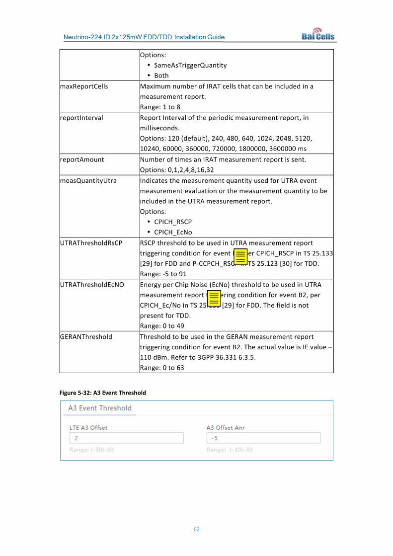
62
Options: SameAsTriggerQuantity Both
maxReportCells Maximum number of IRAT cells that can be included in a measurement report. Range: 1 to 8
reportInterval Report Interval of the periodic measurement report, in milliseconds. Options: 120 (default), 240, 480, 640, 1024, 2048, 5120, 10240, 60000, 360000, 720000, 1800000, 3600000 ms
reportAmount Number of times an IRAT measurement report is sent. Options: 0,1,2,4,8,16,32
measQuantityUtra Indicates the measurement quantity used for UTRA event measurement evaluation or the measurement quantity to be included in the UTRA measurement report. Options: CPICH_RSCP CPICH_EcNo
UTRAThresholdRsCP RSCP threshold to be used in UTRA measurement report triggering condition for event B2, per CPICH_RSCP in TS 25.133 [29] for FDD and P-CCPCH_RSCP in TS 25.123 [30] for TDD. Range: -5 to 91
UTRAThresholdEcNO Energy per Chip Noise (EcNo) threshold to be used in UTRA measurement report triggering condition for event B2, per CPICH_Ec/No in TS 25.133 [29] for FDD. The field is not present for TDD. Range: 0 to 49
GERANThreshold Threshold to be used in the GERAN measurement report triggering condition for event B2. The actual value is IE value – 110 dBm. Refer to 3GPP 36.331 6.3.5. Range: 0 to 63
Figure 5-32: A3 Event Threshold

63
Figure 5-33: A4 Event Threshold
Figure 5-34: A5 Event Threshold
Figure 5-35: Measurement Control Parameter
Figure 5-36: B2 Event Threshold
Figure 5-37: Cell Selection Parameter

64
Figure 5-38: Cell ReSelection Parameter
Figure 5-39: Additional Measurement Parameter
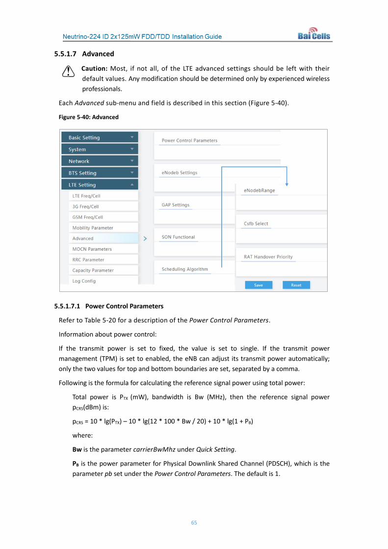
65
5.5.1.7 Advanced
Caution: Most, if not all, of the LTE advanced settings should be left with their default values. Any modification should be determined only by experienced wireless professionals.
Each Advanced sub-menu and field is described in this section (Figure 5-40).
Figure 5-40: Advanced
5.5.1.7.1 Power Control Parameters
Refer to Table 5-20 for a description of the Power Control Parameters.
Information about power control:
If the transmit power is set to fixed, the value is set to single. If the transmit power management (TPM) is set to enabled, the eNB can adjust its transmit power automatically; only the two values for top and bottom boundaries are set, separated by a comma.
Following is the formula for calculating the reference signal power using total power:
Total power is PTX (mW), bandwidth is Bw (MHz), then the reference signal power pCRS(dBm) is:
pCRS = 10 * lg(PTX) – 10 * lg(12 * 100 * Bw / 20) + 10 * lg(1 + PB)
where:
Bw is the parameter carrierBwMhz under Quick Setting.
PB is the power parameter for Physical Downlink Shared Channel (PDSCH), which is the parameter pb set under the Power Control Parameters. The default is 1.

66
Table 5-20: Power Control Parameters
Parameter Name Description Total Tx Power Transmit power of the reference signal Power Ramping Power ramping value used to determine PRACH transmission
power when re-transmitting the preamble during a Random Access Procedure, in dB. Options: 0, 2, 4, or 6 dB
Preamble Init Target Power
Initial power of PRACH, in dBm. Options: -120,-118,-116,-114,-112,-110,-108,-106,-104,-102,-100,-98,-96,-94,-92,-90 dBm
Po_nominal_pusch Parameter:
)1(PUSCH O_NOMINAL_P
See TS 36.213 [5.1.1.1]. This field is applicable for non-persistent scheduling only.
Range: -126 to 24 dBm Po_nominal_pucch
Parameter: PUCCH O_NOMINAL_P
See TS 36.213 [23, 5.1.2.1].
Range: -127 to -96 dBm alpha Power control loss compensation factor, which controls the UE
power. Options:0,40,50,60,70,80,90,100
Target ul sinr Desired Signal-to-Interference-Plus-Noise Ratio (SINR) level at certain path loss. When the UE’s path loss is determined and the uplink SINR detected by L1 is below this target value, the eNB will increase the transmit power of the UE by sending the TPC. Range: 0-255, representing -64 dBm to 63.5 dBm in steps of 0.5 dBm
pa Power boosting the reference signal is allocated to UEs on a dynamic and opportunistic basis. The relative PDSCH power is determined by two computed parameters: PA and PB. Traffic loading must be balanced with controlling interference to neighboring cells. PA is defined in 3GPP 36.213, chapter 5.2 Downlink power allocation. Options: -600, -477, -300, -177, 0, 100, 200, or 300
pb See description for pa. Options: -600, -477, -300, -177, 0
5.5.1.7.2 eNodeB Settings
Refer to Table 5-21 for a description of the eNodeB Settings.

67
Table 5-21: eNodeB Settings
Parameter Name Description eNodeb Name Name the eNB you are configuring, using 0-48 characters
comprised of letters, numbers, and special characters. CellType Options: 0 or 1 s1ConnectionMode S1 connection to MME.
Options: one or all relOfMme S1 connection protocol version.
Options: 0, 1, or 2 accessMode Options:
• ClosedAccess • HybridAccess • OpenAccess
5.5.1.7.3 GAP Setting
Refer to Table 5-22 for a description of the GAP Setting fields.
Table 5-22: GAP Setting
Parameter Name Description siGapEnable Enable or disable the GAP function eutranGapOffsetType GAP type of the LTE measurement.
Options: • 0 (gp0) • 1 (gp1)
geranGapOffsetType GAP type of the GSM measurement. Options:
• 0 (gp0) • 1 (gp1)
cdma2000GapOffsetType GAP type of the CDMA measurement. Options:
• 0 (gp0) • 1 (gp1)
triggerQuantityForBlock Trigger quantity of the mobility measurement of the UE caused by the cell operation, for example, cell block, load balance, etc.
a4ThresholdRsrpForBlock RSRP threshold used by the A4 event when there is a mobility measurement of the UE caused by the cell operation, for example, cell block, load balance, etc.
a4ThresholdRsrqForBlock RSRQ threshold used by the A4 event when there is a mobility measurement of the UE caused by the cell operation, for example, cell block, load balance, etc.

68
5.5.1.7.4 SON Setting
Refer to Figure 5-41 and to Table 5-23 for a description of the SON Setting fields.
Figure 5-41: SON Functional
Table 5-23: SON Setting
Parameter Name Description PCI Selfconfig Enable or disable SON function.
Default: Enabled lteSonNLEnabled Enable or disable the Network Listening (NL)
function. lteNLAssistedNeighborDiscoveryEnabled
Enable or disable the assisted NL neighbor discovery.
ueAssistedNeighborDiscovery Enable or disable the assisted UE neighbor discovery.
activeNeighborManagement Activate or deactivate the neighbor management. pciCollisionDetectionResolution Enable or disable PCI collision detection resolution. pciConfusionResolutionEnabled Enable or disable PCI confusion resolution. x2ConnectionEnabled Enable or disable the X2 connection function. lteSonPersistenceDetermination Enable or disable the SON persistence
determination function.

69
clearPersistence Enable or disable the SON persistence history data clear function.
tpmEnabled Enable or disable the TPM function. tpmMOEnabled Enable or disable the Management Object (MO)
function.
5.5.1.7.5 Scheduling Algorithm
The Scheduling Algorithm fields are important for smooth RF operation and can impact key performance indicators such as cell throughput, cell edge users, Voice Over IP (VoIP) capacity, and data Quality of Service (QoS). The most common scheduling strategies used are listed below:
QoS - Algorithm based on QoS
PFS – Proportionally Fair Scheduling (PFS) balances between channel quality and user fairness, where both cell throughput and user fairness are considered.
RR – Round Robin (RR) scheduling allocates resources to all UEs equally. Neither QoS nor memory is considered.
Refer to Figure 5-42 and to Table 5-24 for a description of the Scheduling Algorithm fields.
Figure 5-42: Scheduling Algorithm
Table 5-24: Scheduling Algorithm
Parameter Name Description ulSchedulerStrategy MAC uplink scheduling algorithm
QoS PFS RR (default)
dlSchedulerStrategy MAC downlink scheduling algorithm QoS PFS RR (default)

70
5.5.1.7.6 eNodeB Range
This eNodeB Range provides an alternative for the macro/micro cell identification mechanism beyond the default mechanism which is based on PCI range. While enabled, the eNodeB will identify whether a neighbor cell is Macro or Micro based on its eNodeB Identity. If the eNodeB Identity broadcast by the neighbor falls in the range defined in this record, the neighbor will be considered a Micro cell.
The following describes the expression method of the eNodeB ID, where placement of a dash (-) indicates the upper and lower bounds. Use a dash (-) before the lower limit and a dash (-) after the upper limit.
1. Normal: Compare the total eNodeB_ID size. The eNodeB ID range reserved for Micro cell is defined by specifying its lower bound and upper bound, separated by (-) sign.
2. Segment: Compare the eNodeB_ID segmentation. The minimum size of a segment is 4 bits. The upper bound determines the length of a segment; for example, upper bound 7 indicates a segment with 4 bits. The upper bound 100 indicates a segment with 8 bits (96 is greater than 15 and smaller than 255, so 4 bits is not enough - the segment is 8 bits).
If the segment bit length that needs to be set is greater than the bit length of the expressed upper bound, it needs to be filled with [0] before the value. Each [0] indicates 4 bits. If the system needs to compare the segment with 12 bits (range 50 to 200), then the segment needs to be filled in as [0][50-200].
If some segment needs to be ignored, it can be filled with [*]. Each [*] indicates 8 bits. For example, [1-300][*][7-11] indicates the minimum 12 bits is between 1 to 300, the middle 4 bits is any value, and the last 4 bits is between 7 to 11. Another example is [**][0][20-100] indicates the minimum 8 bits is any value, the middle 4 bits is 0, and the last 8 bits is between 20 to 100.
Refer to Table 5-25 for a description of the eNodeB Range fields.
Table 5-25: eNodeB Range
Parameter Name Description Enable Enable or disable the eNodeB ID range function. enbidType Type of eNodeB id.
Options: • normal • segment
enbidRange Range of eNodeB IDs. Range: 0-512
5.5.1.7.7 Cfsb Select
Refer to Table 5-26 for a description of the Circuit-Switched FallBack (Cfsb) Select fields.

71
Table 5-26: Cfsb Select
Parameter Name Description Csfb Select GSM The target selection rule for GSM
Options: • 0 = Make use of the built-in default cell [Single
Database Assisted Handover (DAHO) cell] • 1 = Based on the measurement results
Csfb Select WCDMA The target selection rule for WCDMA Options:
• 0 = Make use of the built-in default cell (Single DAHO cell)
• 1 = Based on the measurement results Csfb Select CDMA2000 The target selection rule for CDMA2000
Options: • 0 = Make use of the built-in default cell (Single DAHO
cell) • 1 = Based on the measurement results
5.5.1.7.8 RAT Handover Priority
Refer to Table 5-27 for a description of the RAT Handover Priority fields.
Table 5-27: RAT Handover Priority
Parameter Name Description eutranPriorityOrder LTE mode priority.
Options: 0-3 utranPriorityOrder UTRAN mode priority.
Options: 0-3 geranPriorityOrder GSM mode priority.
Options: 0-3 cdmaPriorityOrder CDMA mode priority.
Options: 0-3
5.5.2 Other LTE Settings
5.5.2.1 MOCN Parameters
This menu is used when the core EPC is used by multiple operators. The acronym stands for Multi-Operator Core Network (MOCN). Refer to Figures 5-43 and 5-44, and to Table 5-28 for a description of the MOCN Parameters. Click on the + Add icon in the upper side side of the window to add the parameters. Select Save to retain the configuration.

72
Figure 5-43: MOCN Parameters (1 of 2)
Figure 5-44: MOCN Parameters (2 of 2)
Table 5-28: MOCN Parameters
Parameter Name Description PLMN PLMN assigned by the operator. Must be a 5- or 6-digit
number. cellReservedForOperatorUse Indicate whether or not the cell is reserved for this
operator. dedicatedPlmnUserResources The available user resources.
Range: 0-32 dedicatedPlmnBearerResources The available bearer resources.
Range: 0-256
5.5.2.2 RRC Parameter
The Radio Resource Control (RRC) protocol is used to control communications between the UE and eNB. Use the RRC Parameter menu to configure the bearer QoS control parameters of every QCI level. Refer to Figures 5-45 and 5-46, and to Table 5-29 for a description of the RRC Parameter fields.
Click on the + Add icon in the upper side side of the window to enter the parameters. Select Save to retain the configuration.

73
Figure 5-45: RRC Parameter (1 of 2)
Figure 5-46: RRC Parameter (2 of 2)
Table 5-29: RRC Parameter
Parameter Name Description Index ID of the RRC Ue Inactivity Timer The duration of the timer, in seconds, to release the eNB when
a UE has no service. Range: 0-4294967295 Selecting 0 disables the function, and the UE will not release the eNB automatically.
qci QCI level. Range: 1 to 9
Qos type RRC type. Options:
GBR = Guaranteed Bit Rate

74
Non-GBR = No Guaranteed Bit Rate priority Schedule priority.
Range: 1-20 packetDelayBudget Packet delay budget, in milliseconds ttiBundling Transmission Time Interval (TTI) binding function switch.
Options: 0 or 1. Only 0 is supported at this time. dscp DSCP value.
Range: 0-63 losslessHoRequired Lossless handover switch.
Options: 0 or 1 rlcMode RLC transfer mode.
Range: 1 = UM 2 = AM
5.5.2.3 Capacity Parameter
Refer to Figures 5-47 and 5-48, and to Table 5-30 for a description of the Capacity Parameter fields. After entering the parameters, select Save to retain the configuration.
Figure 5-47: Capacity Parameter

75
Figure 5-48: Random Access & Capacity Parameters
Table 5-30: Capacity Parameter
Parameter Name Description Random Access Parameters: Zero Correlation Zone Config The corresponding configuration of zero correlation,
used for generating the preamble sequence. Range: 1-13
PRACH Freq Offset Frequency offset range. Range: 0-94 The range is determined by the bandwidth set under Quick Setting. When carrierBwMhz is set to 10MHz, the range is 0 to 44. When carrierBwMhz is set to 20MHz, the range is 0 to 94. If the value will exceed this range, you need to modify the bandwidth first, and then reset the value.
rootSequenceIndex Index of the root sequence. Range: 0-837
Preamble Format Random access preamble format used by the UE to access the network. Index of 4 formats are defined in 3GPP TS 36.211, section 5.7. Options:
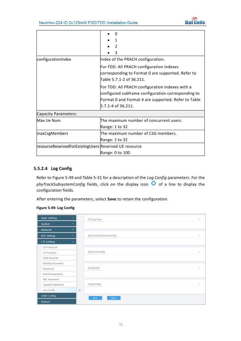
76
• 0 • 1 • 2 • 3
configurationIndex Index of the PRACH configuration.
For FDD: All PRACH configuration indexes corresponding to Format 0 are supported. Refer to Table 5.7.1-2 of 36.211.
For TDD: All PRACH configuration indexes with a configured subframe configuration corresponding to Format 0 and Format 4 are supported. Refer to Table 5.7.1-4 of 36.211.
Capacity Parameters: Max Ue Num The maximum number of concurrent users.
Range: 1 to 32 maxCsgMembers The maximum number of CSG members.
Range: 1 to 32 resourceReservedForExistingUsers Reserved UE resource
Range: 0 to 100
5.5.2.4 Log Config
Refer to Figure 5-49 and Table 5-31 for a description of the Log Config parameters. For the phyTrackSubsystemConfig fields, click on the display icon of a line to display the configuration fields.
After entering the parameters, select Save to retain the configuration.
Figure 5-49: Log Config

77
Table 5-31: Log Config
Parameter Name Description LTE log level (Figure 5-50): L2 log level L2 log level is not used in Release 2.x.x or later RRC log level RRC log level oamAdapter log level OAM adapter log level RRM log level RRM log level SON log level SON log level OAM log level OAM logs log level phyTraceSubsystemConfig (Figure 5-50): Subsystem Select the subsystem. streamToRemoteHost Indicates whether logs from this subsystem will be logged to
the remote host logToFile Indicates whether logs from this subsystem will be logged to
the local file forwardPort User Datagram Protocol (UDP) port number used for remote
logging separateLog Indicates whether to log this subsystem separately. Needed
only when logToFile is true. For LTE_L1 and LTE_L2 this must be true.
logFileSize The size of a single log file. No checking is done on whether the file system has enough free space to hold the logs.
logFileCount Number of logs, including the current one, to keep. Is used for rotation.
logFileComp Compression level for the log files. Recommend leaving the default value.
mmsgCount Number of messages to pull at a time using recvmmsg. Recommend leaving the default value.
phyTraceConfig (Figure 5-51): forwardIPAddr Set the IP address of the remote host. collectStats If set to false, stats of the log system will not be collected l1LogType Determines whether to log l1 to binary or just pcap or to
include all headers(pcap/eth/ip/udp). Only ALL_HEADERS is supported currently.
wiresharkEnabled Indicates whether or not wireshark capture is enabled for signaling(UU/S1AP/X2AP).
phyTraceNetworkCaptureConfig (Figure 5-52): Interface Name of the network interface PcapFilter Filter to apply while capturing Packet Capture (pcap) packets.
Any updates to the filter will take effect the next time the interface is enabled again. Example: sctp port 36412 or sctp port 36422 Range: 1 to 256 digits

78
Enable Switch of this configuration boardConf (Figure 5-53): boardConf Log level of the boardConf subsystem.
Options: CRIT ERROR WARNING NOTICE INFOR DEBUG DEVEL
Figure 5-50: LTE log level & phyTraceSubsystemConfig
Figure 5-51: phyTraceConfig

79
Figure 5-52: phyTraceNetworkCaptureConfig
Figure 5-53: boardConf
5.6 Reboot
To reboot the eNB, go to the Reboot menu in the eNB GUI and click on Reboot Now. The eNB will reboot immediately. It will take about 3 minutes for the eNB to complete the reboot.
Caution: Rebooting the eNB will disrupt service.

80
Appendix A: Technical Specifications
Hardware Specifications Item Description
LTE Mode FDD/TDD
Frequency Bands FDD: Bands 1/2/3/4/5/7 and customized TDD: Bands 40/41/42/43/48 and customized
Channel Bandwidth FDD Bands 1/2/3/4/7: 5/10/15/20 MHz FDD Band 5: 5/10 MHz TDD: 5/10/15/20 MHz
Max Output Power 21 dBm / antenna
Receive Sensitivity FDD: -102 dBm TDD Bands 40/41: -101 dBm TDD Bands 42/43/8: -100 dBm
Synchronization Mode GPS or network listening Backhaul Mode 1 RJ-45 Ethernet interface (1 GE) MIMO DL 2*2
Dimension (HxWxD) 6.9 x 5.1 x 1.2 inches 175 x 130 x 30 millimeters
Installation Method Desktop, ceiling, or wall mount Antenna 5 dBi omni-directional
Power Consumption FDD: < 15W TDD: < 12W
Power Supply 220V AC to 12V DC adaptor (multiple standards options) PoE+, IEEE 802.3at standard
Weight About 1.1 lbs (500 grams)
Note 1: Different models support different frequency bands.
Note 2: The test method of receiving sensitivity is proposed by the 3GPP TS 36.104, which is based on 5 MHz
bandwidth, FRC A1-3 in Annex A.1 (QPSK,R=1/3,25RB) standard.

81
Software Specifications Item Description
LTE Standard 3GPP Release 9
Peak Rate
20 MHz
FDD: DL 150 Mbps, UL 50 Mbps TDD: SA1: DL 80 Mbps, UL 20 Mbps SA2: DL 110 Mbps, UL 10 Mbps
10 MHz
FDD: DL 75 Mbps, UL 25 Mbps TDD: SA1: DL 40 Mbps, UL 7 Mbps SA2: DL 55 Mbps, UL 5 Mbps
User Capacity 48 (FDD) and 32 (TDD) concurrent users per cell QoS Control 3GPP Standard QCI
Modulation UL: QPSK, 16QAM DL: QPSK, 16QAM, 64QAM
Voice Solution CSFB, VoLTE, eSRVCC
Traffic Offload Local IP Access (LIPA) Selected IP Traffic Offload (SIPTO)
SON
Self-organizing network: • Automatic setup • Automatic Neighbor Relation (ANR) • PCI confliction detection
UL Interference Detection
Supported
RAN Sharing Supported Network Management Interface
TR069 interface protocol
Northbound Interface Web service, socket, FTP, and other interface modes MTBF ≥ 100000 hours MTTR ≤ 1 hour
Maintenance
Remote/local maintenance, based on SSH protocol Online status management Performance statistics Fault management Configuration management Local or remote software upgrade Logging Connectivity diagnosis Automatic start and configuration Alarm reporting KPI recording User information tracing

82
Environmental Specifications Item Description
Operating Temperature 32°F to 104°F / 0°C to 40°C Humidity 5% to 95%
Global Part Numbers Item Description
pBS4111 Band 42/43 indoor eNodeB

83
Appendix B: FAQs If you have questions, please check the list of frequently asked questions (FAQs) on the Baicells support website or the Facebook support forum.
• Baicells support website - https://na.Baicells.com/support/
• Baicells support forum on Facebook - https://www.facebook.com/groups/Baicellsoperatorsupportgroup/
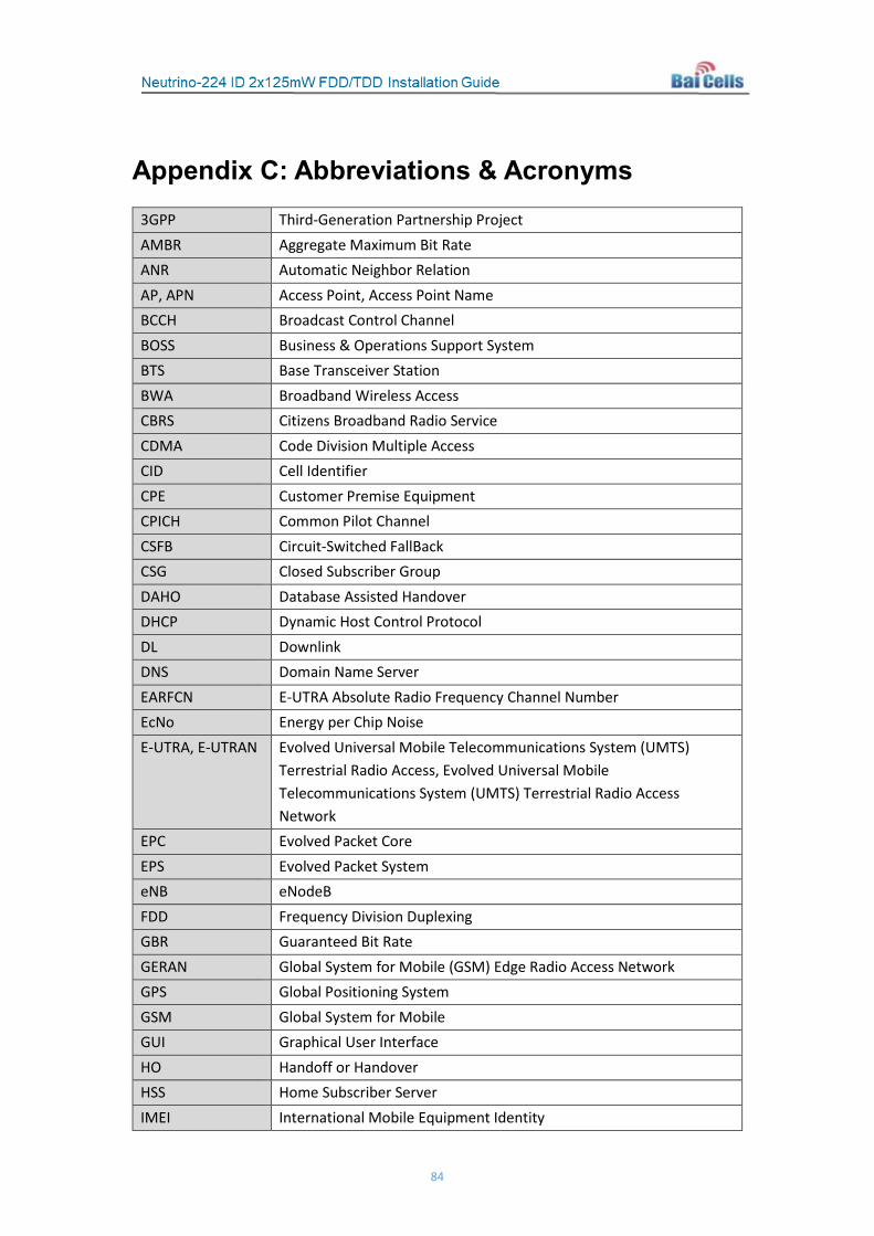
84
Appendix C: Abbreviations & Acronyms 3GPP Third-Generation Partnership Project AMBR Aggregate Maximum Bit Rate ANR Automatic Neighbor Relation AP, APN Access Point, Access Point Name BCCH Broadcast Control Channel BOSS Business & Operations Support System BTS Base Transceiver Station BWA Broadband Wireless Access CBRS Citizens Broadband Radio Service CDMA Code Division Multiple Access CID Cell Identifier CPE Customer Premise Equipment CPICH Common Pilot Channel CSFB Circuit-Switched FallBack CSG Closed Subscriber Group DAHO Database Assisted Handover DHCP Dynamic Host Control Protocol DL Downlink DNS Domain Name Server EARFCN E-UTRA Absolute Radio Frequency Channel Number EcNo Energy per Chip Noise E-UTRA, E-UTRAN Evolved Universal Mobile Telecommunications System (UMTS)
Terrestrial Radio Access, Evolved Universal Mobile Telecommunications System (UMTS) Terrestrial Radio Access Network
EPC Evolved Packet Core EPS Evolved Packet System eNB eNodeB FDD Frequency Division Duplexing GBR Guaranteed Bit Rate GERAN Global System for Mobile (GSM) Edge Radio Access Network GPS Global Positioning System GSM Global System for Mobile GUI Graphical User Interface HO Handoff or Handover HSS Home Subscriber Server IMEI International Mobile Equipment Identity
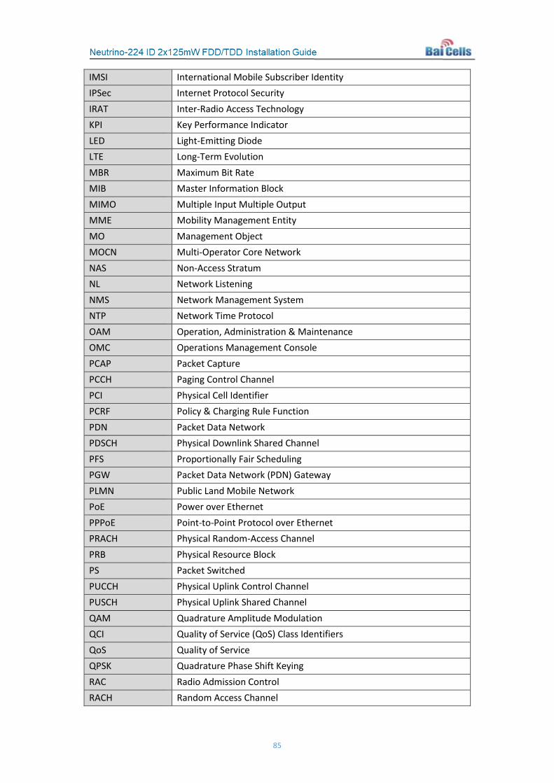
85
IMSI International Mobile Subscriber Identity IPSec Internet Protocol Security IRAT Inter-Radio Access Technology KPI Key Performance Indicator LED Light-Emitting Diode LTE Long-Term Evolution MBR Maximum Bit Rate MIB Master Information Block MIMO Multiple Input Multiple Output MME Mobility Management Entity MO Management Object MOCN Multi-Operator Core Network NAS Non-Access Stratum NL Network Listening NMS Network Management System NTP Network Time Protocol OAM Operation, Administration & Maintenance OMC Operations Management Console PCAP Packet Capture PCCH Paging Control Channel PCI Physical Cell Identifier PCRF Policy & Charging Rule Function PDN Packet Data Network PDSCH Physical Downlink Shared Channel PFS Proportionally Fair Scheduling PGW Packet Data Network (PDN) Gateway PLMN Public Land Mobile Network PoE Power over Ethernet PPPoE Point-to-Point Protocol over Ethernet PRACH Physical Random-Access Channel PRB Physical Resource Block PS Packet Switched PUCCH Physical Uplink Control Channel PUSCH Physical Uplink Shared Channel QAM Quadrature Amplitude Modulation QCI Quality of Service (QoS) Class Identifiers QoS Quality of Service QPSK Quadrature Phase Shift Keying RAC Radio Admission Control RACH Random Access Channel

86
RAN Radio Access Network RAT Radio Access Technology RLC Radio Link Control RR Round Robin RRC Radio Resource Control RRM Radio Resource Management RSCP Received Signal Code Power RSRP Reference Symbol Received Power RSRQ Reference Signal Received Quality RSSI Received Signal Strength Indicator SF Spreading Factor SFA SubFrame Assignment SFP Small Form-Factor Pluggable SGW Serving Gateway SIB System Information Block SIM Subscriber Identity Module SINR Signal-to-Interference-plus-Noise Ratio SNR Signal-to-Noise Ratio SON Self-Organizing Network SSP Special Subframe Pattern TAC Tracking Area Code TAI Tracking Area Identifier TDD Time Division Duplexing TDS Time Domain Scheduling TFCS Transport Format Combination Synchronization TPM Transmit Power Management TTI Transmission Time Interval UDP User Datagram Protocol UE User Equipment UL Uplink UMTS Universal Mobile Telecommunications System USIM Universal Subscriber Identity Module VoIP Voice over Internet Protocol VPLMN Visited Public Land Mobile Network VPN Virtual Private Network WCDMA Wideband Code Division Multiple Access WLAN Wireless Local Area Network


