Published in IET Generation, Transmission & Distribution Received on 27th February 2013 Revised on 24th April 2013 Accepted on 7th May 2013 doi: 10.1049/iet-gtd.2013.0135 ISSN 1751-8687 New algorithm for the protection of delta-hexagonal phase shifting transformer Umar Khan 1 , Tarlochan S. Sidhu 2 1 Department of Electrical and Computer Engineering, Western University, London, ON, Canada 2 Faculty of Engineering and Applied Science, University of Ontario Institute of Technology, Oshawa, ON, Canada E-mail: [email protected]Abstract: Delta/hexagonal phase shifting transformer (PST) represents both magnetically coupled and electrically connected circuits, which makes it unique in design and construction from a standard transformer. Conventionally, differential protection serves as a main protection element of PST and offers distinguished features such as speed and selectivity. On the contrary, it is prone to various new challenges in addition to well-recognised traditional ones when applied to delta/hexagonal PST. New challenges include non-standard phase shift between two ends, saturation of the series winding, dependence of differential/ restraining currents on tap changer position and turn–turn fault detection. This study exploits the unique design of PST and explores the suitability of applying electromagnetic equations by presenting a new algorithm for the protection of PST. In addition to the internal/external fault detection and discrimination capability, unlike differential protection, the proposed algorithm remains stable during magnetisation inrush current, current transformer saturation and saturation of the series winding. Even though the implementation of the proposed algorithm requires currents, voltages and tracking of the tap- changer position, capabilities of the algorithm make it a distinguished and unique protection solution. Performance of the algorithm is tested and analysed for various fault and non-faulted power system conditions using power systems computer aided design/electromagnetic transient including DC (PSCAD/EMTDC) software. 1 Introduction Phase shifting transformer (PST) presents an economical and reliable solution as compared to flexible alternating current transmission system devices, for example, dynamic-flow controller and unified/interline power-flow controller [1]. PST is applied based on the design type and construction. It can be constructed two-core or single-core symmetrical/ asymmetrical [2, 3]. Single-core symmetrical PSTs are of two kinds: standard-delta and delta-hexagonal. A symmetrical design alters the phase angle with equal magnitudes of source- and load-side voltages, whereas an asymmetrical design alters the phase shift and voltage magnitude, which can cause changes in the reactive power flow [3]. Using PST, power flow can be controlled by changing the phase shift angle δ between the PST source- and load-side voltages, V S and V L , respectively. Current differential protection has been widely used for the protection of standard and non-standard transformers [4]. It provides speed and selectivity and therefore responds to faults within the boundary of the protected zone in a very fast manner. On the contrary, it is also well-recognised that no-fault conditions like current transformer (ct) saturation; ct ratio mismatch, magnetising inrush currents and over-excitation jeopardise the security of the relay [5]. Therefore to provide a secure operation differential protection must be complemented with an indicator of the no-fault condition. Commonly used indicators are second and fifth harmonic contents in the inrush current and flux restrained differential protection [6, 7]. However, using the harmonic contents as an indicator in the modern transformer, which runs at higher flux density, can affect the security of the relay [8–10]. In addition to the aforementioned traditional problems associated with differential protection, PST brings new challenges to the differential protection. The new challenges influencing the sensitivity and stability of the PST differential protection are: non-standard phase shift between source and load sides, saturation of the series winding and turn-to-turn faults [11]. In practice, two standard differential elements are used for the protection of hexagonal PST [12]. Each element presents the differential current measuring principle that reflects the electrically connected zone of series- and exciting-winding. However, it is not able to provide the protection against any turn–turn fault in the winding. Few new techniques [13–15] based on standard percentage differential principle have been proposed which provide alternate solution of PST protection. Reference [14] proposes a phase/magnitude compensation algorithm to solve the dilemma of non-standard phase shift between two ends (source- and load-side) by tracking the tap position of the PST. The differential current measuring principle reflects the vector sum of the compensated currents without considering the circuit (magnetic or electrical) it represents. The advantage of the technique is that it can be applied to www.ietdl.org 178 IET Gener. Transm. Distrib., 2014, Vol. 8, Iss. 1, pp. 178–186 & The Institution of Engineering and Technology 2013 doi: 10.1049/iet-gtd.2013.0135
Transcript
www.ietdl.org
1&
Published in IET Generation, Transmission & DistributionReceived on 27th February 2013Revised on 24th April 2013Accepted on 7th May 2013doi: 10.1049/iet-gtd.2013.0135
78The Institution of Engineering and Technology 2013
ISSN 1751-8687
New algorithm for the protection of delta-hexagonalphase shifting transformerUmar Khan1, Tarlochan S. Sidhu2
1Department of Electrical and Computer Engineering, Western University, London, ON, Canada2Faculty of Engineering and Applied Science, University of Ontario Institute of Technology, Oshawa, ON, Canada
Abstract: Delta/hexagonal phase shifting transformer (PST) represents both magnetically coupled and electrically connectedcircuits, which makes it unique in design and construction from a standard transformer. Conventionally, differential protectionserves as a main protection element of PST and offers distinguished features such as speed and selectivity. On the contrary, itis prone to various new challenges in addition to well-recognised traditional ones when applied to delta/hexagonal PST. Newchallenges include non-standard phase shift between two ends, saturation of the series winding, dependence of differential/restraining currents on tap changer position and turn–turn fault detection. This study exploits the unique design of PST andexplores the suitability of applying electromagnetic equations by presenting a new algorithm for the protection of PST. Inaddition to the internal/external fault detection and discrimination capability, unlike differential protection, the proposedalgorithm remains stable during magnetisation inrush current, current transformer saturation and saturation of the serieswinding. Even though the implementation of the proposed algorithm requires currents, voltages and tracking of the tap-changer position, capabilities of the algorithm make it a distinguished and unique protection solution. Performance of thealgorithm is tested and analysed for various fault and non-faulted power system conditions using power systems computeraided design/electromagnetic transient including DC (PSCAD/EMTDC) software.
1 Introduction
Phase shifting transformer (PST) presents an economical andreliable solution as compared to flexible alternating currenttransmission system devices, for example, dynamic-flowcontroller and unified/interline power-flow controller [1].PST is applied based on the design type and construction. Itcan be constructed two-core or single-core symmetrical/asymmetrical [2, 3]. Single-core symmetrical PSTs are oftwo kinds: standard-delta and delta-hexagonal. Asymmetrical design alters the phase angle with equalmagnitudes of source- and load-side voltages, whereas anasymmetrical design alters the phase shift and voltagemagnitude, which can cause changes in the reactive powerflow [3]. Using PST, power flow can be controlled bychanging the phase shift angle δ between the PST source-and load-side voltages, VS and VL, respectively.Current differential protection has been widely used for the
protection of standard and non-standard transformers [4]. Itprovides speed and selectivity and therefore responds tofaults within the boundary of the protected zone in a veryfast manner. On the contrary, it is also well-recognised thatno-fault conditions like current transformer (ct) saturation;ct ratio mismatch, magnetising inrush currents andover-excitation jeopardise the security of the relay [5].Therefore to provide a secure operation differentialprotection must be complemented with an indicator of theno-fault condition. Commonly used indicators are second
and fifth harmonic contents in the inrush current and fluxrestrained differential protection [6, 7]. However, using theharmonic contents as an indicator in the moderntransformer, which runs at higher flux density, can affectthe security of the relay [8–10].In addition to the aforementioned traditional problems
associated with differential protection, PST brings newchallenges to the differential protection. The new challengesinfluencing the sensitivity and stability of the PSTdifferential protection are: non-standard phase shift betweensource and load sides, saturation of the series winding andturn-to-turn faults [11].In practice, two standard differential elements are used for
the protection of hexagonal PST [12]. Each element presentsthe differential current measuring principle that reflects theelectrically connected zone of series- and exciting-winding.However, it is not able to provide the protection against anyturn–turn fault in the winding.Few new techniques [13–15] based on standard percentage
differential principle have been proposed which providealternate solution of PST protection. Reference [14]proposes a phase/magnitude compensation algorithm tosolve the dilemma of non-standard phase shift between twoends (source- and load-side) by tracking the tap position ofthe PST. The differential current measuring principlereflects the vector sum of the compensated currents withoutconsidering the circuit (magnetic or electrical) it represents.The advantage of the technique is that it can be applied to
IET Gener. Transm. Distrib., 2014, Vol. 8, Iss. 1, pp. 178–186doi: 10.1049/iet-gtd.2013.0135
Fig. 1 Hexagonal PST
a Windings connections of hexagonal PSTb Phase A diagram of hexagonal PST running at maximum tap position D = 1c Phase A diagram of hexagonal PST running at some tap position D≠ 1
www.ietdl.org
any type of PST. However, it provides limited sensitivity toturn–turn faults. Moreover, in addition to tap positionreading, computation of the differential current also requiresbase currents of both ends at each tap position.Reference [15] proposes various methods based on the
differential current principles derived from the totalampere-turns of the magnetically coupled series- andexciting-winding. The proposed methods includecomputation of differential quantity with and withouttracking the tap position of the PST. The algorithmprovides more sensitivity to turn–turn faults as compared to[14]. However, dilemma of varying on-load phase shiftexists because of the dependency of restrain currentmagnitude on the PST loading or varying phase shift. Forexample differential characteristic set on mid-tap positioncan result the insensitivity to low current faults when thePST is running at higher tap positions and jeopardisesecurity on occurrence of even small false differentialcurrent when the PST is running at lower tap positions.All existing methods based on differential protection have
strong association with conventional and new challenges.These challenges influence the overall performance andproper operation of the differential protection applied toPST. Therefore significant scope of research work stillexists for the development of new protection techniques thatprovide a solution, which shows good level of immunity tofalse differential current conditions in addition to internal/external fault discrimination.Standard single- and three-phase transformers protection
methods based on electromagnetic equations are knownfrom [16–19]. In addition to the internal/external faultdiscrimination, the electromagnetic equation-basedtechnique resolves the problem of magnetisation inrushcurrent. Reference [16] uses the primary and secondarywindings electromagnetic equations of the standardtransformer (single- or three-phases) to develop theelectromagnetic differential equations (EDE). Duringnormal system conditions, the left- and right-side of EDEare equal but during internal fault conditions, the algorithmcomputes a significant error between left- and right-side.This paper presents two methods based on electromagnetic
equations and explores the suitability of applying thesetechniques for the protection of hexagonal PST. Likestandard transformer, the electromagnetic differentialprotection principle I (EDP-I) obtained by combining thePST series- and exciting-winding electromagnetic equationsis presented in Section 2.1. Section 2.2 shows, why thepresented method of Section 2.1 (EDP-I) is not sufficient toprovide a complete protection of PST by presenting variousproblems and limitations. To solve the dilemmas associatewith EDP-I, Section 2.3 presents electromagneticdifferential protection principle II (EDP-II) which exploitsthe unique design of PST by combining both magneticallyand electrically connected circuits to obtain the EDEs.Section 3 shows the performance analysis of the proposedtechnique followed by the discussions and conclusions inSection 4.
As shown in Fig. 1a, the tap winding with which the source (S)and load (L) are connected is called the series winding, whereasthe excitation winding is connected to the other two phases,
IET Gener. Transm. Distrib., 2014, Vol. 8, Iss. 1, pp. 178–186doi: 10.1049/iet-gtd.2013.0135
making delta connections. Hence, the quadrature voltage ΔVis developed; this, when added to the nominal voltage. Vn
will generate the phase shift between the source and the loadsides [3]. Let us assume that PST is running at full tapposition D (when load-side leads source-side, tap position Dvary between 0 and 1 whereas; when load-side lagssource-side tap position D vary between 0 and ‒1) andconsidering Fig. 1b, we can write electromagnetic equationsfor series- and exciting-windings as
VA = RAIA + jXAIA +MAaIa (1)
Va = MaAIA − RaIa − jXaIa (2)
where VA and Va are phase ‘A’ voltages at series- andexciting-winding terminals, respectively. IA and Ia are thecurrents in series- and exciting-winding of phase A,respectively. RA/XA and Ra /Xa are the resistance/reactanceof series- and exciting-winding, respectively. MAa and MaA
are the flux linkages contributed by series-to-excitingwinding and vice versa, respectively.
179& The Institution of Engineering and Technology 2013
www.ietdl.org
Ampere-turn relation of the magnetically coupled series-
and exciting-winding at some tap position D is written as
DNIA − Ia = 0 ⇒ IAIa
= 1
DN(3)
where N is the series- to exciting-winding turn ratio.It is known from [20] that series- and exciting-winding
are magnetically coupled on the same leg of thethree-legged core. Therefore for a linear transformermodel, it is justified to assume that MAa =MaA [21, 22].By combining and rearranging the magnetically coupledseries- and exciting-winding (1) and (2) and using (3), wecan obtain
VA = RAIA + jXAIA + DN Va + RaIa + jXaIa( )
(4)
Considering Fig. 1b, we can replace VA in (4) with thesource- and load-side voltages, VSA and VLA, respectively,by using the relation VA = VSA ‒ VLA, hence
VSA − VLA = IA RA + jXA
( )+ DNVa + DNIa Ra + jXa
( )(5)
Left-side of (5) is the measured value of VS ‒ VL, whereas;right-side is the estimated value of VS ‒ VL. By subtractingthe left- and right-hand side of (5), one can obtain theabsolute error |DIFF| as
DIFF| | = VSA − VLA
( )−∣∣ IA RA + jXA
( )(+ DNVa + DNIa Ra + jXa
( ))∣∣According to EDP, during normal system conditions (5)remains valid and relay computes small or zero (ideally)absolute error |DIFF|. However, in the event of internalfault conditions, electromagnetic differential relaycomputes significantly large error |DIFF| between themeasured and estimated value of the VS ‒ VL.Electromagnetic differential protection unit (EDU) willoperate if the error |DIFF| is larger than the pre-specifiedthreshold, THRES.In a similar manner, the EDEs for phase B and phase C can
also be derived.
2.2 Problems and limitations of EDP-I
† The principle presented in Section 2.1 works in a verygood agreement whereas the PST is running at maximumtap position. However, when the PST is at some tapposition 0≤D < 1, as shown in Fig. 1c, part of theseries-winding Wdg.A1 and Wdg.A2 remain unprotected.Therefore (5) is not sufficient to provide the completeprotection solution against the internal fault in thehexagonal PST.† The technique requires series- and exciting-windingsterminal voltages. Series-winding source- and load-sideterminal voltages are easily available at bus andtransmission levels. However, requirement of the additionalvoltage measurement at exciting-winding terminal wouldincrease the cost of overall protection.† The error |DIFF| computed by EDP-I in the event ofexternal fault with ct saturation or series-windingsaturation of the transformer is significantly large.Increasing the THRES setting solves the problem but
180& The Institution of Engineering and Technology 2013
results in less sensitivity to the low current faults andinter-turn faults.† Algorithm also requires winding parameters as a functionof tap position, which is seldom available by themanufacturer. Nameplate information is easily available,however; it only contains positive-sequence impedance atmaximum tap position.† Magnitude of |DIFF| depends on the transformer loadingdue to varying phase shift. Therefore setting of THREScannot be fixed to maintain both stability and sensitivity ofthe relay. However, change of threshold setting with respectto tap position or phase shift is not a practical solution atthis point.
These problems lead us to the solution by proposing themodified protection principle as done in the followingsection.
2.3 Electromagnetic differential protectionprinciple II (EDP-II)
Following currents, voltages and impedances notations areused in this section:
IET Gener. Transm. Distrib., 2014, Vol. 8, Iss. 1, pp. 178–186doi: 10.1049/iet-gtd.2013.0135
www.ietdl.org
Replacing Va in (5) with (9) and rearranging we can obtain(see (10))As shown in Fig. 1c, looking into PST from source side,distribution of the currents in the series winding is such that
IA = ISA + IcIB = ISB + IaIC = ISC + Ib
(11)
Replacing IA, IB and IC in (10) with set of (11)
VSA − VLA = Ia ZaDN + 2ZA1DN − ZA1− D
2
( )N
( )+ IcZA
− IbZA1− D
2
( )N − ISB + ISC
( )ZA
1− D
2
( )N
+ ISAZA + (VSB − VLC)D+ 1
2
( )N
− VLB − VSC
( ) 1− D
2
( )N (12)
Similarly, for the other two phases we can write
VSB − VLB = Ib ZaDN + 2ZA1DN − ZA1− D
2
( )N
( )+ IaZA
− IcZA1− D
2
( )N − ISA + ISC
( )ZA
1− D
2
( )N
+ ISBZA + (VSC − VLA)D+ 1
2
( )N
− VLC − VSA
( ) 1− D
2
( )N (13)
VSC − VLC = Ic ZaDN + 2ZA1DN − ZA1− D
2
( )N
( )+ IbZA
− IaZA1− D
2
( )N − ISA + ISB
( )ZA
1− D
2
( )N
+ ISCZA + (VSA − VLB)D+ 1
2
( )N
− VLA − VSB
( ) 1− D
2
( )N (14)
Using basic transformer circuit theory [21], it is justified toassume that Za = ZA/N
2 (Ω) and proportionate parts of serieswinding (Wdg.A1 and Wdg.A2) impedances with respect totap position D, we can write
Za =ZAN 2
(V) (15a)
VSA − VLA = Ia Za + 2ZA1( )
DN + VSB
(
− VLB − VSC
( ) 1− D
2
( )N
IET Gener. Transm. Distrib., 2014, Vol. 8, Iss. 1, pp. 178–186doi: 10.1049/iet-gtd.2013.0135
ZA1 = ZA1− D
2D
( )(V) (15b)
Replacing Za and ZA1 in (12)–(14) using (15) we can obtain
VSA − VLA = ZA
Ia1
ND+ 1− D
2
( )N
( )− Ib
1− D
2
( )N
+Ic − ISB + ISC( ) 1− D
2
( )N + ISA
⎡⎢⎢⎣
⎤⎥⎥⎦
+ VSB − VLC
( ) D+ 1
2
( )N
− VLB − VSC
( ) 1− D
2
( )(16)
Similarly, for the other two phases we can write
VSB − VLB
= ZA
Ib1
ND+ 1− D
2
( )N
( )− Ic
1− D
2
( )N
+Ia − ISA + ISC( ) 1− D
2
( )N + ISB
⎡⎢⎢⎣
⎤⎥⎥⎦
+ VSC − VLA
( ) D+ 1
2
( )N − VLC − VSA
( ) 1− D
2
( )
(17)
VSC − VLC
= ZA
Ic1
ND+ 1− D
2
( )N
( )− Ia
1− D
2
( )N
+Ib − ISB + ISA( ) 1− D
2
( )N + ISC
⎡⎢⎢⎣
⎤⎥⎥⎦
+ VSA − VLB
( ) D+ 1
2
( )N − VLA − VSB
( ) 1− D
2
( )
(18)
As shown in Fig. 1c, looking into PST from load side,distribution of the currents in the series winding is such that
IA = ILA + IbIB = ILB + IcIC = ILC + Ia
(19)
Replacing IA, IB and IC in (14) with set of (23) and replacing
− VLC
)1+ 1− D
2D
( )( )DN
− IB + IC( )
ZA1− D
2
( )N + IAZA
(10)
181& The Institution of Engineering and Technology 2013
www.ietdl.org
Za and ZA1 with (19) we can obtain
VSA − VLA
= ZA
IaD
N+ 1− D
2
( )N
( )− Ic
1− D
2
( )N
+Ib − ILB + ILC( ) 1− D
2
( )N + ILA
⎡⎢⎢⎣
⎤⎥⎥⎦
+ VSB − VLC
( ) 1+ D
2N
( )− VLB − VSC
( ) 1− D
2
( )N
(20)
Similarly, for the other two phases we can write
VSB − VLB
= ZA
Ib1
ND+ 1− D
2
( )N
( )− Ia
1− D
2
( )N
+Ic − ILA + ILC( ) 1− D
2
( )N + ILB
⎡⎢⎢⎣
⎤⎥⎥⎦
+ VSC − VLA
( ) D+ 1
2
( )N − VLC − VSA
( ) 1− D
2
( )
(21)
VSC − VLC
= ZA
Ic1
ND+ 1− D
2
( )N
( )− Ib
1− D
2
( )N
+Ia − ILB + ILA( ) 1− D
2
( )N + ILC
⎡⎢⎢⎣
⎤⎥⎥⎦
+ VSA − VLB
( ) D+ 1
2
( )N − VLA − VSB
( ) 1− D
2
( )
(22)
Implementation of the EDEs (16)–(18) and (20)–(22) requirescurrents (at source-, load-side and exciting-winding) andvoltages (source- and load-side) measurements. In practice,each end of the series- and exciting-winding (locations 3–6in Fig. 1a) is brought out of the tank so that the connectionbetween the exciting-winding and series-winding of theother two phases can be done externally [12]. Thereforemeasurement of source-side, load-side and exciting-windingcurrents can be obtained by locating the cts at location 1, 2and 3 in Fig. 1a. The algorithm does not requireexciting-winding voltage and only requires source- andload-side terminal voltages which are normally available atbus and transmission levels.The algorithm also requires winding impedance is ZA at
each tap position. Winding parameters at each tap positionare seldom available from the transformer manufacturer.However, one can easily acquire the PST nameplateinformation. In addition to PST ratings, positive-sequenceimpedance (Z1@D = 1) of the PST measured at maximum tapposition (D = 1) is also given in the nameplate. By usingpositive-sequence impedance (Z1@D = 1), one can easily findthe winding parameters as a function of tap position [23].Therefore the proposed algorithm requires only Z1@D = 1
and automatically calculates ZA as a function of tap
182& The Institution of Engineering and Technology 2013
position D by using the following equation
ZA(D) = 0.5D2 1+ N + N2( )Z1 (V) (23)
Moreover, magnitude of |DIFF| has dependence on thetap-changer position or phase shift between the two ends.To minimise this dependence, the computed error |DIFF| ismade adaptive to the tap changer position. This is done bysimply dividing the left- and right-sides of (16)–(18) and(20)–(22) with the base quantity |VnD(1− 1∠δ)|. The basequantity is the function of tap position D and requiresconstant values of nominal system voltage Vn andmaximum phase shift δ, which can be obtained from thePST nameplate information.
2.4 Fault detection algorithm
The left-hand sides of (16)–(18) are calculated using themeasured values of source- and load-side voltage. Theright-hand sides of (16)–(18) are the estimated value of theleft-hand side. During the normal system conditions,difference or error |DIFF| between actual (left side) andestimated values (right side) of the VS–VL in (16)–(18) isvery small. However, in the event of internal fault, |DIFF| issignificantly very large. The same is true for (20)–(22) setof EDEs.To make the relay sensitive to all kinds of faults, sensitivity
of the relay can be increased by combining the decision fromboth the relays. RELAYS and RELAYL computes thedifference |DIFFS| and |DIFFL|, respectively, between actual(left side) and estimated values (right side) of the VS–VL in(16)–(18) and (20)–(22), respectively. To ensure thesensitivity in the event of low internal fault currentconditions, the decisions from both the relays are combined.A decision from the relay is set to 1 if |DIFF| is equal orgreater than the set threshold limit THRES. Using an ORgate logic between the RELAYS and RELAYL a finaloutput is set to 1(trip) or 0 (no trip).
3 Testing of the proposed algorithm andresults
To test and verify the proposed algorithm, a 138 kV powersystem network with transmission line of 100 km ismodelled and simulated in EMTDC/PSCAD. Emtpmodel proposed by Kasztenny and Rosolowski [23] isused for the modelling of PST. Three single-phasefour-winding transformers are used to model the PST.Manufacturer rating of the delta-hexagonal PST nominalpower rating: Sn = 150 MVA; nominal voltage rating:Vn = 138 kV; maximum no-load phase shift: δ = ±32.59° in 32 steps.The proposed algorithm is based on the operating condition
of the transformer; therefore implementation of the algorithmis done in time-domain. Instantaneous values from currentand voltage transformers are available at time step of 208.3µs (sampling rate of 4800 Hz). Prior to discretisation of thecontinuous time signals, analogue current and voltagesignals are passed through low-pass anti-aliasing filter.Computation of the algorithm mainly requires thefundamental frequency components therefore; a fifth orderButterworth low-pass filter is used to remove the higherfrequency components. Moreover, input signals areprocessed through the derivative component to remove the
IET Gener. Transm. Distrib., 2014, Vol. 8, Iss. 1, pp. 178–186doi: 10.1049/iet-gtd.2013.0135
www.ietdl.org
dc components. Sampling of the signals is done with asampling frequency of 1200 Hz.
3.1 Simulation cases
A large number of tests are performed to analyse theperformance of EDP-II. For different load conditions,phase–ground (ph–g), phase-to-phase (ph–ph), doublephase-to-ground (ph–ph–g) and three phase (3ph) wereapplied at various internal and external locations. Turn–turn faults of various spans of shorted-turns were appliedon series- and exciting-winding. Each fault scenario istested for various tap positions. Furthermore, theproposed algorithm is also tested for conditions likemagnetising inrush, series-winding saturation because ofover-voltages, ct saturation and high resistance faults.The test results will show us that the proposed techniqueperforms well and remains stable by minimising theerror introduced by the ct saturation and PSTseries-winding saturation.
3.2 Magnetising inrush current
As shown in Fig. 2a, significant magnetisation inrush currentsare obtained when the unloaded PST is energised whereas thesource-side phase voltages pass the zero-crossing and entersinto positive half cycle.In the traditional differential protection relays during inrush
current phenomena relay computes the large differentialcurrent. If not blocked by using the additional blockingunit, the differential relay can mal-operate. As mentionedbefore, second harmonic contents are significant in theinrush current, therefore ratio of the second harmonic tofundamental frequency contents are used as an indicator ofthe magnetisation of the transformer [8, 9]. However,
Fig. 2 Magnetisation inrush current and computed RELAYS andRELAYLa Magnetising inrush currentb and c |DIFF| computed by RELAYS and RELAYL, respectivelyd TRIP signals
IET Gener. Transm. Distrib., 2014, Vol. 8, Iss. 1, pp. 178–186doi: 10.1049/iet-gtd.2013.0135
today’s power transformers are different in design andmaterial then before and therefore run at higher flux densityand hence generate low harmonics content during inrushcurrent [10].The proposed technique is immune to magnetisation inrush
current. As shown in Figs. 2b and c, RELAYS and RELAYL
computes |DIFFS| and |DIFFL|, which are less than theTHRES setting of 0.4.
3.3 Occurrence of internal fault during inrushcurrent in an unloaded transformer
In conventional differential protection, during magnetisationinrush current conditions the relay is blocked by means ofblocking unit. Therefore if internal fault occurs whereas thetransformer is energised, traditional differential protection isnot able to operate. Our proposed solution solves thisproblem. As shown in Fig. 3, the proposed solutioncomputes the large |DIFF| and operates for the internal faultduring the magnetising of the PST.
3.4 Saturation of series winding
The voltage rating of the series winding that connects thesource- and load-side terminal with the system is lower thanthe voltage rating of the connected system [12]. Externalfault can result in a significant increase in the terminalvoltage. Therefore in the traditional differential protection,saturation of the series winding because of over-excitationcan result in the mal-operation of the relay. Differentialprotection is usually complemented with the restrainingunit. Ratio of fifth harmonic to fundamental frequencycontents in the inrush current is used as an indicator ofsaturation of the transformer. As mentioned before, inmodern transformers using the harmonic as an indicator offalse differential current can affect the security of thedifferential relay.To test the proposed technique in the event of PST
saturation, series winding is forced to saturate by increasing
Fig. 3 Internal fault during the magnetising of the PST
a and b |DIFF| signals computed by RELAYS and RELAYL, respectivelyc TRIP signals
183& The Institution of Engineering and Technology 2013
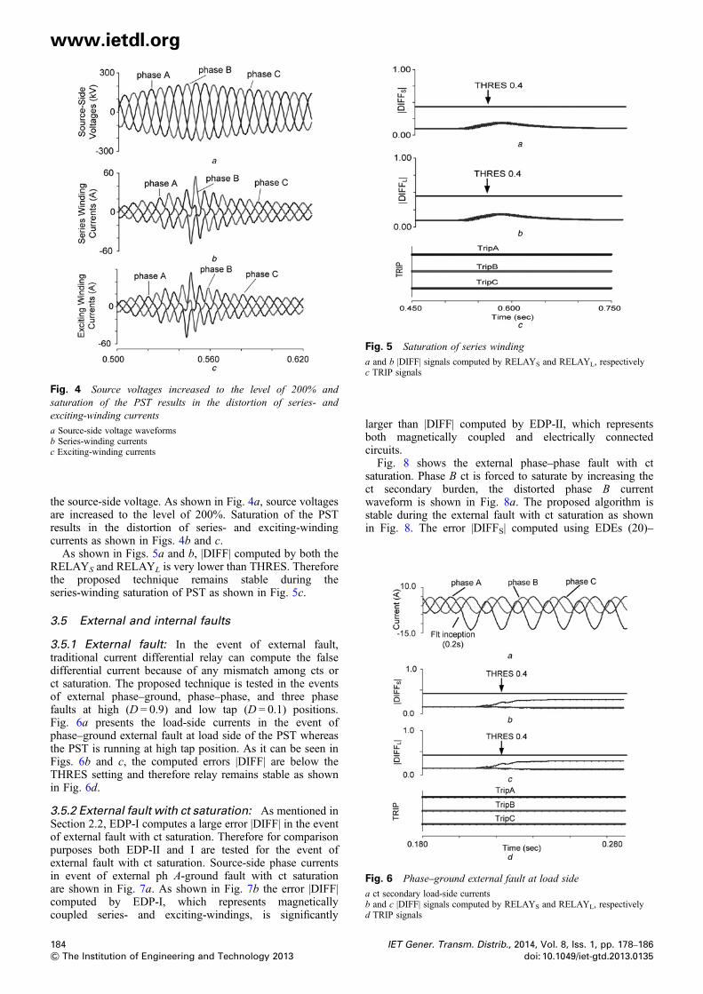
Fig. 5 Saturation of series winding
a and b |DIFF| signals computed by RELAYS and RELAYL, respectivelyc TRIP signals
Fig. 4 Source voltages increased to the level of 200% andsaturation of the PST results in the distortion of series- andexciting-winding currents
a Source-side voltage waveformsb Series-winding currentsc Exciting-winding currents
Fig. 6 Phase–ground external fault at load side
a ct secondary load-side currentsb and c |DIFF| signals computed by RELAYS and RELAYL, respectivelyd TRIP signals
www.ietdl.org
the source-side voltage. As shown in Fig. 4a, source voltagesare increased to the level of 200%. Saturation of the PSTresults in the distortion of series- and exciting-windingcurrents as shown in Figs. 4b and c.As shown in Figs. 5a and b, |DIFF| computed by both the
RELAYS and RELAYL is very lower than THRES. Thereforethe proposed technique remains stable during theseries-winding saturation of PST as shown in Fig. 5c.
3.5 External and internal faults
3.5.1 External fault: In the event of external fault,traditional current differential relay can compute the falsedifferential current because of any mismatch among cts orct saturation. The proposed technique is tested in the eventsof external phase–ground, phase–phase, and three phasefaults at high (D = 0.9) and low tap (D = 0.1) positions.Fig. 6a presents the load-side currents in the event ofphase–ground external fault at load side of the PST whereasthe PST is running at high tap position. As it can be seen inFigs. 6b and c, the computed errors |DIFF| are below theTHRES setting and therefore relay remains stable as shownin Fig. 6d.
3.5.2 External fault with ct saturation: As mentioned inSection 2.2, EDP-I computes a large error |DIFF| in the eventof external fault with ct saturation. Therefore for comparisonpurposes both EDP-II and I are tested for the event ofexternal fault with ct saturation. Source-side phase currentsin event of external ph A-ground fault with ct saturationare shown in Fig. 7a. As shown in Fig. 7b the error |DIFF|computed by EDP-I, which represents magneticallycoupled series- and exciting-windings, is significantly
184& The Institution of Engineering and Technology 2013
larger than |DIFF| computed by EDP-II, which representsboth magnetically coupled and electrically connectedcircuits.Fig. 8 shows the external phase–phase fault with ct
saturation. Phase B ct is forced to saturate by increasing thect secondary burden, the distorted phase B currentwaveform is shown in Fig. 8a. The proposed algorithm isstable during the external fault with ct saturation as shownin Fig. 8. The error |DIFFS| computed using EDEs (20)–
IET Gener. Transm. Distrib., 2014, Vol. 8, Iss. 1, pp. 178–186doi: 10.1049/iet-gtd.2013.0135
Fig. 7 Source-side phase currents and error |DIFF| computed byEDP-II and I
a Source-side secondary currentsb Error |DIFF| computed by EDP-II and I
Fig. 9 Turn–turn fault in exciting winding
a and b |DIFF| signals computed by RELAYS and RELAYL, respectivelyc TRIP signals
www.ietdl.org
(22) is very small and below THRES. Therefore as shown inFig. 8d, relay remains stable during external fault with severect saturation.
3.5.3 Internal fault: turn–turn: In traditional differentialprotection, the measuring principle of the differentialcurrent is based on ampere-turn balance between themagnetically coupled windings. Any unbalance because offault is monitored by the differential protection as adifferential current. Differential current produced because ofunbalance in the ampere-turn coupling of the windingsdepends on the level of fault current. The level of faultcurrent depends on the fault resistance, number of shortedturns and so on [24]. Depending on the number of shorted
Fig. 8 External phase–phase fault with ct saturation
a ct secondary load-side currentsb and c |DIFF| signals computed by RELAYS and RELAYL, respectivelyd TRIP signals
IET Gener. Transm. Distrib., 2014, Vol. 8, Iss. 1, pp. 178–186doi: 10.1049/iet-gtd.2013.0135
turns, the fault current is very high however; the differentialcurrent is relatively very small [25]. Therefore the currentdifferential protection has limited sensitivity to turn–turnfaults. Negatives-sequence differential protection is theother solution to detect the turn–turn fault. However, it isalso insensitive in the event of low current turn–turn faults[26]. Other method commonly used is the sudden-pressureor gas-type relays [25].The performance of the proposed technique is tested for
turn–turn faults of various shorted turns spans and PSTwith high and low taps positions. Fig. 9, illustrates a case ofinternal turn–turn fault of 1.5% of the winding shortedturns with PST running at tap position D = 0.1.
3.5.4 Internal fault: high resistive fault: As mentionedbefore that the sensitivity of the conventional differential
Fig. 10 Phase A to ground high resistive internal fault
a and b |DIFF| signals computed by RELAYS and RELAYL, respectivelyc TRIP signals
185& The Institution of Engineering and Technology 2013
www.ietdl.org
protection depends on the fault current level whereasmaintaining the security in the event of false differentialcurrent. In conventional differential relay, varying on-loadphase shift jeopardise the sensitivity in the event of lowfault current when the PST is running at maximum tapposition, whereas stability is compromised in the event offalse differential current when the PST is running at low tappositions.Fig. 10 presents the performance of the proposed method
for an internal phase–ground fault with high fault resistance(100 Ω) whereas the PST is running at tap position of 0.5 pu.
4 Discussions and conclusions
This paper presents a new approach for the protection of delta/hexagonal PST. The approach is based on the EDP thatrepresents not only the magnetically coupled phasewindings but also the electrically connected windings of thePST. The method is tested for various faulted andno-faulted power system conditions.Based on the performance analysis, capabilities and
limitations of the proposed algorithm in comparison to thedifferential protection-based techniques [11–15] are asfollows:
† Without any restraining or blocking unit, the proposedalgorithm remains stable during the magnetisation inrushcurrent. On the other hand, conventional differential isdependent on the harmonic-based blocking unit. However,modern transformers run at higher flux density and generatelow harmonics content during inrush current hence relaysecurity can be jeopardised [8–10].† The purposed algorithm performs well in the event ofsimultaneous internal fault and magnetisation inrushcurrent. However, conventional differential relay is not ableto operate in such kind of scenario because of trip block bythe blocking unit.† During series-winding saturation, the proposed algorithmremains stable whereas the conventional differentialprotection measures high differential current.† The proposed algorithm measures error |DIFF| belowthreshold during external fault with ct saturation. Standardcurrent differential relay measures large differential current,which can result in the mal-operation of the relay.† Unlike conventional differential protection characteristic,the non-standard varying phase shift does not impact thesensitivity of the relay in the event of low fault currentwhen the PST is running at high tap position and securityin the event of any false current when the PST is running atlow tap position.† The proposed algorithm provides good sensitivity againstlow turn–turn faults. The test shows us that relay performswell even when the shorted turns are 1.5% of the windingwhereas the PST is running at low tap position. However,as mentioned in the previous section that in the event ofturn–turn fault conventional differential protection has finitesensitivity and does not work for the low fault current.† Unlike conventional differential protection, the proposedalgorithm is sensitive to the high resistive faults andmeasures significant level of error |DIFF|.† The proposed algorithm requires three currents and twovoltages per phase. However, current differential protectionrequires currents to compute differential currents.† Like existing alternate current differential methods [13–15], the proposed algorithm also requires reading of the tap
186& The Institution of Engineering and Technology 2013
position from the PST. However, conventional differentialprotection [12] does not require any external readingsexcept current measurements.
5 References
1 Zhang, X.P., Rehtanz, C., Pal, B.: ‘Flexible AC transmission system:modeling and control’ (Springer, Germany, 2006, pp. 1–5
2 IEEE Std C57.135: ‘IEEE guide for the application, specification andtesting of phase shifting transformers, 2001’
3 Verboomen, J., Hertem, D.V., Schavemaker, P.H., Kling, W.L.,Belmans, R.: ‘Phase shifting transformer: Principles and applications’.Proc. Int. Conf. Future Power Systems., Amsterdam, Netherland,November 2005, p. 6
4 IEEE Std C37.91: ‘IEEE guide for protecting power transformers’, 20085 Phadke, A.G., Thorp, J.S.: ‘Computer relaying for power system’ (John
Wiley and Sons, Ltd, England, 2009, 2nd edn.)6 Kennedy, L.F., Haywards, C.D.: ‘Harmonic-current restrained relays for
differential protection’, AIEE Trans., 1938, 57, (5), pp. 262–2667 Phadke, A.G., Thorp, J.S.: ‘A new computer-based flux restrained
current-differential relay for power transformer protection’, IEEETrans. Power Appar. Syst., 1983, PAS-102, (11), pp. 3624–3629
8 Mekic, F., Girgis, R., Gajic, Z., Nyenhuis, Ed.: ‘Power transformercharacteristics and their effect on protective relays’. Proc. 33rd Conf.Western Protective Relay, College Station, TX, 17–19 October 2006,p. 10
9 Kulidjian, A., Kasztenny, B., Campbell, B.: ‘New magnetizing inrushrestraining algorithm for power transformer protection’. Proc. SeventhInt. Conf. Developments in Power Systems Protection, Amsterdam,Netherland, 2001, p. 4
10 Youssef, O.A.S.: ‘Wavelet-based technique for discrimination betweenfaults and magnetizing inrush currents in Transformers’, IEEE Trans.Power Deliv., 2003, 18, (1), pp. 170–176
11 Thompson, J., Miller, H., Burger, J.: ‘AEP experience with protection ofthree delta/hex phase angle regulating transformers’. Proc. AdvancedMetering, Protection, Control, Communication, and DistributedResources, College Station, TX, 2007, pp. 96–105
12 IEEE Power System Relaying Committee: Working Group K1,‘Protection of Phase Angle Regulating Transformers’ 1999
13 Hayder, T., Schaerli, U., Feser, K., Schiel, L.: ‘Universal adaptivedifferential protection for regulating transformers’, IEEE Trans. PowerDeliv., 2008, 23, (2), pp. 568–575
14 Gajic, Z.: ‘Use of standard 87T differential protection for specialthree-phase power transformers-part 1: theory’, IEEE Trans. PowerDeliv., 2012, 27, (3), pp. 1035–1040
15 Kasztenny, B., Rosolowski, E.: ‘Modeling and protection of hexagonalphase-shifting transformers—part II: protection’, IEEE Trans. PowerDeliv., 2008, 23, (3), pp. 1351–1358
16 Sachdev, M.S., Sidhu, T.S., Wood, H.C.: ‘A digital relaying algorithmfor detecting transformer winding faults’, IEEE Trans. Power Deliv.,1989, 4, (3), pp. 1638–1648
17 Phadke, A.C.,, Thorp, J.S.: ‘A new computer-based flux-restrainedcurrent-differential relay for power transformer protection’, IEEETrans. Power Appar. Syst., 1983, PAS-102, (11), pp. 3624–3628
18 Inagaki, K., Higaki, M., Matusi, Y., et al.: ‘Digital protection method forpower transformers based on an equivalent circuit composed of inverseinductance’, IEEE Trans. Power Deliv., 1988, 3, (4), pp. 1501–1510
19 Kang, YC., Lee, B.E., Kang, S.H., Crossley, P.A.: ‘Transformerprotection based on the increment of flux linkages’, IEE Proc.- Gener.Transm. Distrib., 2004, 151, (4), pp. 548–554
20 Garin, A.N.: United States Patent office 2292829, 194021 Vecchio, R.M.D., Poulin, B., Feghali, P.T., Shah, D.M., Ahuja, R.:
‘Transformer design principles: with applications to core-form powertransformers’ (CRC Press, New York, 2002, 2nd edn.), pp. 66–80
22 Central Station Engineers of Westinghouse Electric Corporation.‘Electrical transmission and distribution reference book’(Westinghouse Electric Corporation, Pennsylvania, USA, 1950),pp. 96–98
23 Kasztenny, B., Rosolowski, E.: ‘Modeling and protection of hexagonalphase-shifting transformers – part I: short-circuit model’, IEEE Trans.Power Deliv., 2008, 23, (3), pp. 1343–1350
24 Kasztenny, B., Thompson, M., Fischer, N.: ‘Fundamentals ofshort-circuit protection for transformers’. Proc. 63rd Annual Conf.Protective Relay Engineers, College Station, TX, 29 March–1 April2010, pp. 1–13
25 Protective relaying application guide. Alstom, pp. 256–25726 Blackburn, J.L., Domin, T.J.: ‘Protective relaying principles and
applications’ (CRC Press, Boca Raton, 2006¸ 3rd edn.), pp. 345–376
IET Gener. Transm. Distrib., 2014, Vol. 8, Iss. 1, pp. 178–186doi: 10.1049/iet-gtd.2013.0135