TRANSPORTATION RESEARCH RECORD 1150 11 New Austrian Tunneling Method Used for Design of Soft-Ground Tunnels for Washington Metro ROBERT J. JENNY, PRAKASH M. DONDE, AND HARALD WAGNER The design of Section E-5 tunnels of 01e Washington Metro u lng the New Austrian Tunneling Method (NATM) Is de- scribed. The twin-bore tunnel section, approximately 1,000 ft long, runs directly beneath Fort Totten Park Lo Washington, D.C., west of tbe District's border with Prince George's County, Maryland. In addition to a conventional tunnel design, Metro engineers d.lrected an alternate design using NATM. Although this type of design Is used extensively In Europe, tllls will be one of the first NATM applications to soft-ground tunnels in the United States. The NATM Is a method whereby the rock or soil formations surrounding a tunnel are integrated into an overall ringlike support structure; thus the formations become part of the support syst.em. The two main support elements are a reinforced shotcrete Initial lining and an unrein- forced final concrete lining. The tunnels will pass entirely through a cretaceous formation of stiff, silty clays and clayey sands. NATM appears to be a suitable metliod of constructing these tunnels because the soils apparently possess good stand- up time, the groundwater table Is low, and the tunnels are relatively short. Even though these tunnels have not yet been constructed, It Is beUeved tJ1at the design concepts presented will be useful to tunnel designers. Application of the New Austrian Tunneling Method (NATM) to the Section E-5 tunnels of the Washington, D.C., Metro is described. Washington Metro Section E-5 tunnels and Fort Totten Sta- tion are on the Greenbelt Route beneath Fort Totten Park in the vicinity of Fort Totten Drive, at the northeast border between Maryland and the District of Columbia (Figure 1). The twin- bore tunnel section is approximately 1,000 ft long with a ventilation shaft at the western end and a fan shaft at the eastern end (Figure 2). Approximately 300 ft of the station are to be constructed underground and the remaining 300 ft will be in open air. The tunnels will pass entirely through cretaceous formations of stiff, silty clays and clayey sands. Groundwater is at about the invert of the tunnels. Ground cover will range from 100 ft at the western end to 65 ft at the eastern end. The underground portion of the station is also being designed using NATM techniques. However, this paper deals only with the bored tunnels. This design will be one of the first NATM applications to soft-ground tunnels in the United States. Alter- native NATM contract documents will be prepared for compet- itive bidding against conventionally driven tunnel-boring R. J. Jenny and P. M. Donde, Jenny Engineering Corporation, 2 Edi- son Place, Springfield, N.J. 07081. H. Wagner, Mayreder Consult Engineering and Consulting Ltd., Sophiengutstrasse 20, A-4021 Linz, Austria. machine (TBM) or shield tunnels. The NATM design will incorporate techniques currently being used on the Vienna subway and those that have been used on the Munich subway. Even though the tunnels have not yet been constructed, it is believed that the design concepts presented here will be of interest to tunnel designers. FIGURE 1 Location of tunnels. ti w ... 240 ! 200 z 0 160 > w .... w 120 320+00 325+00 33c>+OO 335+00 FIGURE 2 Generalized geologic profile. NATM Design Principles Excavation of tunnels causes the in situ balance of stresses in the rock or soil mass to be changed by deformations related to the tendency of the mass to relax and converge until a new, stable state of equilibrium is reached. This equilibrium is achieved through a succession of stress redistribution processes.
Transcript
TRANSPORTATION RESEARCH RECORD 1150 11
New Austrian Tunneling Method Used for Design of Soft-Ground Tunnels for Washington Metro
ROBERT J. JENNY, PRAKASH M. DONDE, AND HARALD WAGNER
The design of Section E-5 tunnels of 01e Washington Metro u lng the New Austrian Tunneling Method (NATM) Is described. The twin-bore tunnel section, approximately 1,000 ft long, runs directly beneath Fort Totten Park Lo Washington, D.C., west of tbe District's border with Prince George's County, Maryland. In addition to a conventional tunnel design, Metro engineers d.lrected an alternate design using NATM. Although this type of design Is used extensively In Europe, tllls will be one of the first NATM applications to soft-ground tunnels in the United States. The NATM Is a method whereby the rock or soil formations surrounding a tunnel are integrated into an overall ringlike support structure; thus the formations become part of the support syst.em. The two main support elements are a reinforced shotcrete Initial lining and an unreinforced final concrete lining. The tunnels will pass entirely through a cretaceous formation of stiff, silty clays and clayey sands. NATM appears to be a suitable metliod of constructing these tunnels because the soils apparently possess good standup time, the groundwater table Is low, and the tunnels are relatively short. Even though these tunnels have not yet been constructed, It Is beUeved tJ1at the design concepts presented will be useful to tunnel designers.
Application of the New Austrian Tunneling Method (NATM) to the Section E-5 tunnels of the Washington, D.C., Metro is described.
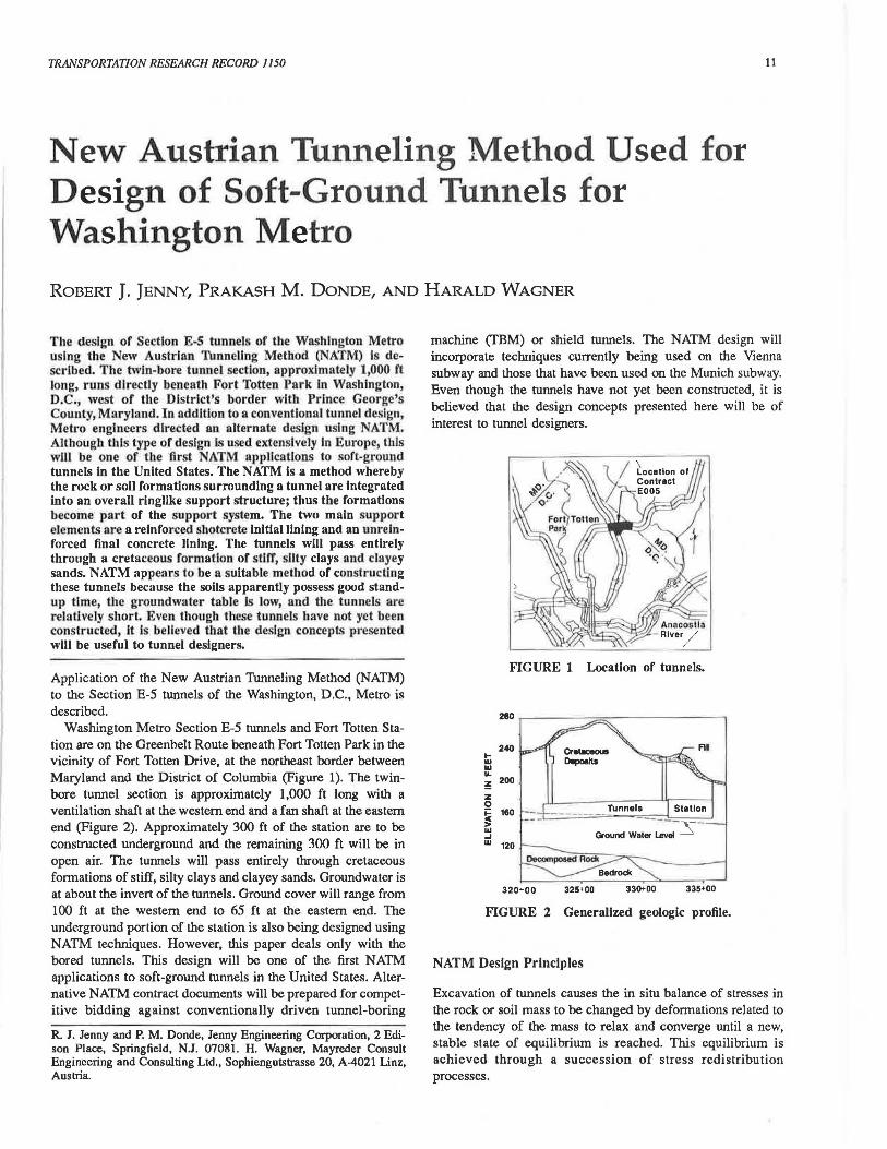
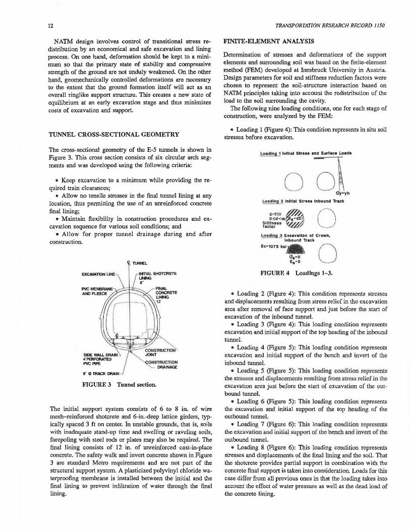
Washington Metro Section E-5 tunnels and Fort Totten Station are on the Greenbelt Route beneath Fort Totten Park in the vicinity of Fort Totten Drive, at the northeast border between Maryland and the District of Columbia (Figure 1). The twinbore tunnel section is approximately 1,000 ft long with a ventilation shaft at the western end and a fan shaft at the eastern end (Figure 2). Approximately 300 ft of the station are to be constructed underground and the remaining 300 ft will be in open air. The tunnels will pass entirely through cretaceous formations of stiff, silty clays and clayey sands. Groundwater is at about the invert of the tunnels. Ground cover will range from 100 ft at the western end to 65 ft at the eastern end. The underground portion of the station is also being designed using NATM techniques. However, this paper deals only with the bored tunnels. This design will be one of the first NATM applications to soft-ground tunnels in the United States. Alternative NATM contract documents will be prepared for competitive bidding against conventionally driven tunnel-boring
R. J. Jenny and P. M. Donde, Jenny Engineering Corporation, 2 Edison Place, Springfield, N.J. 07081. H. Wagner, Mayreder Consult Engineering and Consulting Ltd., Sophiengutstrasse 20, A-4021 Linz, Austria.
machine (TBM) or shield tunnels. The NATM design will incorporate techniques currently being used on the Vienna subway and those that have been used on the Munich subway. Even though the tunnels have not yet been constructed, it is believed that the design concepts presented here will be of interest to tunnel designers.
FIGURE 1 Location of tunnels.
ti w ...
240
! 200
z 0 ~ 160 > w .... w 120
320+00 325+00 33c>+OO 335+00
FIGURE 2 Generalized geologic profile.
NATM Design Principles
Excavation of tunnels causes the in situ balance of stresses in the rock or soil mass to be changed by deformations related to the tendency of the mass to relax and converge until a new, stable state of equilibrium is reached. This equilibrium is achieved through a succession of stress redistribution processes.
12
NATM design involves control of transitional stress redistribution by an economical and safe excavation and lining process. On one hand, deformation should be kept to a minimwn so that the primary state of stability and compressive strength of the ground are not unduly weakened On the other hand, geomechanically controlled deformations are necessary to the extent that the ground formation itself will act as an overall ringlike support structure. This creates a new state of equilibrium at an early excavation stage and thus minimizes costs of excavation and support.
TUNNEL CROSS-SECTIONAL GEOMETRY
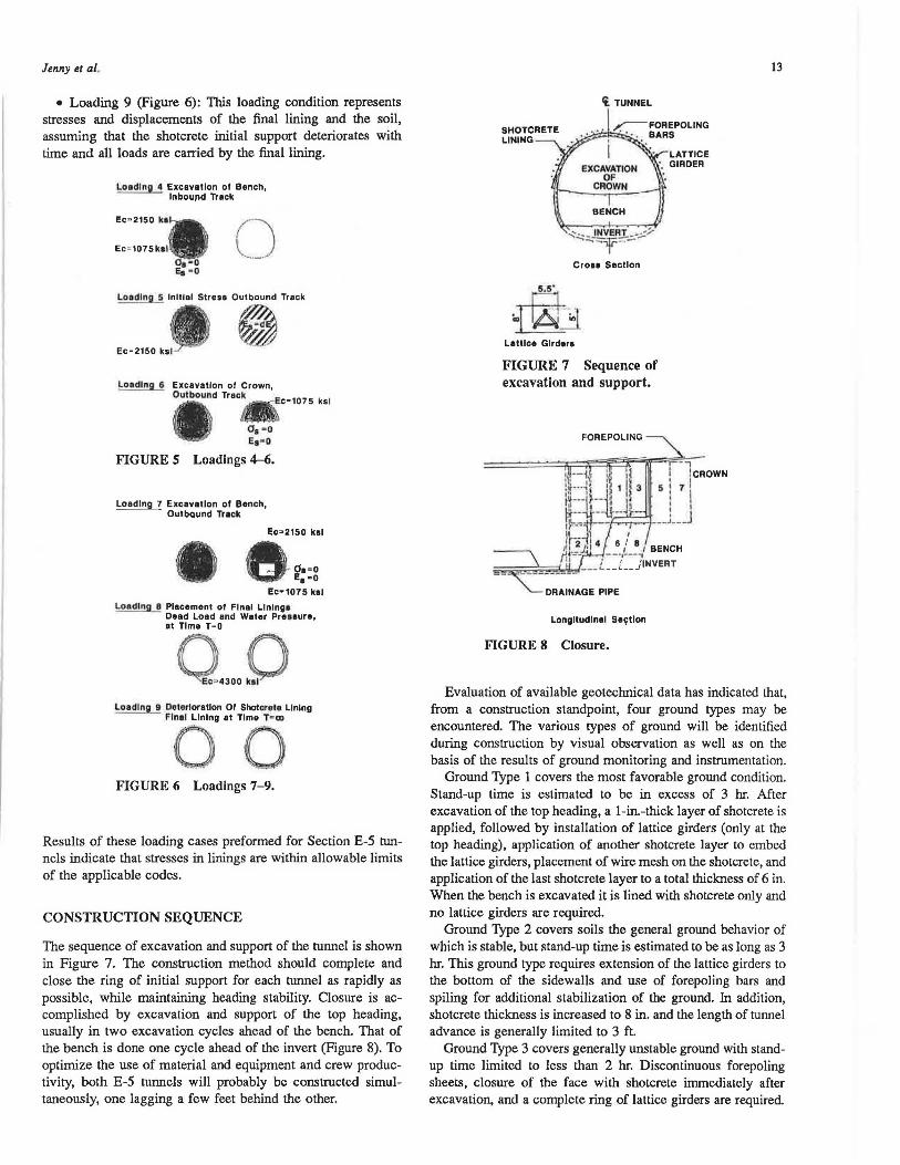
The cross-sectional geometry of the E-5 tunnels is shown in Figure 3. This cross section consists of six circular arch segments and was developed using the following criteria:
• Keep excavation to a minimwn while providing the required train clearances;
• Allow no tensile stresses in the final tunnel lining at any location. thus permitting the use of an unreinforced concrete final lining;
• Maintain flexibility in construction procedures and excavation sequence for various soil conditions; and
• Allow for proper tunnel drainage during and after construction.
~ TUNNEL
ONSTRUCT10N DRAINAGE
FIGURE 3 Tunnel section.
The initial support system consists of 6 to 8 in. of wire mesh- reinforced shotcrete and 6-in.-deep lattice girders, typically spaced 3 ft on center. In unstable grounds, lhal is, soils with inadequate stand-up time and swelling or raveling soils, forepoling with steel rods or plates may also be required. The final lining consists of 12 in. of unreinforced cast-in-place concrete. The safety walk and invert concrete shown in Figure 3 are standard Metro requirements and a.re nol pan of the structural support system. A plasticized polyvinyl chloride waterproofing membrane is installed between the initial and the final lining to prevent infiltration of water through the final lining.
TRANSPORTATION RESEARCH RECORD 1150
FINITE-ELEMENT ANALYSIS
Determination of stresses and deformations of the support elements and surrounding soil was based on the finite-element method (FEM) developed at Innsbruck University in Austria. Design parameters for soil and stiffness reduction factors were chosen to represent the soil-structure interaction based on NATM principles taking into account the redistribution of the load to the soil surrounding the cavity.
The following nine loading conditions, one for each stage of construction, were analyzed by the FEM:
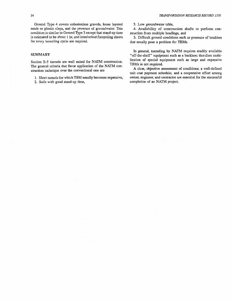
• Loading 1(Figure4): This condition represents in situ soil stresses before excavation.
~·~ .. ·~r Oy•yh
Loadln 2 Initial Stress Inbound Track
11• 111) ~~~· OSd<CD s• dE Stlflneaa lf//J factor "-L/L/'
Loading 3 Excavation of Crown, Inbound Track
Ec•1075 k•I• 0 01• 0 Ea· O
FIGURE 4 Loadings 1-3.
• Loading 2 (Figure 4): This condition represents stresses and displacements resulting from stress relief in the excavation area after removal of face support and just before the start of excavation of the inbound tunnel.
• Loading 3 (Figure 4): This loading condition represents excavation and initial support of the top heading of the inbound tunnel.
• Loading 4 (Figure 5): Thls loading condition represents excavation and initial support of the bench and invert of the inbound tunnel.
• Loading 5 (Figure S): This loading condition represents the stresses and displacements resulting from stress relief in the excavation area just before the start of excavation of the outbound tunnel.
• Loading 6 (Figure 5): This loading condition represents the excavation and initial support of the top heading of the outbound tunnel.
• Loading 7 (Figure 6): This loading condition represents the excavation and initial support of Lhe bench and invert of the outbound tunnel.
• Loading 8 (Figure 6): This loading condition represents stresses and displacements of the final lining and the soil. That the shotcrete provides partial support in combination with the concrete final support is taken into consideration. Loads for this case differ from all previous ones in that the loading takes into account the effect of water pressure as well as the dead ioad of the concrete lining.
Jenny et al.
• Loading 9 (Figure 6): This loading condition represents stresses and displacements of the final lining and the soil, assuming that the shotcrete initial support deteriorates with time and all loads are carried by the final lining.
Loading 4 Excavation ol Bench, lnbou11d Track
CJ Loading 5 lnltlal Stress Outbound Track
~~ Ec=2150 ksl
Loadln 6 Excavation ol Crown, Outbound Track E _
107 k - c- 5 sl
08 - 0 Es - O
FIGURE 5 Loadings 4-6.
Loading 7 Excavation ol Bench, --- Outbound Track
Ec~21so kal
e~==g Ec-1075 kal
Loadln 8 Placement of Final Lining• Dead Loed and Water PreHure, at Time T=O
Q.,.J) Loadln 9 Deterioration 01 Shotcrete Lining
- Final Lining at Time Tam
00 FIGURE 6 Loadings 7-9.
Results of these loading cases preformed for Section E-5 tun
nels indicate that stresses in linings are within allowable limits of the applicable codes.
CONSTRUCTION SEQUENCE
The sequence of excavation and support of the tunnel is shown in Figure 7. The construction method should complete and close the ring of initial support for each tunnel as rapidly as possible, while maintaining heading stability. Closure is accomplished by excavation and support of the top heading, usually in two excavation cycles ahead of the bench. That of the bench is done one cycle ahead of the invert (Figure 8). To optimize the use of material and equipment and crew productivity, both E-5 tunnels will probably be constructed simultaneously, one lagging a few feet behind the other.
Ii. TUNNEL
BENCH
'°"· INVERT __ ._:/ --, ---:;r,:: - - --- lr-
CroH Section
Lattice Glrdere
FIGURE 7 Sequence of excavation and support.
FORE POLING
LATTICE ·• GIRDER
r- icROWN
s I 71 I I
,:!J--;h--,..,.........-1--L J
Longitudinal Se~tlon
FIGURE 8 Closure.
13
Evaluation of available geotechnical data has indicated that, from a construction standpoint, four ground types may be encountered. The various types of ground will be identified during construction by visual observation as well as on the basis of the results of ground monitoring and instrumentation.
Ground Type 1 covers the most favorable ground condition. Stand-up time is estimated to be in excess of 3 hr. After excavation of the top heading, a 1-in.-thick layer of shotcrete is applied, followed by installation of lattice girders (only at the top heading), application of another shotcrete layer to embed the lattice girders, placement of wire mesh on the shotcrete, and application of the last shotcrete layer to a total thickness of 6 in. When the bench is excavated it is lined with shotcrete only and no lattice girders are required.
Ground Type 2 covers soils the general ground behavior of which is stable, but stand-up time is estimated to be as long as 3 hr. This ground type requires extension of the lattice girders to the bottom of the sidewalls and use of forepoling bars and spiling for additional stabilization of the ground. In addition, shotcrete thickness is increased to 8 in. and the length of tunnel advance is generally limited to 3 ft.
Ground Type 3 covers generally unstable ground with standup time limited to less than 2 hr. Discontinuous forepoling sheets, closure of the face with shotcrete immediately after excavation, and a complete ring of lattice girders are required.
14
Ground Type 4 covers cohesionless gravels, loose layered sands or plastic clays, and the presence of groundwater. This condition is similar to Ground Type 3 except that stand-up time is estimated to be about 1 hr, and interlocked forepoling sheets for every tunneling cycle are required.
SUMMARY
Section E-5 tunnels are well suited for NATM construction. The general criteria that favor application of the NATM construction technique over the conventional one are
1. Short tunnels for which TBM usually becomes expensive, 2. Soils with good stand-up time,
TRANSPORTATION RESEARCH RECORD 1150
3. Low groundwater table, 4. Availability of construction shafts to perform con
struction from multiple headings, and 5. Difficult ground conditions such as presence of boulders
that usually pose a problem fo::- TBMs.
Jn general, tunneling by NATM requires readily available "off-the-shelf" equipment such as a backhoe; therefore mobilization of special equipment such as large and expensive TBMs is not required.
A clear, objective assessment of conditions; a well-defined unit cost payment schedule; and a cooperative effort among owner, engineer, and contractor are essential for the successful completion of an NATM project.