SCIENCE New calibration method a 7-port reflectometer G.F. Luff, BA, PhD P.J. Probert, MA, PhD, CEng, MIEE Prof. J.E. Carroll, PhD, ScD, FEng, FIEE Indexing terms: Microwave measurements, Instrumentation and measuring science, Measurement and measuring, Calibration Abstract: The first prototype of a real-time swept- frequency network analyser using two 7-port reflectometers for general use in the microwave laboratory has been reported. It can make simul- taneous measurements of all four S parameters of a 2-port device. The instrument relies on a cali- bration of the multiport reflectometers with an effective method which requires a minimum of standards and is mainly independent of frequency. The success of the prototype instrument is partly due to a novel calibration procedure, which exploits the additional information given by using the 7th port, and uses three frequency- independent standards along with one other approximately known termination. 1 Introduction A principle feature of reflectometers using the multiport measuring techniques first introduced by Engen and Hoer [1] is the ability to rely on a calibration for accu- rate measurement, rather than on a precision microwave network or precision mixers. It requires only the funda- mental measurement of microwave power. The advances in microprocessors in speed and computational power means that calibration constants, look-up tables and so on are readily incorporated, along with considerable real- time processing of data. Many calibration methods [2-6] have been discussed covering the neatness of the 6- to 4-port reduction [2] to the reliability of the five standard techniques [3]. Time taken to complete a calibration and store the data into look-up tables covering hundreds of different frequency points has not usually been con- sidered. With swept-frequency systems, the difficulty of reliable and rapid calibration becomes an obstacle to the ready acceptance of multiport analysers. This paper presents a new method which has been developed especially for the calibration of a swept- frequency real-time multiport reflectometer [8]. It is applicable to a reflectometer with any number of ports, providing there are sufficient to give some degree of over- determination in the measurement of F (i.e. more than 5 ports). Examination of the method shows that there is a trade off between the degree of overdetermination, the Paper 5379A (S4), first received 25th March and in revised form 25th July 1986 Dr. Probert and Prof Carroll are, and Dr. Luff was formerly, with the Cambridge University Engineering Department, Trumpington Street, Cambridge CB2 1PZ, United Kingdom Dr. Luff is now with STL, Harlow, Essex CM 17 9NA, United Kingdom number of terminations to be connected and the number of these terminations which must be defined precisely (i.e. standards). The method was designed with a 7-port reflectometer in mind, described previously [7] and in the companion paper [8]. The use of 7 ports rather than the more con- ventional 6 allowed investigating the uses of over- determination. The configuration of 7 ports also leads to symmetry of processing in the T plane [9]. There were three aims in developing this calibration method. First, the terminations should, as far as possible, be frequency-independent, an important requirement in a swept-frequency system, as singularities arise with parti- cular phase relationships between the calibrating termi- nations and the centres of the Q-circles (see Reference 8) in the Smith chart. Secondly, the terminations had to be such that a numerical solution could be found, even when initial values for the network parameters were only able to be guessed, and so these initial values did not have to be changed for every calibration frequency. Convergence of the solution to the calibration equations had been found to be a problem with some other techniques with the network described here, but the one developed was considerably more robust. Finally, the calibration process must be reasonably fast, if the instrument is to operate in a normal laboratory environment where more frequent calibration may be required than in an environmentally controlled standards laboratory. For speed of calculation, the calibration equations must not be too complicated and the number of terminations should be small, so that the operator's task is simplified and is not required to make extensive time-consuming changes to the network as the calibration progresses. In addition, the number of standards among the terminations should be as small as possible. The paper examines the basic theory with the aim of setting up the problem into terms of functional which can be minimised by computational algorithms, and, when minimised, lead to an 'optimum' solution for the calibration constants. The paper then examines this method as applied to the 7-port reflectometer and briefly discusses its application to reflectometers with different numbers of ports. The need for rapid computation leads to extra steps in the calibration using matrix theory, which also then optimises the results making use of the redundancy that is available. A few results (in addition to those in Reference 8) are given. 2 Basic theory The method starts by defining the ratios between the powers measured by the power detectors of an N-port IEE PROCEEDINGS, Vol. 134, Pt. A, No. 7, JULY 1987 595
Indexing terms: Microwave measurements, Instrumentation and measuring science, Measurement and measuring, Calibration
Abstract: The first prototype of a real-time swept-frequency network analyser using two 7-portreflectometers for general use in the microwavelaboratory has been reported. It can make simul-taneous measurements of all four S parameters ofa 2-port device. The instrument relies on a cali-bration of the multiport reflectometers with aneffective method which requires a minimum ofstandards and is mainly independent of frequency.The success of the prototype instrument is partlydue to a novel calibration procedure, whichexploits the additional information given by usingthe 7th port, and uses three frequency-independent standards along with one otherapproximately known termination.
1 Introduction
A principle feature of reflectometers using the multiportmeasuring techniques first introduced by Engen andHoer [1] is the ability to rely on a calibration for accu-rate measurement, rather than on a precision microwavenetwork or precision mixers. It requires only the funda-mental measurement of microwave power. The advancesin microprocessors in speed and computational powermeans that calibration constants, look-up tables and soon are readily incorporated, along with considerable real-time processing of data. Many calibration methods [2-6]have been discussed covering the neatness of the 6- to4-port reduction [2] to the reliability of the five standardtechniques [3]. Time taken to complete a calibration andstore the data into look-up tables covering hundreds ofdifferent frequency points has not usually been con-sidered. With swept-frequency systems, the difficulty ofreliable and rapid calibration becomes an obstacle to theready acceptance of multiport analysers.
This paper presents a new method which has beendeveloped especially for the calibration of a swept-frequency real-time multiport reflectometer [8]. It isapplicable to a reflectometer with any number of ports,providing there are sufficient to give some degree of over-determination in the measurement of F (i.e. more than 5ports). Examination of the method shows that there is atrade off between the degree of overdetermination, the
Paper 5379A (S4), first received 25th March and in revised form 25thJuly 1986Dr. Probert and Prof Carroll are, and Dr. Luff was formerly, with theCambridge University Engineering Department, Trumpington Street,Cambridge CB2 1PZ, United KingdomDr. Luff is now with STL, Harlow, Essex CM 17 9NA, United Kingdom
number of terminations to be connected and the numberof these terminations which must be defined precisely (i.e.standards).
The method was designed with a 7-port reflectometerin mind, described previously [7] and in the companionpaper [8]. The use of 7 ports rather than the more con-ventional 6 allowed investigating the uses of over-determination. The configuration of 7 ports also leads tosymmetry of processing in the T plane [9].
There were three aims in developing this calibrationmethod. First, the terminations should, as far as possible,be frequency-independent, an important requirement in aswept-frequency system, as singularities arise with parti-cular phase relationships between the calibrating termi-nations and the centres of the Q-circles (see Reference 8)in the Smith chart. Secondly, the terminations had to besuch that a numerical solution could be found, even wheninitial values for the network parameters were only ableto be guessed, and so these initial values did not have tobe changed for every calibration frequency. Convergenceof the solution to the calibration equations had beenfound to be a problem with some other techniques withthe network described here, but the one developed wasconsiderably more robust. Finally, the calibration processmust be reasonably fast, if the instrument is to operate ina normal laboratory environment where more frequentcalibration may be required than in an environmentallycontrolled standards laboratory. For speed of calculation,the calibration equations must not be too complicatedand the number of terminations should be small, so thatthe operator's task is simplified and is not required tomake extensive time-consuming changes to the networkas the calibration progresses. In addition, the number ofstandards among the terminations should be as small aspossible.
The paper examines the basic theory with the aim ofsetting up the problem into terms of functional whichcan be minimised by computational algorithms, and,when minimised, lead to an 'optimum' solution for thecalibration constants. The paper then examines thismethod as applied to the 7-port reflectometer and brieflydiscusses its application to reflectometers with differentnumbers of ports. The need for rapid computation leadsto extra steps in the calibration using matrix theory,which also then optimises the results making use of theredundancy that is available. A few results (in addition tothose in Reference 8) are given.
2 Basic theory
The method starts by defining the ratios between thepowers measured by the power detectors of an N-port
IEE PROCEEDINGS, Vol. 134, Pt. A, No. 7, JULY 1987 595
reflectometer. These are related to the reflection coeffi-cient F being measured by a bilinear transform as dis-cussed in Reference 8:
(1)
The reflection coefficient F is to be measured, Po is thepower reading at a reference detector and Pk is a powerreading at one of the other power detectors. Because theoverall phase of the detected signal is not required to beknown, the argument of eK can be arbitrarily set to 0.
In the ideal system c is zero, however in practicalsystems it is frequently nonzero but considerably lessthan unity so it acts as a perturbation. The new approachstarts by assuming that we have an approximate initialvalue of c, on which we wish to improve using some iter-ative process. Four reflection coefficients are measured bythe uncalibrated reflectometer. They are a short circuit,an open circuit and a match (which are frequency-independent standard terminations) and an offset short(or open) circuit. This latter is only a half standard in thatit is only necessary to have an approximate value for itsreflection coefficient. Their reflection coefficients are,respectively, given by
F s = — 1, Fo = 1, FM = 0, F r is unknown
For the Nth termination eqn. 1 is expanded:
+ 2ek Re (dk) Re (rw) - 2ek Im (dk) Im (FN) (2)
It is noted that the c and F are independent of the port k,so that a new quantity is defined:
+ l\2 (3)
Define also wk, xk, yk and zk for each port k from
xk = 2ek Re (dk)
yk = -2ek lm (dk)
Eqn. 2 can be restated in these new quantities:
Q'Nk = zk T$ TN + wk + xk Re (TN) + yk Im (
(4)
(5)
Solving for wk, xk, yk and zk in terms of Q'Nk, where Ntakes the values S, O, M and T for short, open, matchand other termination:
x = (Q' - Q')/2
wk = Q'Mk
zk = L(Q'ok + Q
- wk xk Re (Tr)/Im (Fr) (6)
These are a complete set of the variables in eqn. 6 for agiven c and F T . If the values of c and FT were correct,then they would satisfy a trivial self-consistency relation:
4e2k d k = \_2ek Re ~2ek Im (7)
Because the values of c and F r are only estimates of thecorrect values, they will not, in general, satisfy eqn. 7.Instead, a target functionfk is defined:
fk = *l + yl -4w t 2 J t (8)
The calibration method proceeds by minimising theresidual R:
with respect to c and F r . In practice, this is carried outby a numerical function minimisation algorithm. Whenthe residual vanishes, the calibration equations 2 to 8have all their unknowns determined, and so all the cali-bration constants dk, ek and c have been found. Themethod needs sufficient ports k to determine all the con-stants, so that the procedure varies with the number ofports in the reflectometer.
3 The 7-port reflectometer
Start by considering the method applied to the 7-portreflectometer for which it was developed. The reflec-tometer used [8] has a test port, a power input(excitation) port, a reference power detector port and fourother detector ports, so k = 1 to 4. There are then fourequations which, with the ideal solutions, give fk — 0.These four equations can, in principle, be solved forRe (c), Im (c), Re (Fr) and Im (Fr). This suggests that a7-port reflectometer could be calibrated using these fourterminations only, three of which are standards. In prac-tice, it was found that the iterative solution to making fk
vanish in eqn. 8 failed at regular intervals across the fre-quency band over which the reflectometer was being cali-brated. This happened whenever one of the values ofyk 4 1 making yl close to zero in eqn. 8, so that the con-straints on the value of that particular yk are minimal.This causes the whole set of nonlinear simultaneousequations to become ill-conditioned.
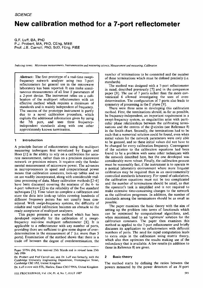
This difficulty corresponds to the geometrical problemof finding a point in the complex plane by its distancefrom two other (fixed) points. When these three pointsare nearly colinear, the position of the unknown point isill-determined in the direction perpendicular to the linethrough the two fixed points. Fig. 1 illustrates this by
Q- centre
Fig. 1 Intersection of circles defining a Q-centre
Diagram indicates an ill-defined intersection requiring additional information.
circles intersecting at a shallow angle giving an ill-definedintersection. To cure this problem, another piece of infor-mation is introduced. This is provided by a knowledge ofthe magnitude of the reflection coefficient | F T | of theoffset termination. This magnitude is available to at leastthe required accuracy of ±0.1 dB. There are then onlythree independent variables, and the equations fk = 0 are
596 IEE PROCEEDINGS, Vol. 134, Pt. A, No. 7, JULY 1987
overdetermined most of the time. They can then besolved in a least-squares fashion for Re (c), Im (c) andarg r r . This is the calibration method used for theresults presented in this paper and Reference 8.
4 Application to reflectometers with differentnumbers of ports
The calibration method described exploited the over-determination in the 7-port reflectometer to allow areduction in the number of standards needed. In this, it issimilar to the 6 to 4 port reduction [2] which is wellestablished for 6-port reflectometers and can be extendedto 7 ports. However, the method described here hasproved to lead to simpler numerical algorithms and hasbeen a reliable method of calibrating 7-port reflec-tometers in cases where the parameters of the networkwere not known well enough to allow the 6 to 4 portmethod to converge. It is of interest to see how thismethod is related to the network's degree of over-determination, by considering networks with fewer andmore ports.
In the 6-port reflectometer there is one degree of over-determination in the equations, as the modulus of theunknown reflection coefficient is found independentlyfrom its real and imaginary parts. This means that thenew calibration method can be adopted. However, thereare now only three equations of the form /k = 0 (k = 1 to3), but still 4 unknowns: Re (FT), Im ( r r ) , Re (c), Im (c).Thus, further information is needed before all these canbe evaluated. There are two ways to do this: first, ratherthan using a totally unknown termination, one with aknown magnitude but unknown phase may be used, asdescribed in the preceding Section. This then leaves onlythree unknowns, and the three equations in fk can beused to find their values. Alternatively, the number ofunknown connections may be increased. Each unknowntermination introduces two further unknowns (the realand imaginary parts of its reflection coefficient) but alsoprovides a further three functional equations, gk corres-ponding to the functional/k for the first unknown termi-nation. Thus, if one additional termination is added, thesix unknown variables can be found using the six equa-tions in fk and gk. This method can be seen as a counter-part to the 6 to 4 port reduction.
The 5-port reflectometer cannot be calibrated usingthis new method, as each unknown termination intro-duces two further unknown variables as before, but onlytwo equations in /k for k = 1, 2. This would be expectedas there is no overdetermination of F in the measurementequations.
It is of interest to enquire, if the degree of over-determination is increased by using more than 7 ports,could the number of terminations be reduced from fourto three. The answer is no, because the calibrationmethod breaks down because, with only three termina-tions, the constants xk, yk, wk and zk cannot be found ineqn. 6. However, adaptations of the method should bepossible to allow fewer of the four terminations to beknown exactly, because now 5 equations in fk(k = 1 to 5)are available.
5 Alternative formulation for unit magnitudestandards
The preceding discussion presumes the use of frequency-independent standards. These are particularly desirablefor applications with swept-frequency sources, or where
the source frequency is not precisely determined but onlyrepeatable. However, there may be occasions when theconvenience of a sliding load as a standard outweighs theadvantages of frequency independence. The most usualload favoured in this case is a sliding short circuit. Asdiscussed in Appendix 12.2, the number of standards andterminations is unchanged, but the exact method of solu-tion has to be modified. However, an iterative solution isagain employed. Again three standards are needed, withone unknown termination in addition for a 7-port reflec-tometer, or two for a 6-port.
6 Extra calibration steps
The 7-port reflectometer calibration method describedhere has been implemented in a prototype real-timeswept-frequency network analyser system. This systemuses a different representation of the calibration con-stants to enable rapid calibration of reflection coefficientsfrom the power readings. For this, all the eqns. 1 arecombined into a matrix form:
(10)
r =
where1
F*FRe(F)Im(F)
P is the vector of power readings given in row form as
and F is the 5 x 4 matrix
(11)
Foe
1elelelel
c'd*d\d%dUt
*cd*d2
d3
dUt
22*i
2*2
2*32*4
ReReReReRe
(*)(d(d(d(d
i )
2)
3)
4 )
2- 2 e- 2 e- 2 e- 2 e
Im(c)! Im (<*i)2 I m (d)
3 I m ( d j4 Im (d d
(12)
The constant of proportionality depends on the powerthat is incident on the device under test. The reflectioncoefficients are calculated as the elements of the vector F,provided that an inverse Y can be found for the matrix F,so that
F=YP (13)
where Y is a matrix (not necessarily square) with rows yt.If the system is a 6-port, then the matrix F is only
4 x 4 and, provided that it is not singular, then a uniqueinverse F~1 = Y exists. However, for the 7-port there isno unique solution to finding a matrix Y such thatYF = I. Instead, the extra information given by theseventh port allows us to optimise Y to provide themaximum accuracy in the results.
Matrix theory indicates that there are four degrees.offreedom in choosing Y. Appendix 12.1 gives a simpleargument why it should be chosen such that y\yi shouldbe minimised. Using this criterion, it is shown in Appen-dix 12.3 that the 5 x 4 matrix can be partitioneduniquely to provide an optimum solution using matrixinversion.
However, for computation with single precision* it hasbeen more convenient to mount an attack on theproblem in a different way. One of the rows of F isdeleted to form an invertable matrix B. A column ofzeros may be added to the inverted matrix, to form a
IEE PROCEEDINGS, Vol. 134, Pt. A, No. 7, JULY 1987 597
candidate for a 5 x 4 matrix Y such that YF = I. Thesefive candidate Y matrices are then weighted in such away as to minimise the scalar product of each row. Thisgives the desired Y which minimises the variance in eachelement of F.
7 Application of the new method
The standard terminations available were a commercialAPC-7 short/open circuit, a homemade offset shortcircuit and a matched load. The APC-7 short/opencircuit is specially constructed so that there is com-pensation in the short for the shielded open circuit's dis-continuity capacitance. The phase difference between thetwo reflections is 180° ± 1° from 2 to 12 GHz (as mea-sured using an HP8409 network analyser).
The homemade offset short circuit was made by repla-cing the dielectric bead of an APC-7 connector by a solidbrass plug. The length of this short circuit is 4.67 mm,making the difference in length between it and the com-pensated short circuit 3.48 mm. The phase shift it givesvaries from 35° at 4.5 GHz to 105° at 12 GHz. The 35°phase shift has been found to be adequate. An APC-7connector with no inner conductor behind the dielectricbead serves as an offset open circuit. This provides aphase shift of 120° at 5 GHz and 45° at 1.5 GHz.Between them, these improvised terminations cover therange 1.5 to 16 GHz.
The matched load has distributed loss using a taperedpiece of iron loaded plastic in a 20 cm length 7 mmcoaxial airline.
8 Results
The refiectometer was calibrated over 4 to 4.5 GHz and3.75-7.5 GHz using the new method with short/opencircuit, matched load and offset short circuit standards.Measurement of the offset open circuit then gave a checkof the accuracy of the calibration (remeasuring the cali-bration standards just proves the repeatability of therefiectometer system components). Fig. 2 is a photographof the real-time reflectometer's display screen while mea-suring the offset open circuit over 4-4.5 GHz. The phaseof the reflection of the offset open circuit is sufficientlydifferent from the phases of the calibration terminations,so that an effective check can be made on the value of thecalibration constants obtained by forcing the fit to thecalibration equations.
The accuracy is within +0.1 dB over most of therange. There is a weak spot at around 4 GHz, where theaccuracy falls to 0.5 dB. At these points, although noother sign of ill-conditioning is present, the equation-solving iterations take a long time to converge toresiduals of only 0.0001. This may be due to an inter-action between a particular value of c and of F r , but thishad not been properly explored. The value of 0.0001 inthe residual implies errors of about 0.005 in the measure-ment of the offset open circuit used as a check. At otherfrequencies, convergence is very satisfactory, even thoughthe symmetry of the 7-port design means that two of thefunctionals fk approach ill-conditioning simultaneously.The calibrations are, however, more sensitive to errors inpower-reading data when the yk are small. The 3.75 to7.5 GHz calibration produces slightly worse results(±0.01 dB errors) because of the problems in the preci-sion of repeating a frequency for a given voltage on thevoltage-controlled oscillator. The degradation around4 GHz is around 1 dB.
• • • •mmm
Fig. 2 Display measuring offset open circuit
Frequency range 4-4.5 GHza Bode plot: upper lines gives reflection around 0 dB, upper trace: amplitude,lower trace: phaseb Polar plot: outer circle gives unity reflection coefficient
A full calibration run for a 128 point frequency rangetakes only 10 min if 100 readings are taken at each fre-quency point.
9 Conclusion
The calibration method presented has been speciallydesigned for use with a 7-port refiectometer and com-bines a number of attributes making it attractive whencompared with other published methods. It usesfrequency-dependent standard terminations in coaxialline. Confidence in the calibration for a medium accuracyinstrument is increased by the use of the short circuit,open circuit and match as 'fixed points'. This methodrequires the minimum possible operator effort during arefiectometer calibration, the three standard terminationsrequired for a superheterodyne automatic networkanalyser are connected to the refiectometer, followed bythe single offset open- or short-circuit termination thathas a usable frequency range of 3 : 1. The technique usesalgorithms which are readily implemented on micro-processors.
The overwhelming advantage of using this method fora refiectometer is that only approximately known circuitparameters are required initially, and, by relying on over-determination in solution to the equations with onlythree standards, the convergence in the solution is foundto be stable. The method reliably and accurately cali-
598 IEE PROCEEDINGS, Vol. 134, Pt. A, No. 7, JULY 1987
brated the reflectometer, whereas the numerical solutionto the 6- to 4-port reduction method, which uses thesame number of standards and relies similarly on over-determination, was found by the authors to frequentlyfail at various critical frequencies.
10 Acknowledgments
The authors are indebted to the Paul Instrument Fundfor a major grant and to A. Bailey for continual encour-agement. They are also indebted to Marconi InstrumentsLtd. (in particular P. McAllister) who helped significantlywith sources and detectors and supported a CASEstudent (G. Luff) for this work.
11 References
1 ENGEN, G.F., and HOER, C.A.: 'Application of an arbitrary6-port junction to power measurement problems', IEEE Trans.,1972, IM-21, pp. 470-474
2 ENGEN, G.F.: 'Calibrating the six-port reflectometer by means ofsliding terminations', ibid., 1977, MTT-26, (12), pp. 951-957
3 SOMLO, P.I., and HUNTER, J.D.: 'A six port reflectometer and itscomplete characterization by convenient calibration procedures',ibid., 1982, MTT-30, (2), pp. 186-192
4 LUFF, G.F., PROBERT, P.J., and CARROLL, J.E.: 'Real-time six-port reflectometer', IEE Proc. H, Microwaves, Opt. & Antennas,1984,131,(3), pp. 186-190
5 LI, S.H., and BOSISIO, R.G.: 'Calibration of multiport reflec-tometers by means of fouropen/short circuits', IEEE Trans., 1982,MTT-30, (7), pp. 1085-1090
6 HODGETTS, T.E., and GRIFFIN, E.J.: 'A unified treatment of thetheory of 6-port reflectometer calibration using the minimum ofstandards'. RSRE, Malvern, Report 83003, 1983
7 LUFF, G.F., PROBERT, P.J., and CARROLL, J.E.: 'A real-timeswept-frequency multi-port reflectometer'. 14th European Micro-wave Conference proceedings, September 1984
8 LUFF, G.F., PROBERT, P.J, and CARROLL, J.E.: 'Dual 7-portautomatic network analyser with swept-frequency real-timeresponse', IEE Proc. A, 1987,137, (7), pp. 000-000
9 PROBERT, P.J., and CARROLL, J.E.: 'Design features on multi-port reflectometers', IEE Proc. H, Microwaves, Opt. & Antennas,1982,129, (5), pp. 245-252
10 LUFF, G.F.: 'A real time microwave network analyser using multi-port techniques'. Ph.D. dissertation, University of Cambridge, 1986
12 Appendixes
12.1 Optimisation criterion from consideration oferrors
A more detailed discussion of errors is given elsewhere[9, 10]. However, eqn. 10 et seq. shows that, if an inversecan be found, we may write
r = YP (14)where F and P are column vectors expressed in row form,these give
mean-square errors in the reflection coefficients are
= (P1,P2,P3,P4) (15)
giving the normalised power measurements, and the com-ponents of the reflection coefficient are expressed as
r = [i , r * r , Re (r), im (F)] (16)
Taking the ith component
ri = T.jyijPj (i7)
If the errors in the power readings are all independent,then, on average, dPj over a number of readings willaverage to zero. However, taking <<5P2> = e, for all thepossible combinations of powers over all possible reflec-tion coefficients (no one port being singled out to alwaysgive low power or always have high power), then the
> = 5 > « e (ig)This provides a simple rationale for minimising the pro-ducts YJ yfj f°r e a c h r o w °f Y so that the minimum meansquare error is found in F,.
This result generalises for Y as a 4 x 5 matrix with 5elements in P and provides the rationale for the opti-misation arguments in Appendix 12.3.
12.2 Formulation of the calibration equations for unitmagnitude standards
The details of the method of solution alter when all thestandards are of unit magnitude as then both eqns. 6 and7 must be used in the initial stage of the procedure. NowF1? F 2 , F3 are the standard terminations, and they allhave unit magnitudes. Instead of the eqn. 6, the solutionsto eqn. 2 can be written in matrix form:
G — AW (]Q\
where
\Q'J
/ wk + zk
\ yk
\I and
/
A ="11
.1
ReReRe
r\r2F3
ImImIm
rlr2f3
The matrix A contains only the reflection coefficients ofthe standard terminations so that the inverse A~l onlyneeds to be evaluated once for each frequency. With ther t all of unit magnitude they lie on a circle. Hence, theycannot be collinear, so that the matrix A is never singu-lar. The values wk and zk can be separated by using eqn.7:
(20)
(21)
Define uk from
«* = wk + *k
Then
w* = [uk + / -
zk = uk- wk
- x2 - (23)
(24)
The choice of sign of the square root in eqn. 23 must bemade from prior knowledge of the network's parameters(the network used in this work has for example e2 > d*dby design) or by making measurements of an approx-imate match.
The iteration can no longer use eqns. 7 to correct theestimate as before because they have already been used.However, for each additional termination an equation hN
can be quoted:
hN = T% TN - Re (F*)2 - Im = 0 (25)
As in measurements, F*F is found independently fromRe (F) and Im (F), this equation can be used in the iter-ative process.
In this calibration the constants wk etc. have been esti-mated, using only the three standards. Hence, we cannow measure the unknown reflection coefficient. Thus,we have measurements of the parameters to put into eqn.25 for hN and need use the iterative process only tocorrect out initial guesses of Re (c) and Im (c).
There is then one equation or target function hN = 0for each unknown termination and two unknowns Re (c)
IEE PROCEEDINGS, Vol. 134, Pt. A, No. 7, JULY 1987 599
and Im (c). So again, 3 standards and two 'unknown' ter-minations are needed to calibrate a 6-port reflectometer.
Computer simulations of this calibration method indi-cated that solutions were possible, even when all termina-tions had unit magnitude, as long as their phases werenot too close to one another. This would be difficult tomaintain over a broad band, as an uneven distribution ofphase at one frequency could cluster at another fre-quency.
Because of the extra redundancy, it can be shown that7-port solutions exist for only one unknown terminationbut this termination must have a nonunit modulus for itsreflection coefficient. The obvious choice of F 4 = 0 leadsto ill-conditioning of the calibration equations, when anyof the yk approaches 0 as discussed earlier (Section 3).Computer simulations indicated that the best condi-tioned solutions result if F 4 has a magnitude greater thanone and is assymetrically disposed in comparison withthe other terminations in the complex plane.
In all cases, the discontinuous behaviour of the square-root function in eqns. 13 can cause the numerical solu-tions of the target functions to fail.
12.3 Optimum choice of the matrix YAs discussed in the main text, there are four ways inwhich a matrix Y may be formed from the 5 x 4 matrix Fsuch that
FY = (26)
We examine here the optimum way to form that matrix.Choose any one column of the matrix Y and the corre-
sponding row of the matrix F. The rows and columns ofthe matrices are reordered so that this row and columnare the first row (row vector a') or the first column(column vector x). The remaining matrix part of Y and Fare then 4 x 4 matrices Z and B so that the form of theproblem is given by
-A = i
This expands so
xa' + ZB = I
Given then the choice of a and hence B,
Z=(I-xat)B-1
(27)
(28)
(29)
The choice of x or a depends on the criteria that are tobe used. Appendix 12.1 gives a simple argument as towhy the choice should be made so that ^{j; should beminimised. Accepting this criteria, it is possible to differ-entiate
with respect to x, to show that[-1 D - l
Kj1'
or, in vector form,
[1 + a'B-l(B-l)'d]x =
(30)
(31)
(32)
For any chosen a, eqn. 32 gives an optimum x whichminimises errors in the solution for F.
600 IEE PROCEEDINGS, Vol. 134, Pt. A, No. 7, JULY 1987