STIH) Technical Information TI_45_2010_17_01_01.fm englisch / English New chain saw STIHL MS 241 C-M – Series 1143 Contents 1. STIHL M-Tronic 2. Technical description 3. Specifications 4. Special tools and service accessories 5. Servicing 45.2010
Transcript
STIH)
Technical Information 45.2010
New chain saw STIHL MS 241 C-M – Series 1143
Contents1. STIHL M-Tronic2. Technical description3. Specifications4. Special tools and service accessories5. Servicing
TI_45_2010_17_01_01.fm englisch / English
Page 2 Technical Information 45.2010
The chain saw MS 241 C-M is the compact new real professional. It is the first STIHL chain saw equipped with the fully electronic M-Tronic engine management system as standard.
With an innovative engine concept and filter system as well as the new 3/8" Picco Super saw chain, it is especially powerful, economical, clean and low-maintenance. This makes it the ideal tool for professional users in forestry, agriculture and construction as well as gardening. The new chain saw is excellent for cutting firewood, felling and tending stands, but also for craft woodwork.
The strengths:
– Fully electronic engine management system for constantly optimal performance
– modern, low-emission 2-MIX engine with reduced fuel consumption – the MS 241 C-M is the first professional saw in this performance class worldwide to comply with the EU II emissions standard
– Air filter with pre-separator for substantially longer service life
– Outstanding control and rigidity with a low level of vibration
– Very service-friendly thanks to a one-piece shroud with three quick-action locks and an air filter with a bayonet-type lock
Besides the standard MS 241 C-M version with M-Tronic, the following additional equipment versions are available depending on the market:
– MS 241 C-BEM with quick chain tensioner, ErgoStart manual fuel pump and M-Tronic
– MS 241 C-MQ with M-Tronic and the QuickStop Super chain brake system
– MS 241 C-M VW with M-Tronic as well as carburetor and handle heating
1. STIHL M-TronicThe MS 241 C-M is the first professional STIHL chain saw equipped with the new, fully electronic M-Tronic engine management system. It regulates the ignition timing and electronically adjusts the fuel flow, taking external conditions into account.
Electronic cold / warm start detection permits a position "Start }" on the Master Control lever for starting the chain saw. Simple starting with fewer pulls of the starter rope, without switching from "cold start" to "warm start". The very good acceleration is realized using the electronic controller. By means of the engine temperature and speed, the control unit continually checks the operating state of the chain saw and adjusts the fuel flow so that optimal engine power is always available. The electronic memory (memory function) remembers the settings from the last time the machine was used. Thus if the machine is restarted under the same general conditions, the full power of the engine is available immediately.
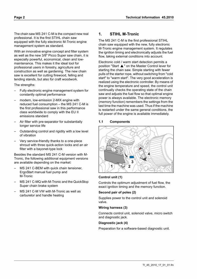
1.1 Components
Control unit (1)Controls the optimum adjustment of fuel flow, the exact ignition timing and the memory function.
Second pair of poles (2)Supplies power to the control unit and solenoid valve.
Wiring harness (3)Connects control unit, solenoid valve, micro switch and diagnostic jack.
Diagnostic jack (4)Preparation for a software-based diagnostic unit.
2410
TI01
0 KN
4
13
2
TI_45_2010_17_01_01.fm
Technical Information 45.2010 Page 3
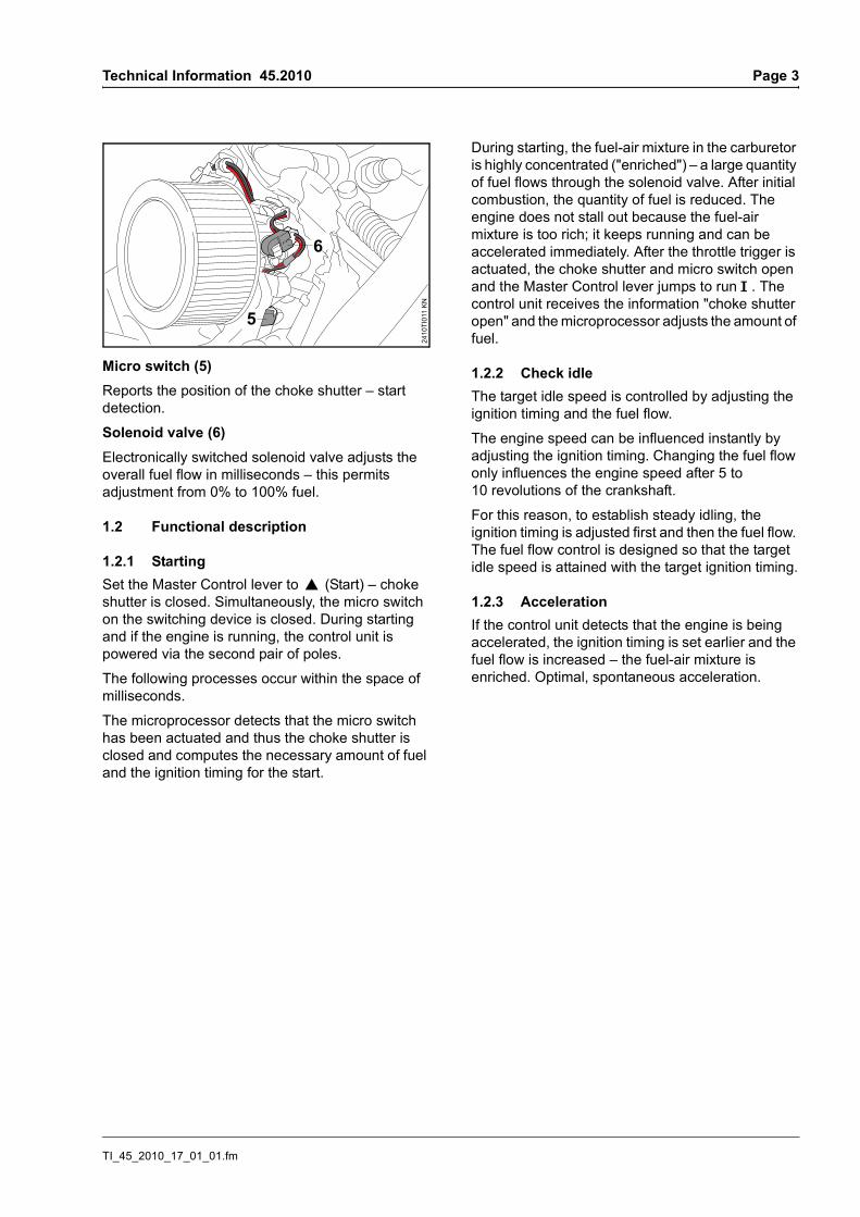
Micro switch (5)Reports the position of the choke shutter – start detection.
Solenoid valve (6)Electronically switched solenoid valve adjusts the overall fuel flow in milliseconds – this permits adjustment from 0% to 100% fuel.
1.2 Functional description
1.2.1 StartingSet the Master Control lever to } (Start) – choke shutter is closed. Simultaneously, the micro switch on the switching device is closed. During starting and if the engine is running, the control unit is powered via the second pair of poles.
The following processes occur within the space of milliseconds.
The microprocessor detects that the micro switch has been actuated and thus the choke shutter is closed and computes the necessary amount of fuel and the ignition timing for the start.
During starting, the fuel-air mixture in the carburetor is highly concentrated ("enriched") – a large quantity of fuel flows through the solenoid valve. After initial combustion, the quantity of fuel is reduced. The engine does not stall out because the fuel-air mixture is too rich; it keeps running and can be accelerated immediately. After the throttle trigger is actuated, the choke shutter and micro switch open and the Master Control lever jumps to run F . The control unit receives the information "choke shutter open" and the microprocessor adjusts the amount of fuel.
1.2.2 Check idleThe target idle speed is controlled by adjusting the ignition timing and the fuel flow.
The engine speed can be influenced instantly by adjusting the ignition timing. Changing the fuel flow only influences the engine speed after 5 to 10 revolutions of the crankshaft.
For this reason, to establish steady idling, the ignition timing is adjusted first and then the fuel flow. The fuel flow control is designed so that the target idle speed is attained with the target ignition timing.
1.2.3 AccelerationIf the control unit detects that the engine is being accelerated, the ignition timing is set earlier and the fuel flow is increased – the fuel-air mixture is enriched. Optimal, spontaneous acceleration.
6
2410
TI01
1 KN
5
TI_45_2010_17_01_01.fm
Page 4 Technical Information 45.2010
1.2.4 Full throttleA regulating sequence will be initiated only if the chain saw is operated for approx. 2 seconds under uniform conditions, e.g., cutting to length, at a speed between 8000 rpm and 11200 rpm.
The solenoid valve closes for approx. 0.1 seconds – the current fuel-air mixture is made leaner.
The speed change due to the brief leaning of the mix is so slight as to be imperceptible to the user.
The resulting engine speed pattern is analyzed by the microprocessor.
The following results are possible:
Engine speed increases. The mix was too rich before the solenoid valve
closed – the fuel flow is reduced for next phase of operation
Engine speed decreases. The mix was too lean before the solenoid valve
closed – the fuel flow is increased for the next phase of operation
Engine speed does not change. The current carburetor setting is optimal – the
current setting will be maintained
1.2.5 Maximum speedThe maximum permissible speed is kept constant by controling the fuel-air mixture and the ignition timing.
1.3 AdvantagesEasy starting – With M-Tronic there is only one start position on the Master Control lever because the system detects cold or warm starts and electronically computes the exact fuel flow. Starting with a few pulls of the starter rope and immediate full throttle.
Permanent optimum engine performance – By means of the engine temperature and speed, the control unit continually checks the operating state of the chain saw and adjusts the fuel flow for constant optimum engine performance.
Very good acceleration –The MS 241 C-M accelerates spontaneously and quickly by virtue of electronic ignition timing control and fuel flow adjustment.
No manual carburetor adjustments – M-Tronic electronically adjusts the fuel-air mixture in the carburetor: for all operating states such as start, idle, part throttle and full throttle as well as taking into account the external conditions, e. g., use at varying altitudes, changing temperatures or fuel quality (caloric value – energy content of the fuel, alcohol content, knock resistance).
Memory function (electronic memory) – M-Tronic remembers, for an unlimited period of time, the settings from the last time the saw was used and retrieves them the next time the chain saw is started. Thus full engine power is available immediately each time the machine is started under the same external conditions.
TI_45_2010_17_01_01.fm
Technical Information 45.2010 Page 5
1.4 Starting / stopping the engine
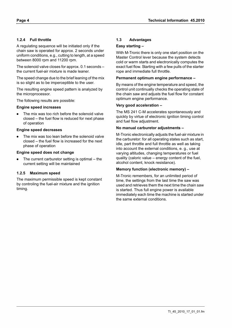
1.4.1 Positions of the Master Control lever
Adjusting the Master Control leverTo adjust the Master Control lever from run F to start }, press and hold down the throttle trigger lockout and throttle trigger simultaneously – set Master Control lever to start } and simultaneously release the throttle trigger and throttle trigger lockout.
Simultaneously pressing the throttle trigger lockout and blipping the throttle trigger causes the Master Control lever to jump from the start } position to run F.
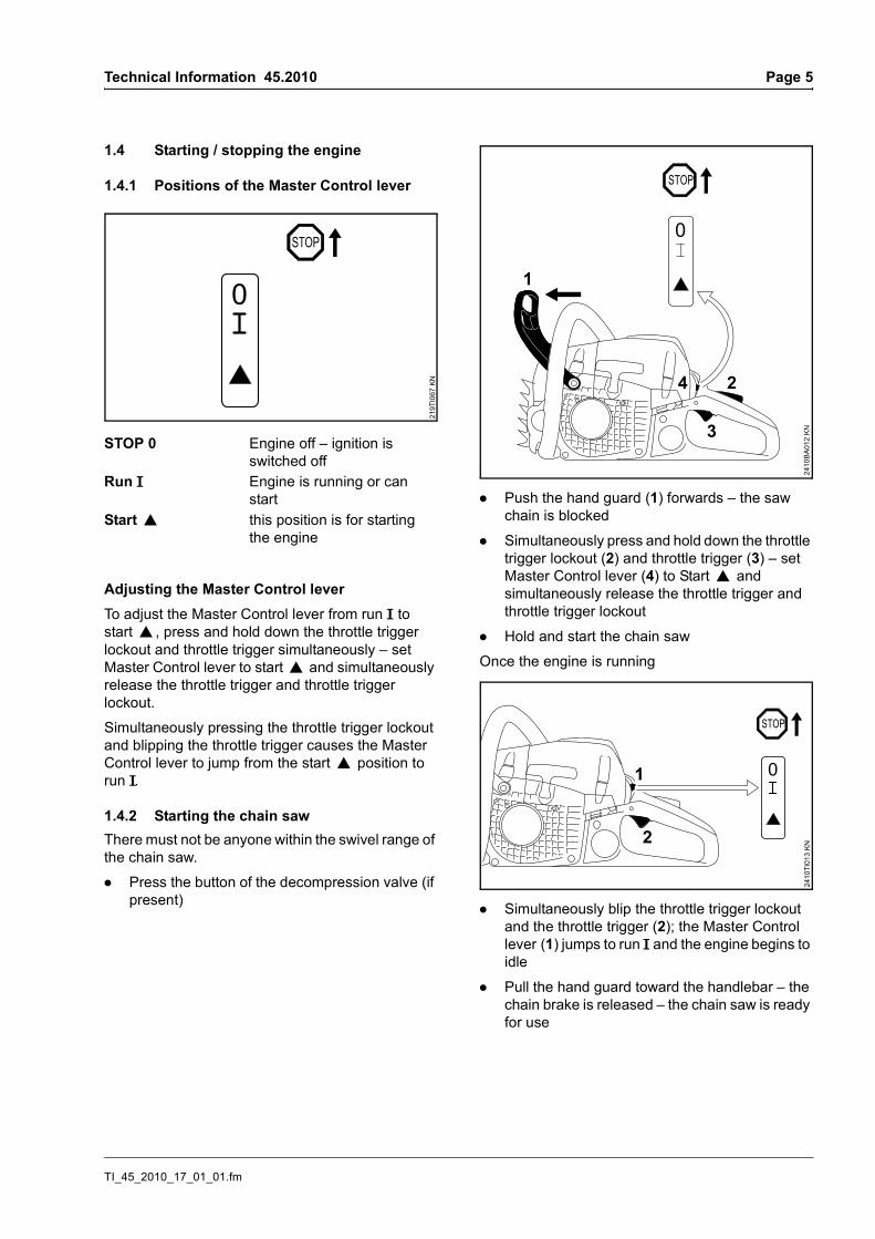
1.4.2 Starting the chain sawThere must not be anyone within the swivel range of the chain saw.
. Press the button of the decompression valve (if present)
. Push the hand guard (1) forwards – the saw chain is blocked
. Simultaneously press and hold down the throttle trigger lockout (2) and throttle trigger (3) – set Master Control lever (4) to Start } and simultaneously release the throttle trigger and throttle trigger lockout
. Hold and start the chain saw
Once the engine is running
. Simultaneously blip the throttle trigger lockout and the throttle trigger (2); the Master Control lever (1) jumps to run F and the engine begins to idle
. Pull the hand guard toward the handlebar – the chain brake is released – the chain saw is ready for use
STOP 0 Engine off – ignition is switched off
Run F Engine is running or can start
Start } this position is for starting the engine
STOP
0
219T
I067
KN
1
3
24
2410
BA
012
KN
2
124
10TI
013
KN
TI_45_2010_17_01_01.fm
Page 6 Technical Information 45.2010
1.4.3 If the engine does not startThe starter grip may not have been pulled briskly and forcefully; the fuel-air mixture is probably too rich (engine is flooded).
. Move the Master Control lever to run F
. Hold and start the chain saw
or:
. Remove and dry the spark plug
. Move the Master Control lever to the stop position 0
. Crank the engine several times with the starter – to clear the combustion chamber
. Refit the spark plug
. Move the Master Control lever to run F
Hold and start the chain saw
2. Technical description
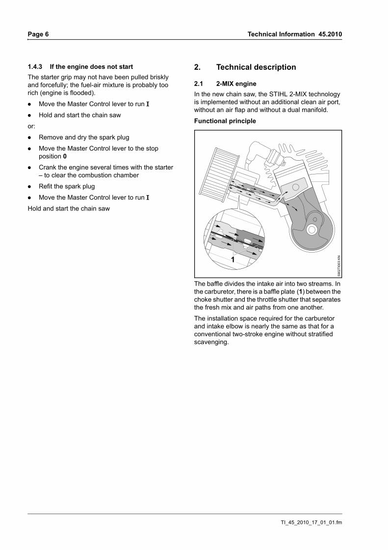
2.1 2-MIX engineIn the new chain saw, the STIHL 2-MIX technology is implemented without an additional clean air port, without an air flap and without a dual manifold.
Functional principle
The baffle divides the intake air into two streams. In the carburetor, there is a baffle plate (1) between the choke shutter and the throttle shutter that separates the fresh mix and air paths from one another.
The installation space required for the carburetor and intake elbow is nearly the same as that for a conventional two-stroke engine without stratified scavenging.
1
5902
TI00
3 K
N
TI_45_2010_17_01_01.fm
Technical Information 45.2010 Page 7
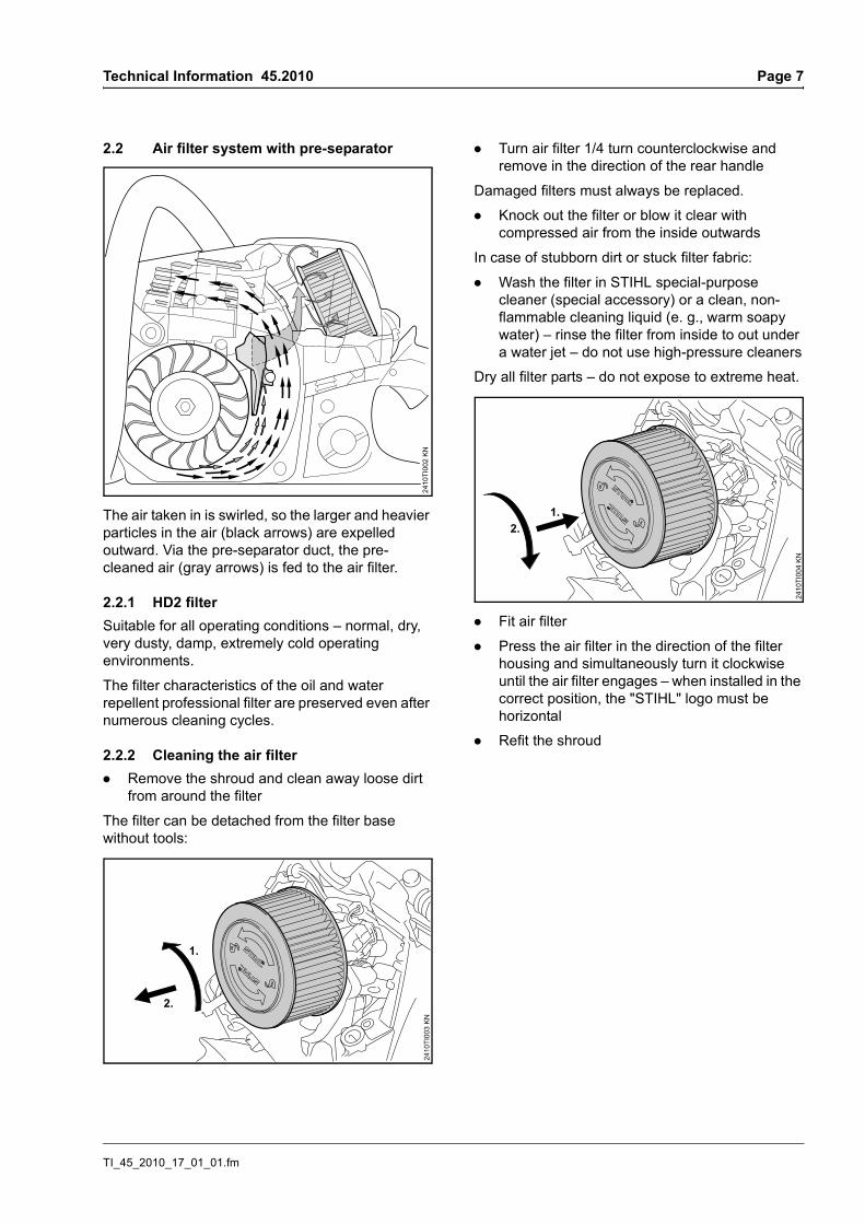
2.2 Air filter system with pre-separator
The air taken in is swirled, so the larger and heavier particles in the air (black arrows) are expelled outward. Via the pre-separator duct, the pre-cleaned air (gray arrows) is fed to the air filter.
2.2.1 HD2 filterSuitable for all operating conditions – normal, dry, very dusty, damp, extremely cold operating environments.
The filter characteristics of the oil and water repellent professional filter are preserved even after numerous cleaning cycles.
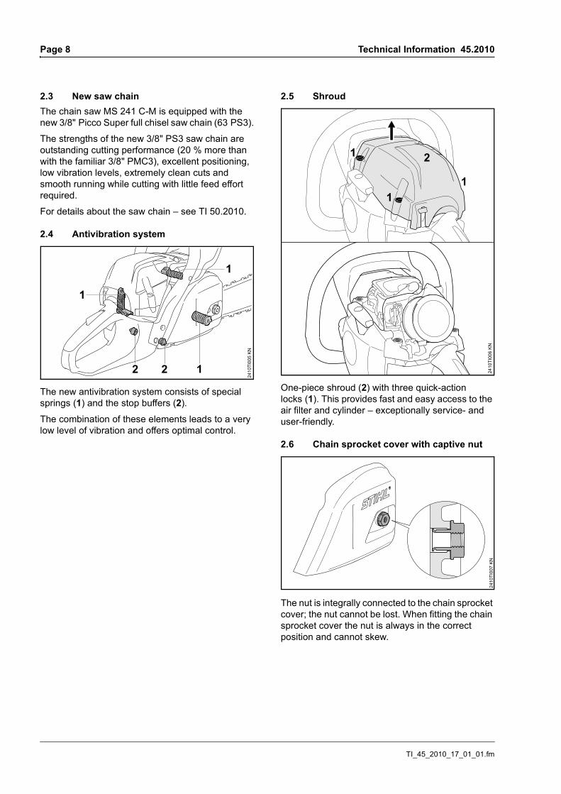
2.2.2 Cleaning the air filter. Remove the shroud and clean away loose dirt
from around the filter
The filter can be detached from the filter base without tools:
. Turn air filter 1/4 turn counterclockwise and remove in the direction of the rear handle
Damaged filters must always be replaced.
. Knock out the filter or blow it clear with compressed air from the inside outwards
In case of stubborn dirt or stuck filter fabric:
. Wash the filter in STIHL special-purpose cleaner (special accessory) or a clean, non-flammable cleaning liquid (e. g., warm soapy water) – rinse the filter from inside to out under a water jet – do not use high-pressure cleaners
Dry all filter parts – do not expose to extreme heat.
. Fit air filter
. Press the air filter in the direction of the filter housing and simultaneously turn it clockwise until the air filter engages – when installed in the correct position, the "STIHL" logo must be horizontal
. Refit the shroud
2410
TI00
2 K
N
1.
2.
2410
TI00
3 KN
2.1.
2410
TI00
4 KN
TI_45_2010_17_01_01.fm
Page 8 Technical Information 45.2010
2.3 New saw chainThe chain saw MS 241 C-M is equipped with the new 3/8" Picco Super full chisel saw chain (63 PS3).
The strengths of the new 3/8" PS3 saw chain are outstanding cutting performance (20 % more than with the familiar 3/8" PMC3), excellent positioning, low vibration levels, extremely clean cuts and smooth running while cutting with little feed effort required.
For details about the saw chain – see TI 50.2010.
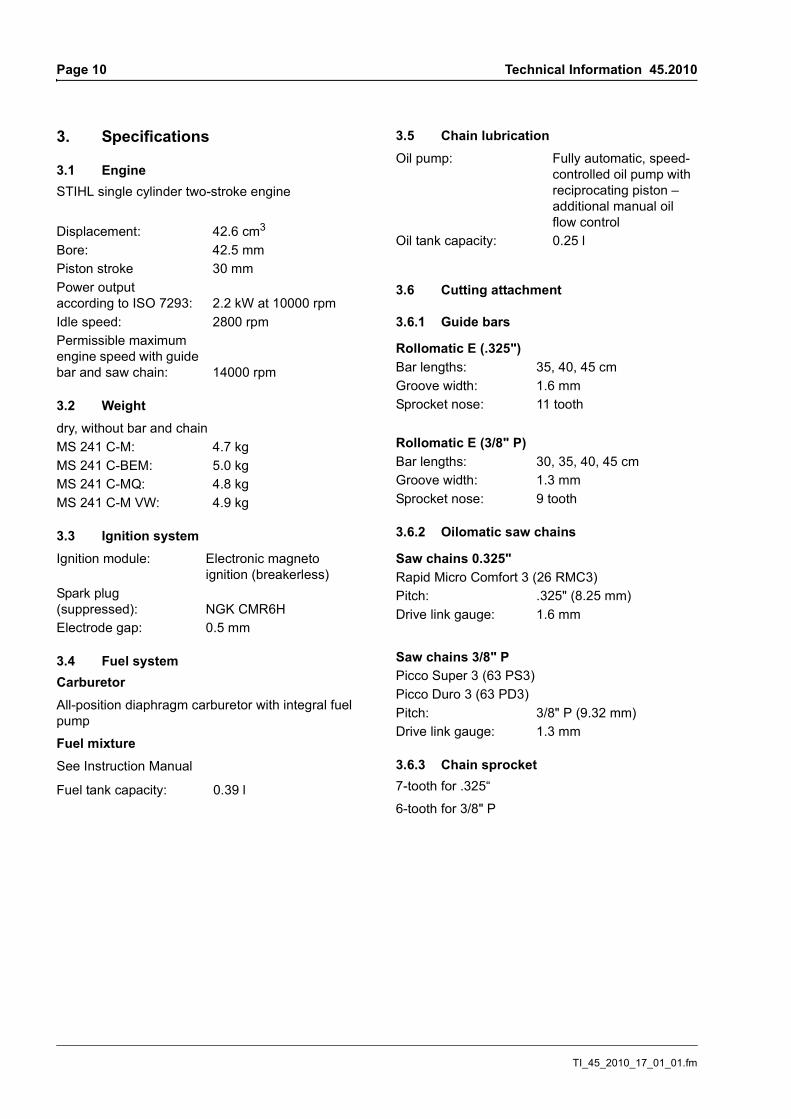
2.4 Antivibration system
The new antivibration system consists of special springs (1) and the stop buffers (2).
The combination of these elements leads to a very low level of vibration and offers optimal control.
2.5 Shroud
One-piece shroud (2) with three quick-action locks (1). This provides fast and easy access to the air filter and cylinder – exceptionally service- and user-friendly.
2.6 Chain sprocket cover with captive nut
The nut is integrally connected to the chain sprocket cover; the nut cannot be lost. When fitting the chain sprocket cover the nut is always in the correct position and cannot skew.
2
2410
TI00
5 KN
12
1
1
2410
TI00
6 K
N24
10TI
007
KN
TI_45_2010_17_01_01.fm
Technical Information 45.2010 Page 9
2.7 QuickStop Super chain brake system(MS 241 C-MQ)
The additional brake system for additional safety from STIHL: This unique safety feature ensures additional user protection without additional steps and levers during:
– Starting
– Carrying
– Brief work breaks
FunctionIn this system, the clutch drum is always blocked unless the throttle trigger lockout is depressed.
The throttle trigger lockout simultaneously serves as actuator for the second chain brake system. When the throttle trigger lockout is depressed, the brake band releases the clutch drum.
When the throttle trigger lockout is released, the brake band clasps the clutch drum.
The chain brake can be triggered in three ways:
– Automatically by a sufficiently strong kickback – due to the mass inertia of the hand guard
– Manually by pressing the front hand guard towards the bar tip
– Manually by releasing the throttle trigger lockout on the rear handle
TI_45_2010_17_01_01.fm
Page 10 Technical Information 45.2010
3. Specifications
3.1 Engine STIHL single cylinder two-stroke engine
3.2 Weight
3.3 Ignition system
3.4 Fuel systemCarburetorAll-position diaphragm carburetor with integral fuel pump
Fuel mixtureSee Instruction Manual
3.5 Chain lubrication
3.6 Cutting attachment
3.6.1 Guide bars
3.6.2 Oilomatic saw chains
3.6.3 Chain sprocket7-tooth for .325“
6-tooth for 3/8" P
Displacement: 42.6 cm3 Bore: 42.5 mmPiston stroke 30 mmPower output according to ISO 7293: 2.2 kW at 10000 rpm Idle speed: 2800 rpmPermissible maximum engine speed with guide bar and saw chain: 14000 rpm
dry, without bar and chainMS 241 C-M: 4.7 kgMS 241 C-BEM: 5.0 kgMS 241 C-MQ: 4.8 kgMS 241 C-M VW: 4.9 kg
Saw chains 0.325"Rapid Micro Comfort 3 (26 RMC3)Pitch: .325" (8.25 mm)Drive link gauge: 1.6 mm
Saw chains 3/8" PPicco Super 3 (63 PS3)Picco Duro 3 (63 PD3)Pitch: 3/8" P (9.32 mm)Drive link gauge: 1.3 mm
TI_45_2010_17_01_01.fm
Technical Information 45.2010 Page 11
4. Special tools and service accessories
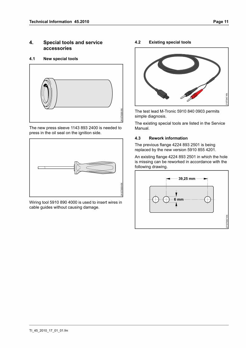
4.1 New special tools
The new press sleeve 1143 893 2400 is needed to press in the oil seal on the ignition side.
Wiring tool 5910 890 4000 is used to insert wires in cable guides without causing damage.
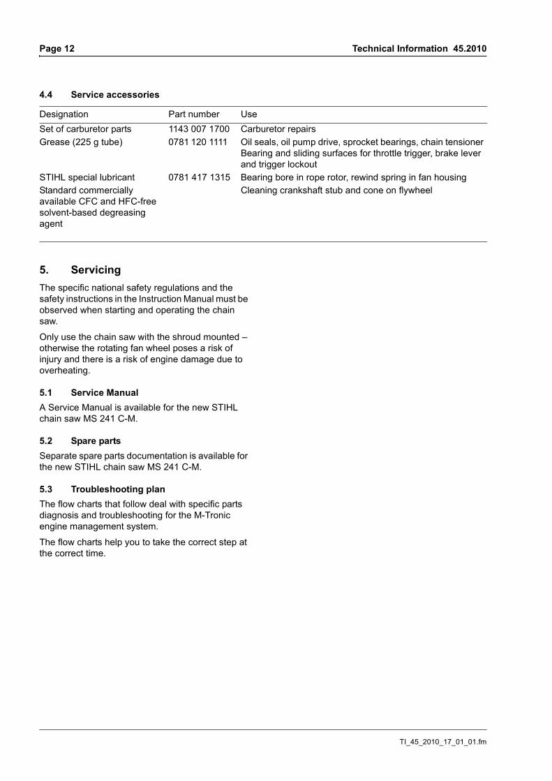
4.2 Existing special tools
The test lead M-Tronic 5910 840 0903 permits simple diagnosis.
The existing special tools are listed in the Service Manual.
4.3 Rework informationThe previous flange 4224 893 2501 is being replaced by the new version 5910 855 4201.
An existing flange 4224 893 2501 in which the hole is missing can be reworked in accordance with the following drawing.
2410
TI00
8 KN
2410
TI00
9 KN
219T
I047
KN
39,25 mm
2710
TI00
7 K
N
TI_45_2010_17_01_01.fm
Page 12 Technical Information 45.2010
4.4 Service accessories
5. ServicingThe specific national safety regulations and the safety instructions in the Instruction Manual must be observed when starting and operating the chain saw.
Only use the chain saw with the shroud mounted – otherwise the rotating fan wheel poses a risk of injury and there is a risk of engine damage due to overheating.
5.1 Service ManualA Service Manual is available for the new STIHL chain saw MS 241 C-M.
5.2 Spare partsSeparate spare parts documentation is available for the new STIHL chain saw MS 241 C-M.
5.3 Troubleshooting plan The flow charts that follow deal with specific parts diagnosis and troubleshooting for the M-Tronic engine management system.
The flow charts help you to take the correct step at the correct time.
Designation Part number UseSet of carburetor parts 1143 007 1700 Carburetor repairsGrease (225 g tube) 0781 120 1111 Oil seals, oil pump drive, sprocket bearings, chain tensioner
Bearing and sliding surfaces for throttle trigger, brake lever and trigger lockout
STIHL special lubricant 0781 417 1315 Bearing bore in rope rotor, rewind spring in fan housingStandard commercially available CFC and HFC-free solvent-based degreasing agent
Cleaning crankshaft stub and cone on flywheel
TI_45_2010_17_01_01.fm
Technical Information 45.2010 Page 13
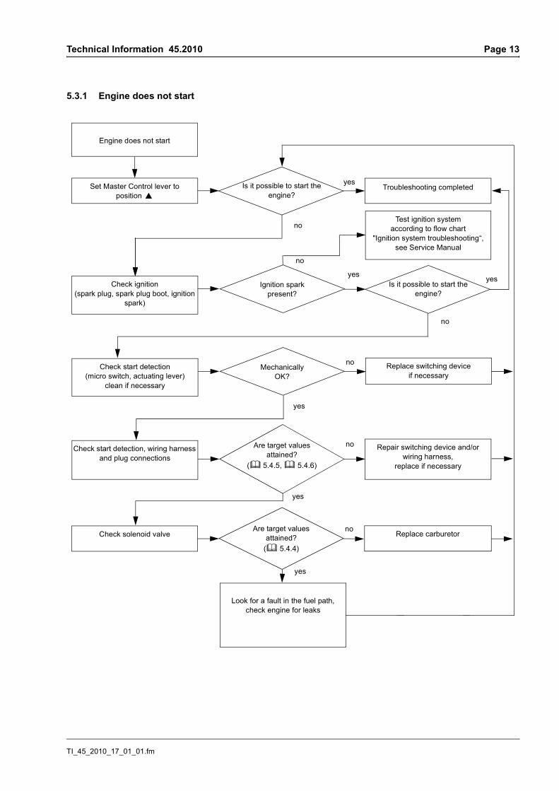
5.3.1 Engine does not start
Is it possible to start the engine?
no
Set Master Control lever to position }
Troubleshooting completed
Test ignition system according to flow chart
"Ignition system troubleshooting“, see Service Manual
Check start detection, wiring harness and plug connections
Are target values attained?
(b 5.4.5, b 5.4.6)
Repair switching device and/orwiring harness,
replace if necessary
no
Check solenoid valve Are target values
attained? (b 5.4.4)
Replace carburetor
yes
yes
no
TI_45_2010_17_01_01.fm
Page 18 Technical Information 45.2010
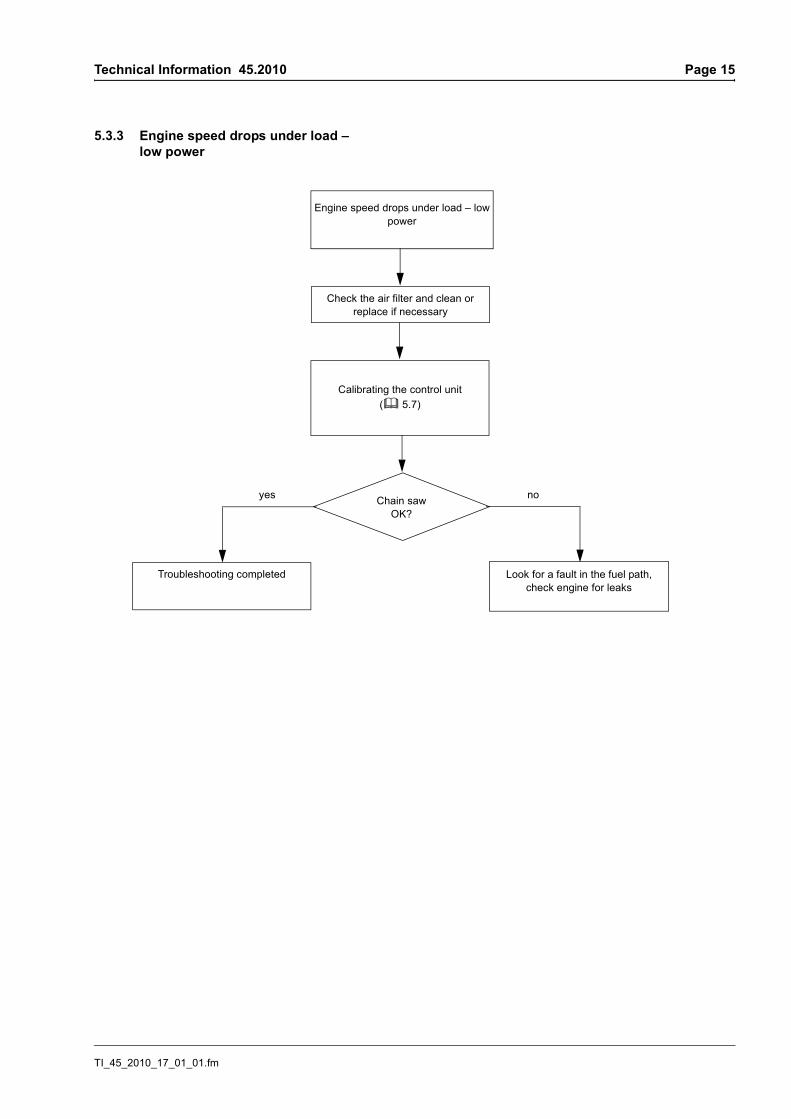
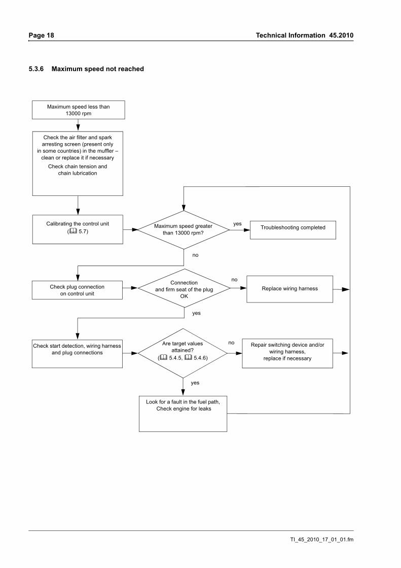
5.3.6 Maximum speed not reached
Check the air filter and spark arresting screen (present only
in some countries) in the muffler – clean or replace it if necessary
Check chain tension and chain lubrication
Calibrating the control unit(b 5.7)
Maximum speed greater than 13000 rpm?
Maximum speed less than 13000 rpm
Look for a fault in the fuel path, Check engine for leaks
no
Troubleshooting completedyes
Check plug connection on control unit
Connection and firm seat of the plug
OKReplace wiring harness
no
yes
yes
Check start detection, wiring harness and plug connections
Are target values attained?
(b 5.4.5, b 5.4.6)
Repair switching device and/orwiring harness,
replace if necessary
no
TI_45_2010_17_01_01.fm
Technical Information 45.2010 Page 19
5.4 Check M-Tronic
5.4.1 Ohmmeter and plug connectionsAn ohmmeter (multimeter) with a diode tester is required for the following test procedures.
To ensure a reliable contact:
– Use appropriate test probes
– Do not widen or bend plugs and connector tags
– Unplug and plug in plug connections by hand whenever possible in the direction of the connector tags – do not insert them on a slant or tilt or widen them
– Plug must be seated firmly
5.4.2 Plug connection to control unitA reliable connection must be ensured for communication between control unit, switching device and solenoid valve. If communication between control unit and solenoid valve is interrupted or faulty, the control unit does not initiate an ignition spark. Thus if there is no ignition spark, first check the plug connections and wiring harness between control device and solenoid.
. Remove shroud
. Remove any coarse dirt from around the control unit and the plug
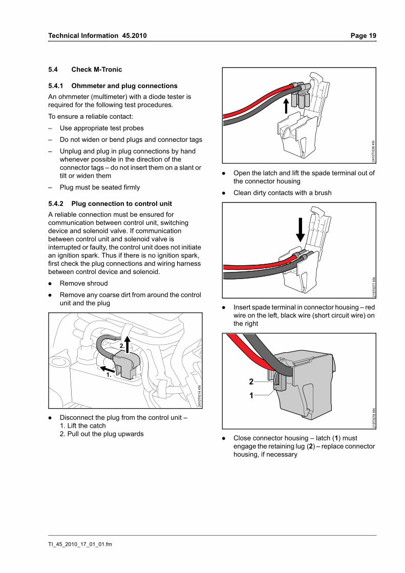
. Disconnect the plug from the control unit – 1. Lift the catch2. Pull out the plug upwards
. Open the latch and lift the spade terminal out of the connector housing
. Clean dirty contacts with a brush
. Insert spade terminal in connector housing – red wire on the left, black wire (short circuit wire) on the right
. Close connector housing – latch (1) must engage the retaining lug (2) – replace connector housing, if necessary
1.
2410
TI01
4 KN
2.
2410
TI03
8 K
N21
9TI0
77 K
N21
9TI0
78 K
N
12
TI_45_2010_17_01_01.fm
Page 20 Technical Information 45.2010
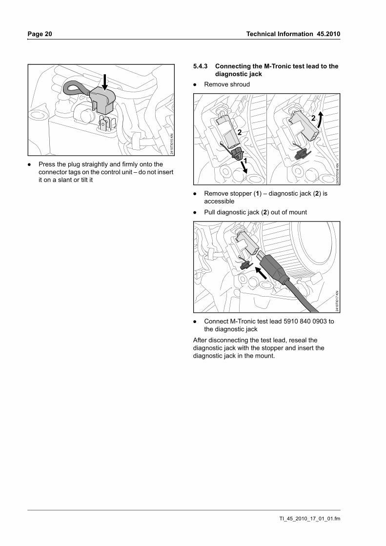
. Press the plug straightly and firmly onto the connector tags on the control unit – do not insert it on a slant or tilt it
5.4.3 Connecting the M-Tronic test lead to the diagnostic jack
. Remove shroud
. Remove stopper (1) – diagnostic jack (2) is accessible
. Pull diagnostic jack (2) out of mount
. Connect M-Tronic test lead 5910 840 0903 to the diagnostic jack
After disconnecting the test lead, reseal the diagnostic jack with the stopper and insert the diagnostic jack in the mount.
2410
TI01
5 KN
2
1
2410
TI01
6 KN
2
2410
TI01
7 KN
TI_45_2010_17_01_01.fm
Technical Information 45.2010 Page 21
5.4.4 Checking the solenoid valve
Measuring resistance. Set Master Control lever to position F
. Connect M-Tronic test lead 5910 840 0903 to the diagnostic jack
. Measure resistance between the plugs of the M-Tronic test lead
Target value: between 28 and 42 ohms
If the target value is not attained, check electrical leads for interruption, short to voltage and short to ground.
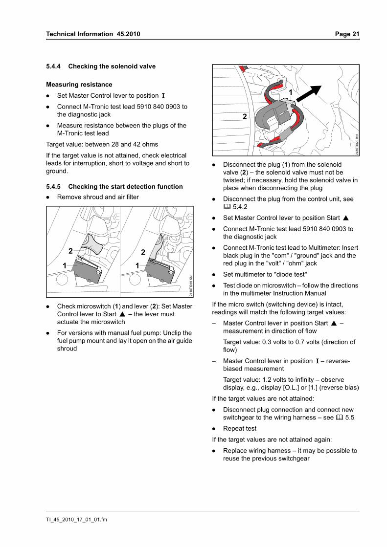
5.4.5 Checking the start detection function. Remove shroud and air filter
. Check microswitch (1) and lever (2): Set Master Control lever to Start } – the lever must actuate the microswitch
. For versions with manual fuel pump: Unclip the fuel pump mount and lay it open on the air guide shroud
. Disconnect the plug (1) from the solenoid valve (2) – the solenoid valve must not be twisted; if necessary, hold the solenoid valve in place when disconnecting the plug
. Disconnect the plug from the control unit, see b 5.4.2
. Set Master Control lever to position Start }
. Connect M-Tronic test lead 5910 840 0903 to the diagnostic jack
. Connect M-Tronic test lead to Multimeter: Insert black plug in the "com" / "ground" jack and the red plug in the "volt" / "ohm" jack
. Set multimeter to "diode test"
. Test diode on microswitch – follow the directions in the multimeter Instruction Manual
If the micro switch (switching device) is intact, readings will match the following target values:
– Master Control lever in position Start } – measurement in direction of flow
Target value: 0.3 volts to 0.7 volts (direction of flow)
– Master Control lever in position F – reverse-biased measurement
Target value: 1.2 volts to infinity – observe display, e.g., display [O.L.] or [1.] (reverse bias)
If the target values are not attained:
. Disconnect plug connection and connect new switchgear to the wiring harness – see b 5.5
. Repeat test
If the target values are not attained again:
. Replace wiring harness – it may be possible to reuse the previous switchgear
2410
TI01
9 KN
1
2 2
1
2
2410
TI02
0 KN
1
TI_45_2010_17_01_01.fm
Page 22 Technical Information 45.2010
5.4.6 Checking the wiring harness. Remove shroud and fan housing
. Set Master Control lever to position STOP 0
. Disconnect the plug from the control unit, see b 5.4.2
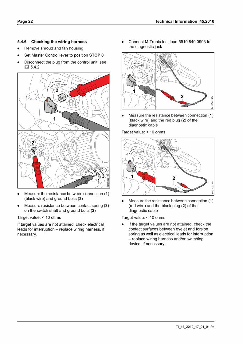
. Measure the resistance between connection (1) (black wire) and ground bolts (2)
. Measure resistance between contact spring (3) on the switch shaft and ground bolts (2)
Target value: < 10 ohms
If target values are not attained, check electrical leads for interruption – replace wiring harness, if necessary.
. Connect M-Tronic test lead 5910 840 0903 to the diagnostic jack
. Measure the resistance between connection (1) (black wire) and the red plug (2) of the diagnostic cable
Target value: < 10 ohms
. Measure the resistance between connection (1) (red wire) and the black plug (2) of the diagnostic cable
Target value: < 10 ohms. If the target values are not attained, check the
contact surfaces between eyelet and torsion spring as well as electrical leads for interruption – replace wiring harness and/or switching device, if necessary.
3
2410
TI02
8 K
N
2
2
1
1
2410
TI02
1 KN2
1
2410
TI02
2 KN
2
TI_45_2010_17_01_01.fm
Technical Information 45.2010 Page 23
5.5 Carburetor and switching device
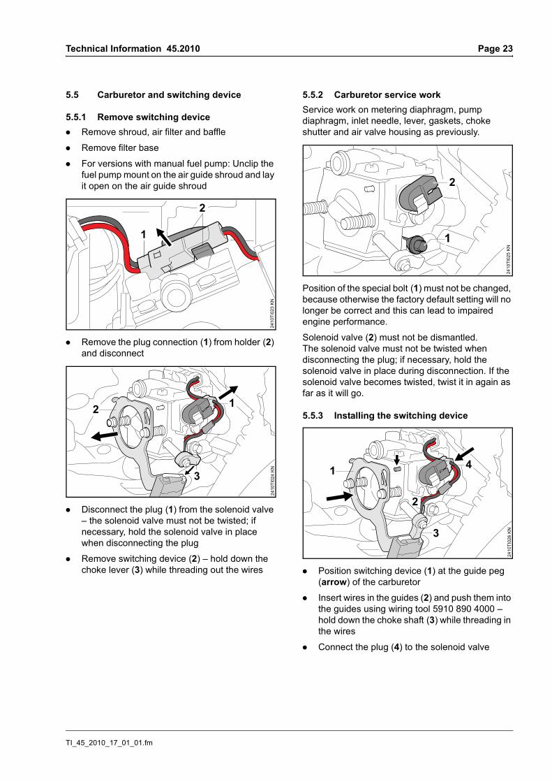
5.5.1 Remove switching device. Remove shroud, air filter and baffle
. Remove filter base
. For versions with manual fuel pump: Unclip the fuel pump mount on the air guide shroud and lay it open on the air guide shroud
. Remove the plug connection (1) from holder (2) and disconnect
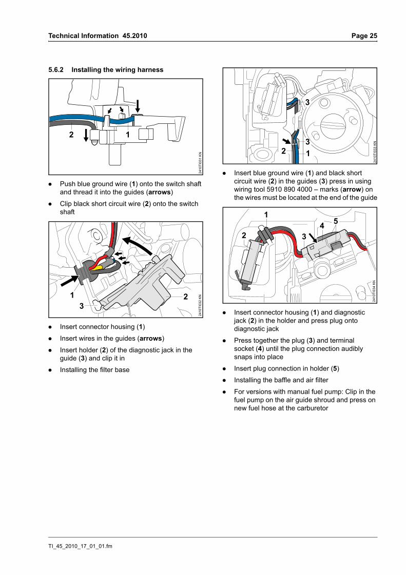
. Disconnect the plug (1) from the solenoid valve – the solenoid valve must not be twisted; if necessary, hold the solenoid valve in place when disconnecting the plug
. Remove switching device (2) – hold down the choke lever (3) while threading out the wires
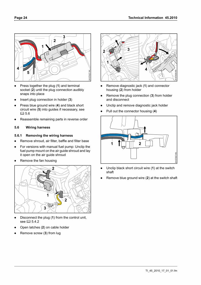
5.5.2 Carburetor service workService work on metering diaphragm, pump diaphragm, inlet needle, lever, gaskets, choke shutter and air valve housing as previously.
Position of the special bolt (1) must not be changed, because otherwise the factory default setting will no longer be correct and this can lead to impaired engine performance.
Solenoid valve (2) must not be dismantled. The solenoid valve must not be twisted when disconnecting the plug; if necessary, hold the solenoid valve in place during disconnection. If the solenoid valve becomes twisted, twist it in again as far as it will go.
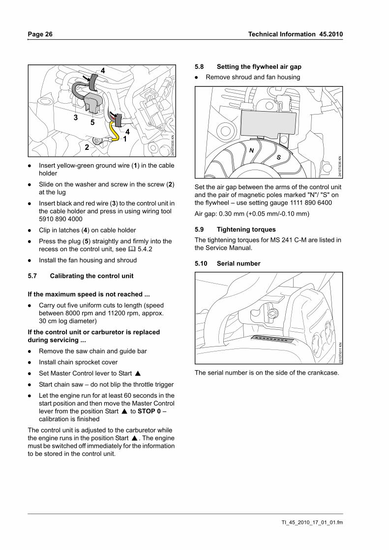
5.5.3 Installing the switching device
. Position switching device (1) at the guide peg (arrow) of the carburetor
. Insert wires in the guides (2) and push them into the guides using wiring tool 5910 890 4000 – hold down the choke shaft (3) while threading in the wires
. Connect the plug (4) to the solenoid valve
2
1
2410
TI02
3 KN
2410
TI02
4 KN
2 1
3
2
1
2410
TI02
5 KN
224
10TI
026
KN
1 4
3
TI_45_2010_17_01_01.fm
Page 24 Technical Information 45.2010
. Press together the plug (1) and terminal socket (2) until the plug connection audibly snaps into place
. Insert plug connection in holder (3)
. Press blue ground wire (4) and black short circuit wire (5) into guides if necessary, see b 5.6
. Reassemble remaining parts in reverse order
5.6 Wiring harness
5.6.1 Removing the wiring harness. Remove shroud, air filter, baffle and filter base
. For versions with manual fuel pump: Unclip the fuel pump mount on the air guide shroud and lay it open on the air guide shroud
. Remove the fan housing
. Disconnect the plug (1) from the control unit, see b 5.4.2
. Open latches (2) on cable holder
. Remove screw (3) from lug
. Remove diagnostic jack (1) and connector housing (2) from holder
. Remove the plug connection (3) from holder and disconnect
. Unclip and remove diagnostic jack holder
. Pull out the connector housing (4)
. Unclip black short circuit wire (1) at the switch shaft
. Remove blue ground wire (2) at the switch shaft
23
1
2410
TI02
7 KN5
4
2
2410
TI02
9 K
N
2
3
1
1
2
2410
TI03
0 KN
3
4
2410
TI03
7 KN
1 2
TI_45_2010_17_01_01.fm
Technical Information 45.2010 Page 25
5.6.2 Installing the wiring harness
. Push blue ground wire (1) onto the switch shaft and thread it into the guides (arrows)
. Clip black short circuit wire (2) onto the switch shaft
. Insert connector housing (1)
. Insert wires in the guides (arrows)
. Insert holder (2) of the diagnostic jack in the guide (3) and clip it in
. Installing the filter base
. Insert blue ground wire (1) and black short circuit wire (2) in the guides (3) press in using wiring tool 5910 890 4000 – marks (arrow) on the wires must be located at the end of the guide
. Insert connector housing (1) and diagnostic jack (2) in the holder and press plug onto diagnostic jack
. Press together the plug (3) and terminal socket (4) until the plug connection audibly snaps into place
. Insert plug connection in holder (5)
. Installing the baffle and air filter
. For versions with manual fuel pump: Clip in the fuel pump on the air guide shroud and press on new fuel hose at the carburetor
2410
TI03
1 KN
2 1
1
2410
TI03
2 KN2
3
3
3
2410
TI03
3 KN
12
543
2410
TI03
4 KN
1
2
TI_45_2010_17_01_01.fm
Page 26 Technical Information 45.2010
. Insert yellow-green ground wire (1) in the cable holder
. Slide on the washer and screw in the screw (2) at the lug
. Insert black and red wire (3) to the control unit in the cable holder and press in using wiring tool 5910 890 4000
. Clip in latches (4) on cable holder
. Press the plug (5) straightly and firmly into the recess on the control unit, see b 5.4.2
. Install the fan housing and shroud
5.7 Calibrating the control unit
If the maximum speed is not reached .... Carry out five uniform cuts to length (speed
between 8000 rpm and 11200 rpm, approx. 30 cm log diameter)
If the control unit or carburetor is replaced during servicing .... Remove the saw chain and guide bar
. Install chain sprocket cover
. Set Master Control lever to Start }
. Start chain saw – do not blip the throttle trigger
. Let the engine run for at least 60 seconds in the start position and then move the Master Control lever from the position Start } to STOP 0 – calibration is finished
The control unit is adjusted to the carburetor while the engine runs in the position Start }. The engine must be switched off immediately for the information to be stored in the control unit.
5.8 Setting the flywheel air gap. Remove shroud and fan housing
Set the air gap between the arms of the control unit and the pair of magnetic poles marked "N"/ "S" on the flywheel – use setting gauge 1111 890 6400
Air gap: 0.30 mm (+0.05 mm/-0.10 mm)
5.9 Tightening torquesThe tightening torques for MS 241 C-M are listed in the Service Manual.
5.10 Serial number
The serial number is on the side of the crankcase.
3
4
2410
TI03
5 K
N
4
2
5
1
2410
TI03
6 KN
2310
TI01
1 KN
TI_45_2010_17_01_01.fm
Technical Information 45.2010 Page 27
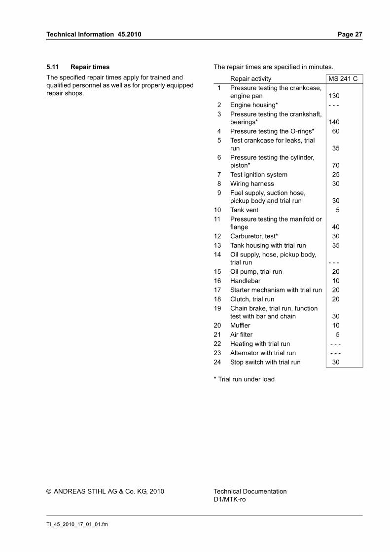
5.11 Repair timesThe specified repair times apply for trained and qualified personnel as well as for properly equipped repair shops.
Repair activity MS 241 C 1 Pressure testing the crankcase,
engine pan 130 2 Engine housing* - - - 3 Pressure testing the crankshaft,
bearings* 140 4 Pressure testing the O-rings* 60 5 Test crankcase for leaks, trial
run 35 6 Pressure testing the cylinder,
piston* 70 7 Test ignition system 25 8 Wiring harness 30 9 Fuel supply, suction hose,
pickup body and trial run 3010 Tank vent 511 Pressure testing the manifold or
flange 4012 Carburetor, test* 3013 Tank housing with trial run 3514 Oil supply, hose, pickup body,
trial run - - -15 Oil pump, trial run 2016 Handlebar 1017 Starter mechanism with trial run 2018 Clutch, trial run 2019 Chain brake, trial run, function
test with bar and chain 3020 Muffler 1021 Air filter 522 Heating with trial run - - -23 Alternator with trial run - - -24 Stop switch with trial run 30 * Trial run under load