ALSO PUBLISHED ONLINE: FEBRUARY2012 www.highfrequencyelectronics.com Ideas for today’s engineers: Analog · Digital · RF · Microwave · mm-wave · Lightwave INSIDE THIS ISSUE: Non-Resonant Slotted Waveguide Antenna Design Method Power Amps Resistive Products Oscillators Synthesizers N EW C OMPONENTS C ALL FOR A H ARDWARE C OMPARISON OF R ECEIVER A RCHITECTURES
Transcript
February 2012 1
ALSO PUBLISHED ONLINE: FEBRUARY2012www.highfrequencyelectronics.com
Ideas for today’s engineers: Analog · Digital · RF · Microwave · mm-wave · Lightwave
New Components Call for a Hardware Comparison of Receiver Architectures
By Todd Nelson, Signal Chain Module Development Manager, Linear Technology Corp.
2 High Frequency Electronics
The battle between superheterodyne radio architecture
and direct conversion (homodyne or zero-IF) radio architecture goes back to the 1930s. Each has its advantages for particular types of equip-
ment. Superheterodyne is popular in cellular base stations and direct conversion has prolif-erated in software-defined radio applications such as municipal radios. The simplicity of direct conversion hardware promises lower cost, lower power consumption and less board space than superheterodyne, which is attrac-tive to cellular service providers. Yet the hard-ware simplicity is offset by the software com-plexity to deal with inherent problems of DC offset. This article will probe the perceptions and realities of the hardware differences, exploring the easy path and simply ignoring the software issues.
The tsunami of data transmitted over cel-lular networks was brought on by tremendous advances in smart phones, tablets and other devices that access the Internet in these fre-quency bands. This has increased the technical requirements, while pressuring suppliers to reduce costs. Modern base stations take many forms—from traditional racks to smaller units operating on just a few Watts of power. The circuitry required to support multi-ple channels in tiny base station form factors assume a variety of approaches to integration. With recent developments, just how significant is the difference
between superheterodyne hardware and direct conversion hardware?
Review of the Basic ArchitecturesEdwin H. Armstrong invented the super-
heterodyne receiver architecture in 1918, by most accounts. In this common type of receiver, the radio frequency (RF) signal is mixed with a local oscillator (LO) signal to generate an inter-mediate frequency (IF) which is then demodu-lated. The LO frequency is offset from the RF carrier frequency, creating images of the signal. The IF signal is passed, while all other images are rejected by filtering. In modern receivers, the IF signal is converted to digital using an analog-to-digital converter (ADC) and then demodulated in the digital domain (see Figure 1).
The direct-conversion receiver was devel-oped a few years later as an alternative to the superheterodyne receiver. However, unlike the superheterodyne, the LO frequency is not offset from, but equal to the received signal’s fre-quency. The single mixer is replaced by two mixers, one fed with the RF and LO signals, and the other fed with the RF signal and a quadrature LO signal. The result is a demodu-lated output which is digitized by two ADC converters at baseband (see Figure 2). In other words, the intermediate frequency is zero. The filtering requirement is simplified because only
The simplicity of direct conversion hardware promises lower cost,
lower power consumption and less
board space than superheterodyne.
Figure 1 • Superheterodyne Receiver Architecture
3 High Frequency Electronics
High Frequency Design
Receiver Architectures
a lowpass filter is required – unlike the superheterodyne with its bandpass filter.
Evolution of HardwareRegardless of the architecture, there have been steady
improvements over the decades. The performance of inte-grated circuit (IC) components continues to improve while at the same time consuming less power and requiring less printed circuit board (PCB) area. ADC resolution and sample rates have improved to allow wider bandwidth signals and higher input frequencies.
An early attraction of the direct conversion receiver was the single frequency conversion to baseband. In past decades, the superheterodyne receiver used multiple fre-quency downconversion stages. Gradually, as mixer and filter technology improved, stages were consolidated to the point where a typical superheterodyne receiver has only one frequency conversion stage in analog and one digital downconversion stage implemented in a digital signal pro-cessor.
Another attraction of the direct conversion architecture is lowpass filtering. The superheterodyne architecture requires a bandpass filter at the IF. In many cases, the bandpass filter is of a high order or of a surface acoustic wave (SAW) type. SAW filters require a hermetic package and are often quite large and expensive. While there have been tremendous improvements in SAW filter technology and packaging, the lowpass filter is still considered to be more attractive.
Latest Hardware ComparisonTo attempt a reasonable comparison of cost, power and
board space, it is necessary to collect the components nec-essary to implement four receiver channels for a small base station suitable for 20MHz signal bandwidth. Each superheterodyne receiver uses a single mixer, a variable gain amplifier, a SAW filter, a second IF amplifier stage and a high-speed ADC. Each direct conversion receiver uses an I/Q demodulator, two baseband amplifiers and two high-speed ADCs. An example board layout is used to compare the estimated board space required for these com-ponents and the nominal power consumption is simply
calculated from data sheet parameters. The expectation is that the direct conversion architecture will prove to be significantly better in both respects.
Superheterodyne ExampleFor four channels of superheterodyne, there are com-
monly available dual mixers in QFN packages of 5mm x 5mm – so two duals are required. With integrated balun transformers and internal matching components for the RF and LO inputs, the number of passive components is minimal and mostly available in 0201 and 0402 sizes – these shall be ignored in this comparison since they are also required for direct conversion. Similarly, there are dual digital VGAs available in suitable frequency ranges. Such dual VGAs are also available in 5mm x 5mm QFN packages—again, two are required to implement four channels. A bit of filtering may be required following the mixer stages, so a few 0402 inductors and 0201 capacitors are in order. To achieve the required selectivity, a SAW bandpass filter is required for superheterodyne receivers. A separate SAW filter is required for each of the four chan-nels. At RF frequencies, SAW filters can be quite small. In the common IF range from 70MHz to 192MHz, SAW filters can be found in 5mm x 7mm packages. The SAW filter will require a few impedance matching components even if the output of the preceding VGA and input of the following amplifier are 50 ohms. Normally, another gain stage is required to make up for the insertion loss of the filter.
However, a new quad ADC with integrated amplifiers is offered in a System in Package (SiP), the LTM9012-AB µModule® ADC from Linear Technology. At 15mm x 11.25mm, it is smaller than the equivalent quad ADC with four differential amplifiers and the associated bypass capacitors and anti-alias filter components. With 20dB of gain, the LTM9012 achieves 68.5dB signal to noise ratio (SNR) and 79dB spurious-free dynamic range (SFDR). The amplifiers and the filtering within the LTM9012-AB limit the input frequency to about 90MHz. Therefore, a 70MHz IF is suitable, but not the higher IFs often implemented with superheterodyne receivers in base station applica-tions. Nonetheless, this offers the most compact imple-mentation.
The LTM9012 represents a different approach to inte-gration. The µModule or SiP packaging allows separate die to be assembled along with various passive components on a laminate substrate, and molded such that it looks like a regular ball grid array (BGA) integrated circuit (IC). In this case the ADC is optimized for low power and good AC performance using a small-geometry CMOS process. The amplifiers use a silicon-germanium (SiGe) process in order to maximize their performance. These are traditional dif-ferential amplifiers, so the gain is set with resistors at 10V/V or 20dB. A true op amp input simplifies the match-ing by isolating the high frequency sampling glitches from the signal path and also allows for single-ended signals to
3 High Frequency Electronics
Figure 2 • Direct Conversion Receiver Architecture
4 High Frequency Electronics
WiFi PA REQUIREMENTSHigh Frequency Design
mate up with the differential ADC inputs internally. Most monolithic ADCs with buffered front-ends provide no gain at all, are still differential and only offer the isolation of the glitches. Equally beneficial is the anti-alias filtering that limits wideband amplifier noise. In terms of overall board space, since all of the reference and supply bypass capaci-tors are inside the package, the overall system design can be packed very tightly without compromising performance. Such compromises often occur when reference and supply bypass capacitors are too far from or near digital signals which can then corrupt the data conversion process. Finally, the substrate allows the pin assignments to flow logically: analog inputs on one side, digital outputs on the other side of the package.
In this example, the number of active components is five, with four SAW filters and 80 other small passive com-ponents (see Figure 3). The overall area is about 43 mm x 21 mm = 903 mm2; however not all of that area is utilized, so the effective area is more like 700 mm2. Of course, this is on one side of the board and company-specific design rules may allow for an even more compact layout. For power calculations, this example uses the LT5569 as the dual mixer, the AD8376 as the dual VGA and the LTM9012-AB as the combination of the second amplifier stages and quad ADC. The mixer is an active type, which operates over a wide 300MHz to 4GHz frequency range, so a single part can be configured to operate on any of the cellular bands from 700MHz to 2.7GHz. With best-in-class power consumption, it also has robust inputs that can withstand strong in-band blocking interference signals without sig-nificantly degrading its noise figure. The overall power
consumption of the four channel system is 4.9 Watts, not including possible power dissipated in resistive dividers.
Direct Conversion ExampleFor four direct conversion channels our only options
are individual I/Q demodulators, so four of those in 5mm x 5mm QFN packages are required. Some, like the LT5575, have integrated RF and LO baluns to minimize the num-ber of external components. A bit of filtering is beneficial, and of course some small bypass capacitors. For the low-pass filter, multiple L-C and R-C sections are done. For the gain stage, the LTM9012-AB is again appropriate. As a quad, it only supports two direct conversion channels, so a second one is needed.
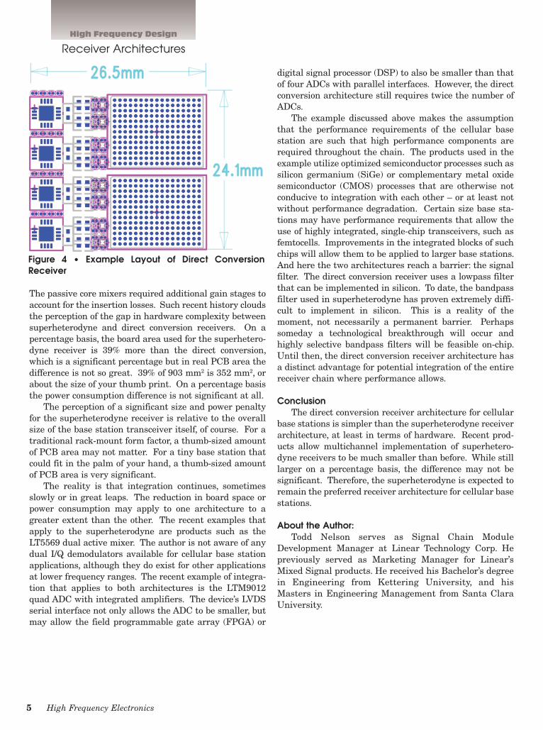
In this example, the number of active components is 6 with 84 small passive components (see Figure 4). The overall area is about 27 mm x 24 mm = 648 mm2. For power calculations this example uses the LT5575 I/Q demodulator and two of the LTM9012-AB. The overall power consumption of the four channels is 5.1 Watts, not including possible power dissipated in resistive dividers. However, the ADC is sampling at 125Msps, which is com-mon but likely more than is necessary for 10MHz. At 65Msps, the same function could be done with much less power consumption in the ADC. Recalculating the power consumption brings the new total to 4.6 Watts.
Perception and RealityNot too many years ago, a superheterodyne receiver
used multiple mixers and multiple SAW filters per chan-nel. And SAW filters in the day could be 25mm x 9mm.
Receiver Architectures
Figure 3 • Example Layout of Superheterodyne Receiver
5 High Frequency Electronics
WiFi PA REQUIREMENTSHigh Frequency Design
The passive core mixers required additional gain stages to account for the insertion losses. Such recent history clouds the perception of the gap in hardware complexity between superheterodyne and direct conversion receivers. On a percentage basis, the board area used for the superhetero-dyne receiver is 39% more than the direct conversion, which is a significant percentage but in real PCB area the difference is not so great. 39% of 903 mm2 is 352 mm2, or about the size of your thumb print. On a percentage basis the power consumption difference is not significant at all.
The perception of a significant size and power penalty for the superheterodyne receiver is relative to the overall size of the base station transceiver itself, of course. For a traditional rack-mount form factor, a thumb-sized amount of PCB area may not matter. For a tiny base station that could fit in the palm of your hand, a thumb-sized amount of PCB area is very significant.
The reality is that integration continues, sometimes slowly or in great leaps. The reduction in board space or power consumption may apply to one architecture to a greater extent than the other. The recent examples that apply to the superheterodyne are products such as the LT5569 dual active mixer. The author is not aware of any dual I/Q demodulators available for cellular base station applications, although they do exist for other applications at lower frequency ranges. The recent example of integra-tion that applies to both architectures is the LTM9012 quad ADC with integrated amplifiers. The device’s LVDS serial interface not only allows the ADC to be smaller, but may allow the field programmable gate array (FPGA) or
digital signal processor (DSP) to also be smaller than that of four ADCs with parallel interfaces. However, the direct conversion architecture still requires twice the number of ADCs.
The example discussed above makes the assumption that the performance requirements of the cellular base station are such that high performance components are required throughout the chain. The products used in the example utilize optimized semiconductor processes such as silicon germanium (SiGe) or complementary metal oxide semiconductor (CMOS) processes that are otherwise not conducive to integration with each other – or at least not without performance degradation. Certain size base sta-tions may have performance requirements that allow the use of highly integrated, single-chip transceivers, such as femtocells. Improvements in the integrated blocks of such chips will allow them to be applied to larger base stations. And here the two architectures reach a barrier: the signal filter. The direct conversion receiver uses a lowpass filter that can be implemented in silicon. To date, the bandpass filter used in superheterodyne has proven extremely diffi-cult to implement in silicon. This is a reality of the moment, not necessarily a permanent barrier. Perhaps someday a technological breakthrough will occur and highly selective bandpass filters will be feasible on-chip. Until then, the direct conversion receiver architecture has a distinct advantage for potential integration of the entire receiver chain where performance allows.
ConclusionThe direct conversion receiver architecture for cellular
base stations is simpler than the superheterodyne receiver architecture, at least in terms of hardware. Recent prod-ucts allow multichannel implementation of superhetero-dyne receivers to be much smaller than before. While still larger on a percentage basis, the difference may not be significant. Therefore, the superheterodyne is expected to remain the preferred receiver architecture for cellular base stations.
About the Author:Todd Nelson serves as Signal Chain Module
Development Manager at Linear Technology Corp. He previously served as Marketing Manager for Linear’s Mixed Signal products. He received his Bachelor’s degree in Engineering from Kettering University, and his Masters in Engineering Management from Santa Clara University.
Receiver Architectures
Figure 4 • Example Layout of Direct Conversion Receiver