Page 1
New Design Approach for RC Slender Columns
Prof. Dr. Hamdy Elgohary
Professor of Reinforced Concrete Structures,
Faculty of Engineering, Mansoura University, Egypt
Email: [email protected]
Abstract
The recommended design methods for RC slender columns in the most current Codes and recent
researches are mainly based on the moment magnifier approach. In these methods, the linear static
moment acting on column section is increased by an empirical factor. This factor takes into account the
slenderness ratio and end conditions of the column. Both geometric and physical nonlinear behaviors are
not considered in most of the current Codes. Ignoring of the nonlinear behavior leads to inaccurate design
output.
In the present paper a critical review will be carried out for most of the recommended design methods in
Codes and recent researches. Results of these methods will also be compared with experimental results.
On the bases of this study a new simple and direct design approach will be recommended for the design
of RC slender columns considering both geometric and material nonlinearity.
Keywords: Slender columns, eccentric compression, nonlinear analysis
Page 2
1. Introduction
Columns are structural elements used primarily to support compressive loads. A short column is one in
which the ultimate load at a given eccentricity is governed only by the strength of the materials and the
dimensions of the cross-section. A slender column is one in which the ultimate load is governed not only
by the strength of the materials and the dimensions of the cross section but also by the slenderness, which
produces additional bending moment due to lateral deformations. For eccentrically loaded short columns,
the column behavior will follow the linear path until intersect the interaction diagram. For eccentrically
loaded slender columns, the column will follow a non-linear path until intersects the interaction diagram.
This means that, due to the non-linear effects the actual moment on the column is greater than the linear
moment.
In designing eccentrically loaded slender columns, the second-order effects are very important
parameters. Both geometric and physical (material) nonlinearities are important factor in the analysis of
eccentrically loaded reinforced concrete slender column. Beside the current Codes’ methods, several
empirical formulae for designing reinforced concrete slender columns are available in the literature. To
evaluate the efficiency and accuracy of the current Codes’ methods and these empirical formulae a
comparison study between their results and the experimental results will be carried out. Based on the
results of this comparison and the experimental results carried out previously [2 & 5], new equations will
be developed to be used for the design of reinforced concrete slender columns. In these new equations the
effect of both geometric and physical nonlinearity will be considered.
2. Slender Columns Behaviour
The slenderness of a column may result in the ultimate load being reduced by lateral deflections of the
column caused by bending. This effect is illustrated in Fig. 1 for a particular case of an initially straight
column with bending in single curvature caused by load P applied with equal eccentricity e at both ends.
The bending deformation of the column causes the eccentricity of the load at the critical section to
become (e + Δ), where Δ is the additional eccentricity due to lateral deflection at that section. Hence, the
maximum moment increases to P (e + Δ). This is commonly referred to as the P-Δ effect. A short column
is defined as one in which the ultimate load is not reduced by the bending deformations because the
additional eccentricities Δ are negligible. A slender column is defined as one in which the ultimate load is
reduced by the amplified bending moment caused by additional eccentricity.
Page 3
P
P
e
Fig. 1: Eccentrically loaded slender column.
The behavior of the column shown in Fig. 2 under increasing load is illustrated on the interaction diagram
for the critical section of the column given in Fig. 1. If the additional eccentricity Δ is negligible, the
maximum moment M will equal P.e at all stages and a linear P-M path will be followed with increasing
load. This is a short column behavior, and material failure of the section will occur when the interaction
line is reached. If the column is slender, the maximum moment M will equal P (e + Δ), and because Δ
increases more rapidly at high load levels, the P-M path will be curved. Two types of slender column
behavior may occur. First, a column may be stable at lateral deflection Δ1 but having reached the
interaction line a material failure of the section occurs. This type of failure generally occurs in practical
columns of buildings that are braced against sway. Second, if the column is very slender it may become
unstable before reaching the interaction line. This instability failure may occur in unbraced columns.
P
M
P e P 1
P e P 2
Short column, material failure
Slender column,material failure
Slender column,instability failure
Fig. 2: Interaction diagram for a column section illustrating short and slender column P-M behavior
up to failure.
Page 4
3. Evaluation Models
An evaluation study for the Codes’ formulae and the empirical methods’ formulae will be carried to
assess its accuracy. A group of columns, from different experimental tests available in the literature, is
selected for the evaluation study. Twelve models are selected from tests carried out by Christina, C., and
Kent, G. [2]. The models consist of 12 slender columns, with concrete characteristic compressive
strengths of 330, 370, 430, 860, 910, and 930 kg/cm2. The lengths of the models are 2.4, 3.0, and 4.0 m,
with square cross-section and slenderness ratios 15 and 20. The thickness of the concrete cover measured
to the outer edge of the stirrups is 15 mm for all of the models. The parameters varied in the models are
concrete strength, the stirrups spacing, and the slenderness ratio. These models are named “C1” to “C12”.
Fifteen models are selected from tests carried out by El-Gohary, H. A. [5]. The models are 10x20 cm
cross-section and have different heights to obtain different slenderness ratios. The used heights are 2.5,
3.0, and 3.5 m, with slenderness ratios 25, 30, and 35 respectively. The longitudinal reinforcement is four
bars with 10 mm diameter. Rectangular lateral ties of 6 mm diameter at each 10 cm of column height are
used. The lateral ties are spaced at 5 cm at both ends of each model for a distance of 25 cm and then
spaced at 10 cm. The concrete compressive strengths are 265, 430, and 580 kg/cm2. These models are
named “C13” to “C27”.
4. Current Codes Results
The evaluation models have been analyzed by using Eurocode2 [6], Egyptian code (ECCS 203-2007) [4] ,
ACI 318-99 [1] and Russian code (SNIP 2.03.01-84) [11]. The obtained results are shown in Fig. 3 (total
lateral deflection) and Fig. 4 (effective flexural rigidity). From these two Figures it can be concluded that:
Comparison of the results obtained by Eurocode2 (1992) with test results shows that the mean of the ratio
of the flexural rigidity ( EI cal/ EI exp) is 0.698 with 0.127 standard deviations, while the mean of the
deflection ratio (Δcal/Δexp) is 1.535 with 0.583 standard deviations. Eurocode2 (1992) over-estimates the
total deflection, and under-estimates the flexural rigidity.
In case of the Egyptian code (ECCS 203-2007) the mean of the deflection ratio is 1.395 with 0.469
standard deviations and the mean of the ratio of the flexural rigidity is 0.905 with 0.149 standard
deviations. Egyptian code (ECCS 203-2007) method under-estimates the flexural rigidity while over-
estimates the total deflection.
ACI 318-99 results show that the mean of the deflection ratio is 1.282 with 1.665 standard deviations and
he mean of the ratio of the flexural rigidity is 0.620 with 0.208 standard deviations i.e., ACI 318-99 over-
estimates the deflection while it under-estimates the flexural rigidity.
Russian code (SNIP 2.03.01-84) results give a mean of the flexural rigidity ratio 2.628 with 1.112
standard deviations and the mean of the deflection ratio is 0.731 with 0.145 standard deviations. Russian
code (SNIP 2.03.01-84) under-estimates the deflection and over-estimates the flexural rigidity.
The results obtained using the Egyptian code method for the flexural rigidity can be considered good
among all other results of the all considered Codes.
Page 5
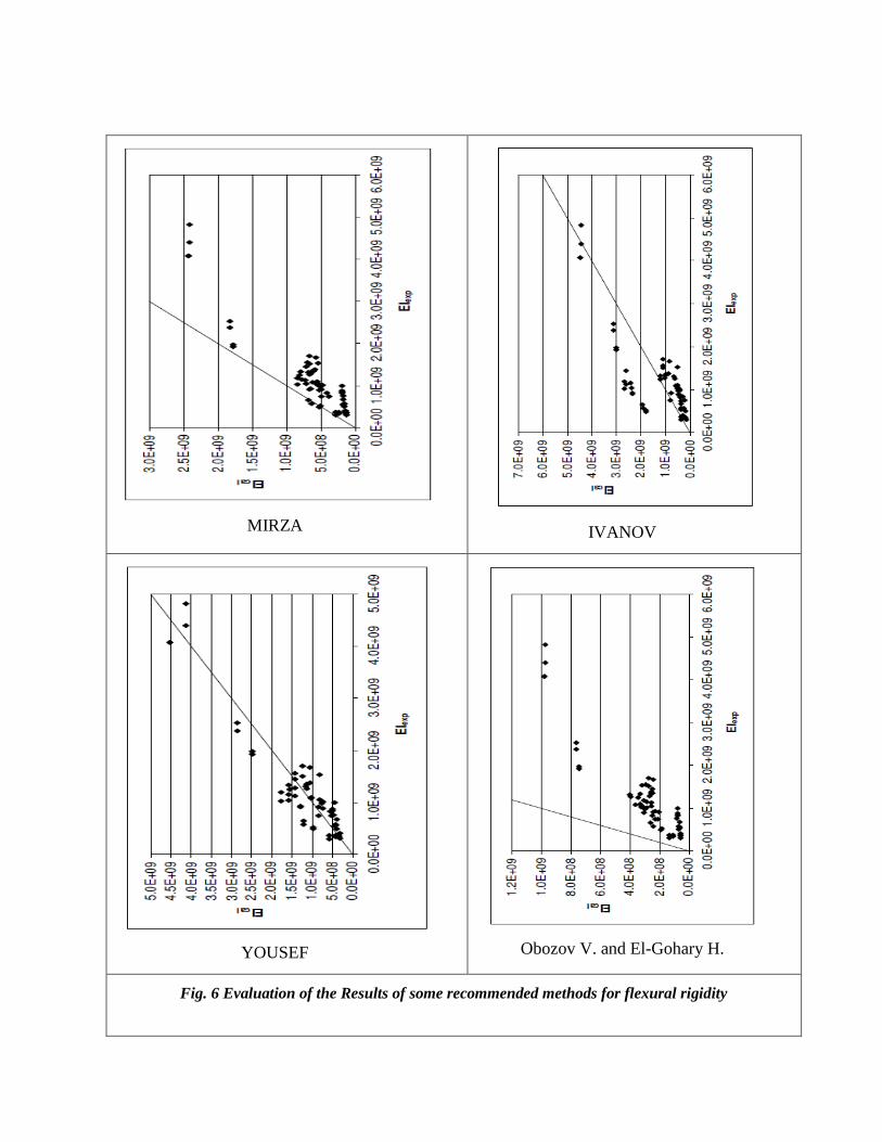
5. Results of Some Recommended Methods
The evaluation models have been analyzed by using recommended methods for the lateral deflection and
the effective flexural rigidity by Mirza A. (1990) [9], Ivanov A. (2004) [7], Youssef K. I. (2005) [13] and
Obozov V. I. and El-Gohary H. A. (2007) [10]. The obtained results are shown in Fig. 5 (total lateral
deflection) and Fig. 6 (effective flexural rigidity). From these two Figures it can be concluded that:
The results obtained by the recommended equations by Mirza A., show that the mean of the deflection
ratio is 1.253 with 1.370 standard deviations and the mean of the ratio of the flexural rigidity is 0.576
with 0.215 standard deviations. Mirza A. formulae over-estimate the deflection and under-estimate the
flexural rigidity.
The use of the recommended method by Ivanov A. (2004) gives mean value of the deflection 0.945 with
0.711 standard deviations and mean value of the ratio of the flexural rigidity 1.090 with 0.845 standard
deviations. The formulae developed by Ivanov A. under-estimate the deflection and over-estimate the
flexural rigidity
Youssef K. I. (2005) method gives mean value of the deflection ratio 1.156 with 1.112 standard
deviations and mean of the ratio of the flexural rigidity 1.047 with 0.385 standard deviations. The
formulae developed by Youssef K. I. over-estimate the total deflection and the flexural rigidity.
The mean of the deflection obtained from the formula developed by Obozov V. and El-Gohary H., is
2.261 with 4.642 standard deviations, while the mean of the ratio of the flexural rigidity is 0.241 with
0.092 standard deviations. The formulae developed by Obozov V. and El-Gohary H. over-estimate the
deflection while it under-estimate the flexural rigidity.
As a result of this comparison review, the results obtained using the methods recommended by Ivanov A.
(2004) and Youssef K. I. (2005) show good agreement with the experimental results.
Page 6
(Eurocode2-1992)
(ECCS 203-2007)
(ACI 318-99)
(SNIP 2.03.01-84)
Fig. 3 Evaluation of Current Codes Results for total deflection
Page 7
(Eurocode2-1992)
(ECCS 203-2007)
(ACI 318-99)
(SNIP 2.03.01-84)
Fig. 4 Evaluation of Current Codes Results for flexural rigidity
Page 8
MIRZA
IVANOV
YOUSEF
Obozov V. and El-Gohary H.
Fig. 5 Evaluation of the Results of some recommended methods for total deflection
Page 9
MIRZA
IVANOV
YOUSEF
Obozov V. and El-Gohary H.
Fig. 6 Evaluation of the Results of some recommended methods for flexural rigidity
Page 10
6. Geometric Nonlinearity
In this section an equation for the lateral deflection of the slender reinforced concrete columns under
eccentric compression taking into account geometric nonlinearity will be developed. The physical
nonlinearity will be considered by the parameter Pc - critical load of the column:
2
2
L
EIPc
(1)
Where EI – effective flexural rigidity of the column
The lateral deflection at the mid-height of the slender column shown in Fig. 1 (case of slender column
under eccentric compression with equal end eccentricities and single curvature) has the form:
0
2
18
eP
P
c
(2)
Where e0 - eccentricity of the applied load P
In this case, the expression for the bending moment in the section at the mid-height will take the form:
)( 101 ePM (3)
Considering that the lateral deflection has sinusoidal profile, by using (3) and by integrating, the final
deflection will have the form:
...60sin8
60sin8
60sin88
0
3
42
0
2
32
0
22
0
2
e
P
Pe
P
Pe
P
Pe
P
P
cccc
f
(4)
After simplifications, the following formula will be obtained:
02
2
60sin8
1
8e
P
P
c
f
(5)
or
0
068.11
234.1e
P
P
c
f
(6)
Equation (6) gives the value of the lateral deflection of the eccentrically loaded slender reinforced
concrete columns taking into account geometric nonlinearity effect. The recommended formula in the
American and Russian Codes takes the form [1, 11]:
Page 11
0
1
1e
P
P
c
f
(7)
A comparison between the results of equation (6) and equation (7) is shown in Table 1 and in Fig. 7. This
comparison shows that due to the consideration of geometric nonlinearity effect, equation (6) gives a
larger value for the lateral deflection than that obtained by equation (7). Table 1 shows that the
consideration of geometric nonlinearity results in an increase in the total lateral deflection of 33 % in the
case of P/Pc = 0.5; 70 % in the case of P/Pc = 0.8 and 218 % in the case of P/Pc = 0.9.
Table 1 Comparison of the results obtained from equation (6) and equation (7)
cPP / 0.1 0.2 0.3 0.4 0.5 0.6 0.7 0.8 0.9
Eq. 6 1.38 1.57 1.82 2.15 2.65 3.44 4.89 8.48 31.80
Eq. 7 1.11 1.25 1.43 1.67 2.00 2.50 3.33 5.00 10.00
Eq. 7/Eq. 6 1.24 1.26 1.27 1.29 1.33 1.38 1.47 1.70 3.18
Fig. 7 Total lateral deflection with the consideration of geometric nonlinearity
To generalize equation (6) the case of slender column under eccentric compression with unequal end
eccentricities has been studied using the procedure recommended in [12] and following the same previous
steps, the nonlinear total lateral deflection in this case will have the form:
Page 12
021
068.11
601.0633.0e
P
P
ee
c
f
(8)
Where e2 is the smaller eccentricity
For the case of slender column under eccentric compression with one end eccentricities (e2 = 0) equation
(8) will be in the following form:
01
068.11
633.0e
P
P
e
c
f
(9)
The recommended equations (6), (8) and (9) can be used to determine the total lateral deflection for the
slender reinforced concrete columns with single curvature with the consideration of the geometric
nonlinearity.
Equation (6) has been applied to the evaluation experimental models. The obtained results are shown in
Fig. 8. The use of Equation (6) gives a mean value of the deflection ratio 1.034 with 0.23 standard
deviations.
Fig. 8 The ratio of the proposed to the experimental total lateral deflection
Page 13
7. Effective Flexural Rigidity
Using the evaluation test models in [3] and [5] and applying the multiple regression analysis technique [2
& 8] the equivalent flexural rigidity taking into account the effect of the material and nonlinearity can be
assumed to have the following form:
sscc IEIEch
ebaEI
(10)
where )/( he
is the initial eccentricity-depth ratio, is the slenderness ratio, cE is the concrete
elastic modulus, sE is the steel elastic modulus, cI
is the moment of inertia of the concrete section
about centroidal axis, sI is the moment of inertia of the reinforcement about centroidal axis of the
column cross-section and a, b and c are constants. Solving for the constants by the multiple regression
analysis technique the effective flexural rigidity will have the form:
sscc IEIEh
eEI
023.014.025.0 (11)
The evaluation models have been analyzed by using recommended equation (11) for the effective flexural
rigidity. The obtained results are shown in Fig. 9. The results obtained from recommended equation give
a mean of the flexural rigidity ratio 1.001, with 0.0813 standard deviation.
Fig. 9 The ratio of the proposed to the experimental effective flexural rigidity
Page 14
8. Recommended Approach
The recommended design approach for RC slender columns under eccentric compression considering
both the material and geometric nonlinearities can be summarized as follows:
1. Applying equation (11) to obtain the effective flexural rigidity (material nonlinearity)
2. Applying equation (1) to obtain the critical load Pc
3. Applying equation (6) to obtain the moment magnifier factor considering the geometric
nonlinearity
4. Applying the final magnified moment and the design load to the interaction diagram
9. Conclusion
The evaluation review of the current Codes’ formulae and some recommended empirical approaches for
the design of RC slender columns, shows that most of these methods under-estimate and/or over-estimate
the lateral deflection and/or the effective flexural rigidity. Based on this evaluation and considering the
evaluation experimental results new formulae for the total lateral deflection calculation and effective
flexural rigidity are recommended. In these formulae the effect of geometric nonlinearity and the material
nonlinearity have been taken into consideration. The results obtained using the recommended equations
show good agreement with the evaluation experimental results.
References
ACI (1999). Building code requirements for structural concrete, ACI 318-99 and commentary 318R-99,
American Concrete Institute, Framington Hills, Mich..
Carnahan, B., Luther, H. A., and Wilkes J. O. (1969). “Applied numerical methods”, John Willey & Sons,
Inc.
Christina, C. and Kent, G. (2000) “ Slender concrete columns subjected to sustained and short-term
eccentric loading“ ACI Structural Journal, Vol. 97, No. 1, pp. 233-240.
Egyptian code of practice for designing and construction of reinforced concrete structures, (2007).
El-Gohary, H. (2005) “Test on slender concrete columns under eccentric compression“ Eleventh
International Colloquium on Structural and Geotechnical Engineering, Faculty of Engineering, Ain
Shams University, Cairo, Egypt, 17-19 May.
European committee for standardization (1992) : Design of concrete structures-Part I: general rules and
rules for buildings (Eurocode 2).
Ivanov, A. (2004) “Special features for the design of slender columns in monolithic multistory buildings
with the consideration of longitudinal bending“ Journal of concrete and reinforced concrete, VOL 5, pp
27-29.
Mathews, J. H., (1992). “Numerical methods for mathematics, science, and engineering”, prentice - Hall
International, Inc.
Page 15
Mirza, A. & Lacroix, A. (2002) “Comparative study of strength-computation methods for rectangular
reinforced concrete columns“ ACI Structural Journal, Vol. 99, No. 4, pp. 399-410.
Obozov, V. I. and El-Gohary, H. (2007) “Non-linear deflection of RC slender columns under eccentric
compression“ Journal of earthquake engineering, safety of structures, Vol. 2, CNIISK, Moscow (In
Russian).
SNIP 2.03.01-84, (1989) Russian Code for "Concrete and Reinforced Concrete Structures", Moscow.
Timoshenko, S. P. & Gere, J. M. (1985) : Theory of Elastic Stability, McGraw-Hill, 17th Edition.
Youssef, K. (2005) “Prediction of second order effects in sway and non-sway reinforced concrete frames“
Ph.D. Thesis, Faculty of Engineering, Cairo University.