ELCAD 7 New Features of ELCAD/AUCOPLAN 7.12.0 February 2017 AUCOTEC AG Oldenburger Allee 24 D-30659 Hannover Phone: +49 (0)511 61 03-0 Fax: +49 (0)511 61 40 74 www.aucotec.com AUCOTEC, INC. 17177 North Laurel Park Drive, Suite 437 Livonia, MI 48152 Phone: +1 630 485 5600 Fax: +1 248 655 7800
Transcript
ELCAD 7
New Features of ELCAD/AUCOPLAN 7.12.0 February 2017
Copyright: All rights, especially the right of reproduction and distribution as well as translation, are reserved. No part of this book may be reproduced, stored in retrieval sys-tem, or transmitted in any form or by any means, electronic, mechanical, photocopying, microfilming, recording, or otherwise, without prior permission from AUCOTEC AG.
Exclusion of liability: Texts and software have been prepared with the greatest of care. The publishers as well as the authors cannot assume any legal or other liability of any nature for potential faulty statements and their consequences, which shall apply also for the software potentially included.
Trademarks: AUCOPLAN® and ELCAD® are registered trademarks of the AUCOTEC AG, Germany. MS-DOS® and Windows® are registered trademarks of the Microsoft Corpora-tion, USA.
Content
Content
1 New Features of ELCAD/AUCOPLAN Version 7.12.0 ............... 1
1.1 General Innovations ............................................................................. 2
1.1.1 ELCAD/AUCOPLAN now as MSI-Setup ..................................................... 2
1.1.2 Extended Information in the Project Properties ........................................ 2
1.2 New in Project Editing .......................................................................... 3
1.2.1 Processes as Central Means of Automation .............................................. 3
1.2.2 Reconstructing an Re-Evaluating a Project .............................................. 4
1.3 New in Drawing Editing ........................................................................ 5
1.3.1 Permanent Display of the Marking Arrows ............................................... 5
1.3.2 Replacing Symbol Texts and Free Texts in the Drawing Tree ..................... 6
1.3.3 Navigating via Core Symbols ................................................................. 6
1.3.4 Representation Filter when Copying from Template Projects ...................... 6
1.3.5 New Dialog when Outputting Revisions ................................................... 7
1.3.6 Changing the Properties of Symbol Texts ................................................ 7
1.4 New in Symbol Editing .......................................................................... 8
1.4.1 Integration of Bar Codes, QR Codes and other referenced Graphics into ELCAD ................................................................................................ 8
1.5 New Features of the Item Editor ......................................................... 14
1.5.1 Editing Symbols from the Item Editor ................................................... 14
1.5.2 Editing Terminal Diagrams from the Item Editor .................................... 14
1.6 New in List Editing .............................................................................. 15
1.6.1 New Status List Working Status ........................................................... 15
1.6.2 Extended Status List for Revisions ........................................................ 16
1.7 New in the Terminal Block Designer ................................................... 16
1.7.1 New Numbering Method "Sort According to Same Level" ......................... 16
1.7.2 Inserting a New, Single Terminal ......................................................... 17
1.8 New in Cable Editing ........................................................................... 17
1.8.1 Editing Cable Lists and Cable Assignment Lists ...................................... 17
1.9 New in Batch Processing ..................................................................... 18
1.9.1 Importing a Batch from Other Projects ................................................. 18
1.10 New in ELCADmaintenance ................................................................. 18
1.10.1 List View in ELCADmaintenance Available as Read-Only .......................... 18
1.11.1 New in the Generating Interface (EDM/PDM) ......................................... 19
1.11.2 Extended Output of Compact PDF in the Generating Interface (EDM/PDM) 19
i
Content
1.11.3 New in the DOCware Interface ............................................................. 19
1.11.4 Update of the Interface to the Phoenix Contact Clip Project ..................... 19
ii
New Features of ELCAD/AUCOPLAN Version 7.12.0
1 New Features of ELCAD/AUCOPLAN Version 7.12.0
When developing the version 7.12.0, our focus was among other things to "round off" the merging of batches and reports to reusable "processes" by taking into account your sug-gestions. For this purpose additional functions were made available, and the handling of processes and batches was consistently facilitated.
Thus you can automate your company-specific processes even more quickly and flexibly.
Over and above that, we have again meticulously analyzed your requirements and wishes and used them to filter many new features of version 7.12.0. With the current version, operating steps become still more efficient, and the access to the relevant objects and data becomes even easier.
As always, the main focus of all extensions is the compatibility of your data and easier handling.
Hannover, February 2017
- 1 -
New Features of ELCAD/AUCOPLAN Version 7.12.0
1.1 General Innovations
1.1.1 ELCAD/AUCOPLAN now as MSI-Setup For a number of years now, many users had uttered the wish to get the ELCAD/AUCOPLAN setup as MSI setup. In this way the installation and distribution of the software can be executed in a standardized way according to the requirements of the companies and the IT administration.
ELCAD/AUCOPLAN 7.12 is now available as MSI setup. More detailed information about the company-specific adaptation of the installation is available in a separate documenta-tion.
1.1.2 Extended Information in the Project Properties To comply with the extended complexity of installation processes in current operating systems, the parameters listed in the project properties was extended by the following points.
Module directory
The module directory specifies the folder from which ELCAD/AUCOPLAN loads the sup-plementary language-dependent modules (folders) for operation (toolbars, tabs, formats, etc.).
Command path
The command path specifies the folder where ELCAD/AUCOPLAN searches for the folders containing the command language scripts.
Current language
Shows the international country code of the program language currently set in ELCAD. The following program languages are currently available:
1031=German
2057=English
1040=Italian
- 2 -
New Features of ELCAD/AUCOPLAN Version 7.12.0
1.2 New in Project Editing
1.2.1 Processes as Central Means of Automation As consistent further development of the processes presented for the first time with ELCAD/AUCOPLAN 7.11, both the handling of processes and the functions available in the processes have been considerably extended in ELCAD/AUCOPLAN 7.12. Thereby you can automate your company-specific processes even more quickly and flexibly.
1.2.1.1 Handling of processes once again improved Saving processes as
In version 7.12, you can store processes under a new name. This considerably facilitates the definition of new processes.
Click with the right mouse button on a process in the drawing tree.
Store the process under a new name.
Alter the function or add further functions.
Importing processes
If similar working methods are used in different projects, then your work is considerably simplified by importing processes from other projects. You can then simply copy similar approaches into the new project. Often the necessary adaptations are minimal.
Carrying out processes via the EDM/PDM interface and the DataServer
To run processes, you can now also use the action RUN_PROCESS via the EDM/PDM in-terface of ELCAD and the DataServer. In this case it is sufficient to enter the name of the process.
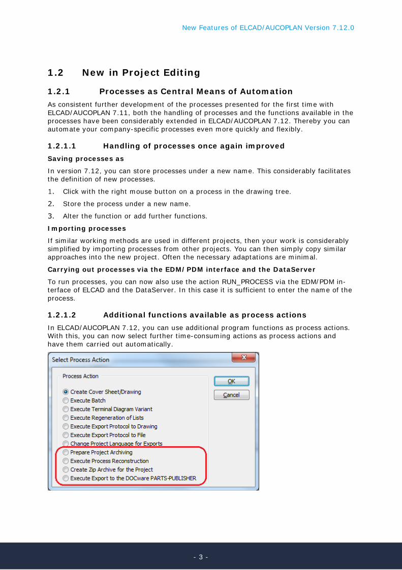
1.2.1.2 Additional functions available as process actions In ELCAD/AUCOPLAN 7.12, you can use additional program functions as process actions. With this, you can now select further time-consuming actions as process actions and have them carried out automatically.
- 3 -
New Features of ELCAD/AUCOPLAN Version 7.12.0
Preparing project archiving
You can use this process action to prepare the archiving process for the project. You are offered the dialog "Prepare Project Archiving". If you have already defined specifications for archiving, then these are entered as defaults.
Carrying out a project reconstruction
You can use this process action to reconstruct the project. You are offered the dialog "Ex-ecute Project Reconstruction". Specify now the options for reconstructing the project. If you select the option "Evaluate Project", then you are subsequently offered the dialog for specifying the evaluation runs.
Creating a ZIP archive for the project
With this action you can create a ZIP file backup of the current project. You are offered the dialog "Create ZIP archive for project".
Exporting to the DOCware PARTS-PUBLISHER
With this action you can export the project to the DOCware PARTS-PUBLISHER. This pro-cess action is only available if you have a DOCware export license.
Moreover you can now use the button [Test] in the properties dialog of each process to test the process before it is executed. This function is used to check whether the actions specified for the process can be carried out.
1.2.2 Reconstructing an Re-Evaluating a Project Already in many previous versions, you could click with the right mouse button on the project node of the drawing tree to carry out the function "Reconstruct Project". If you activate the checkbox "Evaluate Project" in the subsequent dialog, then the project is re-evaluated immediately after the reconstruction.
What is new in version 7.12 is that you can directly configure the specification of the evaluation runs once the checkbox has been activated.
- 4 -
New Features of ELCAD/AUCOPLAN Version 7.12.0
1.3 New in Drawing Editing
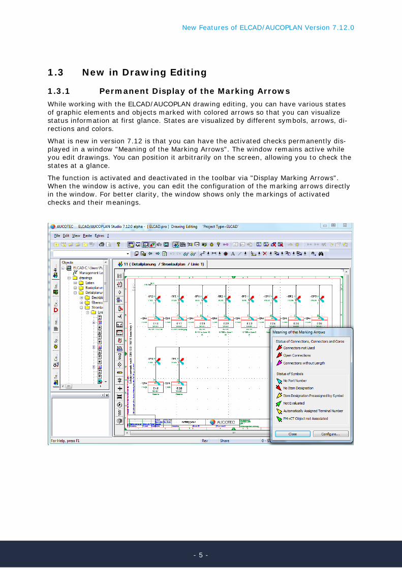
1.3.1 Permanent Display of the Marking Arrows While working with the ELCAD/AUCOPLAN drawing editing, you can have various states of graphic elements and objects marked with colored arrows so that you can visualize status information at first glance. States are visualized by different symbols, arrows, di-rections and colors.
What is new in version 7.12 is that you can have the activated checks permanently dis-played in a window "Meaning of the Marking Arrows". The window remains active while you edit drawings. You can position it arbitrarily on the screen, allowing you to check the states at a glance.
The function is activated and deactivated in the toolbar via "Display Marking Arrows". When the window is active, you can edit the configuration of the marking arrows directly in the window. For better clarity, the window shows only the markings of activated checks and their meanings.
- 5 -
New Features of ELCAD/AUCOPLAN Version 7.12.0
1.3.2 Replacing Symbol Texts and Free Texts in the Drawing Tree
The function "Replace symbol texts and free texts" has been available in several older versions as action in batch processing. In ELCAD/AUCOPLAN 7.12, this function is now also available in the drawing tree.
You start the function with the right mouse button on:
• Individual drawings • A selection of marked drawings • A folder with drawings • The Drawings folder in the root folder of the project You are then offered the dialog for replacing symbol texts and free texts already familiar from batch processing.
1.3.3 Navigating via Core Symbols New in version 7.12: You can start a navigation in drawing editing also from core sym-bols if the cable management is active in the project.
To do this, start navigating from the menu or the command line and select the core sym-bol of your choice. You are then graphically shown all cores of the cable one by one, no matter in which drawing they are located. With each displayed core you can decide whether to continue or to discontinue the navigation.
When the drawing tree is not open, then the function "Identify" is alternatively offered in the right mouse button menu.
1.3.4 Representation Filter when Copying from Template Projects
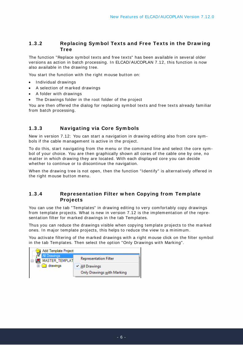
You can use the tab "Templates" in drawing editing to very comfortably copy drawings from template projects. What is new in version 7.12 is the implementation of the repre-sentation filter for marked drawings in the tab Templates.
Thus you can reduce the drawings visible when copying template projects to the marked ones. In major template projects, this helps to reduce the view to a minimum.
You activate filtering of the marked drawings with a right mouse click on the filter symbol in the tab Templates. Then select the option "Only Drawings with Marking".
- 6 -
New Features of ELCAD/AUCOPLAN Version 7.12.0
1.3.5 New Dialog when Outputting Revisions In ELCAD/AUCOPLAN 7.12, the dialogs for outputting revisions were combined so that you can normally enter the complete definition in one dialog. This also includes the input of the optional revision comments, which you can specify in the project configuration.
1.3.6 Changing the Properties of Symbol Texts In ELCAD/AUCOPLAN 7.12, you can now with one click access the function for changing the properties of texts in already placed symbols: The function as such is older but was formerly accessible only from the menu.
Now you find the menu item SYMBOL TEXTS PROPERTIES in the context menu.
- 7 -
New Features of ELCAD/AUCOPLAN Version 7.12.0
When you select this menu item, the symbol is scaled, and the symbol texts are shown in green. If you now select a text, you can move it and also use the subsequent dialog to specify the text properties and the visibility.
1.4 New in Symbol Editing
1.4.1 Integration of Bar Codes, QR Codes and other referenced Graphics into ELCAD
A new function allows you to integrate referenced graphic files into symbols and to repre-sent them with ELCAD/AUCOPLAN 7.12. In this process ELCAD provides the interoperabil-ity from symbol design via the master data to the drawing editing and the parts list.
This new function allows you to reference to bar codes, QR codes and other graphics files, such as data sheets, product illustrations or adjustment data in symbols, without defining them in the phase of symbol design as you could already do it before.
Thus, you can select and insert bar codes or QR codes in the different planning stages and hand them over to the graphical lists. New functions had been implemented to the following areas therefore:
• In symbol design • In drawing editing • In the master data editing and the parts list
Supported graphic formats are:
• BMP • PCX • TIF • JPG
This function is initiated by means of the new code numbers 5130 … 5135. Graphic files can be assigned to these code numbers in any projecting step in order to display them later in the drawings.
- 8 -
New Features of ELCAD/AUCOPLAN Version 7.12.0
1.4.1.1 Preparation of the Symbol Dialogs The preparations to use the function start in the symbol design. For every type of graphic files, to which you want to reference later on, you should provide a separate dialog with a separate code number (5130 … 5135) in the symbol. Provide a significant text (QR code, bar code, data sheet etc.) in the Meaning column as well.
This is advisable in order to access the centrally organized data in different folders in a structured way later on.
For each symbol, in which you want to display referenced graphic files, you must add at least one code number from the range 5130 … 5135.
Please note that in symbols the length of paths is limited to 58 characters. If you use longer paths, we recommend the use of symbolic paths. By this method, you can central-ly assign a symbolic path name to a long path in the AucSys.ini or aucotec.ini file, to which you can later refer easily by its name. Please refer to the System Administrator manual for more details.
In the sample data of ELCAD the symbolic path $modpath is used to limit the path length.
- 9 -
New Features of ELCAD/AUCOPLAN Version 7.12.0
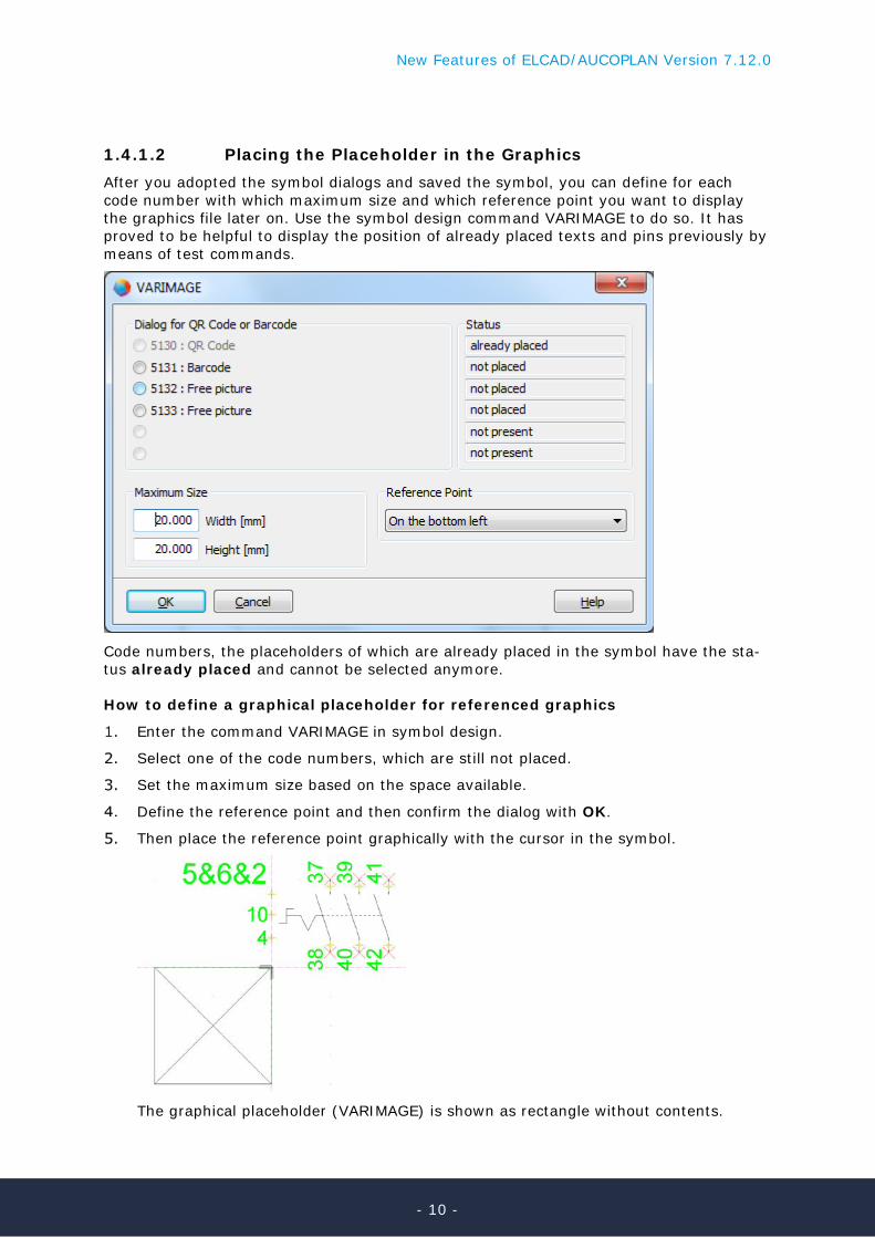
1.4.1.2 Placing the Placeholder in the Graphics After you adopted the symbol dialogs and saved the symbol, you can define for each code number with which maximum size and which reference point you want to display the graphics file later on. Use the symbol design command VARIMAGE to do so. It has proved to be helpful to display the position of already placed texts and pins previously by means of test commands.
Code numbers, the placeholders of which are already placed in the symbol have the sta-tus already placed and cannot be selected anymore.
How to define a graphical placeholder for referenced graphics
Enter the command VARIMAGE in symbol design.
Select one of the code numbers, which are still not placed.
Set the maximum size based on the space available.
Define the reference point and then confirm the dialog with OK.
Then place the reference point graphically with the cursor in the symbol.
The graphical placeholder (VARIMAGE) is shown as rectangle without contents.
- 10 -
New Features of ELCAD/AUCOPLAN Version 7.12.0
By defining the maximum size, you can optimally specify the free space, which might be available later in the diagram. You can specify separate values for a maximum width and a maximum height. Since ELCAD does not change the aspect ratio when placing the graphics, the maximum value, which will be exceeded first, controls the maximum size shown.
By defining the code numbers and the placeholders in the symbol design, you finished all necessary preparations. You can assign the graphics file in later process steps.
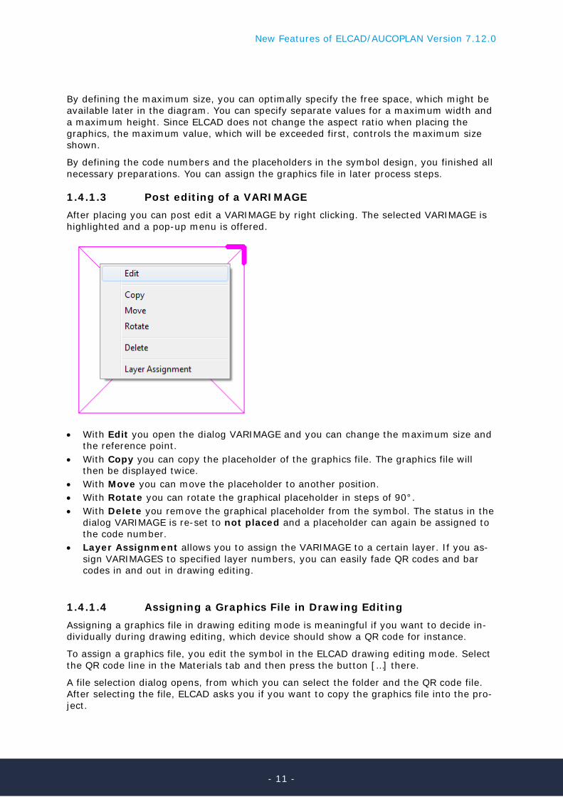
1.4.1.3 Post editing of a VARIMAGE After placing you can post edit a VARIMAGE by right clicking. The selected VARIMAGE is highlighted and a pop-up menu is offered.
• With Edit you open the dialog VARIMAGE and you can change the maximum size and
the reference point. • With Copy you can copy the placeholder of the graphics file. The graphics file will
then be displayed twice. • With Move you can move the placeholder to another position. • With Rotate you can rotate the graphical placeholder in steps of 90°. • With Delete you remove the graphical placeholder from the symbol. The status in the
dialog VARIMAGE is re-set to not placed and a placeholder can again be assigned to the code number.
• Layer Assignment allows you to assign the VARIMAGE to a certain layer. If you as-sign VARIMAGES to specified layer numbers, you can easily fade QR codes and bar codes in and out in drawing editing.
1.4.1.4 Assigning a Graphics File in Drawing Editing Assigning a graphics file in drawing editing mode is meaningful if you want to decide in-dividually during drawing editing, which device should show a QR code for instance.
To assign a graphics file, you edit the symbol in the ELCAD drawing editing mode. Select the QR code line in the Materials tab and then press the button […] there.
A file selection dialog opens, from which you can select the folder and the QR code file. After selecting the file, ELCAD asks you if you want to copy the graphics file into the pro-ject.
- 11 -
New Features of ELCAD/AUCOPLAN Version 7.12.0
After selecting the graphics file, it is displayed at the symbol, scaled to the size to which it had been defined at the symbol before.
You will find some sample data for QR codes or bar codes in the data shipped with ELCAD. The examples are stored parallel to the project folder in a separate folder named REFERENCED FILES.
- 12 -
New Features of ELCAD/AUCOPLAN Version 7.12.0
1.4.1.5 Assigning a Graphics File via Master Database If you want to assign graphics files in general to devices, we recommend that you assign the graphics files via the master database. In the master database, you can use the code numbers 5130 … 5135 as well and provide the graphics files there for the parts required.
After the assigning the part number to the symbol, the names of the graphics files are transferred automatically into the drawing symbols, into the lists and into all other repre-sentations of the device, that contain the appropriate code numbers.
To achieve this, you must append the code numbers (5130 … 5135) to the structure of the database, the structure of the parts list, the parts list symbols and the formats.
In this way, you can also transfer further parts information like bar codes or adjustment data into the graphical list and display it.
- 13 -
New Features of ELCAD/AUCOPLAN Version 7.12.0
1.5 New Features of the Item Editor
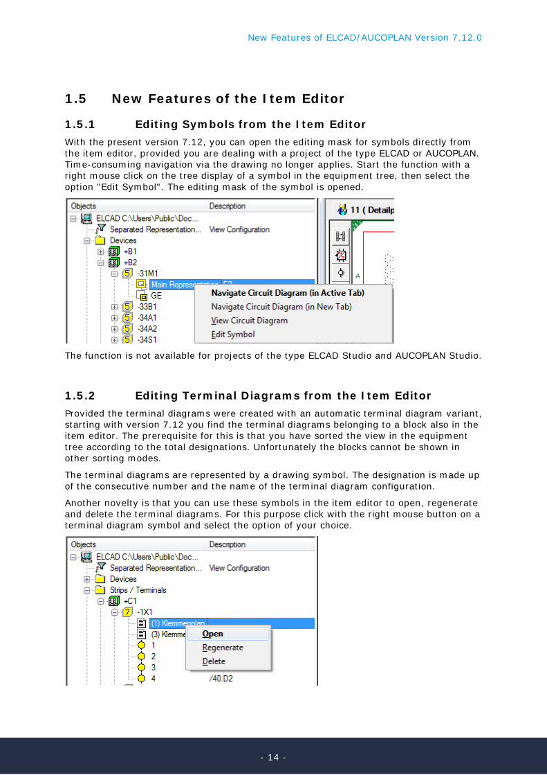
1.5.1 Editing Symbols from the Item Editor With the present version 7.12, you can open the editing mask for symbols directly from the item editor, provided you are dealing with a project of the type ELCAD or AUCOPLAN. Time-consuming navigation via the drawing no longer applies. Start the function with a right mouse click on the tree display of a symbol in the equipment tree, then select the option "Edit Symbol". The editing mask of the symbol is opened.
The function is not available for projects of the type ELCAD Studio and AUCOPLAN Studio.
1.5.2 Editing Terminal Diagrams from the Item Editor Provided the terminal diagrams were created with an automatic terminal diagram variant, starting with version 7.12 you find the terminal diagrams belonging to a block also in the item editor. The prerequisite for this is that you have sorted the view in the equipment tree according to the total designations. Unfortunately the blocks cannot be shown in other sorting modes.
The terminal diagrams are represented by a drawing symbol. The designation is made up of the consecutive number and the name of the terminal diagram configuration.
Another novelty is that you can use these symbols in the item editor to open, regenerate and delete the terminal diagrams. For this purpose click with the right mouse button on a terminal diagram symbol and select the option of your choice.
- 14 -
New Features of ELCAD/AUCOPLAN Version 7.12.0
1.6 New in List Editing
1.6.1 New Status List Working Status ELCAD/AUCOPLAN 7.12 has a new status list Working Status. You use it to determine the working status of the objects in all drawings in the project. Unusual findings are classified according to the categories error, warning and info and are entered in the list.
The status list is filled with data or updated via the menu item REGENERATE in the con-text menu.
The dialog "Determine Project Working Status" offers a selection of checks you can carry out.
Default: all checks are activated. Select the checks of your choice and confirm the dialog with OK.
Errors
• A core symbol has no connection reference. • A part number is not present in the cable master data. • A part number is not present in the device master data. • An external document is not present. • A core symbol refers to a wrong assignment. Warnings
• A symbol is not evaluated. • A symbol is not evaluated and has no item designation. • A core symbol is not evaluated. • A core symbol is placed on an ambiguous connection. • A core symbol is placed on a connection node without device pins. • A cable run symbol for multi-cable representation is not associated with the database. • A cable run symbol for single-cable representation is not associated with the data-
base. • An instrumentation symbol is not associated with the database. • A tag symbol is not associated with the database. • A signal symbol is not associated with the database.
- 15 -
New Features of ELCAD/AUCOPLAN Version 7.12.0
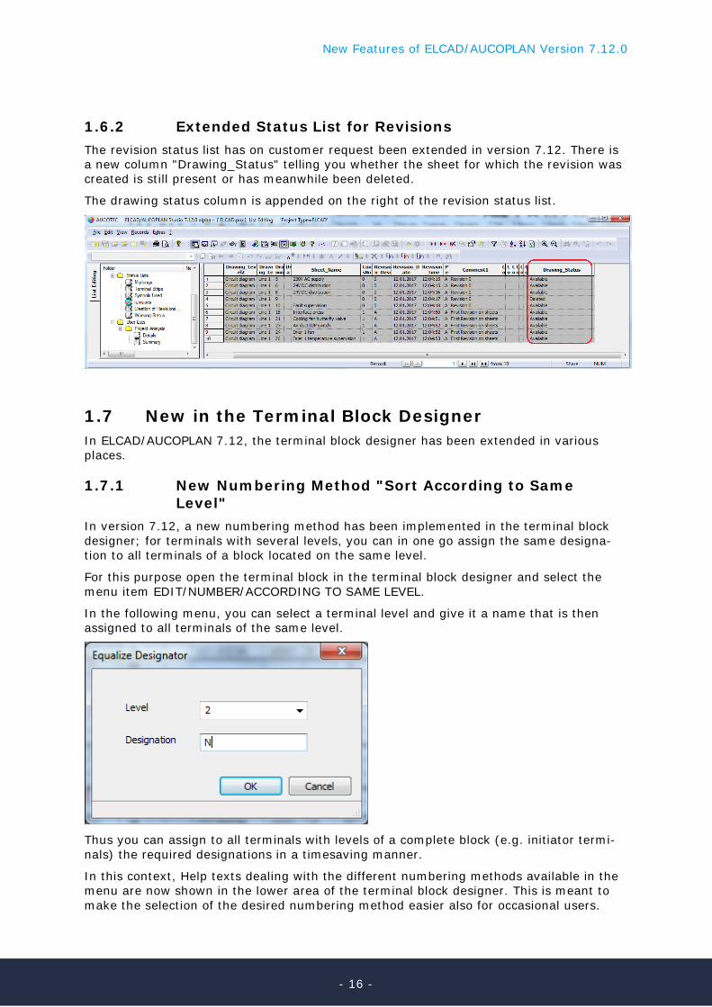
1.6.2 Extended Status List for Revisions The revision status list has on customer request been extended in version 7.12. There is a new column "Drawing_Status" telling you whether the sheet for which the revision was created is still present or has meanwhile been deleted.
The drawing status column is appended on the right of the revision status list.
1.7 New in the Terminal Block Designer In ELCAD/AUCOPLAN 7.12, the terminal block designer has been extended in various places.
1.7.1 New Numbering Method "Sort According to Same Level"
In version 7.12, a new numbering method has been implemented in the terminal block designer; for terminals with several levels, you can in one go assign the same designa-tion to all terminals of a block located on the same level.
For this purpose open the terminal block in the terminal block designer and select the menu item EDIT/NUMBER/ACCORDING TO SAME LEVEL.
In the following menu, you can select a terminal level and give it a name that is then assigned to all terminals of the same level.
Thus you can assign to all terminals with levels of a complete block (e.g. initiator termi-nals) the required designations in a timesaving manner.
In this context, Help texts dealing with the different numbering methods available in the menu are now shown in the lower area of the terminal block designer. This is meant to make the selection of the desired numbering method easier also for occasional users.
- 16 -
New Features of ELCAD/AUCOPLAN Version 7.12.0
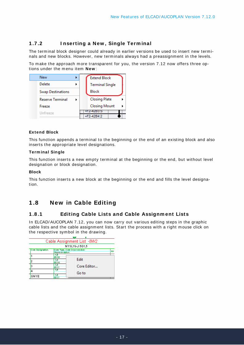
1.7.2 Inserting a New, Single Terminal The terminal block designer could already in earlier versions be used to insert new termi-nals and new blocks. However, new terminals always had a preassignment in the levels.
To make the approach more transparent for you, the version 7.12 now offers three op-tions under the menu item New:
Extend Block
This function appends a terminal to the beginning or the end of an existing block and also inserts the appropriate level designations.
Terminal Single
This function inserts a new empty terminal at the beginning or the end, but without level designation or block designation.
Block
This function inserts a new block at the beginning or the end and fills the level designa-tion.
1.8 New in Cable Editing
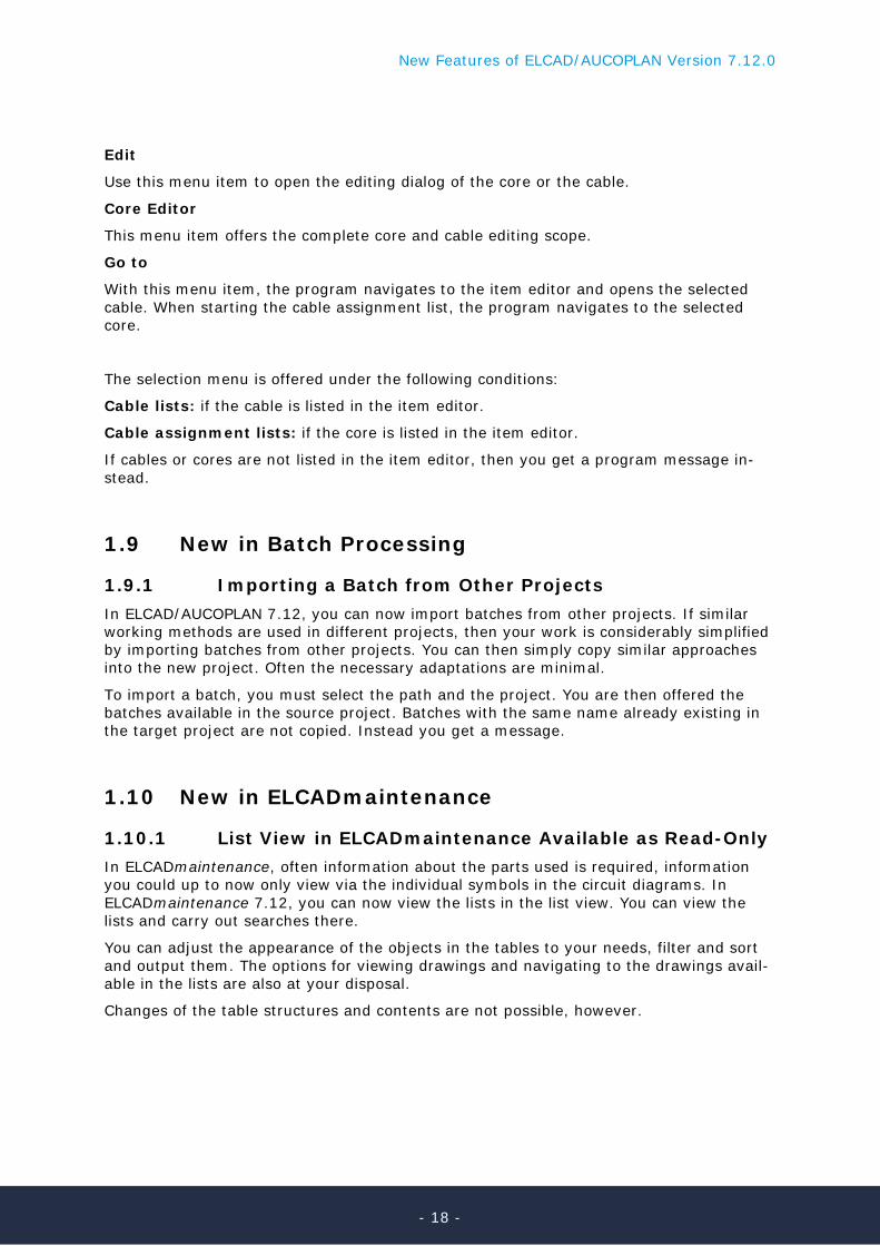
1.8.1 Editing Cable Lists and Cable Assignment Lists In ELCAD/AUCOPLAN 7.12, you can now carry out various editing steps in the graphic cable lists and the cable assignment lists. Start the process with a right mouse click on the respective symbol in the drawing.
- 17 -
New Features of ELCAD/AUCOPLAN Version 7.12.0
Edit
Use this menu item to open the editing dialog of the core or the cable.
Core Editor
This menu item offers the complete core and cable editing scope.
Go to
With this menu item, the program navigates to the item editor and opens the selected cable. When starting the cable assignment list, the program navigates to the selected core.
The selection menu is offered under the following conditions:
Cable lists: if the cable is listed in the item editor.
Cable assignment lists: if the core is listed in the item editor.
If cables or cores are not listed in the item editor, then you get a program message in-stead.
1.9 New in Batch Processing
1.9.1 Importing a Batch from Other Projects In ELCAD/AUCOPLAN 7.12, you can now import batches from other projects. If similar working methods are used in different projects, then your work is considerably simplified by importing batches from other projects. You can then simply copy similar approaches into the new project. Often the necessary adaptations are minimal.
To import a batch, you must select the path and the project. You are then offered the batches available in the source project. Batches with the same name already existing in the target project are not copied. Instead you get a message.
1.10 New in ELCADmaintenance
1.10.1 List View in ELCADmaintenance Available as Read-Only In ELCADmaintenance, often information about the parts used is required, information you could up to now only view via the individual symbols in the circuit diagrams. In ELCADmaintenance 7.12, you can now view the lists in the list view. You can view the lists and carry out searches there.
You can adjust the appearance of the objects in the tables to your needs, filter and sort and output them. The options for viewing drawings and navigating to the drawings avail-able in the lists are also at your disposal.
Changes of the table structures and contents are not possible, however.
- 18 -
New Features of ELCAD/AUCOPLAN Version 7.12.0
1.11 Interfaces
1.11.1 New in the Generating Interface (EDM/PDM) In ELCAD/AUCOPLAN 7.12, the extensive functionality of the processes is now also exe-cutable via the instruction RUN_PROCESS.
Moreover the execution of batches with the instruction RUN_BATCH has been enabled in the interface.
1.11.2 Extended Output of Compact PDF in the Generating Interface (EDM/PDM)
Mit ELCAD/AUCOPLAN 7.12 ist die Ausgabe von kompaktem PDF über die Generier-schnittstelle deutlich variabler geworden. Zudem ist es jetzt möglich, auch navigationsfä-higes PDF über die Schnittstelle zu erzeugen und das Ausgabeziel direkt in der Schnitt-stelle festzulegen. Bisher war die PDF-Ausgabe der Generierschnittstelle an die PDF-Einstellungen der Benutzerkonfiguration gebunden.
Die Ausgabe erfolgt nun mit der Sub Action PDF_COMPACT. Neu ist der Schlüssel "Intelli-gent" in der Section [Pdf]. Damit legen Sie fest, dass Sie navigationsfähiges PDF erzeu-gen.
Mit dem ebenfalls neuen Schlüssel "SaveAsFileName" können Sie in der Schnittstelle di-rekt den Pfad und den Dateinamen für die zu erzeugende PDF-Datei angeben.
1.11.3 New in the DOCware Interface In ELCAD/AUCOPLAN 7.12, you can now select the option to output data via the DOCware interface also as process action. Of course you need a DOCware license for this.
Besides you can also select the language column for the DOCware output. The language code (column header of the translate column) moreover automatically preassigns the folder designation for the output so that you can automatically store different language versions in parallel.
1.11.4 Update of the Interface to the Phoenix Contact Clip Project
The export of block layouts and the import of blocks via the Phoenix Clip Project interface has in ELCAD 7.12 been adapted to the current interface description. Therefore the Phoe-nix Clip Project versions 8.5 and 8.6 are now supported.