This article was downloaded by: [Purdue University] On: 21 March 2013, At: 06:58 Publisher: Taylor & Francis Informa Ltd Registered in England and Wales Registered Number: 1072954 Registered office: Mortimer House, 37-41 Mortimer Street, London W1T 3JH, UK Ferroelectrics Publication details, including instructions for authors and subscription information: http://www.tandfonline.com/loi/gfer20 New fluorinated chiral side-chain polymers with very large tilt angles in the smectic C* phase Holger Poths a , Rudolf Zentel a , David Hermann b , Gunnar Anderson b & Kent Skarp b a Institut für Organische Chemie, Universität Mainz, J.J. Becher Weg 18–20, W-6500, Mainz, Germany b Physics Department, Chalmers University of Technology, S-412 96, Göteborg, Sweden Version of record first published: 10 Feb 2011. To cite this article: Holger Poths , Rudolf Zentel , David Hermann , Gunnar Anderson & Kent Skarp (1993): New fluorinated chiral side-chain polymers with very large tilt angles in the smectic C* phase, Ferroelectrics, 148:1, 285-295 To link to this article: http://dx.doi.org/10.1080/00150199308019956 PLEASE SCROLL DOWN FOR ARTICLE Full terms and conditions of use: http://www.tandfonline.com/page/terms-and-conditions This article may be used for research, teaching, and private study purposes. Any substantial or systematic reproduction, redistribution, reselling, loan, sub-licensing, systematic supply, or distribution in any form to anyone is expressly forbidden. The publisher does not give any warranty express or implied or make any representation that the contents will be complete or accurate or up to date. The accuracy of any instructions, formulae, and drug doses should be independently verified with primary sources. The publisher shall not be liable for any loss, actions, claims, proceedings, demand, or costs or damages whatsoever or howsoever caused arising directly or indirectly in connection with or arising out of the use of this material.
Transcript
This article was downloaded by: [Purdue University]On: 21 March 2013, At: 06:58Publisher: Taylor & FrancisInforma Ltd Registered in England and Wales Registered Number: 1072954 Registeredoffice: Mortimer House, 37-41 Mortimer Street, London W1T 3JH, UK
FerroelectricsPublication details, including instructions for authors andsubscription information:http://www.tandfonline.com/loi/gfer20
New fluorinated chiral side-chainpolymers with very large tilt angles inthe smectic C* phaseHolger Poths a , Rudolf Zentel a , David Hermann b , GunnarAnderson b & Kent Skarp ba Institut für Organische Chemie, Universität Mainz, J.J. Becher Weg18–20, W-6500, Mainz, Germanyb Physics Department, Chalmers University of Technology, S-412 96,Göteborg, SwedenVersion of record first published: 10 Feb 2011.
To cite this article: Holger Poths , Rudolf Zentel , David Hermann , Gunnar Anderson & Kent Skarp(1993): New fluorinated chiral side-chain polymers with very large tilt angles in the smectic C* phase,Ferroelectrics, 148:1, 285-295
To link to this article: http://dx.doi.org/10.1080/00150199308019956
PLEASE SCROLL DOWN FOR ARTICLE
Full terms and conditions of use: http://www.tandfonline.com/page/terms-and-conditions
This article may be used for research, teaching, and private study purposes. Anysubstantial or systematic reproduction, redistribution, reselling, loan, sub-licensing,systematic supply, or distribution in any form to anyone is expressly forbidden.
The publisher does not give any warranty express or implied or make any representationthat the contents will be complete or accurate or up to date. The accuracy of anyinstructions, formulae, and drug doses should be independently verified with primarysources. The publisher shall not be liable for any loss, actions, claims, proceedings,demand, or costs or damages whatsoever or howsoever caused arising directly orindirectly in connection with or arising out of the use of this material.
Ferroelectrics, 1993, Vol. 148, pp. 285-295 Reprints available directly from the publisher Photocopying permitted by license only
0 1993 Gordon and Breach Science Publishers S.A. Printed in the United States of America
NEW FLUORINATED CHIRAL SIDE-CHAIN POLYMERS WITH VERY LARGE TILT ANGLES I N THE SMECTIC C* PHASE
HOLGER POTHS, RUDOLF ZENTEL Institut fur Organische Chemie, Universitat Mainz, J.J. Becher Weg 18-20, W-6500 Mainz, Germany DAVID HERMANN, GUNNAR ANDERSON, KENT SKARP Physics Department, Chalmers University of Technology, S-412 96 Goteborg, Sweden
Abstract. A fluorinated chiral side-chain polysiloxane with very large tilt angles in the ferroelectric phase was studied. The optical response on an applied square wave could be analyzed in detail by an optical/electrical model for the cell, only assuming book-shelf geometry and negligible dielectric director torques. The model yields molecular tilt angles to a high accuracy by a curve-fitting procedure. Comparisons to other mesogenic substituents were also made, and indications were found that small (monatomic) substituents favor large tilt angles.
INTRODUCTION After the first report by Shibaev et al [l] of the synthesis of a side-chain polymer with a ferroelectric smectic phase, several authors have reported studies of such materials [2]-[9]. Due to the large application potential of these polar polymers as electro-optic [lo] and NLO-material [ll], and for piezo- [12] and pyroelectrical [13] devices, it is important to study structure-property relationships and establish models for poly- mer behavior in electrical and optical fields. The main aim of the present paper is to study the detailed electro-optic response of a new fluorinated chiral polysiloxane with large tilt angles in the chiral smectic C-phase (SmC*), and to evaluate the response in terms of an optical/electrical model. It is found that the model describes the switching process to a high accuracy and by curve-fitting yields several parameters, including tilt angle and refractive indices. In addition, tilt-angle measurements for polymers with different side-chain structures, differing in one mesogen substituent, are compared.
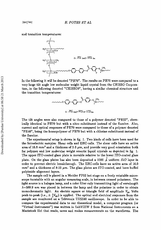
EXPERIMENTAL The main substance under investigation in the present work is the copolymer of a polysiloxane with a fluorinated mesogenic unit, having the following chemical formula
(74511285
Dow
nloa
ded
by [
Purd
ue U
nive
rsity
] at
06:
58 2
1 M
arch
201
3
286/[746] H . POTHS ET AL
and transition temperatures:
\ H,C-Si-
cr. 58oc SmC. 139.c 130
In the following it will be denoted "PH70". The results on PH70 were compared to a very large tilt angle low molecular weight liquid crystal from the CHISSO Corpora- tion, in the following denoted "CHISSOS", having a similar chemical structure and the transition temperatures:
The tilt angles were also compared to those of a polymer denoted "PH52", chem- ically identical to PH70 but with a nitro substituent instead of the fluorine. Also, current and optical responses of PH70 were compared to those of a polymer denoted "PH46", being the homopolymer of PH70 but with a chlorine substituent instead of the fluorine.
The experimental setup is shown in fig. 1. Two kinds of cells have been used for the ferroelectric samples: Shear cells and EHC-cells. The shear cells have an active area of 16.8 mm2 and a thickness of 2-3 pm, and provide very good orientation both for polymer and low molecular weight smectic liquid crystals as depicted in fig. 1. The upper ITO-coated glass plate is movable relative to the lower ITO-coated glass plate. On the glass plates has also been deposited a 1000 A" uniform SiO layer in order to prevent electric breakthrough. The EHC-cells have an active area of 16.0 mm2 and a thickness of 8-10 pm. The glass plates are ITO-coated, and have buffed polyimide alignment layers.
The sample cell is placed in a Mettler FP52 hot stage on a freely rotatable micro- scope turntable with an angular measuring scale, in between crossed polarizers. The light source is a halogen lamp, and a color filter only transmitting light of wavelength A=589.9 nrn was placed in between the lamp and the polarizer in order to obtain monochromatic light. An electric square or triangle field of amplitude V, Volts peak-to-peak (i.e., f ;Vw) is applied. The optical and electrical responses from the sample are monitored on a Tektronix TDS540 oscilloscope. In order to be able to compare the experimental data to our theoretical model, a computer program (or "Virtual Instrument") was written in LabVIEW 2 from National Instruments on a Macintosh IIci that reads, saves and makes measurements on the waveforms. The
Dow
nloa
ded
by [
Purd
ue U
nive
rsity
] at
06:
58 2
1 M
arch
201
3
VERY LARGE TILT ANGLE CHIRAL SIDE-CHAIN POLYMERS [747]/287
communication is done by means of the General Purpose Interface Bus, or GPIB. The curve fitting was performed in KaleidaGraph on the same computer.
Optimum optical setting: yr=22.5"
FIGURE 1 the sample between crossed polarizers are monitored on an oscilloscope.
The experimental setup. The optical and current responses from
Tilt angles and spontaneous polarization have been measured for PH70 as functions of temperature. The tilt angles are measured by the quasi-DC method, i.e. by taking angular readings on the microscope turntable for opposite extinction positions. The spontaneous polarization is measured by numerical integration of the current peak of the electrical response of the cell on an applied triangular wave. The theoretical model for the optical transmission has been fitted to experimental data.
THEORY The theoretical model consists of an optical transmission part and a switching mech- anism part. The basic supposition of the model is that the sample is in the book-shelf geometry.
The transmission of a birefringent crystal between crossed polarizers is given by [14]:
Dow
nloa
ded
by [
Purd
ue U
nive
rsity
] at
06:
58 2
1 M
arch
201
3
288/[748] H . P O T H S E T AL
where 4 denotes the angle between the optic a x i s of the sample and one of the polarizers (fig. 1) ; 8, is the apparent tilt angle; d is the sample thickness; A is the wavelength; and An,ff is the effective birefringence. These quantities are in turn parameterized by the azimuthal angle 'p of the SmC* switching cone (fig. 2) in the following manner:
8, = arctan(tan 80 cos 'p) (2)
= /* -no- (3)
Here, t$ is the angle between the director and the light ray (fig. 2), and i6 related to 'p according to
B0 denotes the SmC* tilt angle. Equations (1)-(4) comprise the optical transmission part of the model.
cos t$ = sin do sin 'p. (4)
FIGURE 2 The SmC* switch- FIGURE 3 The switching process in ing cone. terms of the angle 'p, as seen from the 'po = equilibrium angle with E- base of the SmC* cone. An optical re- field. sponse time T~~~~~~~ can be defined as 80 = SmC* tilt angle. the time it takes to go from 10% to 90% 8, = apparent tilt angle. of the "distance" Acp.
The switching mechanism is described by the equation of motion for the director on the SmC* cone. It is necessary to include this into the model in order to transform the parameter 'p into time t , which is the parameter of the experiment.
Various degrees of simplification have been suggested ([15], [IS]) when construct- ing the equation of motion for the director. We found the model of ref. [15] only, to
Dow
nloa
ded
by [
Purd
ue U
nive
rsity
] at
06:
58 2
1 M
arch
201
3
VERY LARGE TILT ANGLE CHIRAL SIDE-CHAIN POLYMERS 17491/289
work properly, which includes an elastic torque but neglects the dielectric torque:
- PE sin 'p + K cos 'p = 7,+, - d'p dt ' ( 5 )
where P is the ferroelectric polarization, E is the applied electric field, K is an effective elastic constant depending both on the cell thickness as well as the boundary conditions of the cell, and 7,+, is the rotational viscosity of the cone motion. The solution to this equation is given by [15]:
where
1
sin(cp - ' p o ) = I
cosh[n(t - to)]'
K (7)
(8) d( + K2
YIP n =
The angle 'po is the equilibrium angle when a constant, electric field is present, and the time to is defined as the time when 'p takes the value 'po + n/2. The character- istic frequency n together with 'po completely describes the dynamic behavior of the switching.
The electric current due to polarization reversal is easily obtained as the time deriva- tive of the polarization charge:
d dt
i ( t ) = A-(Pcos'p) = APnsin'psin('p - 90) (9)
Eq. (1) with eqs. (2), (3), (4) and (6) inserted into it was taken as the theoretical model to which the optical data were fitted. Electric data were fitted to eq. (9).
Optical response time As the optical response curve for a large tilt angle ferroelectric looks quite different from that of a small tilt angle ferroelectric, it is no longer obvious how to evaluate the optical response time only by inspection. Therefore, we have suggested a way to calculate an optical response time from the parameters n and yo.
In order to compare response times of materials with small and large tilt angles, it is necessary to compare the switching process on the SmC* cone itself rather than comparing directly the time development of the optical transmission; i.e., one must decide a starting point and an ending point in the angle 'p, and then calculate the time it takes to go between these points. Therefore, we have defined the response time to be the time it takes to go from 10% to 90% of the total switching in the angle p. It is important to point out that, also for small tilt angles, the 10% and 90% levels of the angle 'p do not directly correspond to the time instants for the 10% and 90% transmission levels respectively, as eq. (6) is a non-linear transformation
Dow
nloa
ded
by [
Purd
ue U
nive
rsity
] at
06:
58 2
1 M
arch
201
3
290/[750] H . POTHS ET AL
function between t and Q. Our response time definition thus differs from the ordinary 10%-90% optical rise time derived directly from the optical transmission, but instead has the advantage that response times can be compared for small and large tilt angle substances.
If the switching starts at the angle QO, it should go to the opposite equilibrium position T - p0 on field reversal (square wave). The total switching process thus goes through a "distance" of AQ = T - 2990 (see fig. 3). The 10% and 90% levels now become, respectively
Eq. (6) can be rewritten to give time as a function of the angle Q:
Q - 'Po .(to - t ) = In tan ~
2
Thus inserting (PI,-, and 990 according to eqs. (10) into eq. (11) we obtain the times tstarf and tend respectively. On forming the difference t end - ts tarf , to cancels out and we obtain the formula for the response time:
RESULTS AND DISCUSSION
Spontaneous polarization, tilt angle and phase behavior Fig. 4 shows the spontaneous polarization and the tilt angle, respectively, as a function of temperature for PH70. The value changes abruptly, showing the first order character of the phase transition SmC* --t Isotropic. This can be compared to fig. 7c, showing the second order phase transition SmC* + SmA* for the tilt angle, exhibited by PH52. In the high temperature phase the electroclinic effect can be observed a an induced tilt.
Curve fitting The results of a curve fit of eq. (1) to the optical response to an applied square wave of PH70 are shown in fig. 5a, and the results of a curve fit of eq. (9) to the corresponding current response are shown in fig. 5b. As can be seen, our optical/electrical model suffices to describe the experimental data and thus the switching process.
The optical curve fit yields a tilt angle value of 39.4" f 0.8" at 90°C. There are in total 4 optical and 3 electrical parameters, as well as 2 parameters for adjusting the amplitude and the vertical position of the fitted curve; thus, in total 9 parameters are fitted. The optical parameters are 80, d, n,, and no (see the Theory section for notation). The electrical parameters are QO, n and to. The results for these
Dow
nloa
ded
by [
Purd
ue U
nive
rsity
] at
06:
58 2
1 M
arch
201
3
VERY LARGE TILT ANGLE CHIRAL SIDE-CHAIN POLYMERS [751]1291
parameters from the fitting in fig. 5a, along with the mean square error x2 and the regression coefficient R of the curve fit, are:
60 = 39.4" f 0.8" (13) d = 2.6pm f 5.8pm n, = 1.65 f 2.17 no = 1 . 5 0 f 1.85 'Po = 9.1" f 3 . 9 " n = 1648s-' f 115s-'
t o = 1.12ms f 0.04ms ( x 2 = 4.39 - ( R = 0.9998)
The curve fit of the polarization reversal current bump involves the electrical param- eters above, as well as a parameter for the amplitude and a parameter for the
62.5 1 50 F I 37.5 ;
la. 2 1 -
12.5 -
40 aa ma i a o 120 140 160
Temperature ["C]
FIGURE 4 u) The spontaneous polarization as a function of temperature. b) The tilt angle as a function of temperature, showing large tilt angle values and the character of a 1st-order phase transition. Compare fig. 7c.
vertical position of the curve; thus, in total 5 parameters are fitted here. From the amplitude parameter the spontaneous polarization can be calculated (see eq. (9)). The following results were obtained for the curve fit in fig. 5b, along with the mean square error and the regression coefficient:
RAPn = 0.4728V f 0.0008V n = 1642s-' f 3 s - I
t o = 1.180ms f 0.001ms = 27.6" f 0.2"
(x' = 0.00011)
(R = 0.9999)
As can be seen from the above, there are three well-determined parameters: the
Dow
nloa
ded
by [
Purd
ue U
nive
rsity
] at
06:
58 2
1 M
arch
201
3
292/[752] H. POTHS ET AL
tilt angle 80, the characteristic frequency n and time t o . The two latter parameters agree between the optical and the current fit, and in the tilt angle there are small errors. Varying the time limits for the fit of the optical data and taking the average value of the tilt angle and the errors, respectively, yields 80 = (40.3 f 0.5)". The corresponding value for the tilt angle measured by the quasi-DC method in fig. 4b is O0 = (42.0 f 2.0)", where the error limits mainly reflect sytematic errors. The two methods for determining the tilt angle thus agree to within experimental error.
PH70, Current response
Tcmperalur = 89 16 'C
Frrqurncy. 10 Hz
PH70, Current response
I r I I f i - ~ ~ - r Tcmperalur Shear Appbrd ce l l I held 7 - 1 ~ ~ d = - 89 2 4 - 8 16 vm 'C , 1 ' 1 1 3 5 V P p . ~ u a r c W a v e i Frequrnry. 10 Hz 1
FIGURE 5 u) Curve fit of the model to the optical response of the copolymer PH70 on an applied square wave. b) Curve fit of the switching part of the model to the current response of the copolymer on an applied square wave.
The values for the cell thickness and the refractive indices are reasonable, but have large errors. This is probably due to a weak dependence of An,ff on the absolute values of n, and no, respectively; i.e., eq. (3) cannot be rewritten entirely in terms of An=n, - no only, but must also include one of the refractive indices. If one could therefore determine these indices from an independent source, one or both of them could be locked in the curve fitting procedure. One would thereby get smaller errors in the determination of the cell thickness and, if included, one of the index parame- ters.
In the value of p0, finally, there is a considerable discrepancy between the optical and electrical fit. However, varying the time limits for the fit of the optical data leaves 'p0 rather unchanged, whereas varying the time limits for the fit of the current data changes 'p0 quite drastically. Thus, as the time limits are more and more con- centrated around the very top of the polarization reversal current bump, the value of (00 continuously goes down to the value from the optical fit. Furthermore, the values for P, evaluated from (14) are significantly higher than those in fig. 4a. Our conclusions from this is that the model for the current response needs refinement to take into account the cell RC-constant, ionic current contributions, and other factors. As outlined in ref. [15] one can measure the delay time and the half-value width of the current bump and from there calculate both n and (00. Doing this, we obtained agreement with the optical curve fit result for both of the parameters. We thus have reasons to believe that the optical curve fit yields reliable values for (00.
Finally, the curve fit result of the optical response of the low molecular weight
Dow
nloa
ded
by [
Purd
ue U
nive
rsity
] at
06:
58 2
1 M
arch
201
3
VERY LARGE TILT ANGLE CHIRAL SIDE-CHAIN POLYMERS [7531/293
liquid crystal CHISSOS is shown in fig. 6. As can be seen, the electro-optical model works equally well in this case, yielding a tilt angle of 45.0".
CHISSOS, Optlcal response
I / \ .la '"I T cT,T7 \r-,-, r - r -7 - r I
mc -y.u M - - C.... , I IV1
rme fS1
FIGURE 6 Curve fit of the model to the optical response of the low molecu- lar weight liquid crystal CHISSO9.
Optical response time The optical response times could be evaluated from the curve fits according to eq. (12). From the values of the fitted parameters one obtains T~~~~~~~~ = 1.9 ms for PH70 and T~~~~~~~ = 95 p~ for CHISSO9, which are expected values from inspection of the time scales in figs. 5a and 6.
Variation of the chemical substituent In fig. 7a the optical and current responses are shown for PH70 in an 8 pm EHC-cell, and in fig. 7b the same is shown for the chlorine substituted homopolymer PH46 in an 8 pm EHC-cell. PH46 thus also has very large tilt angles. PH46 also goes directly from the SmC* to the isotropic phase.
FIGURE 7 a) Current (trace 2 ) and optical (trace 3) responses of PH70 in an EHC-cell - 8 pm thick. Trace 1 = applied voltage. b) Current and optical responses of the chlorine substituted homopolymer PH46 in an EHC-cell - 8 pm thick. Traces as in a). c) The tilt angle as a function of temperature of the nitro substituted copolymer PH52, showing smaller tilt angle values and the character of a 2nd-order phase transition; the electroclinic effect is seen in the A*-phase.
Dow
nloa
ded
by [
Purd
ue U
nive
rsity
] at
06:
58 2
1 M
arch
201
3
294/[754] H. POTHS ET AL
In fig. 7c is shown the tilt angle as a function of temperature for the nitro substituted copolymer PH52, the maximum value being 32". Taken together, this indicates that large substituents (-NO*) decrease the tilt angle whereas small, i.e. monatomic substituents ( - F , - C l ) favor large tilt angles. Furthermore, the substituent of CHISSO9 is the smallest possible, namely hydrogen, and the tilt angle is 45", sup- porting the indications for the polymers.
CONCLUSIONS 0 A fluorinated chiral side-chain copolymer was found to have very large
0 The tilt angles could be obtained by fitting experimental data to a
0 The model worked equally well for a low molecular weight liquid crystal with
0 Indications were found that small substituents (F-, Cl-, H - ) on the mesogen
tilt angles ( ~ 4 0 " ) in the ferroelectric SmC* phase.
theoretical model, only based on ideal book-shelf geometry.
large tilt angles.
allow for the extremely large tilt angles.
ACKNOWLEDGEMENTS Work supported by the Swedish Natural Science Research Council, the Swedish Tech- nical Science Research Council and the Swedish National board for Industrial and Technical Development. Daniel Lindqvist and Carlo Ruberto are greatfully acknowl- edged for technical assistance.
REFERENCES
[I] V. P. Shibaev, M. V. Kozlowskii, L. A. Beresnev, L. A. Blinov and N. A. Plate, Polym. Bull. 12, 299, (1984).
121 S. Uchida, K. Morita, K. Miyoshi, K. Hashimoto and K. Kawasaki, Mol. Cryst. Liq. Cryst. 155, 93, (1988).
[3] R. Zentel, G. Reckert, B. Sauvarop and H. Kapitza, Mukromol. Chem. 190, 2869, (1989).
[4] G. Scherowsky, A. Schliwa, J. Springer, K. Kuehnpast and W. Trapp, Liq. Cryst. 5, 1281, (1989).
[5] T. Kitazume, T. Ohnogi and K. Ito, J. Am. Chem. Soc. 112, 6608, (1990).
[6] M. Dumon, H. T. Nguyen, M. Mauzac, C. Destrade, M. F. Arachard and H. Gasparoux, Macromolecules, 23, 355, (1990).
[7] J . Naciri, S. Pfeiffer and R. Shashidar, Liq. Cryst. 10, 585, (1991).
[8] H. Poths, G. Anderson, K. Skarp and R. Zentel, Adv. Muter. 4, 792, (1992).
Dow
nloa
ded
by [
Purd
ue U
nive
rsity
] at
06:
58 2
1 M
arch
201
3
VERY LARGE TILT ANGLE CI-IIRAL SIDE-CHAIN POLYMERS [755]/295
[9] M. Svensson, B. Helgee, T. Hjertberg, D. Hermann and K. Skarp, Polym. Bull. 31, 167, (1993).
[lo] K. Yuasa, S. Uchida, T. Sekiya, K. Hashimoto and K. Kawasaki, Ferroelectrics, 122, 53, (1991).
[ll] M. Ozaki, M Utsumi, K. Yoshino and K. Skarp, Jpn. J. Appl. Phys. 32 , L852, (1993).
[12] S. U. Vallerien, F. Kremer, E. W. Fisher, H. Kapitza, R. Zentel and H. Poths, Makromol. Chem., Rapid Commun. 1 1 , 593, (1990).
[13] K. Skarp, G. Andersson, H. Poths, R. Zentel, Pyroelectric eflect in low-molar mass and polymer chiral smectics, paper presented at the 14th International Liquid Crystal Conference, Pisa 1992, poster K-P61.
[14] M. Born and E. Wolf, Principles of Optics, Pergamon Press, ed. 5, (1975).
[15] I. Dahl, S.T. Lagerwall, and K. Skarp, Phys. Rev. A, 36, 4380 (1987).
[16] J.-Z. Xue, M. A. Handschy and N. A. Clark, Ferroelectrics, 73 , 305 (1987).