2012 Microchip Technology Inc. DS41632A-page 1 New Peripherals Tips ‘n Tricks TIPS ‘N TRICKS INTRODUCTION Microchip continues to provide innovative products that are smaller, faster, easier to use and more reliable. Flash-based PIC ® MCUs are used in a wide range of every day products from smoke detectors to industrial, automotive and medical products. The PIC16(L)F150X and PIC10(L)F32X families of devices with on-chip configurable logic cells merge all the advantages of the PIC MCU architecture and the flexibility of Flash program memory with the functional- ity of a configurable digital logic cell. Together they form a low-cost building block with resource savings and external component reduction. The flexibility of Flash and an excellent development tool suite, including a low-cost In-Circuit Debugger, In- Circuit Serial Programming TM (ICSP TM ) and CLC Con- figuration Tool GUI, make these devices ideal for just about any embedded control application. The following series of Tips ‘n Tricks can be applied to a variety of applications to help make the most of digital logic functions using a PIC MCU with on-chip configu- rable logic. TIP 1: EXTENDING AUTO- SHUTDOWN CONDITIONS/INPUTS FOR THE CWG Have you ever found yourself in a situation where your PWM application needs more auto-shutdown condi- tions other than the software driven ones due to resource limitations? Here is a solution. The Complementary Waveform Generator (CWG) has two auto-shutdown condition inputs: the CWG1FLT pin for external conditions, and the output from the Configu- rable Logic Cell (CLC), LCxOUT. Use the CLC to your advantage. By selecting the CLC output as an auto- shutdown source, all of the inputs available to the CLC are now available auto-shutdown conditions for your CWG. TIP 2: GET RID OF THE FET DRIVERS, USE THE CWG In many DC motor control applications, FET drivers are used to insure that the power switching of your motor drive circuit is timed correctly to prevent shoot-through current. However, this adds more components to your applications, thus increasing cost and taking up board space. The solution is the Complementary Waveform Genera- tor (CWG). Using the CWG, you can create dead-band delay, which provides for non-overlapping output sig- nals that drive the motor drive circuit, thus preventing shoot-through current. The CWG contains two 6-bit dead-band delay counters, one for the rising edge of the input source, and the other for the falling edge of the input source. This dead-band delay is timed by counting CWG clock periods from zero up to the value in these two counter registers. See Figure 1, Figure 2, and Figure 3 below. FIGURE 1: DEAD-BAND DELAY SIGNAL DIAGRAM Rising Edge Falling Edge Dead Band Rising Edge Dead Band Falling Edge Dead Band cwg_clock PWM1 CWGxA CWGxB Rising Edge Dead Band Dead Band The Complementary Waveform Generator (CWG), Configurable Logic Cell (CLC), and the Numerically Controlled Oscillator (NCO) Peripherals
Transcript
New Peripherals Tips ‘n TricksThe Complementary Waveform Generator (CWG), Configurable Logic Cell
(CLC), and the Numerically Controlled Oscillator (NCO) Peripherals
TIPS ‘N TRICKS INTRODUCTIONMicrochip continues to provide innovative products thatare smaller, faster, easier to use and more reliable.Flash-based PIC® MCUs are used in a wide range ofevery day products from smoke detectors to industrial,automotive and medical products.
The PIC16(L)F150X and PIC10(L)F32X families ofdevices with on-chip configurable logic cells merge allthe advantages of the PIC MCU architecture and theflexibility of Flash program memory with the functional-ity of a configurable digital logic cell. Together they forma low-cost building block with resource savings andexternal component reduction.
The flexibility of Flash and an excellent developmenttool suite, including a low-cost In-Circuit Debugger, In-Circuit Serial ProgrammingTM (ICSPTM) and CLC Con-figuration Tool GUI, make these devices ideal for justabout any embedded control application.
The following series of Tips ‘n Tricks can be applied toa variety of applications to help make the most of digitallogic functions using a PIC MCU with on-chip configu-rable logic.
TIP 1: EXTENDING AUTO-SHUTDOWN CONDITIONS/INPUTS FOR THE CWGHave you ever found yourself in a situation where yourPWM application needs more auto-shutdown condi-tions other than the software driven ones due to
resource limitations? Here is a solution. TheComplementary Waveform Generator (CWG) has twoauto-shutdown condition inputs: the CWG1FLT pin forexternal conditions, and the output from the Configu-rable Logic Cell (CLC), LCxOUT. Use the CLC to youradvantage. By selecting the CLC output as an auto-shutdown source, all of the inputs available to the CLCare now available auto-shutdown conditions for yourCWG.
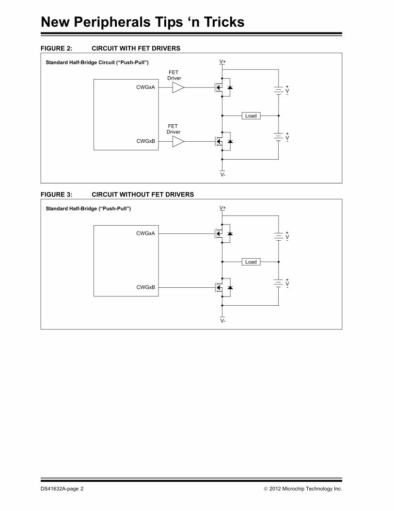
TIP 2: GET RID OF THE FET DRIVERS, USE THE CWGIn many DC motor control applications, FET drivers areused to insure that the power switching of your motordrive circuit is timed correctly to prevent shoot-throughcurrent. However, this adds more components to yourapplications, thus increasing cost and taking up boardspace.
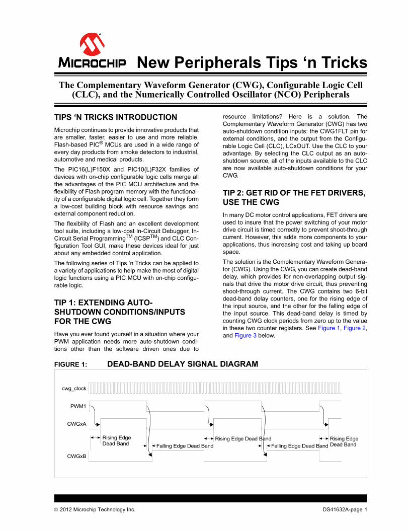
The solution is the Complementary Waveform Genera-tor (CWG). Using the CWG, you can create dead-banddelay, which provides for non-overlapping output sig-nals that drive the motor drive circuit, thus preventingshoot-through current. The CWG contains two 6-bitdead-band delay counters, one for the rising edge ofthe input source, and the other for the falling edge ofthe input source. This dead-band delay is timed bycounting CWG clock periods from zero up to the valuein these two counter registers. See Figure 1, Figure 2,and Figure 3 below.
FIGURE 1: DEAD-BAND DELAY SIGNAL DIAGRAM
Rising Edge Falling Edge Dead Band
Rising Edge Dead BandFalling Edge Dead Band
cwg_clock
PWM1
CWGxA
CWGxB
Rising Edge Dead Band Dead Band
2012 Microchip Technology Inc. DS41632A-page 1
New Peripherals Tips ‘n Tricks
FIGURE 2: CIRCUIT WITH FET DRIVERS
FIGURE 3: CIRCUIT WITHOUT FET DRIVERS
CWGxB
Load
CWGxA +-
+-
V-
V+
V
V
FETDriver
FETDriver
Standard Half-Bridge Circuit (“Push-Pull”)
CWGxB
Load
CWGxA +-
+-
V-
V+
V
V
Standard Half-Bridge (“Push-Pull”)
DS41632A-page 2 2012 Microchip Technology Inc.
New Peripherals Tips ‘n Tricks
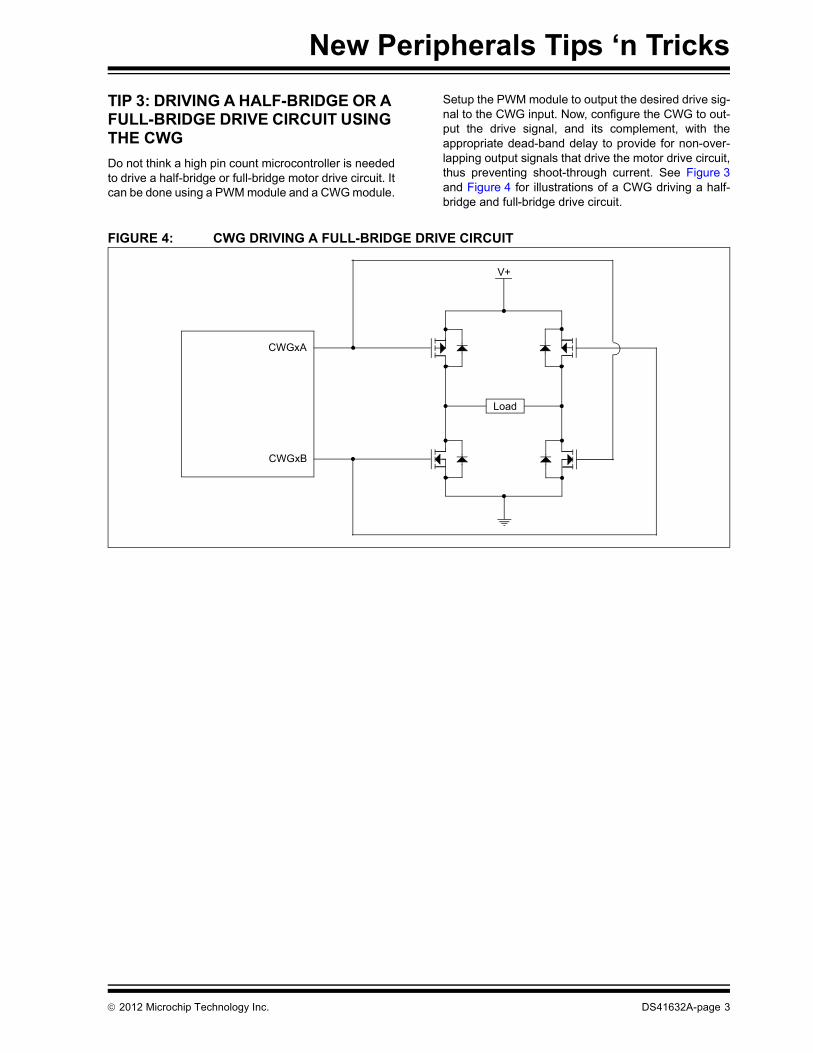
TIP 3: DRIVING A HALF-BRIDGE OR A FULL-BRIDGE DRIVE CIRCUIT USING THE CWGDo not think a high pin count microcontroller is neededto drive a half-bridge or full-bridge motor drive circuit. Itcan be done using a PWM module and a CWG module.
Setup the PWM module to output the desired drive sig-nal to the CWG input. Now, configure the CWG to out-put the drive signal, and its complement, with theappropriate dead-band delay to provide for non-over-lapping output signals that drive the motor drive circuit,thus preventing shoot-through current. See Figure 3and Figure 4 for illustrations of a CWG driving a half-bridge and full-bridge drive circuit.
FIGURE 4: CWG DRIVING A FULL-BRIDGE DRIVE CIRCUIT
CWGxB
V+
Load
CWGxA
2012 Microchip Technology Inc. DS41632A-page 3
New Peripherals Tips ‘n Tricks
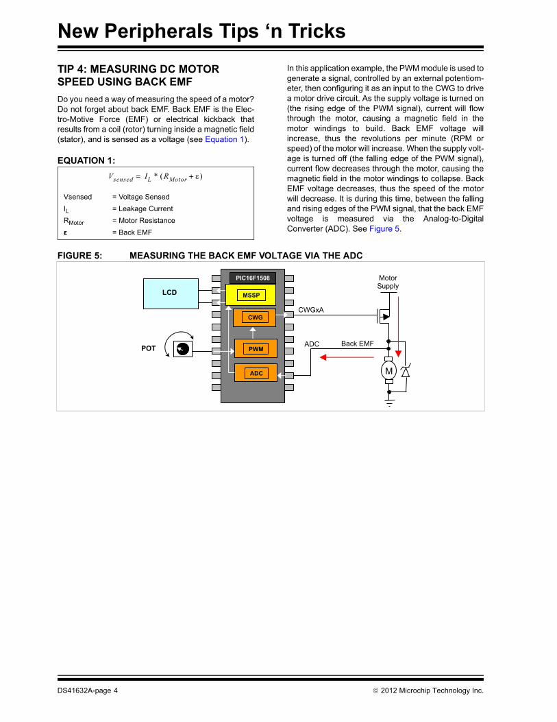
TIP 4: MEASURING DC MOTOR SPEED USING BACK EMFDo you need a way of measuring the speed of a motor?Do not forget about back EMF. Back EMF is the Elec-tro-Motive Force (EMF) or electrical kickback thatresults from a coil (rotor) turning inside a magnetic field(stator), and is sensed as a voltage (see Equation 1).
EQUATION 1:
In this application example, the PWM module is used togenerate a signal, controlled by an external potentiom-eter, then configuring it as an input to the CWG to drivea motor drive circuit. As the supply voltage is turned on(the rising edge of the PWM signal), current will flowthrough the motor, causing a magnetic field in themotor windings to build. Back EMF voltage willincrease, thus the revolutions per minute (RPM orspeed) of the motor will increase. When the supply volt-age is turned off (the falling edge of the PWM signal),current flow decreases through the motor, causing themagnetic field in the motor windings to collapse. BackEMF voltage decreases, thus the speed of the motorwill decrease. It is during this time, between the fallingand rising edges of the PWM signal, that the back EMFvoltage is measured via the Analog-to-DigitalConverter (ADC). See Figure 5.
FIGURE 5: MEASURING THE BACK EMF VOLTAGE VIA THE ADC
Vsensed IL * RMotor + =
Vsensed = Voltage SensedIL = Leakage CurrentRMotor = Motor Resistanceε = Back EMF
M
ADC
CWGxA
Back EMF
CWG
PIC16F1508
MSSP
PWM
ADC
LCD
POT
MotorSupply
DS41632A-page 4 2012 Microchip Technology Inc.
New Peripherals Tips ‘n Tricks
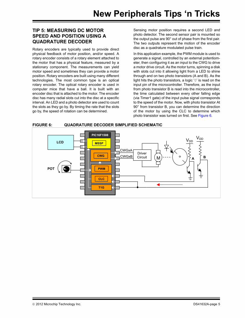
TIP 5: MEASURING DC MOTOR SPEED AND POSITION USING A QUADRATURE DECODERRotary encoders are typically used to provide directphysical feedback of motor position, and/or speed. Arotary encoder consists of a rotary element attached tothe motor that has a physical feature, measured by astationary component. The measurements can yieldmotor speed and sometimes they can provide a motorposition. Rotary encoders are built using many differenttechnologies. The most common type is an opticalrotary encoder. The optical rotary encoder is used incomputer mice that have a ball. It is built with anencoder disc that is attached to the motor. The encoderdisc has many radial slots cut into the disc at a specificinterval. An LED and a photo detector are used to countthe slots as they go by. By timing the rate that the slotsgo by, the speed of rotation can be determined.
Sensing motor position requires a second LED andphoto detector. The second sensor pair is mounted sothe output pulse are 90° out of phase from the first pair.The two outputs represent the motion of the encoderdisc as a quadrature modulated pulse train.
In this application example, the PWM module is used togenerate a signal, controlled by an external potentiom-eter, then configuring it as an input to the CWG to drivea motor drive circuit. As the motor turns, spinning a diskwith slots cut into it allowing light from a LED to shinethrough and on two photo transistors (A and B). As thelight hits the photo transistors, a logic ‘0’ is read on theinput pin of the microcontroller. Therefore, as the inputfrom photo transistor B is read into the microcontroller,the time calculated between every other falling edge(via Timer1 gate) of the input pulse signal correspondsto the speed of the motor. Now, with photo transistor At90° from transistor B, you can determine the directionof the motor by using the CLC to determine whichphoto transistor was turned on first. See Figure 6.
FIGURE 6: QUADRATURE DECODER SIMPLIFIED SCHEMATIC
CWGxACWG
PIC16F1508
MSSP
PWM
CLC
LCD
POT
CWGxBDriverCircuit M
T1G
VDDVDD
A B
2012 Microchip Technology Inc. DS41632A-page 5
New Peripherals Tips ‘n Tricks
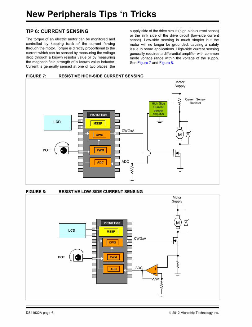
TIP 6: CURRENT SENSINGThe torque of an electric motor can be monitored andcontrolled by keeping track of the current flowingthrough the motor. Torque is directly proportional to thecurrent which can be sensed by measuring the voltagedrop through a known resistor value or by measuringthe magnetic field strength of a known value inductor.Current is generally sensed at one of two places, the
supply side of the drive circuit (high-side current sense)or the sink side of the drive circuit (low-side currentsense). Low-side sensing is much simpler but themotor will no longer be grounded, causing a safetyissue in some applications. High-side current sensinggenerally requires a differential amplifier with commonmode voltage range within the voltage of the supply.See Figure 7 and Figure 8.
FIGURE 7: RESISTIVE HIGH-SIDE CURRENT SENSING
FIGURE 8: RESISTIVE LOW-SIDE CURRENT SENSING
MotorSupply
ADC
CWGxACWG
PIC16F1508
MSSP
PWM
ADC
LCD
POT
High Side Current sensor
amplifier
M
Current Sensor Resistor
MotorSupply
M
ADC
CWGxACWG
PIC16F1508
MSSP
PWM
ADC
LCD
POT
DS41632A-page 6 2012 Microchip Technology Inc.
New Peripherals Tips ‘n Tricks
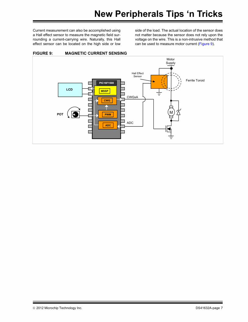
Current measurement can also be accomplished usinga Hall effect sensor to measure the magnetic field sur-rounding a current-carrying wire. Naturally, this Halleffect sensor can be located on the high side or low
side of the load. The actual location of the sensor doesnot matter because the sensor does not rely upon thevoltage on the wire. This is a non-intrusive method thatcan be used to measure motor current (Figure 9).
FIGURE 9: MAGNETIC CURRENT SENSINGMotorSupply
M
Ferrite Toroid
ADC
CWGxACWG
PIC16F1508
MSSP
PWM
ADC
LCD
POT
Hall Effect Sensor
2012 Microchip Technology Inc. DS41632A-page 7
New Peripherals Tips ‘n Tricks
TIP 7: MANCHESTER DECODING USING THE CLC AND NCOIf a EUSART can be used for Manchester encoding, aConfigurable Logic Cell (CLC) and a Numerically Con-trolled Oscillator (NCO) can be used for Manchesterdecoding.
This tip presents a method to decode a Manchesterencoded signal using four CLCs and the NCO to sepa-rate the SPI data signal from a SPI clock signal. SeeFigure 10. After selecting a microcontroller with fourCLCs and an NCO, such as the PIC16F1509, configurethe CLC1 to input the Manchester encoded data signalinto a D flip-flop that is clocked by the inverse of theclock out signal that you are separating. See Figure 11.The inverted output of this flip-flop is the output data
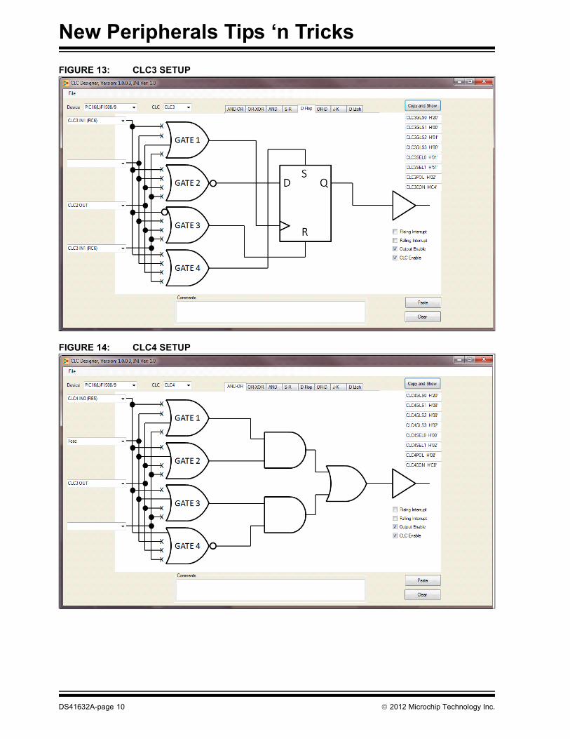
you are decoding. Next, configure the CLC2 to XORthe non-inverted output of CLC1 with the encoded datasignal from the input of CLC1. See Figure 12. ThisXOR output establishes the positive edge to which theoutput data is derived. Use this XOR output to clock theCLC3. See Figure 13. Setup CLC3 using a logic highinput and output CLC3 to the input of CLC4, whichAND-Ors it to the internal oscillator frequency (FOSC) ofthe microcontroller and the clock out signal from theNCO.
See Figure 14. The output signal of CLC4 is then usedto clock the NCO accumulator. This makes the NCOoutput signal the clock frequency to establish theproper timing (the beginning and end of the data signal)to decode the data output signal. See ManchesterDecoder Signal Diagram (Figure 15).
FIGURE 10: MANCHESTER DECODER SIMPLIFIED BLOCK DIAGRAM
2. Configurable Logic Cell (CLC) Configuration ToolGUI software at www.microchip.com
3. Device data sheet for the specific device you areusing, at www.microchip.com
DS41632A-page 12 2012 Microchip Technology Inc.
Note the following details of the code protection feature on Microchip devices:• Microchip products meet the specification contained in their particular Microchip Data Sheet.
• Microchip believes that its family of products is one of the most secure families of its kind on the market today, when used in the intended manner and under normal conditions.
• There are dishonest and possibly illegal methods used to breach the code protection feature. All of these methods, to our knowledge, require using the Microchip products in a manner outside the operating specifications contained in Microchip’s Data Sheets. Most likely, the person doing so is engaged in theft of intellectual property.
• Microchip is willing to work with the customer who is concerned about the integrity of their code.
• Neither Microchip nor any other semiconductor manufacturer can guarantee the security of their code. Code protection does not mean that we are guaranteeing the product as “unbreakable.”
Code protection is constantly evolving. We at Microchip are committed to continuously improving the code protection features of ourproducts. Attempts to break Microchip’s code protection feature may be a violation of the Digital Millennium Copyright Act. If such actsallow unauthorized access to your software or other copyrighted work, you may have a right to sue for relief under that Act.
Information contained in this publication regarding deviceapplications and the like is provided only for your convenienceand may be superseded by updates. It is your responsibility toensure that your application meets with your specifications.MICROCHIP MAKES NO REPRESENTATIONS ORWARRANTIES OF ANY KIND WHETHER EXPRESS ORIMPLIED, WRITTEN OR ORAL, STATUTORY OROTHERWISE, RELATED TO THE INFORMATION,INCLUDING BUT NOT LIMITED TO ITS CONDITION,QUALITY, PERFORMANCE, MERCHANTABILITY ORFITNESS FOR PURPOSE. Microchip disclaims all liabilityarising from this information and its use. Use of Microchipdevices in life support and/or safety applications is entirely atthe buyer’s risk, and the buyer agrees to defend, indemnify andhold harmless Microchip from any and all damages, claims,suits, or expenses resulting from such use. No licenses areconveyed, implicitly or otherwise, under any Microchipintellectual property rights.
2012 Microchip Technology Inc.
QUALITY MANAGEMENT SYSTEM CERTIFIED BY DNV
== ISO/TS 16949 ==
Trademarks
The Microchip name and logo, the Microchip logo, dsPIC, KEELOQ, KEELOQ logo, MPLAB, PIC, PICmicro, PICSTART, PIC32 logo, rfPIC and UNI/O are registered trademarks of Microchip Technology Incorporated in the U.S.A. and other countries.
FilterLab, Hampshire, HI-TECH C, Linear Active Thermistor, MXDEV, MXLAB, SEEVAL and The Embedded Control Solutions Company are registered trademarks of Microchip Technology Incorporated in the U.S.A.
Analog-for-the-Digital Age, Application Maestro, chipKIT, chipKIT logo, CodeGuard, dsPICDEM, dsPICDEM.net, dsPICworks, dsSPEAK, ECAN, ECONOMONITOR, FanSense, HI-TIDE, In-Circuit Serial Programming, ICSP, Mindi, MiWi, MPASM, MPLAB Certified logo, MPLIB, MPLINK, mTouch, Omniscient Code Generation, PICC, PICC-18, PICDEM, PICDEM.net, PICkit, PICtail, REAL ICE, rfLAB, Select Mode, Total Endurance, TSHARC, UniWinDriver, WiperLock and ZENA are trademarks of Microchip Technology Incorporated in the U.S.A. and other countries.
SQTP is a service mark of Microchip Technology Incorporated in the U.S.A.
All other trademarks mentioned herein are property of their respective companies.
Microchip received ISO/TS-16949:2009 certification for its worldwide headquarters, design and wafer fabrication facilities in Chandler and Tempe, Arizona; Gresham, Oregon and design centers in California and India. The Company’s quality system processes and procedures are for its PIC® MCUs and dsPIC® DSCs, KEELOQ® code hopping devices, Serial EEPROMs, microperipherals, nonvolatile memory and analog products. In addition, Microchip’s quality system for the design and manufacture of development systems is ISO 9001:2000 certified.
DS41632A-page 14 2012 Microchip Technology Inc.
AMERICASCorporate Office2355 West Chandler Blvd.Chandler, AZ 85224-6199Tel: 480-792-7200 Fax: 480-792-7277Technical Support: http://www.microchip.com/supportWeb Address: www.microchip.comAtlantaDuluth, GA Tel: 678-957-9614 Fax: 678-957-1455BostonWestborough, MA Tel: 774-760-0087 Fax: 774-760-0088ChicagoItasca, IL Tel: 630-285-0071 Fax: 630-285-0075ClevelandIndependence, OH Tel: 216-447-0464 Fax: 216-447-0643DallasAddison, TX Tel: 972-818-7423 Fax: 972-818-2924DetroitFarmington Hills, MI Tel: 248-538-2250Fax: 248-538-2260IndianapolisNoblesville, IN Tel: 317-773-8323Fax: 317-773-5453Los AngelesMission Viejo, CA Tel: 949-462-9523 Fax: 949-462-9608Santa ClaraSanta Clara, CA Tel: 408-961-6444Fax: 408-961-6445TorontoMississauga, Ontario, CanadaTel: 905-673-0699 Fax: 905-673-6509