KD® DISC CouplingsKD Series of flexible shaft couplingsprovides reliable transmission ofmechanical power from driving todriven machine where a low-maintenance, non-lubricated couplingis required.
KD® Disc Couplings are specificallydesigned to accommodate generalpurpose drive system applicationssuch as centrifugal pumps,compressors, generators, coolingtowers, machine tools, printing andpulp and paper machines.
KD® Couplings transmit torque andprovide for both angular and axialmisalignment between shafts with acoupling comprised of shaft mountedhubs connected through flexible discpacks with spacer or sleeveassemblies.
All KD® Couplings use stainless steeldiscs as flexible members, providinghigh strength and good corrosionresistance. The streamline disk packdesign results in the reaction load onequipment bearings being minimized.These disc pack couplings areinherently self-centering; additionalprovision for limited end float is notrequired.
Most disc packs are unitized and,along with self-locking nuts, theygreatly reduce the number of looseparts, thus simplifying installation andreplacement.
KD® Disc Couplings are now availablein an expanded range of sizes andstyles suitable for commoninstallations. Or if you need somethingspecial, we can design a coupling tomeet your specific requirements.
KD® Disc Couplings
Visit www.kopflex.com
For MoreInformation
21
MT disc pack [ Medium Torque ]unitized, 3 bolt disc with “prestretch”bushings that get pressed into theflanges, uses standard fasteners.KD1, 2
HT disc pack [ High Torque]unitized, 3, 4 or 5 bolt discs, thickerfor high torque, body fit bolts.KD11, 20, 21, 22, 4, 41, 42
HS disc pack [ High Torque - Semi-unitized ]same as HT but semi-unitized so thatthe disc packs may be installed outbetween close-coupled hubs.KD10
CT disc pack [ Cooling Tower ]unitized, 3 bolt disc for coolingtower couplings, stainless steelcomponents with body-fit bolts.KD33
HM disc pack [ High Torque - Marine ]same as HT but with coated discs,for marine applications -DNV approved.
LT disc pack [ Low Torque - Light Duty]non-unitized, most economical,body fit bolts.KD5, 50, 51
1. Coupling Style:Select the appropriate KD® coupling style for your applicationfrom the Product Overview & Index.
2. Coupling Size:Step 1: Determine the proper service factor from page 22.
Step 2: Calculate the required HP/100 RPM, using the HPrating of the drive and the coupling speed (RPM) as shownbelow:
HP x SERVICE FACTOR x 100 = HP/100 RPM
RPM
Step 3: Select the coupling size having a rating sufficientto handle the required HP/100 RPM at the appropriate servicefactor.
Step 4: Verify that the maximum bore of the coupling selectedis equal to or larger than either of the equipment shafts.
Step 5: Check the overall dimensions to ensure the couplingwill not interfere with the coupling guard, piping, or theequipment housings and that it will fit the required shaftseparation.
3. Check Balance RequirementsConsult the Dynamic Balancing Guide on page 23 to helpdetermine if balancing is required. Verify that the maximumoperating speed does not exceed the maximum speed ratingof the coupling.
The maximum speed rating does not consider lateral criticalspeed considerations for floating shaft applications.
4. Specify Shaft SeparationSpecify the required shaft separation using standard length, ifpossible. Verify the actual shaft separation for a replacementapplication.
Note: Care must be exercised in proper selection of any shaftcoupling. The Users must assure themselves that the designof the shaft to coupling hub connection is adequate for theduty intended.
KD® Disc Couplings
Disc Pack DataSelection Procedure
22
KD® Disc Couplings
Service Factors
TypicalApplication Service
FactorAGITATORS
Pure Liquids .......................................................... 1.0Liquids & Solids .................................................... 1.25Liquids — Variable Density ................................... 1.25
NOTES(1) Maximum Torque at the coupling must not exceed
Rated Torque of the coupling.(2) Check local and industrial safety codes.
Values listed are intended only as a generalguide, and are typical of usual servicerequirements. For systems which frequentlyutilize the peak torque capability of the powersource, verify that the magnitude of this peaktorque does not exceed the 1.0 ServiceFactor Rating of the coupling selected.Applications which involve extreme repetitiveshock or high-energy load absorptioncharacteristics should be referred — with fullparticulars — to KOP-FLEX.
Values contained in the table are to beapplied to smooth power sources such aselectric motors and steam turbines. For drivesinvolving internal combustion engines of fouror five cylinders, add 1.0 to the values listed;for six or more cylinders, add 0.5 to the valueslisted. For systems utilizing AC or DC MillMotors as the prime mover, refer to Note (1).
All peoplemovingapplications must be referred to engineering.
23
KD® Disc Couplings
Dynamic Balancing GuideBalancing requirements for a coupling are dependent on factors determinedby the characteristics of the connected equipment. For this reason, theBalancing Charts should be used as a GUIDE ONLY to assist in determiningwhether or not balancing is required.
The Balancing Charts shown are based on AGMA 9000-C90 suggestedbalance classes for systems with “Average” sensitivity to unbalance. Forsystems with higher sensitivity to unbalance, balancing of the coupling maybe required at lower speeds. For systems which are less sensitive tounbalance, couplings may be able to operate at higher speeds than thoseshown at lower balance levels. Therefore, in the absence of either a thoroughsystem analysis or past user experience with a similar installation, thesecharts should be used as a GUIDE ONLY.
KD® Couplings are available in several styles to meet the balancerequirements of API 610, including the 8th Edition. Consult KOP-FLEX fordetails.
KD1 and KD10 couplings meet AGMA Class 8 balance levels as-manufactured (off-the-shelf) and may be component balanced to run at higherspeeds. Refer to the ratings table for the maximum operating speeds fornon-balanced and balanced couplings.
KD11 couplings are designed for higher speeds and meet AGMA Class 9balance as-manufactured. KD11 couplings may be component balanced tomeet Class 10 balance, and may be assembly balanced to Class 11.
KD2®, KD20, and KD21 couplings meet AGMA Class 9 balance balancelevels as-manufactured and may be component balanced to meet Class 10balance. KD2® and KD20 couplings may be assembly balanced to meetAGMA Class 11 balance. KD21 couplings are not assembly balanced. Referto the charts on this page for balancing recommendations.
Balancing of sizes larger than 604 must be considered on a case-by-casebasis. Consult KOP-FLEX for assistance.
For KD4, KD41 and KD42, and KD22 couplings, balance considerationsshould be reviewed on a case-by-case basis. Consult Engineering forassistance. KD5, 50 and 51 couplings are not balanced.
24
CLOSE COUPLEDKD1 with MT Disc Packs Page
Size Range 103 to 453 28, 29Bore Range .50 - 5.50”
Overview Unitized Disc Pack replaced without movingconnected machines
Medium Duty Applications
KD10 with HS Disc Packs 30, 31Size Range 103 to 905Bore Range .50 - 11.50”
Overview Unitized Disc Pack replaced without movingconnected machines
Heavy Duty ApplicationsRatings Similar to Gear Couplings
KD11 with HT Disc Packs 32, 33Size Range 103 to 905Bore Range .50 - 11.50”
Overview Unitized Disc PackHeavy Duty ApplicationsRatings Similar to Gear Couplings
SPACER STYLESKD2® with MT Disc Packs 34, 35
Size Range 023 to 453Bore Range .50 - 7.25”
Overview “Drop-Out” Spacer DesignFactory Assembled Center Flex SectionMedium Duty Applications
KD20 with HT Disc Packs 36, 37Size Range 204 to 905Bore Range 1.00 - 13.50”
Overview “Drop-Out” Spacer DesignFactory Assembled Center Flex SectionHigh Torque Applications
KD21 with HT Disc Packs 38, 39Size Range 053 to 905Bore Range .50 - 13.50”
KD42 with HT Disc Packs 46 - 49Size Range 103 to 905Bore Range .50 - 11.50” Flex Half
Overview Floating Shaft DesignBolts Directly to Gear Coupling RigidsUnitized Disc PackHeavy Duty ApplicationsRatings Similar to Gear Couplings
LIGHT DUTY
KD5, KD50, KD51 with LT Disc Packs 50 - 55Size Range 022 to 362Bore Range .25 - 4.75”
Overview Lighter Duty Applications
Flexible Disc Couplings
Product Overview & Index
KD33
KD4
KD51 Floating Shaft
KD5 Single FlexKD50 Spacer Style
KD42
KD41
KD51T Tubular Floating Shaft
26
NEW
Our Slide Disc Couplings combine the best of two different worlds – themaintenance-free reliability of a disc coupling and the versatile slide feature of a
low-maintenance sliding spline.
For many years, people have been replacing their gearcouplings with maintenance-free disc couplings in orderto eliminate costly lubrication, maintenance and eventualreplacement of their worn out gear couplings. But disccouplings have an inherent limitation that has kept themout of many applications where once only gear couplingswould do the job – the disc packs themselves are nottolerant of significant axial movement. In theseapplications, the conventional thinking was that a slidegear coupling was the only solution.
We offer a solution that combines the best features ofdisc couplings and slide couplings:
• KD® disc packs are supplied as unitizedassemblies with stainless steel discs, whichmakes them easier to assemble and nearlymaintenance-free. Disc packs available,from stock, as an option, with KOPLON*coating for corrosive environments.
• Standard spline sections are sealed andlubricated at the factory. The splines areprovided with minimal backlash and coatedwith a special polymer for long life, minimalmaintenance and low coefficient of friction(reduced sliding force).
• Special slide sections can be supplied toaccommodate special long slideapplications.
Keep in mind that the advantages that KD® Slide Disccouplings offer over gear couplings:
• Disc Couplings require no maintenance,and the spline sections are lubricated at thefactory and do not need to be greased ona regular basis. Operating costs aregreatly reduced compared to gearcouplings!
• Disc Couplings have near zero backlashand standard spline sections are coated forminimal backlash, while gear couplings relyon clearances in the gearing formisalignment, therefore coupling balanceand smooth transmission of power is greatlyimproved over gear couplings. This isimportant where backlash and vibration canaffect the quality of the product beingproduced.
KD® Slide Disc Couplings
Coupling Comments
Slide (Telescope)
*KOPLON is a trademark of E. I. du Pont de Nemours and Company.This trade name, trademark and/or registered trademark is used herein for product comparison purposes only, is the property of its respective owner and is not owned or controlled by EmersonPower Transmission Corporation (EPT). EPT does not represent or warrant the accuracy of this document.
Visit www.kopflex.com
For MoreInformation
27
• Pulp Refiners – replaces slide gear couplingsused to compensate for changing shaftseparation as the refiner wears.
• Polymer Pelletizer – the design shown replaceda slide gear coupling used to compensate forchanging shaft separation as the pelletizerblades wear.
• Fan Application (in tunnels) – shown here, acombination MAX-C® resilient coupling and KD®
Disc Coupling with a spline section is used tocompensate for changes in shaft separationdue to thermal growth.
• Test Stand Application – shown is a special KD®
coupling designed for a high speed test standto accommodate tests of different equipment,requiring different shaft separations.
This is merely a sampling of the different types of applications where disc couplings are being adapted to meetthe slide requirements once thought to be addressed solely by gear couplings.
KD® Slide Disc Couplings
Coupling CommentsTypical Applications:
• Paper Mill Roll Drives – the variable length feature compensates for different shaft separations. Typically,paper mills will have several couplings of the same size, but slightly different shaft separations. One KD®
Slide coupling covers several different shaft separations – eliminating the need for multiple spares.
28
All finish bores and keyways per AGMA 9002-A86 commercial standard tolerances.
Component Parts
KD® Disc Couplings
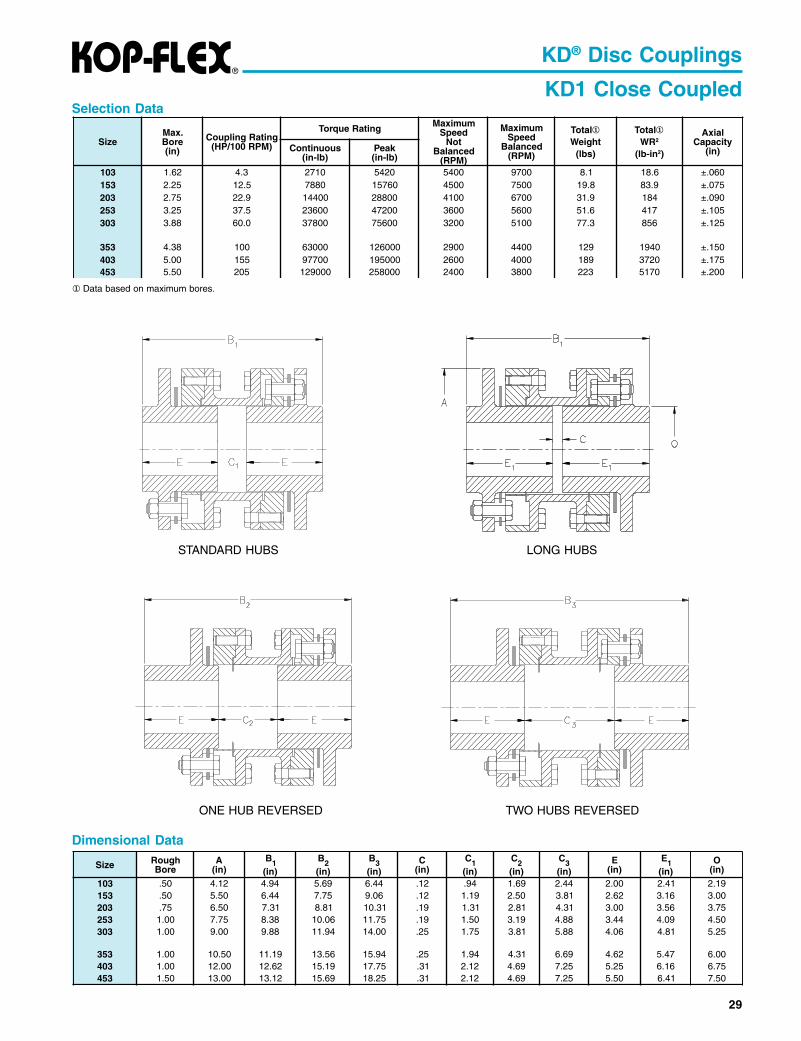
KD1 Close CoupledThe KD1 coupling is designed for close coupledapplications with minimal to short distance between shaftends and light to medium loading. It can directly replacemost REX/THOMAS* DBZ couplings and the unitized discpack design makes the installation simpler and easier.
The KD1 is comprised of two hubs, two rings, two discpacks, and a piloted split spacer. The standard couplinghubs may be installed in any of three mounting positionsfor design and installation flexibility. The split spacer pilotgives the KD1 coupling improved dynamic balancecharacteristics and contains a design feature to hold thesplit spacer in place while the coupling is rotating.
KD1 disc packs are unitized to greatly reduce the numberof loose parts. The split spacer simply drops away fromthe hubs for faster installation and replacement withoutmoving connected machinery. The standard couplingbalance meets AGMA Class 8 as manufactured, dynamicbalance to AGMA Class 9 and conformance to API 610are available options.
For higher power requirements, consider a KD10 disccoupling. For higher speeds, consider a KD11 disccoupling.
KD1 Couplings use MT Disc Packs.
• Medium Duty• Minimal to Short Shaft Separations• Split Spacer with Safety Pilot• Replacement for REX/THOMAS* DBZ• Drop-Out, Unitized Disc Packs
* Center Assembly includes (2) disc packs, (2) disc packfastener sets.
** For Disc Packs and Fastener Sets, do not include “Series”number in the part number.
*REX/THOMAS is a trademark of Rexnord Industries Inc.This trade name, trademark and/or registered trademark is used herein for product comparison purposes only, is the property of its respective owner and is not owned or controlled by EmersonPower Transmission Corporation (EPT). EPT does not represent or warrant the accuracy of this document.
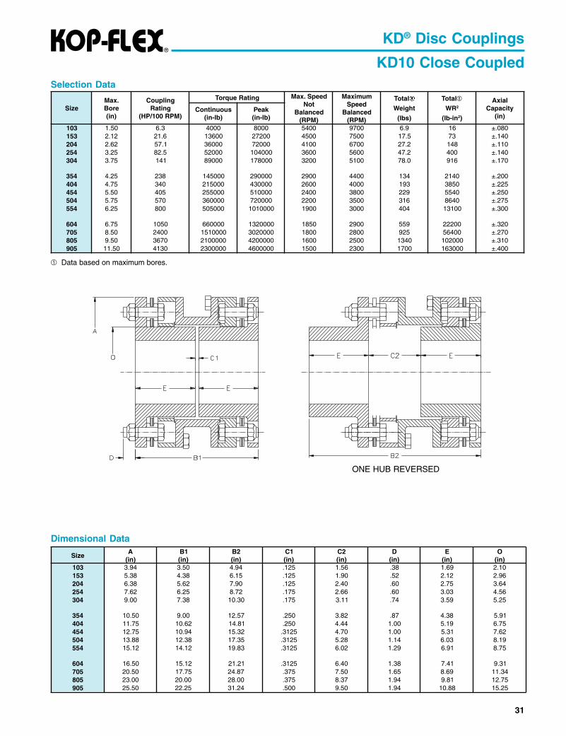
KD10 Close CoupledThe KD10 coupling is designed to work in place ofstandard close coupled gear coupling applications withminimal distance between shaft ends. The power capacityof the KD10 coupling is the highest in the industry, allowingthe easiest conversion from a lubricated coupling to alow maintenance disc coupling.
The KD10 is comprised of two hubs, two rings, two discpacks, and a piloted split spacer. The standard couplinghubs may be installed in two mounting positions for designand installation flexibility. The split spacer pilot gives theKD10 coupling improved dynamic balance characteristicsand contains a design feature to hold the split spacer inplace while the coupling is rotating.
KD10 disc packs are semi-unitized to greatly reduce thenumber of loose parts. The split spacer simply drops awayfrom the hubs for faster installation and replacement ofthe disc packs without moving connected machinery. Thestandard coupling balance meets AGMA Class 8 asmanufactured, dynamic balance to AGMA Class 9 andconformance to API 610 are available options.
For higher speed requirements, consider a KD11 disccoupling.
KD10 couplings use HS Semi-Unitized Disc Packs,for easy replacement without moving connectedequipment.
• Heavy Duty, Highest Power Capacity• Minimal Shaft Separations• Split Spacer with Safety Pilot• Replacement for Standard Gear Couplings• Drop-Out, Semi-Unitized Disc Packs
Complete Couplings Component Parts
All finish bores and keyways per AGMA 9002-A86commercial standard tolerances.
How to Order Components
* Center Assembly includes (2) disc packs, (2) discpack fastener sets.
** For Disc Packs and Fastener Sets, do not include“Series” number in the part number.
Note: Complete couplings are supplied with HT DiscPacks (HTDP) for ease of initial installation. HS DiscPacks (HSDP) should be used for replacementwithout moving connected equipment.
KD11 Close CoupledThe KD11 coupling is designed to work in place ofstandard close coupled gear coupling applications withhigher speed service. The power capacity of the KD11coupling is the highest in the industry, allowing the easiestconversion from a lubricated coupling to a lowmaintenance disc coupling.
The KD11 is comprised of two hubs, two adapters, andtwo disc packs. The standard coupling hubs may beinstalled in any of three mounting positions for designand installation flexibility. The bolted adapters give theKD11 coupling the best dynamic balance characteristicsand allow the connected equipment to be installed orremoved while keeping each assembled half couplingundisturbed.
KD11 disc packs are unitized to greatly reduce the numberof loose parts. The standard coupling balance meetsAGMA Class 9 as manufactured, dynamic balance toAGMA Class 10 and 11, and conformance to API 610are available options. The close tolerance bolts and safetyoverload washers provide superior performance.
For lower speed requirements, consider a KD10 disccoupling. For medium-duty, consider a KD1 disc coupling.
KD11 couplings use HT Disc Packs.
• Heavy Duty, Highest Power Capacity• Minimal Shaft Separations• Bolted Adapters for Higher Speeds• Replacement for Standard Gear Couplings• Unitized Disc Packs
Complete Couplings Component Parts
All finish bores and keyways per AGMA 9002-A86commercial standard tolerances.
How to Order Components
* For Disc Packs and Fastener Sets, do not include“Series” number in the part number.
Note: For Finish Bore add FB to Part Number and specify bore.All finish bores and keyways per AGMA 9002-A86 commercial standard tolerances.
Component Parts
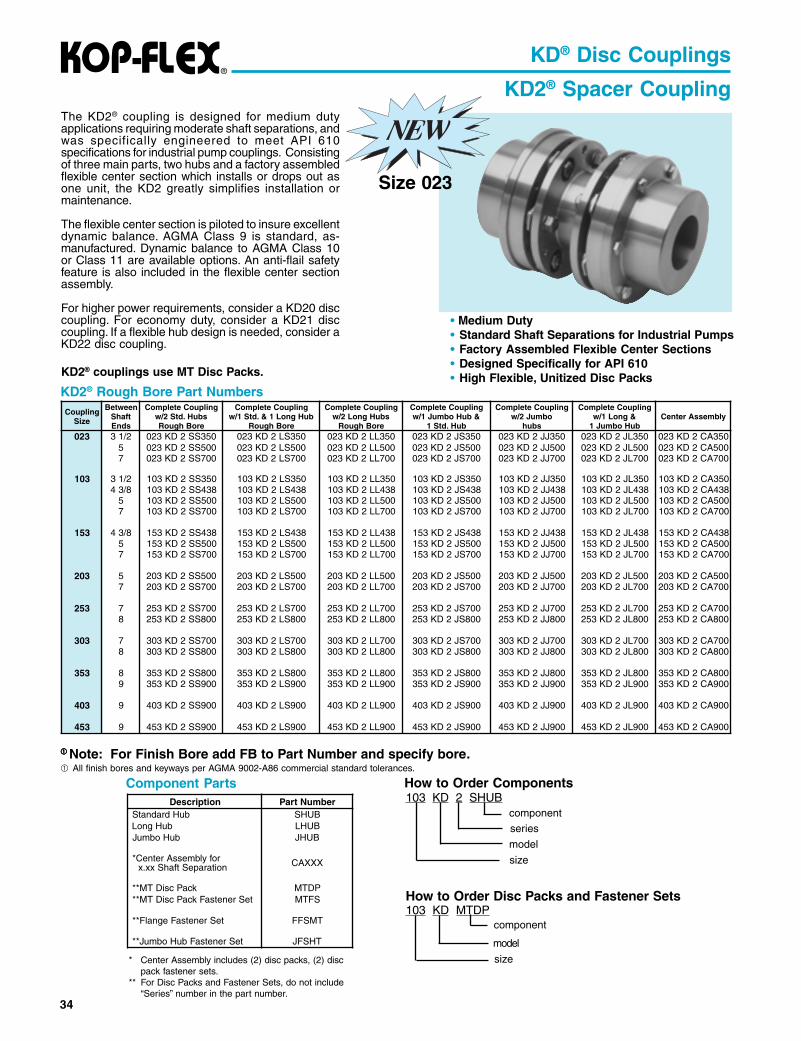
The KD2® coupling is designed for medium dutyapplications requiring moderate shaft separations, andwas specifically engineered to meet API 610specifications for industrial pump couplings. Consistingof three main parts, two hubs and a factory assembledflexible center section which installs or drops out asone unit, the KD2 greatly simplifies installation ormaintenance.
The flexible center section is piloted to insure excellentdynamic balance. AGMA Class 9 is standard, as-manufactured. Dynamic balance to AGMA Class 10or Class 11 are available options. An anti-flail safetyfeature is also included in the flexible center sectionassembly.
For higher power requirements, consider a KD20 disccoupling. For economy duty, consider a KD21 disccoupling. If a flexible hub design is needed, consider aKD22 disc coupling.
KD2® couplings use MT Disc Packs.
• Medium Duty• Standard Shaft Separations for Industrial Pumps• Factory Assembled Flexible Center Sections• Designed Specifically for API 610• High Flexible, Unitized Disc Packs
How to Order Components
* Center Assembly includes (2) disc packs, (2) discpack fastener sets.
** For Disc Packs and Fastener Sets, do not include“Series” number in the part number.
How to Order Disc Packs and Fastener Sets103 KD MTDP
Data based on Min. “C” dimensions, maximum bores and standard hubs.See Balance Specifications page 23. Consult engineering for applications where speed exceed 75% of max. speed rating.
Note: Shaft separations longer than stock may be accomodated by using stock center assemblies and counterboring and overhanging longhubs to make up the difference. Shaft fit length should be equal to "E" or greater. Consult KOP-FLEX for more details.
Visit www.kopflex.com
For MoreInformation
36
KD® Disc Couplings
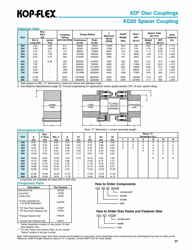
KD20 Spacer CouplingThe KD20 coupling is designed for heavy duty applicationsrequiring moderate shaft separations, and was specificallyengineered to meet API 610 specifications for industrialpump couplings. Consisting of three main parts, two hubsand a factory assembled flexible center section whichinstalls or drops out as one unit, the KD20 greatlysimplifies installation or maintenance.The larger size couplings available in the KD20 Seriesallow application to larger, high power machines. Theflexible center section is piloted to provide excellentdynamic balance. AGMA Class 9 is standard, asmanufactured. Dynamic balance to AGMA Class 10 orClass 11 are available options. The close tolerance boltsand safety overload washers provide superiorperformance and trouble-free operation. An anti-flail safetyfeature is also included in the flexible center sectionassembly.For smaller sizes or lower power requirements, considera KD2 disc coupling. For economy duty, consider a KD21disc coupling. If a flexible hub design is needed, considera KD22 disc coupling.
KD20 Couplings use HT Disc Packs.
• Heavy Duty, Larger Sizes• Standard Shaft Separations for Industrial Pumps• Factory Assembled Flexible Center Sections• Designed Specifically for API 610• High Power, Unitized Disc Packs
KD20 Rough Bore Part Numbers
Note: For Finish Bore add FB to Part Number and specify bore.All finish bores and keyways per AGMA 9002-A86 commercial standard tolerances.
Data based on Min. “C” dimensions, maximum bores and standard hubs. See Balance Specifications page 23. Consult engineering for applications where speed exceed 75% of max. speed rating.
* Long hubs are available for sizes 204 to 454 only.
Component Parts How to Order Components
* Center Assembly includes (2) disc packs, (2) discpack fastener sets.
** For Disc Packs and Fastener Sets, do not include“Series” number in the part number.
103 KD 20 SHUB
size
model
component
series
How to Order Disc Packs and Fastener Sets103 KD HTDP
7 8 9 01 21 41402 26.6 05.4 00.6 52.2 26.3 57.4 88.3 83.3 X X X X X X452 88.7 05.5 00.6 88.2 52.4 57.5 88.4 05.4 X X X X X X403 52.9 44.6 00.7 83.3 57.4 57.6 05.5 00.5 X X X X X X453 57.01 13.7 05.8 00.4 83.5 57.7 52.6 05.5 X X X X404 00.21 05.8 00.01 44.4 21.6 00.9 00.7 52.6 X X X
Note: Shaft separations longer than stock may be accomodated by using stock center assemblies and counterboring and overhanging long hubs to make up thedifference. Shaft fit length should be equal to "E" or greater. Consult KOP-FLEX for more details.
FLEXIBLECENTER
ASSEMBLY
STANDARDHUB
LONGHUB
E1E1
A
JUMBOHUB
C E
G
A
38
KD® Disc Couplings
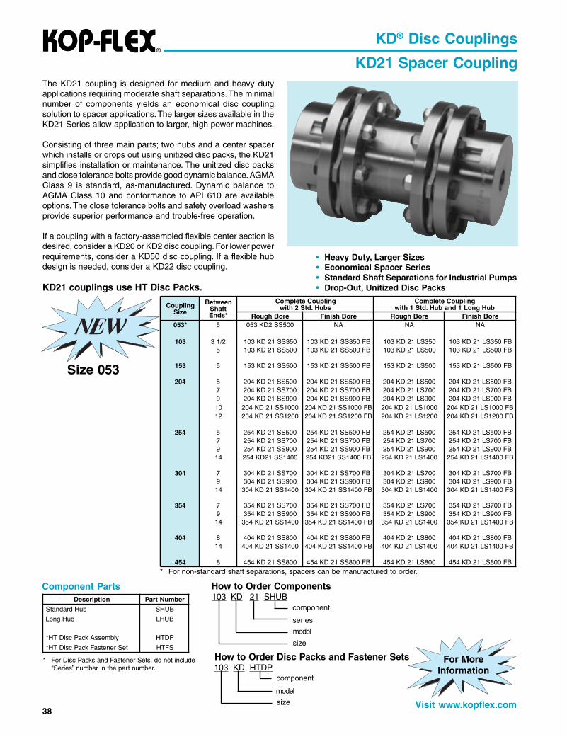
KD21 Spacer CouplingThe KD21 coupling is designed for medium and heavy dutyapplications requiring moderate shaft separations. The minimalnumber of components yields an economical disc couplingsolution to spacer applications. The larger sizes available in theKD21 Series allow application to larger, high power machines.
Consisting of three main parts; two hubs and a center spacerwhich installs or drops out using unitized disc packs, the KD21simplifies installation or maintenance. The unitized disc packsand close tolerance bolts provide good dynamic balance. AGMAClass 9 is standard, as-manufactured. Dynamic balance toAGMA Class 10 and conformance to API 610 are availableoptions. The close tolerance bolts and safety overload washersprovide superior performance and trouble-free operation.
If a coupling with a factory-assembled flexible center section isdesired, consider a KD20 or KD2 disc coupling. For lower powerrequirements, consider a KD50 disc coupling. If a flexible hubdesign is needed, consider a KD22 disc coupling.
KD21 couplings use HT Disc Packs.
Component Parts
• Heavy Duty, Larger Sizes• Economical Spacer Series• Standard Shaft Separations for Industrial Pumps• Drop-Out, Unitized Disc Packs
How to Order Components
* For non-standard shaft separations, spacers can be manufactured to order.
* For Disc Packs and Fastener Sets, do not include“Series” number in the part number.
How to Order Disc Packs and Fastener Sets
103 KD 21 SHUB
model
series
component
size
103 KD HTDP
size
component
model
noitpircseD rebmuNtraPbuHdradnatS BUHS
buHgnoL BUHL
ylbmessAkcaPcsiDTH* PDTH
teSrenetsaFkcaPcsiDTH* SFTH
gnilpuoCeziS
neewteBtfahS*sdnE
gnilpuoCetelpmoCsbuH.dtS2htiw
gnilpuoCetelpmoCbuHgnoL1dnabuH.dtS1htiw
eroBhguoR eroBhsiniF eroBhguoR eroBhsiniF*350 5 005SS2DK350 AN AN AN
Data based on min. “C” dimensions and maximum bores.See Balance Specifications page 23. Consult engineering for applications where speed exceed 75% of max. speed rating.
LONGHUB
STANDARDHUB
* Long hubs are available for sizes 103 to 454 only.
Note: "C" dimension = length of spacer plus (2) disc packs (including flat washers).
Note: Shaft separations longer than stock may be accomodated by using stock spacers and counterboring and overhanging long hubs to make up the difference.Shaft fit length should be equal to "E" or greater. Consult KOP-FLEX for more details.
40
Spacer Flange Data
KD® Disc Couplings
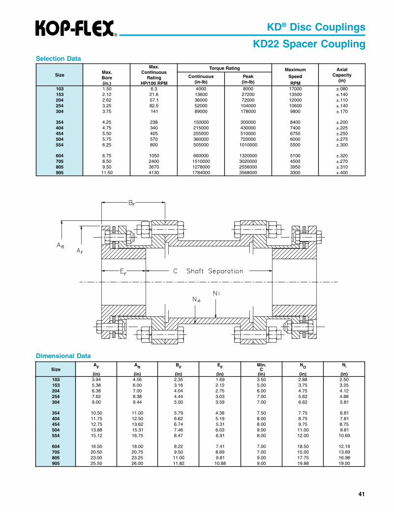
KD22 Spacer CouplingThe KD22 coupling is designed to be the most directreplacement for standard spacer style gear couplings andis meant for heavy duty applications where the flexiblesection must be located on the equipment shafts. Thepower capacity of the KD22 coupling is the highest in theindustry, allowing the easiest conversion from a lubricatedcoupling to a low maintenance disc coupling.
Consisting of three main parts, two flexible half couplingsand a center spacer which installs or drops out, the KD22simplifies installation or maintenance and allows theconnected equipment to be installed or removed keepingeach half coupling completely assembled. The unitizeddisc packs and close tolerance bolts provide gooddynamic balance. AGMA Class 8 is standard, asmanufactured. Dynamic balance to AGMA Class 9 andconformance to API 610 are available options.
The KD22 coupling employs standard gear couplingspacer flanges which can be used to provide standardelectrical insulation or shear cartridge features.
For other spacer designs, consider KD20 or KD21 disccouplings. For lower power requirements, consider a KD2disc coupling.
KD22 couplings use HT Disc Packs.
Complete KD22 Couplings are made to order. Contactyour local EPT representative to order.
• Heavy Duty, Larger Sizes• Flexible Shaft Hubs• Reduced Overhung Weight• High Power, Unitized Disc Packs
Component Parts
How to Order Hubs
* Flex Halves are designated by disc/spacer size,and include (1) disc pack and (1) disc packfastener set.
** For Disc Packs Components, do not include“Series” number in the part number.
How to Order Flex Halves
Note: KD10 Hubs are used on KD22 Couplings.
103 KD 10 SHUB
model
series
component
size
103/1.0 KD 42 FH
model
series
component
disc/spacer size
Note: KD42 Flex Halves are used on KD22Couplings.See Spacer Flange Data for sizes.
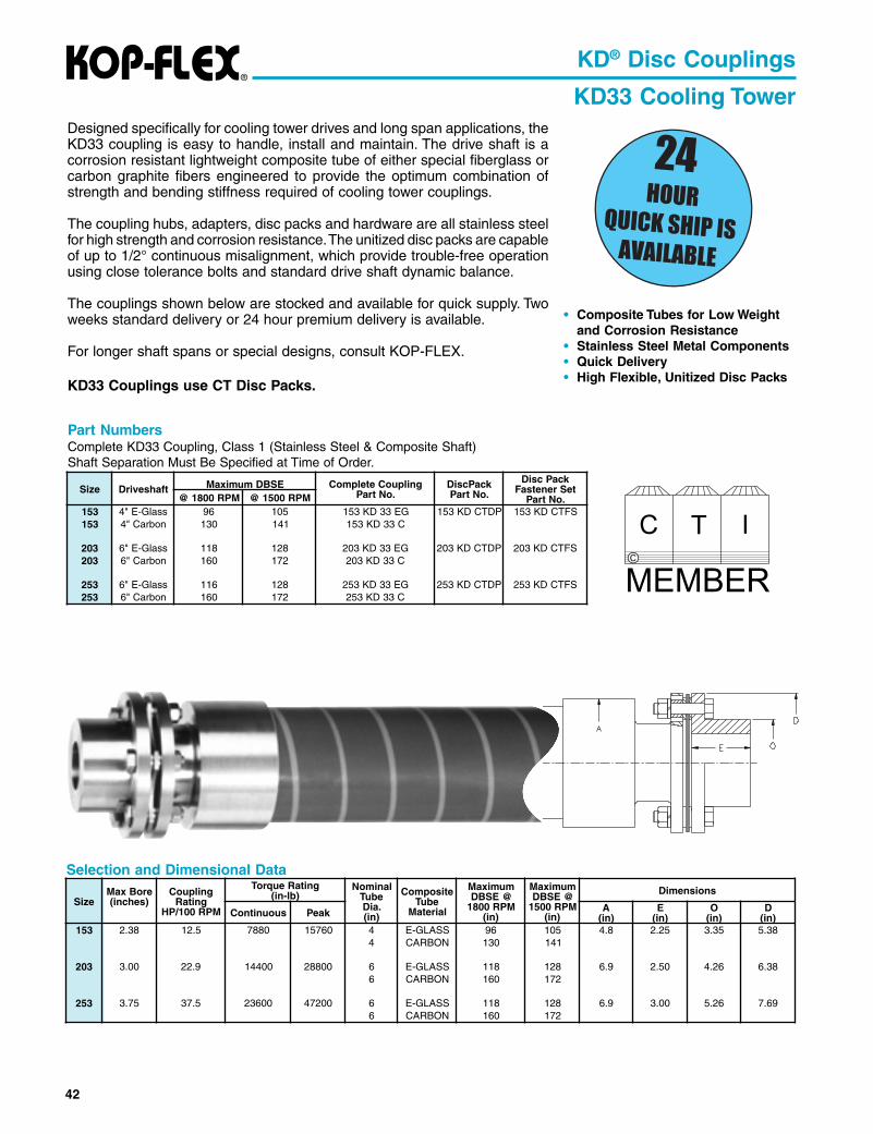
Part NumbersComplete KD33 Coupling, Class 1 (Stainless Steel & Composite Shaft)Shaft Separation Must Be Specified at Time of Order.
KD® Disc Couplings
KD33 Cooling TowerDesigned specifically for cooling tower drives and long span applications, theKD33 coupling is easy to handle, install and maintain. The drive shaft is acorrosion resistant lightweight composite tube of either special fiberglass orcarbon graphite fibers engineered to provide the optimum combination ofstrength and bending stiffness required of cooling tower couplings.
The coupling hubs, adapters, disc packs and hardware are all stainless steelfor high strength and corrosion resistance. The unitized disc packs are capableof up to 1/2° continuous misalignment, which provide trouble-free operationusing close tolerance bolts and standard drive shaft dynamic balance.
The couplings shown below are stocked and available for quick supply. Twoweeks standard delivery or 24 hour premium delivery is available.
For longer shaft spans or special designs, consult KOP-FLEX.
KD33 Couplings use CT Disc Packs.
• Composite Tubes for Low Weightand Corrosion Resistance
• Stainless Steel Metal Components• Quick Delivery• High Flexible, Unitized Disc Packs
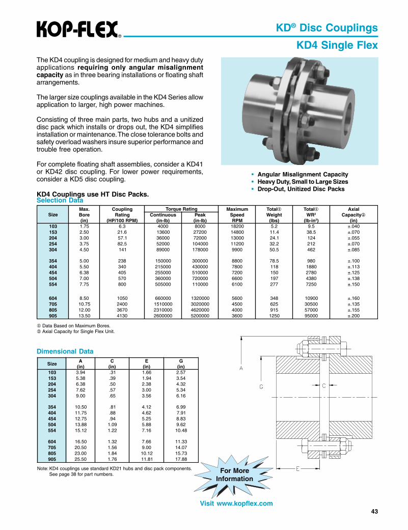
KD4 Single FlexThe KD4 coupling is designed for medium and heavy dutyapplications requiring only angular misalignmentcapacity as in three bearing installations or floating shaftarrangements.
The larger size couplings available in the KD4 Series allowapplication to larger, high power machines.
Consisting of three main parts, two hubs and a unitizeddisc pack which installs or drops out, the KD4 simplifiesinstallation or maintenance. The close tolerance bolts andsafety overload washers insure superior performance andtrouble free operation.
For complete floating shaft assemblies, consider a KD41or KD42 disc coupling. For lower power requirements,consider a KD5 disc coupling.
KD4 Couplings use HT Disc Packs.
Dimensional Data
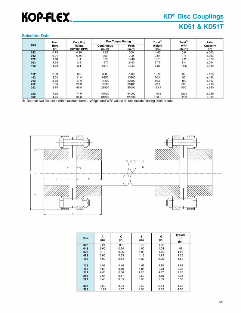
Selection Data
Data Based on Maximum Bores. Axial Capacity for Single Flex Unit.
• Angular Misalignment Capacity• Heavy Duty, Small to Large Sizes• Drop-Out, Unitized Disc Packs
Note: KD4 couplings use standard KD21 hubs and disc pack components.See page 38 for part numbers.
KD41 & KD41T Floating ShaftsThe KD41 coupling is designed for medium and heavyduty applications requiring longer shaft separations. Theminimal number of components yields an economical disccoupling solution to floating shaft applications. The largersize couplings available in the KD41 Series allowapplication to larger, high power machines.
The KD41 floating shaft coupling uses two single flexhalves in conjunction with a solid center shaft, whichinstalls or drops out simplifying installation ormaintenance. The unitized disc packs, close tolerancebolts and safety overload washers provide superiorperformance and trouble-free zero backlash operation.
For lighter weight or higher stiffness, a tubular floatingshaft design is available. The KD41T has all of the featuresof the KD41, but with a tubular shaft. For a directreplacement of a gear coupling floating shaft, consider aKD42 disc coupling. For a lower power application,consider the KD51 disc coupling.
KD41 Couplings use HT Disc Packs.
Dimensional Data
KD41
KD41T
• Heavy Duty, Larger Sizes• Economical Solid or Tubular Floating Shafts• Drop-Out, Unitized Disc Packs
Complete CouplingsComplete KD41 and KD41T Couplings are made toorder. Contact your local EPT representative to order.
* For Disc Pack Components, do not include“Series” number in part number.
How to Order Components
Note: KD21 Hubs are used for KD41 and KD41T floating shaft couplings.
103 KD HTDP
size
component
model
Ordering Instructions: When ordering floating shaft couplings, be sure to include hp and rpm, shaft separation, and equipment shaftsizes. Applications with very large shaft separations and/or high speeds may require tubular floating shaftsdue to lateral critical speed considerations.
Important: Care must be exercised in proper selection of any shaft coupling. The Users must assure themselves that the design ofthe hub to shaft connection is adequate for the duty intended.
Data for two flex units with maximum bores. Weight and WR2 values do not include floating shaft or tube.
KD41
Ordering Instructions: When ordering floating shaft couplings, be sure to include hp and rpm, shaft separation, and equipment shaftsizes. Applications with very large shaft separations and/or high speeds may require tubular floating shafts dueto lateral critical speed considerations.
Important: Care must be exercised in proper selection of any shaft coupling. The Users must assure themselves that the design of thehub to shaft connection is adequate for the duty intended.
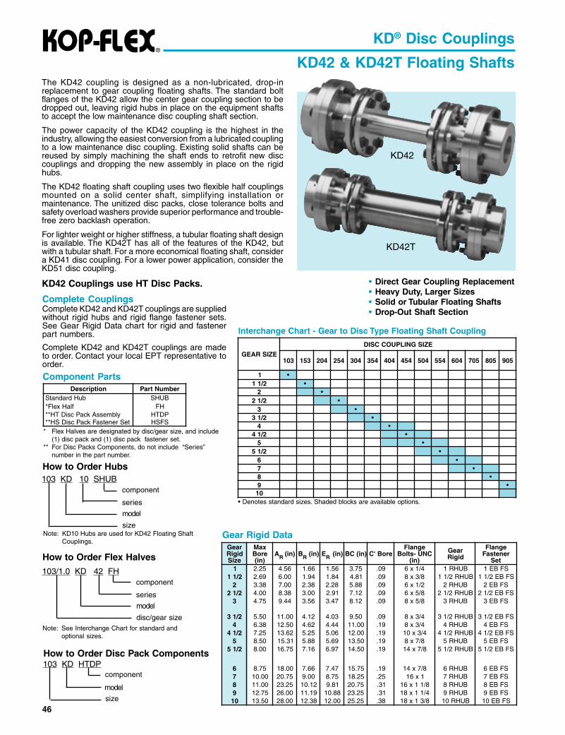
KD42 & KD42T Floating ShaftsThe KD42 coupling is designed as a non-lubricated, drop-inreplacement to gear coupling floating shafts. The standard boltflanges of the KD42 allow the center gear coupling section to bedropped out, leaving rigid hubs in place on the equipment shaftsto accept the low maintenance disc coupling shaft section.
The power capacity of the KD42 coupling is the highest in theindustry, allowing the easiest conversion from a lubricated couplingto a low maintenance disc coupling. Existing solid shafts can bereused by simply machining the shaft ends to retrofit new disccouplings and dropping the new assembly in place on the rigidhubs.
The KD42 floating shaft coupling uses two flexible half couplingsmounted on a solid center shaft, simplifying installation ormaintenance. The unitized disc packs, close tolerance bolts andsafety overload washers provide superior performance and trouble-free zero backlash operation.
For lighter weight or higher stiffness, a tubular floating shaft designis available. The KD42T has all of the features of the KD42, butwith a tubular shaft. For a more economical floating shaft, considera KD41 disc coupling. For a lower power application, consider theKD51 disc coupling.
KD42 Couplings use HT Disc Packs.
KD42
KD42T
• Direct Gear Coupling Replacement• Heavy Duty, Larger Sizes• Solid or Tubular Floating Shafts• Drop-Out Shaft Section
Component Parts
Gear Rigid Data
Complete CouplingsComplete KD42 and KD42T couplings are suppliedwithout rigid hubs and rigid flange fastener sets.See Gear Rigid Data chart for rigid and fastenerpart numbers.
Complete KD42 and KD42T couplings are madeto order. Contact your local EPT representative toorder.
Interchange Chart - Gear to Disc Type Floating Shaft Coupling
* Flex Halves are designated by disc/gear size, and include(1) disc pack and (1) disc pack fastener set.
** For Disc Packs Components, do not include “Series”number in the part number.
How to Order Hubs
How to Order Flex Halves
Note: KD10 Hubs are used for KD42 Floating ShaftCouplings.
103 KD 10 SHUB
model
series
component
size
Note: See Interchange Chart for standard andoptional sizes.
How to Order Disc Pack Components103 KD HTDP
size
component
model
103/1.0 KD 42 FH
model
series
component
disc/gear size
• Denotes standard sizes. Shaded blocks are available options.
Ordering Instructions: When ordering floating shaft couplings, be sure to include hp and rpm, shaft separation, and equipment shaftsizes. Applications with very large shaft separations and/or high speeds may require tubular floating shafts dueto lateral critical speed considerations.
Important: Care must be exercised in proper selection of any shaft coupling. The Users must assure themselves that the design of thehub to shaft connection is adequate for the duty intended.
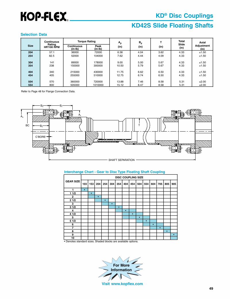
KD42S Slide Floating ShaftsThe power capacity of the KD42 coupling is the highestin the industry, allowing the easiest conversion from alubricated coupling to a low maintenance disc coupling.Existing solid shafts can be reused by simply machiningthe shaft ends to retrofit new disc couplings and droppingthe new assembly in place on the rigid hubs.
The KD42 floating shaft coupling uses two flexible halfcouplings mounted on a solid center shaft, simplifyinginstallation or maintenance. The unitized disc packs,close tolerance bolts and safety overload washersprovide superior performance and trouble-free near zerobacklash operation.
• Direct Gear Coupling Replacement• Heavy Duty, Larger Sizes• Drop-Out Telescopic Shaft Section• Stocked Standard Universal Joint
Slide (Telescopic) Assembly• Splines Coated with Special Polymide
6 Coating for Reduced Maintenance
Gear Rigid Data
Complete CouplingsComplete KD42 and KD42S couplings aresupplied without rigid hubs and rigid flangefastener sets. See Gear Rigid Data chart forrigid and fastener part numbers.
Complete KD42 and KD42S couplings aremade to order. Contact your local EPTrepresentative to order.
For lighter weight or higher stiffness, a tubular floatingshaft design is available. The KD42S has all of thefeatures of the KD42, but with a tubular shaft.
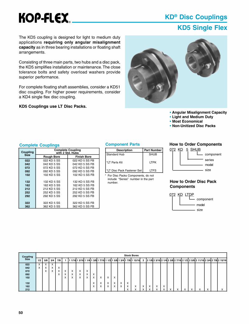
The KD5 coupling is designed for light to medium dutyapplications requiring only angular misalignmentcapacity as in three bearing installations or floating shaftarrangements.
Consisting of three main parts, two hubs and a disc pack,the KD5 simplifies installation or maintenance. The closetolerance bolts and safety overload washers providesuperior performance.
For complete floating shaft assemblies, consider a KD51disc coupling. For higher power requirements, considera KD4 single flex disc coupling.
KD5 Couplings use LT Disc Packs.
KD® Disc Couplings
KD5 Single Flex
• Angular Misalignment Capacity• Light and Medium Duty• Most Economical• Non-Unitized Disc Packs
Complete Couplings Component Parts How to Order Components
* For Disc Packs Components, do notinclude “Series” number in the partnumber.
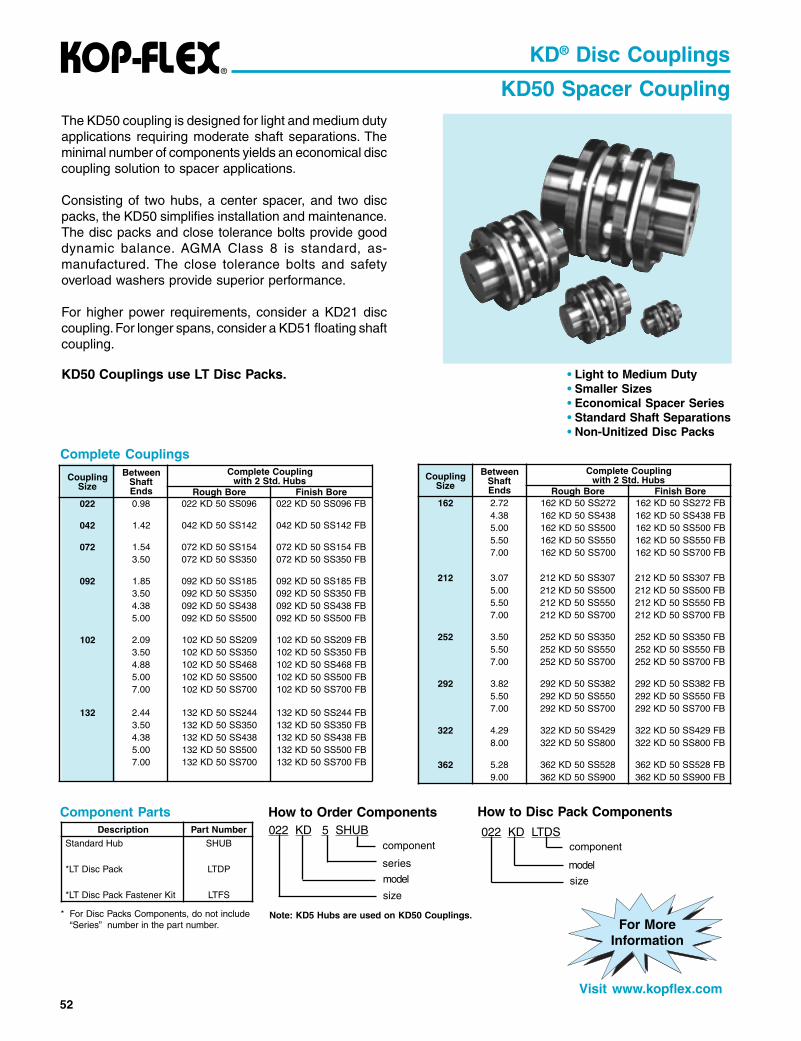
The KD50 coupling is designed for light and medium dutyapplications requiring moderate shaft separations. Theminimal number of components yields an economical disccoupling solution to spacer applications.
Consisting of two hubs, a center spacer, and two discpacks, the KD50 simplifies installation and maintenance.The disc packs and close tolerance bolts provide gooddynamic balance. AGMA Class 8 is standard, as-manufactured. The close tolerance bolts and safetyoverload washers provide superior performance.
For higher power requirements, consider a KD21 disccoupling. For longer spans, consider a KD51 floating shaftcoupling.
KD50 Couplings use LT Disc Packs.
KD® Disc Couplings
KD50 Spacer Coupling
• Light to Medium Duty• Smaller Sizes• Economical Spacer Series• Standard Shaft Separations• Non-Unitized Disc Packs
Complete Couplings
Component Parts How to Order Components
* For Disc Packs Components, do not include“Series” number in the part number.
220 42.2 45.2 22.0 69.0 97.0 62.1240 66.2 24.3 42.0 24.1 00.1 43.1270 91.3 45.3 62.0 45.1 00.1 58.1 X290 66.3 11.4 33.0 58.1 21.1 39.1 X X X201 90.4 37.4 44.0 90.2 23.1 63.2 X X X X
231 69.4 86.5 64.0 44.2 26.1 08.2 X X X X261 26.5 84.6 64.0 27.2 88.1 13.3 X X X X212 16.6 75.7 66.0 70.3 52.2 71.4 X X X252 46.7 05.8 76.0 05.3 05.2 56.4 X X292 34.8 28.9 58.0 28.3 00.3 93.5 X X
220 X X X240 X X X X270 X X X X X X X290 X X X X X X201 X X X X X X X X
231 X X X X X X261 X X X X X X X X X X X212 X X X X X X X X X X X X X
54
The KD51 & KD51T couplings aredesigned for light and medium dutyapplications requiring longer shaftseparations. The minimal number ofcomponents yields an economicaldisc coupling solution to floating shaftapplications.
The KD51 floating shaft coupling usestwo single flex halves in conjunctionwith a solid center shaft, which installsor drops out simplifying installation ormaintenance. The KD51T uses atubular floating shaft for lighter weight.The close tolerance bolts and safetyoverload washers provide superiorperformance.
For higher power applications,consider a KD41 floating shaft disccoupling.
KD51 Couplings useNon-Unitized LT Disc Packs.
KD® Disc Couplings
KD51& KD51T
• Light to Medium Duty• Smaller Sizes• Economical Floating Shaft Series• Non-Unitized Disc Packs
Complete CouplingsComplete KD51 and KD51T couplings are madeto order. Contact your local EPT representative toorder.
Component Parts How to Order Components
* For Disc Packs Components, do not include“Series” number in the part number.
How to Order Disc Pack Components
Note: KD5 Hubs are used on KD51 and KD51T Couplings.
These couplings are engineered to accommodate a broad range of demanding operatingconditions: boiler feed pumps, centrifugal and axial compressors, generator sets, test stands,gas and steam turbines, marine drives, etc.
The HP disc coupling is the preferred choice fordemanding turbomachinery applications. Superior qualityand a wide variety of standard and custom designs backedby unsurpassed engineering expertise make KOP-FLEXthe industry leader.
• Inherent fail-safe designs• KOPLON* coated flexible disc elements for maximum life• Factory assembled• Greatest reduced moment available• Dynamically balanced
High Performance Flexible Diaphragm CouplingsThe patented Flexible Diaphragm Coupling from KOP-FLEX® brand couplings transmits torquefrom the driving shaft via a rigid hub, then through a flexible diaphragm to a spacer. The diaphragmdeforms while transmitting this torque to accommodate misalignment. The spacer in turn drivesmatching components attached to the driven equipment. Outstanding design features include:
Stainless Steel• Inherently Low Windage Design• Conforms To API 671 Specifications
HIGH PERFORMANCE DISC COUPLINGS...Available In Four Standard Styles...Designed And Manufactured To Meet API 671 As Standard
High Performance Gear Couplings• Thousands in Service• Choose From Straight or Crowned Nitrided Gear Teeth,
Depending on your Application• Precision Lapped Teeth, if Required• Heat-treated Alloy Components
Size #6 Gear CouplingG.E. MS5001 Gas Turbine Driven
Compressor Train
Reduced MomentHigh Performance Disc Coupling
Size #5.5 MDM-Jdiaphragm coupling
Request a copy of Catalog KHP-00 or visit www.kop-flex.com
HIGH PERFORMANCE COUPLINGS
*KOPLON is a trademark of E. I. du Pont de Nemours and Company.This trade name, trademark and/or registered trademark is used herein for productcomparison purposes only, is the property of the respective owner and is not owned orcontrolled by Emerson Power Transmission Corporation (EPT). EPT does not represent orwarrant the accuracy of this document.