New Steady-Hand Eye Robot with Micro-Force Sensing for Vitreoretinal Surgery Ali ¨ Uneri, Marcin A. Balicki, James Handa, Peter Gehlbach, Russell H. Taylor, and Iulian Iordachita Abstract—In retinal microsurgery, surgeons are required to perform micron scale maneuvers while safely applying forces to the retinal tissue that are below sensory perception. Real- time characterization and precise manipulation of this delicate tissue has thus far been hindered by human limits on tool control and the lack of a surgically compatible endpoint sensing instrument. Here we present the design of a new generation, cooperatively controlled microsurgery robot with a remote center-of-motion (RCM) mechanism and an integrated custom micro-force sensing surgical hook. Utilizing the forces measured by the end effector, we correct for tool deflections and implement a micro-force guided cooperative control algorithm to actively guide the operator. Preliminary experiments have been carried out to test our new control methods on raw chicken egg inner shell membranes and to capture useful dynamic characteristics associated with delicate tissue manipulations. I. I NTRODUCTION Retinal microsurgery is one of the most challenging set of surgical tasks due to human sensory-motor limitations, the need for sophisticated and miniature instrumentation, and the inherent difficulty of performing micron scale motor tasks in a small and fragile environment. Surgical performance is further challenged by imprecise instruments, physiological hand tremor, poor visualization, lack of accessibility to some structures, patient movement, and fatigue from prolonged op- erations. The surgical instruments in retinal surgery are char- acterized by long, thin shafts (typically 0.5 mm to 0.7 mm in diameter) that are inserted through the sclera (the visible white wall of the eye). The forces exerted by these tools are often far below human sensory thresholds [1]. The surgeon therefore must rely on visual cues to avoid exerting excessive forces on the retina. All of these factors contribute to surgical errors and complications that may lead to vision loss. Although robotic assistants such as da Vinci [2] have been widely deployed for laparoscopic surgery, systems targeted at microsurgery are at the present time still at the research stage. Proposed systems include teleoperation systems [3], [4], freehand active tremor-cancellation systems [5], [6], and cooperatively controlled hand-over-hand systems such as the Johns Hopkins “Steady Hand” robots [7], [8]. In steady-hand control, the surgeon and robot both hold the surgical tool; the robot senses forces exerted by the surgeon on the tool handle, and moves to comply, filtering out any tremor. For retinal Manuscript received April 9, 2010. This work was supported in part by the U.S. National Science Foundation under Cooperative Agreement ERC9731478, in part by the National Institutes of Health under BRP 1 R01 EB 007969-01 A1, and in part by Johns Hopkins internal funds. The authors are affiliated with the Center for Computer-Integrated Surgical Systems and Technology (CISST ERC) at The Johns Hopkins University, 3400 N. Charles Street, Baltimore, Maryland 21218 USA. Corresponding Author: Iulian Iordachita ([email protected], 410-516-3839). microsurgery, the tools typically pivot at the sclera insertion point, unless the surgeon wants to move the eyeball. This pivot point may either be enforced by a mechanically con- strained remote center-of-motion (RCM) [7] or software [8]. Interactions between the tool shaft and sclera complicate both the control of the robot and measurement of tool-to-retina forces. Fig. 1. Retinal surgery research platform. In earlier work, we reported the development of an ex- tremely sensitive (0.25 mN resolution) force sensor mounted on the tool shaft, distal to the sclera insertion point [9]. This proved to be a straightforward way to measure tool- tissue forces while diminishing interference from tool-sclera forces [10]. Further, Kumar and Berkelman used endpoint micro-force sensors in surgical applications, where a force scaling cooperative control method generates robot response based on the scaled difference between tool-tissue and tool- hand forces [11], [12], [13]. In other recent work [8], we reported a first-generation steady-hand robot (Eye Robot 1) specifically designed for vitreoretinal surgery. It was success- fully used in ex-vivo robot assisted vessel cannulation exper- iments, but was found to be ergonomically limiting [14]. In this paper, we report the development of the next gen- eration vitreoretinal surgery platform (Eye Robot 2), a novel augmented cooperative control method, and present experi- ments utilizing this system. Eye Robot 2 incorporates both a significantly improved manipulator and an integrated micro- force sensing tool. Ultimately, we are interested in using this platform to assess soft tissue behavior through vitreoretinal tissue manipulation. This information may enhance surgical technique by revealing factors that contribute to successful surgical results, and minimize unwanted complications. This capability may also be applied to the dynamic updating of !"#$%%&’()* #, -.% /010 2"& 3444 567 8 49:7 3(-%"(;-’#(;< =#(,%"%($% #( :’#>%&’$;< 5#?#-’$* ;(& :’#>%$.;-"#(’$*@ A.% B(’C%"*’-D #, A#ED#@ A#ED#@ F;G;(@ 7%G-%>?%" /HI/J@ /010 JKLI1IM/MMIKK0JILN10NO/HP00 Q/010 3444 L1M
Transcript
New Steady-Hand Eye Robot with Micro-Force Sensing
for Vitreoretinal Surgery
Ali Uneri, Marcin A. Balicki, James Handa, Peter Gehlbach, Russell H. Taylor, and Iulian Iordachita
Abstract— In retinal microsurgery, surgeons are required to
perform micron scale maneuvers while safely applying forces
to the retinal tissue that are below sensory perception. Real-
time characterization and precise manipulation of this delicate
tissue has thus far been hindered by human limits on tool
control and the lack of a surgically compatible endpoint
sensing instrument. Here we present the design of a new
generation, cooperatively controlled microsurgery robot with a
remote center-of-motion (RCM) mechanism and an integrated
custom micro-force sensing surgical hook. Utilizing the forces
measured by the end effector, we correct for tool deflections and
implement a micro-force guided cooperative control algorithm
to actively guide the operator. Preliminary experiments have
been carried out to test our new control methods on raw chicken
egg inner shell membranes and to capture useful dynamic
characteristics associated with delicate tissue manipulations.
I. INTRODUCTION
Retinal microsurgery is one of the most challenging set ofsurgical tasks due to human sensory-motor limitations, theneed for sophisticated and miniature instrumentation, and theinherent difficulty of performing micron scale motor tasksin a small and fragile environment. Surgical performance isfurther challenged by imprecise instruments, physiologicalhand tremor, poor visualization, lack of accessibility to somestructures, patient movement, and fatigue from prolonged op-erations. The surgical instruments in retinal surgery are char-acterized by long, thin shafts (typically 0.5mm to 0.7mm
in diameter) that are inserted through the sclera (the visiblewhite wall of the eye). The forces exerted by these tools areoften far below human sensory thresholds [1]. The surgeontherefore must rely on visual cues to avoid exerting excessiveforces on the retina. All of these factors contribute to surgicalerrors and complications that may lead to vision loss.
Although robotic assistants such as da Vinci [2] have beenwidely deployed for laparoscopic surgery, systems targetedat microsurgery are at the present time still at the researchstage. Proposed systems include teleoperation systems [3],[4], freehand active tremor-cancellation systems [5], [6], andcooperatively controlled hand-over-hand systems such as theJohns Hopkins “Steady Hand” robots [7], [8]. In steady-handcontrol, the surgeon and robot both hold the surgical tool; therobot senses forces exerted by the surgeon on the tool handle,and moves to comply, filtering out any tremor. For retinal
Manuscript received April 9, 2010. This work was supported in partby the U.S. National Science Foundation under Cooperative AgreementERC9731478, in part by the National Institutes of Health under BRP 1 R01EB 007969-01 A1, and in part by Johns Hopkins internal funds. The authorsare affiliated with the Center for Computer-Integrated Surgical Systemsand Technology (CISST ERC) at The Johns Hopkins University, 3400 N.Charles Street, Baltimore, Maryland 21218 USA. Corresponding Author:Iulian Iordachita ([email protected], 410-516-3839).
microsurgery, the tools typically pivot at the sclera insertionpoint, unless the surgeon wants to move the eyeball. Thispivot point may either be enforced by a mechanically con-strained remote center-of-motion (RCM) [7] or software [8].Interactions between the tool shaft and sclera complicate boththe control of the robot and measurement of tool-to-retinaforces.
Fig. 1. Retinal surgery research platform.
In earlier work, we reported the development of an ex-tremely sensitive (0.25mN resolution) force sensor mountedon the tool shaft, distal to the sclera insertion point [9].This proved to be a straightforward way to measure tool-tissue forces while diminishing interference from tool-scleraforces [10]. Further, Kumar and Berkelman used endpointmicro-force sensors in surgical applications, where a forcescaling cooperative control method generates robot responsebased on the scaled difference between tool-tissue and tool-hand forces [11], [12], [13]. In other recent work [8], wereported a first-generation steady-hand robot (Eye Robot 1)specifically designed for vitreoretinal surgery. It was success-fully used in ex-vivo robot assisted vessel cannulation exper-iments, but was found to be ergonomically limiting [14].
In this paper, we report the development of the next gen-eration vitreoretinal surgery platform (Eye Robot 2), a novelaugmented cooperative control method, and present experi-ments utilizing this system. Eye Robot 2 incorporates both asignificantly improved manipulator and an integrated micro-force sensing tool. Ultimately, we are interested in using thisplatform to assess soft tissue behavior through vitreoretinaltissue manipulation. This information may enhance surgicaltechnique by revealing factors that contribute to successfulsurgical results, and minimize unwanted complications. Thiscapability may also be applied to the dynamic updating of
virtual fixtures in robot assisted manipulation. All of thesefeatures could provide strategies that will revolutionize howvitreoretinal surgery is performed and taught.
We present a novel method called micro-force guided
cooperative control that assists the operator in manipulatingtissue in the direction of least resistance. This function hasthe potential to aid in challenging retinal membrane peelingprocedures that require a surgeon to delicately delaminatefragile tissue that is susceptible to hemorrhage and tearingdue to undesirable forces. Preliminary experiments with rawchicken eggs demonstrate the capabilities of our platform incharacterizing the delicate inner shell membrane and test ournew control algorithm in peeling operations.
II. EYE ROBOT: VERSION 2
Fig. 2. CAD model of ER2, and close up view of its end effector.
Eye Robot 2 (ER2) is an intermediate design towards astable and fully capable microsurgery research platform forthe evaluation and development of robot-assisted microsur-gical procedures and devices (Fig. 1,2). Through extensiveuse of Eye Robot 1 (ER1), we have identified a number oflimitations that are addressed in this new version.
Robot
Retina
ScleraEntry Point
60˚
ø 25.4 mm
Lens
12 mm}
4 mm
}
Fig. 3. Geometry study of tool motion through the sclera.
We increased the tool rotation range of the tilt axis to ±60◦
in order to cover a variety of user ergonomic preferences andextend the functionality of the robot for different tests andprocedures. A geometric study of the eye (Fig. 3) reveals that
the ±30◦ tool rotation limit of ER1 theoretically satisfies
the necessary range of motion of the tool inside the eye.However, this required exact positioning of the robot relativeto the skull, which is not always practical or even feasible.
ER1 uses a slider-crank mechanism (Fig. 4a) for tiltrotation, which is a compact design with minimal connec-tions and joints. It relies on software algorithm to pro-grammatically constrain the tool axis to always intersect thesclerotomy opening on the eye [8]. Although this “VirtualRCM” was successful at constraining the motion, it wasobserved to introduce large concurrent joint velocities inthe Cartesian stages. This is an undesirable behavior fora steady-hand robot. Here we have implemented a parallelsix-bar mechanism (Fig. 4b) that mechanically provides theisocentric motion, which minimizes the translation of XYZstages.
(a) Slider-crank.
(b) Parallel six-bar.
Fig. 4. Tilting mechanisms of ER1 (a) and ER2 (b).
The lead-screws of ER1 were chosen to eliminate back-lash, however through extensive use, we have found them tobe unreliable, requiring regular maintenance and recalibra-tion. The new design incorporates robust ball-screw linearstages that have high accuracy and precision. To further min-imize the deflection error induced through user interaction,the extending carbon fiber arm was replaced by a more rigidtilt mechanism design with a rectangular profile.
A. Robot Components
The resulting robot manipulator consists of four subassem-blies: 1) XYZ linear stages for translation; 2) a rotary stagefor rolling 3) a tilting mechanism with a mechanical RCMand 4) a tool adaptor with a handle force sensor.
Parker Daedal 404XR linear stages (Parker HannifinCorp., Rohnert Park, CA) with precise ball-screw are used toprovide 100mm travel along each axis with a bidirectionalrepeatability of 3 µm and positioning resolution of 1 µm.
L1R
A Newport URS 100B rotary stage (Newport Corp., Irvine,CA) is used for rolling, with a resolution of 0.0005◦ andrepeatability of 0.0001◦. A THK KR15 linear stage (THKAmerica Inc., Schaumburg, IL) with travel of 100mm andrepeatability of ±3 µm is used to provide tilting motion.The last active joint is a custom-designed RCM mechanism.A 6-DOF ATI Nano17 force/torque sensor (ATI IndustrialAutomation, Apex, NC) is mounted between the RCM andthe tool handle. Assembly specifications are presented inTab. I.
Specification Value
XYZ motion ±50mm
roll/tilt motion ±60◦
tool tip speed during approach 10mms−1
insertion 5mms−1
manipulation <1mms−1
handle sensor force range/res 0N to 5N (0.003N)
handle sensor torque range/res 0Nmm to 0.12Nmm (0.015Nmm)
TABLE IER2 ASSEMBLY SPECIFICATIONS.
The new robot software is based on the CISST SurgicalAssistant Workstation (SAW); a modular framework that pro-vides multithreading, networking, data logging and standarddevice interfaces [15]. It enables rapid system prototypingby simplifying integration of new devices and smart toolsinto the systems.
B. Integrated Tip Force Sensor
ER2 is theoretically designed to achieve micron position-ing accuracy. However, in practice, realizing this is greatlyaffected by the flexibility of the end effector, i.e. the surgicaltool. The unknown interaction forces at the tool tip resultin the deflection of the tool itself, which inherently affectsthe robot’s positioning performance. Measuring these forcesdirectly allows us to compensate for this deformation. We canalso integrate the real-time end-point sensing in intelligentcontrol schemes with safety measures to minimize the risksassociated with microsurgical procedures.
In related research, fiber Bragg grating (FBG) sensorswere chosen to achieve high resolution force measurementsat the tip of a long thin tube [16]. FBGs are opticalsensors capable of detecting changes in force, pressure andacceleration, without interference from electrostatic, electro-magnetic or radio frequency sources. The inherent design istheoretically temperature insensitive, but due to fabricationimperfections, temperature effects may be a factor. In suchcase it can be minimized by proper calibration and biasing.
We have built a 2-axis hooked instrument (Fig. 5) pre-sented in [9] that incorporates three optical fibers in a 0.5mm
diameter wire with a hooked tip. Based on the axial straindue to tool bending, the instrument senses forces at the tipin the transverse plane, with a sensitivity of 0.25mN in therange of 0mN to 60mN.
FBG Sensors
fyfx
Fig. 5. Tool with FBG force sensors attached, inserted through a sclerotomyopening.
The instrument is rigidly attached to the handle of ER2and is calibrated in order to transform it into the robotcoordinates. Samples are acquired from the FBG interrogatorat 2 kHz over a TCP/IP local network, and processed usingsoftware based on the same SAW framework.
III. METHODS
A. Tool Deflection Correction
In order to address the issue of flexibility at the end effec-tor we first characterized the deflection of the tool (Fig. 6a).The robot was translated 2mm laterally, pushing the tool tipagainst a rigid surface. The corresponding reaction force isdisplayed in Fig. 6b.
m=13.76
(a) Testing.
Robot Position
Tip Force
Tooltip Position
(b) Calibration.
Fig. 6. Reaction force due to tool deflection for 2mm travel. Note thatthe initial robot position is ∼0.4mm from the rigid surface.
The resulting response is linear and suggests a tool stiff-ness of 13.76Nm
−1. This constant (kt) is used to correct
L1H
for the deformation in the following fashion.
∆x = ftx/kt (1)∆y = fty/kt (2)
∆z = lt −��
l2t −∆x2 +
�l2t −∆y2
�(3)
where ft is the force at the tool tip and lt is the tool length.Since the amount of correction along the z-axis (∆z) is twoorders of magnitude smaller than transverse plane correctionwe roughly approximate the tool as a rigid body pivotingaround its base.
B. Constant Force Mode
This mode is used to command the robot to exert a desiredconstant force at the tool tip.
Θ = J−1t kp(fd − ft) (4)
where the error between the desired force fd and tip forceft is scaled by a proportional gain kp and multiplied by theinverse Jacobian of the end effector to generate robot jointvelocities.
C. Micro-force Guided Cooperative Control
Complications in vitreoretinal surgery may result fromexcess and/or incorrect application of forces to ocular tissue.Current practice requires the surgeon to keep operativeforces low and safe through slow and steady maneuvering.The surgeon must also rely solely on visual feedback thatcomplicates the problem, as it takes time to detect, assessand then react to the faint cues; a task especially difficult fornovice surgeons.
Our cooperative control [8] was therefore “augmented”using the real-time information from the tool tip force sensorto gently guide the operator towards lower forces in a peelingtask. The method can be analyzed in two main componentsas described below.
fh
ft
membrane
shelltear
potential trajectory
Fig. 7. Figure depicting a peeling process, with associated forces.
a) Global Force Limiting: This first layer of controlenforces a global limit on the forces applied to the tissueat the robot tool tip. Setting a maximum force fmax, thelimiting force flim on each axis would conventionally bedefined as
flim = fmaxrt, rt = |ft|/�ft� (5)
However, this approach has the disadvantage of halting allmotion when the tip force reaches the force limit, i.e. theoperator has to back up the robot in order to apply a forcein other directions. Distributing the limit with respect to thehandle input forces
flim = fmaxrh, rh = |fh|/�fh� (6)
gives more freedom to the operator, allowing him/her toexplore alternative directions (i.e. search for maneuvers thatwould generate lower tip forces) even when ft is at its limit.Considering the governing control law,
x = kpfh (7)
We apply the limit as follows;
xlim = x
�flim − |ft|
llim
�(8)
Thus Cartesian velocity is proportionally scaled with respectto current tip force, where a virtual spring of length llim isused to ensure stability at the limit boundary.
b) Local Force Minimization: The second layer is toguide the operator in order to prevent reaching the limit inthe first place. This is achieved by actively biasing the tooltip motion towards the direction of lower resistance. Theratio rt is used to update the operator input in the followingfashion
xmin = kp(1− rtsmin)fh (9)
where smin is the sensitivity of minimization that sets theratio of the handle force to be locally minimized. Note thatsmin = 0% implies that the operator is not able to overridethe guided behavior.
Finally, for extra safety we also detect if either sensor isengaged, e.g. if the operator is not applying any force at thehandle (< 0.1N), the robot minimizes ft by “backing up”.
x = kpft (10)
Algorithm 1 Micro-force guided cooperative control.if handle is not engaged then
do 10else if tip is engaged and tip is opposing handle then
do 9if tip is close to limit then
do 8end if
else
do 7end if
L1K
IV. EXPERIMENTS AND RESULTS
A series of experiments have been performed on theinner shell membrane of raw chicken eggs with the aim ofidentifying and controlling the forces associated with peelingoperations (Fig. 8). We routinely use this membrane in ourlaboratory as a surrogate for an epiretinal membrane.
Fig. 8. Setup for peeling experiments using raw eggs.
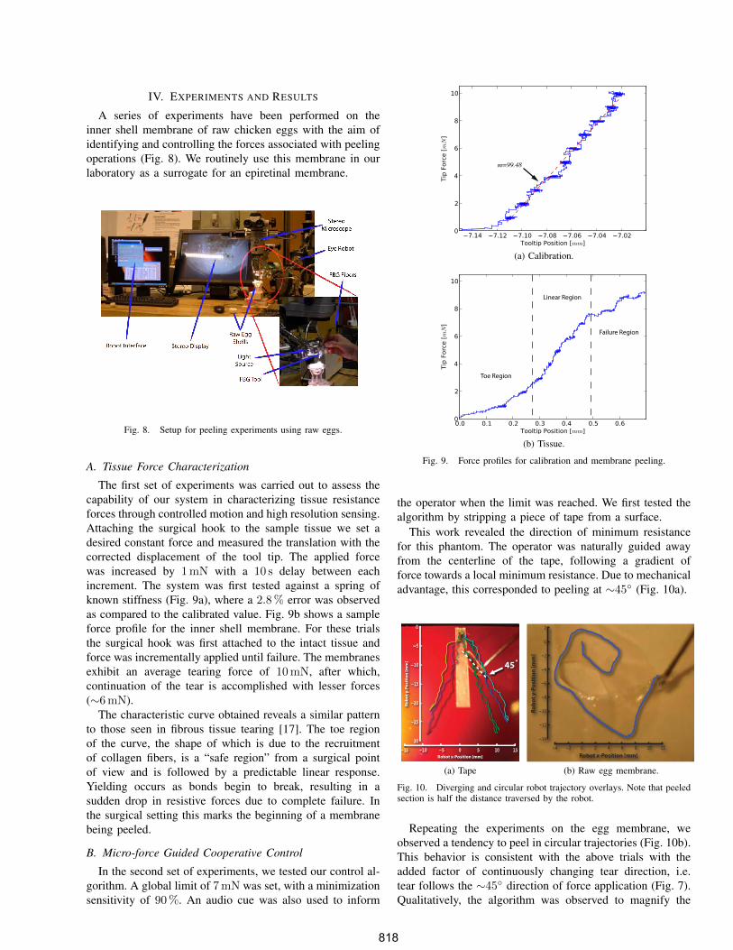
A. Tissue Force Characterization
The first set of experiments was carried out to assess thecapability of our system in characterizing tissue resistanceforces through controlled motion and high resolution sensing.Attaching the surgical hook to the sample tissue we set adesired constant force and measured the translation with thecorrected displacement of the tool tip. The applied forcewas increased by 1mN with a 10 s delay between eachincrement. The system was first tested against a spring ofknown stiffness (Fig. 9a), where a 2.8% error was observedas compared to the calibrated value. Fig. 9b shows a sampleforce profile for the inner shell membrane. For these trialsthe surgical hook was first attached to the intact tissue andforce was incrementally applied until failure. The membranesexhibit an average tearing force of 10mN, after which,continuation of the tear is accomplished with lesser forces(∼6mN).
The characteristic curve obtained reveals a similar patternto those seen in fibrous tissue tearing [17]. The toe regionof the curve, the shape of which is due to the recruitmentof collagen fibers, is a “safe region” from a surgical pointof view and is followed by a predictable linear response.Yielding occurs as bonds begin to break, resulting in asudden drop in resistive forces due to complete failure. Inthe surgical setting this marks the beginning of a membranebeing peeled.
B. Micro-force Guided Cooperative Control
In the second set of experiments, we tested our control al-gorithm. A global limit of 7mN was set, with a minimizationsensitivity of 90%. An audio cue was also used to inform
m=99.48
(a) Calibration.
Toe Region
Linear Region
Failure Region
(b) Tissue.
Fig. 9. Force profiles for calibration and membrane peeling.
the operator when the limit was reached. We first tested thealgorithm by stripping a piece of tape from a surface.
This work revealed the direction of minimum resistancefor this phantom. The operator was naturally guided awayfrom the centerline of the tape, following a gradient offorce towards a local minimum resistance. Due to mechanicaladvantage, this corresponded to peeling at ∼45
◦ (Fig. 10a).
Robot x-Position [mm]
Robo
t y-P
ositi
on [m
m] 45!
(a) Tape
Robot x-Position [mm]
Robo
t y-P
ositi
on [m
m]
(b) Raw egg membrane.
Fig. 10. Diverging and circular robot trajectory overlays. Note that peeledsection is half the distance traversed by the robot.
Repeating the experiments on the egg membrane, weobserved a tendency to peel in circular trajectories (Fig. 10b).This behavior is consistent with the above trials with theadded factor of continuously changing tear direction, i.e.tear follows the ∼45
◦ direction of force application (Fig. 7).Qualitatively, the algorithm was observed to magnify the
L1L
perception of tip forces lateral to the operator’s desiredmotion.
Upon reaching the force limit the operator exploredaround the boundary in search of points of lower resistancethat would enable continuation of peel. This was achievedsmoothly without requiring the operator to back up, asthe limits on axes were redistributed based on operator’sapplication of handle force.
V. DISCUSSION AND CONCLUSION
We have designed, built and tested a platform for vitreo-retinal surgery, on which we developed a novel cooperativecontrol method that assists the operator in manipulatingtissue within defined force limits. Using the system, wehave identified basic tissue force profiles in egg inner shellmembranes, which we then incorporated as input into ourcontrol algorithm.
The new generation system fulfills the function of simulat-ing and evaluating microsurgical procedures to increase ourunderstanding of the clinical requirements in microsurgicaltasks. It also serves as a robot-assisted development test-bench for a multitude of smart tools, including but notlimited to force sensing, optical coherence tomography, andspectroscopy modalities. Although we have incorporatedlessons learned from the previous version, we are contin-uously improving ER2 towards a stable, fully capable andclinically compatible microsurgery assistance robot. We areredesigning the tool holder to accommodate quick exchangeof a variety of instruments, and adding an encoder to therotational passive joint of the tool. This would enable theuse of more complex instruments like graspers, and tracktheir pose in 6 DOF.
We have found that 2 DOF tool tip force sensing wasadequate for the predefined manipulation tasks used in ourcontrolled experimental setup. However, a 3 DOF forcesensor will be required for interaction in less constrainedmaneuvers on more complex phantoms. The methods pre-sented here can easily be extended to make use of the extradegree of sensing and expand their range of applications.
Our micro-force guided cooperative control method wassuccessful in enforcing force limits, while assisting the oper-ator in achieving the desired goal. According to our surgeonco-authors, the circular pattern obtained in egg membranepeeling resembled standard surgical peeling techniques theyemploy, e.g. capsulorhexis maneuver during opening of theanterior capsule for cataract surgery. Further assessment ofthis comparison could help us better understand the underly-ing principles of such surgical methods, eventually helpingus to improve their performance.
The presented experiments with raw eggs demonstratethe potential capability of our platform for in-vivo analysisof tissue properties. Further information on tissue variationresulting from instantaneous reaction forces may be requiredto fully predict tissue behavior. These data will be funda-mental to the design of intelligent robot control methods.The dynamic properties may help us to identify pathological
signatures in target surgical tissue. More importantly suchdata can be used in training simulations for novice surgeons,especially to correlate the visual cues to quantifiable tissuebehaviors.
REFERENCES
[1] P. Gupta, P. Jensen, and E. de Juan, “Surgical forces and tactileperception during retinal microsurgery,” Medical Image Computing
and Computer-Assisted Intervention (MICCAI), pp. 1218–1225, 1999.[2] G. Guthart and J. Salisbury, J.K., “The intuitive telesurgery system:
overview and application,” in IEEE ICRA, vol. 1, 2000, pp. 618–621.[3] T. Nakano, N. Sugita, T. Ueta, Y. Tamaki, and M. Mitsuishi, “A
parallel robot to assist vitreoretinal surgery,” International Journal of
Computer Assisted Radiology and Surgery (IJCARS), vol. 4, no. 6, pp.517–26, Nov 2009.
[4] W. Wei, R. Goldman, N. Simaan, H. Fine, and S. Chang, “Designand theoretical evaluation of micro-surgical manipulators for orbitalmanipulation and intraocular dexterity,” in IEEE ICRA, Apr 2007, pp.3389–3395.
[5] C. Riviere, W. T. Ang, and P. Khosla, “Toward active tremor cancelingin handheld microsurgical instruments,” IEEE ICRA, vol. 19, no. 5,pp. 793–800, Oct 2003.
[6] U.-X. Tan, W. T. Latt, C. Y. Shee, and W. T. Ang, “Design anddevelopment of a low-cost flexure-based hand-held mechanism formicromanipulation,” in IEEE ICRA, May 2009, pp. 4350–4355.
[7] R. Taylor, P. Jensen, L. Whitcomb, A. Barnes, R. Kumar,D. Stoianovici, P. Gupta, Z. Wang, E. deJuan, and L. Kavoussi, “Asteady-hand robotic system for microsurgical augmentation,” MICCAI,pp. 1031–1041, 1999.
[8] B. Mitchell, J. Koo, M. Iordachita, P. Kazanzides, A. Kapoor, J. Handa,G. Hager, and R. Taylor, “Development and application of a newsteady-hand manipulator for retinal surgery,” in IEEE ICRA, Apr 2007,pp. 623–629.
[9] I. Iordachita, Z. Sun, M. Balicki, J. Kang, S. Phee, J. Handa,P. Gehlbach, and R. Taylor, “A sub-millimetric, 0.25 mn resolutionfully integrated fiber-optic force-sensing tool for retinal microsurgery,”International Journal of Computer Assisted Radiology and Surgery
(IJCARS), vol. 4, no. 4, pp. 383–390, Jun 2009.[10] A. Jagtap and C. Riviere, “Applied force during vitreoretinal micro-
surgery with handheld instruments,” in IEEE International Conference
on Engineering in Medicine and Biology Society (IEMBS), vol. 1, Sep2004, pp. 2771–2773.
[11] P. Berkelman, L. Whitcomb, R. Taylor, and P. Jensen, “A miniaturemicrosurgical instrument tip force sensor for enhanced force feedbackduring robot-assisted manipulation,” IEEE ICRA, vol. 19, no. 5, pp.917–921, Oct 2003.
[12] R. Kumar, P. Berkelman, P. Gupta, A. Barnes, P. Jensen, L. Whitcomb,and R. Taylor, “Preliminary experiments in cooperative human/robotforce control for robot assisted microsurgical manipulation,” in IEEE
International Conference on Robotics and Automation (ICRA), vol. 1,2000, pp. 610–617.
[13] P. J. Berkelman, D. L. Rothbaum, J. Roy, S. Lang, L. L. Whitcomb,G. D. Hager, P. S. Jensen, E. d. Juan, R. H. Taylor, and J. K. Niparko,“Performance evaluation of a cooperative manipulation microsurgicalassistant robot applied to stapedotomy,” in MICCAI. London, UK:Springer-Verlag, 2001, pp. 1426–1429.
[14] I. Fleming, M. Balicki, J. Koo, I. Iordachita, B. Mitchell, J. Handa,G. Hager, and R. Taylor, “Cooperative robot assistant for retinalmicrosurgery,” MICCAI, pp. 543–550, 2008.
[15] B. Vagvolgyi, S. DiMaio, A. Deguet, P. Kazanzides, R. Kumar, C. Has-ser, and R. Taylor, “The Surgical Assistant Workstation: a softwareframework for telesurgical robotics research,” in MICCAI Workshop
on Systems and Architectures for Computer Assisted Interventions,Midas Journal: http://hdl.handle.net/10380/1466, Sep 2008.
[16] Z. Sun, M. Balicki, J. Kang, J. Handa, R. Taylor, and I. Iordachita,“Development and preliminary data of novel integrated optical micro-force sensing tools for retinal microsurgery,” in IEEE ICRA, May 2009,pp. 1897–1902.
[17] E. Gentleman, A. N. Lay, D. A. Dickerson, E. A. Nauman, G. A.Livesay, and K. C. Dee, “Mechanical characterization of collagenfibers and scaffolds for tissue engineering,” Biomaterials, vol. 24,no. 21, pp. 3805–3813, 2003.