q.30 2'7 NEW TECHNIQUES FOR SOLVENT RECOVERY AND ELIMINATION OF WASTEWATER EMISSIONS DURING VACUUM PROCESS OPERATIONS BY Barry A. Perlmutter Rosenmund Inc. Charlotte, Barry A. Perlmutter is Manager of Marketing and Sales for Rosenmund Inc., responsible for direct sales, marketing and new business development. Mr. Perlmutter has more than 13 years of plant and process experience in the chemical, pharmaceutical, envi- ronmental and process industries. Previously, he was a senior marketing manager with Pall Corp. He began his career as an Environmental Scientist with the U.S. Environmental Protection Agency. He has published and lectured extensively on the science of filtration and drying. He holds a BS in chemistry, MS in environment a1 science and engineering, and an MBA. ABSTRACT The APOVAC* Solvent Recovery System provides for recovery and reuse of clean solvent, com- pliance with VOC rules and elimination of wastewater emis- sions. Test results and on-site operational data are provided. Case histories illustrate methylene chloride recovery and acid gas neutralization. Keywords : Liquid Ring Vacuum Pump Solvent Recovery Engineered System Wastewater Emissions VOC Emissions North Carolina Methylene Chloride Recovery Clean Air Act The pharmaceutical and chemical process industries are concerned with controlling volatile organic compound (VOC) emissions for several reasons: to meet environ- mental regulations, for increased worker safety, and to minimize product losses. Various methods can be used including flaring and carbon adsorption. These tech- niques are end-of-the-pipe solutions and are not integral with the process operation itself. An improved technique for the recovery of solvents during reaction, distillation, evapora- tion, drying, filtration, mixing, and other vacuum operations is the APOVAC vacuum system. The skid-mounted, engineered package is based upon a single stage liquid ring vacuum pump. The system allows for the recovery and reuse of clean solvent with minimum air emissions and zero liquid emissions. VOC and bio- logical oxygen demand (BOD) regulations are met by this technology. The paper reviews the technical details of the system and presents test results and on-site operational data. Specific case histories involving methylene chloride recovery and acid/toxic gas neutralizations are also included. 533
Transcript
q.30 2'7 NEW TECHNIQUES FOR SOLVENT RECOVERY AND ELIMINATION OF WASTEWATER EMISSIONS DURING VACUUM PROCESS OPERATIONS
BY
Barry A . Perlmutter Rosenmund Inc.
Charlotte,
Barry A. Perlmutter is Manager of Marketing and Sales for Rosenmund Inc., responsible for direct sales, marketing and new business development. Mr. Perlmutter has more than 1 3 years of plant and process experience in t h e chemical, pharmaceutical, envi- ronmental and process industries. Previously, he was a senior marketing manager with Pall Corp. He began his career as an Environmental Scientist with the U.S. Environmental Protection Agency. He has published and lectured extensively on the science of filtration and drying. He holds a BS in chemistry, MS in environment a1 science and engineering, and an MBA.
ABSTRACT
The APOVAC* Solvent Recovery System provides for recovery and reuse of clean solvent, com- pliance with VOC rules and elimination of wastewater emis- sions. Test results and on-site operational data are provided. Case histories illustrate methylene chloride recovery and acid gas neutralization.
Keywords :
Liquid Ring Vacuum Pump Solvent Recovery Engineered System Wastewater Emissions VOC Emissions
North Carolina
Methylene Chloride Recovery Clean Air Act
The pharmaceutical and chemical process industries are concerned with controlling volatile organic compound (VOC) emissions for several reasons: to meet environ- mental regulations, for increased worker safety, and to minimize product losses. Various methods can be used including flaring and carbon adsorption. These tech- niques are end-of-the-pipe solutions and are not integral with the process operation itself.
An improved technique for the recovery of solvents during reaction, distillation, evapora- tion, drying, filtration, mixing, and other vacuum operations is the APOVAC vacuum system. The skid-mounted, engineered package is based upon a single stage liquid ring vacuum pump. The system allows for the recovery and reuse of clean solvent with minimum air emissions and zero liquid emissions. VOC and bio- logical oxygen demand ( B O D ) regulations are met by this technology.
The paper reviews the technical details of the system and presents test results and on-site operational data. Specific case histories involving methylene chloride recovery and acid/toxic gas neutralizations are also included.
533
1. The Industrial EnvironmenL
In the chemical processing industry (CPI) the generation of vacuum is a necessity. Many chemical processes take place more easily, more quickly and more efficiently under vacuum than under atmospheric pressure, thus allowing better product quality at lower production cost. Some processes require, at different stages, vacuum and pressure, such as in vacuum or warm gas convection drying in Nutsche filter-dryers. If it is a "wet" process involving the use of solvents then solvent recovery becomes an important considera- tion because of cost savings associated with its recovery as well as environmental benefits.
These objectives have stimulated the development of the APOVAC system concept which is based on the principle of closed loops or circuits. Since its development, the APOVAC system has enhanced today ' s chemical process technology through solvent recovery and recycling, elimina- tion of wastewater effluent, and reduction of gas emissions thus contributing to a technically efficient and environmentally acceptable operation.
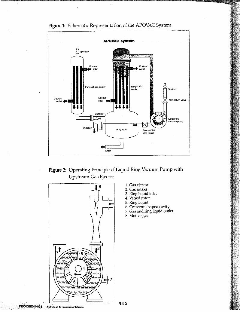
2. APOVAC System Concept
The underlying design of the APOVAC system is the combination of vacuum generation and solvent recovery through condensation in a closed circuit system composed of a liquid ring vacuum pump (LRVP) plus a subsequent cooler as shown in Figure 1 . The incoming gas stream is cooled in the LRVP and loses its solvent load during the passage through the pump and the subsequent ring- liquid cooler. Condensation occurs in the system due to
compression and Cooling in the pump - The ring liquid and condensate (solvent) are C S ~ - lected in a central Collect-ion tank which is combined with the system ring liquid cooler where the temperature rise due to the pumping and condensation process is eliminated. An optional exhaust gas cooler further
exhaust gas reduces the temperature and provides addi- tional condensation. For t h e liquid components, the ring liquid is the same as the process solvent such that the latter can then be recycled directly into the production process since it is free from any contamination.
In this basic APOVAC system, three closed circuits exist as shown in Figure 1.
- an internal ring liquid circuit between the pump and the cooler - an external process liquid (solvent) circuit between thc APOVAC system and the chemical processing unit - an external cooling medium circuit between the ApOVAC cooler and the coolant supply
The APOVAC system is self- contained, free from internal contamination, and requires, f o r its proper functioning, only energy for pumping and cooling. AS an addition to a wet process chemical production unit, it- allows the efficient recovery and recycling of solvents thus helping to reduce production Cost, consumption of energy and solvent, and environmental pollution.
534
.b.stem is the liquid ring vacuum ,@P :’ (LRVP) . A vaned impeller ,,tates eccentrically in a :Y ’ lindrical housing with : z r ~ 1 i c a 1 1 y increasing and ;,creasing gas chambers to .2nerate a suction and a com-
A pssion area in the pump. ;,tating liquid ring acts as a &ant between the impeller and .he housing. Figure 2 shows this :$sign - In this context, the :xvp is the component of choice seause of its vacuum generation :apability and its various other iunctions as outlined below: - heat exchanger function due to :ne thorough mixing effect :etween ring liquid and conveyed ,.as resulting in a strong cooling effect and a nearly isothermal ;as compression - condenser function due to com- 2ression and cooling of the gas
- reactor function between ring liquid and conveyed gas for ieutralization -tolerance to liquids and solids vhich may enter the pump - capability to work as a vacuum pump or as a compressor
3.2. Functional System Concept
These useful features of liquid ring vacuum pumps allow APOVAC systems to be designed to a small atl”er of simple but very efficient principles : * Combination of functions:
Pump: condenser; cooler; eactor; gas conveying unit for
solvent;
ank: cooling unit for liquid; condenser for
alvent; collector for ring h i d .and solvent condensate
a Separation of functional
circuits for avoid
.”
5
acuum service
contamination of process liquids and allow different temperature levels in different system stages,
- Integration in closed circuits: Several closed circuits maximize reusability of process liquids and minimize internal contamination and losses.
The APOVAC system and its components can easily be adapted or modified relative to size, ring liquid re- quirements, materials choice, control devices, accessories, etc. according to user requirements.
- Flexibility and adaptability:
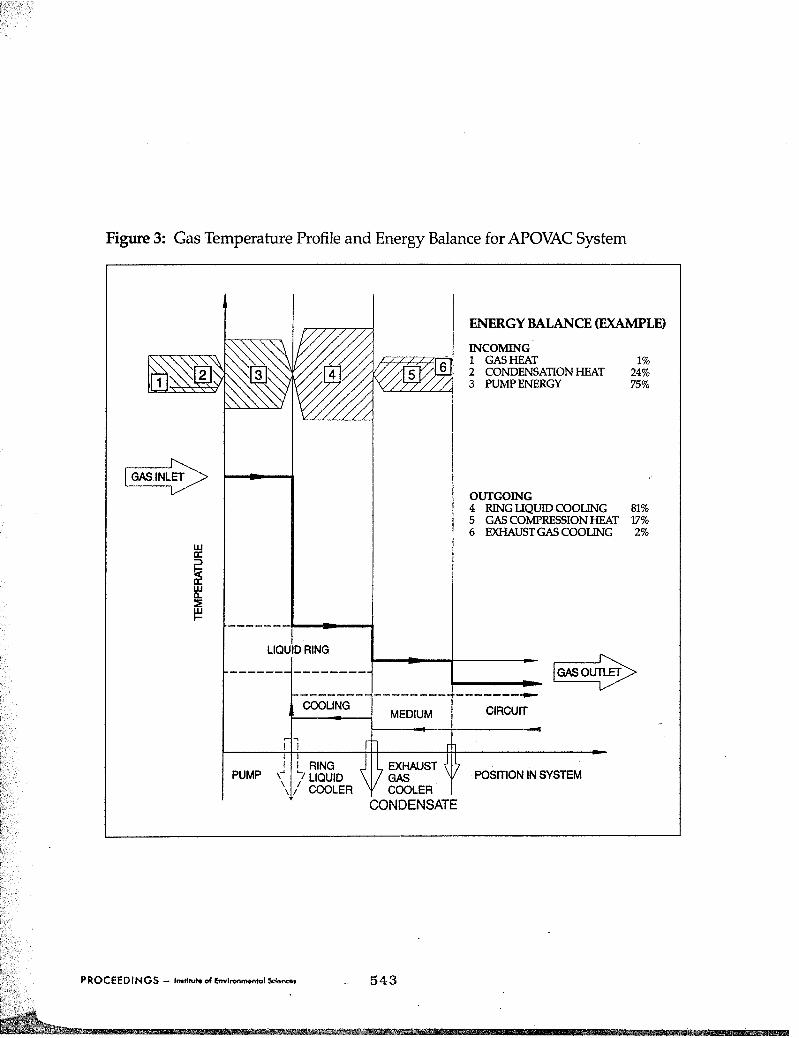
3 . 3 . Gas Temperature Profile and Energy Balance
Since condensation is generally the critical process step of any APOVAC system, its temperature profile at a given operating pressure level is of vital interest. In each APOVAC system, three different temperature levels prevail. An optional exhaust gas condenser would increase this number to four. The incoming gas stream of a temperature T, is cooled in the pump through its contact with the ring liquid and leaves the pump discharge together with part of the ring liquid at the tempera- ture T2. In the subsequent countercurrent ring li-quid cooler, the gas temperature drops down to T,. If an exhaust gas condenser exists, another cooling step down to T, takes place. The liquid ring temperature in the system oscillates between T2 and T, as a consequence of the energy- . dissipating pumping process on the one side, balanced by the cooling performance .of the liquid ring cooler on the other side. This is graphically shown in Figure 3.
535
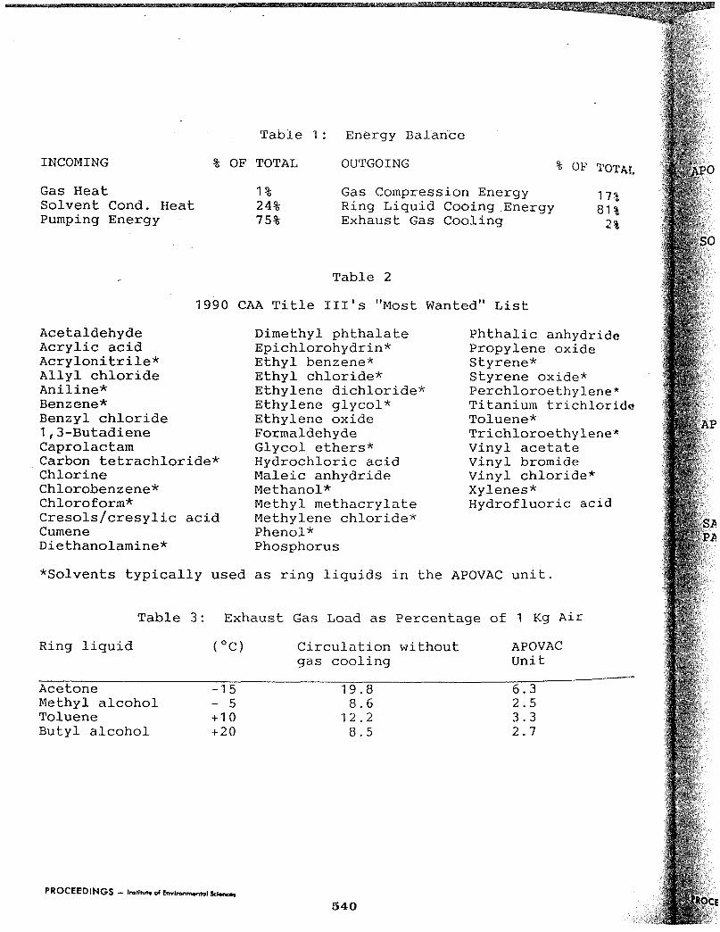
The energy balance of a typical APOV+C system . handling inert gases saturated. with solvents must consider several elements, as shown in Table 1. The relative size of each element for air at 10°C saturated with water is also given. It is important to note that the solvent recovery rate of the APOVAC system at a given pressure level depends primarily on the temperature of the exhaust gas. The APOVAC design ensures the discharge of the gas stream at the lowest possible system temperature (i.e. after the ring liquid cooler).
4 . Environmental Control: Air & Wastewater
A plant site is required to meet many environmental rules for air emissions and wastewater emissions. The new Clean Air Act (CAA) of 1990, for example, will be tougher than ever and will require a> 90% reduction in emissions by the year 2000 for 189 major chemicals. Table 2 lists the 1990 CAA "Most Wanted" list, many of which are used by the CPI. Of these compounds, over 50 percent are solvents that are typically used as ring liquids in the APOVAC system. In terms of wastewater emissions, the Clean Water Act allows a plant to discharge only the pollutants that are contained in its permit.
There are many ways to address VOCs and other forms of air pollution. Solutions include carbon adsorption systems, scrubbers, catalytic oxidation, and thermal incineration with regenerative heat recovery. For wastewater control, filtration, distillation, settling tanks, and chemical treatment are common techniques.
The above discussion focuses On pollution control as an end-of- the-pipe solution and looks at each waste stream as an individual problem. The most effective approach for environ- mental control is a "total- system'' view point. The APOVAC system solves both the air and wastewater problem as part of the process solution. Wastewater emissions are eliminated as the ring liquid is the same solvent as the process fluid.
VOC rules are met by the uniquely designed ring liquid cooler operating on the high pressure side of the LRVP. Table 3 illustrates the dramatic effect of this cooler on exhaust gas solvent load for different solvents. Finally, for difficult or high-load solvent recovery, a precondenser or exhaust gas condenser can be added. Sections 5 and 7 illustrate examples of a total process approach to solving a pollution problem, rather than a quick (and expensive) fix to a specific exhaust stream emission problem.
5. Areas of Application
t h e APOVAC systems with previously described features find a wide field of applications as described below:
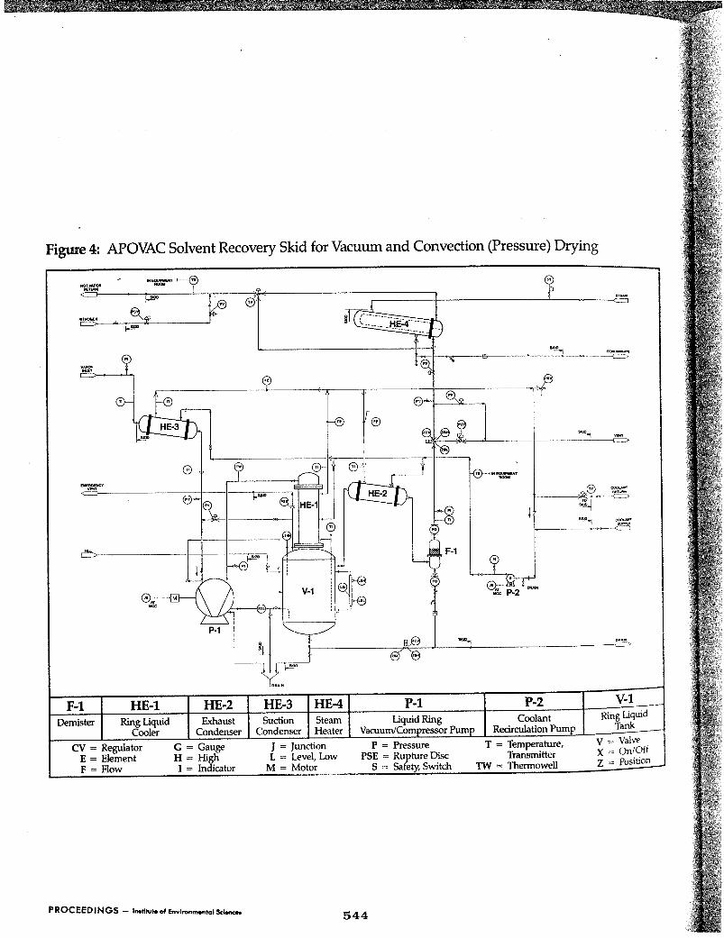
- Drying The APOVAC system operates as a vacuum pump with solvent recovery
In addition, it can be used as a compressor for filter-cake "blowing" and/or convection drying. In these applicationsf emissions can be virtuall>' eliminated by circulating an inert gas, usually N?, w i t h
intermediate condensation a t elevated pressure and lou temperature. In convection
for conventional Vacuum drying-
536 PROCEeDlNGS - -dh*mmrmdSdrar
f-
St
drying, the gas is reheated before recycling to the dryer or filter-dryer. Figure 4 shows a t y p i c a l vacuum/ convection drying installation. - Distillation Running these processes under vacuum lowers the distillation temperature and helps save costs. APOVAC units generate the re- quired vacuum and recover evaporated condensibles carried away with the air leakage.
- Crystallization crystallization in wet processes requires the removal of solvents. The crystallization process is often accelerated or better controlled under vacuum. The APOVAC units ensure the necessary vacuum plus the recovery of the process liquids. - Stripping of Solvents (Recovery of Solvents from Waste Air Streams )
In the case of adsorption, solvents are attached to a suitable medium, e.g. activated carbon. When the adsorptive capacity is reached, the solvent must be removed and ideally recovered. This is often achieved by applying heat and vacuum or pressure. APOVAC units generate vacuum and/or pressure and recover the solvents released. APOVAC compressor systems in addition allow a smaller sized system, and more efficient solvent recovery than non-pressurized systems. Finally, as pretreatment for waste air streams prior to the end-of-pipe installation, they recover between 60 to 90 percent of the solvent load, thus reducing the burden on final gas treatment unit. - Degassing of Extruder, Kneader,
Many chemical compounds contain a certain amount of volatile com- Pounds from their manufacturing
and Compounding Units
process. During thermal and mechanical processing like extrusion, kneading, and com- pounding these volatiles are released, especially at elevated temperatures, and must be re- moved. The removal process is helped significantly by the application of vacuum. APOVAC systems generate the vacuum and recover the condensible part of the volatiles. The tolerance of a liquid ring pump to small particles which are frequently released is an additional benefit. - Waste Air & Water Scrubbing for Neutralization and Purification
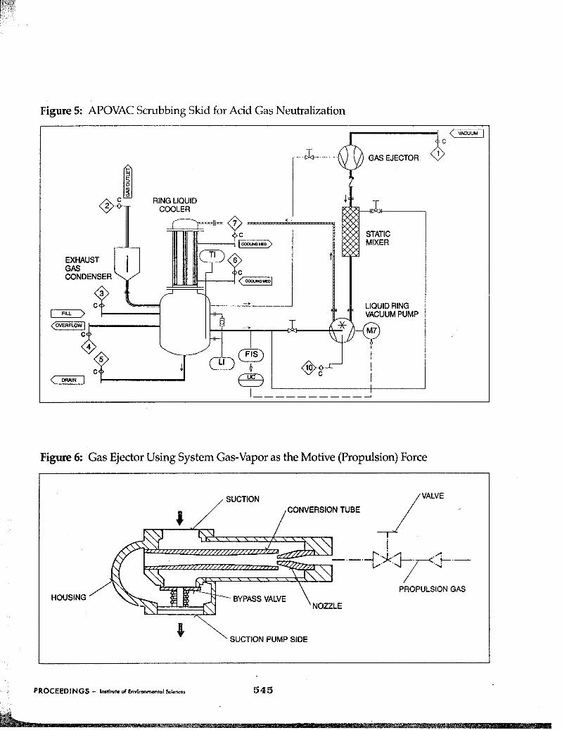
The close contact of the conveyed medium with the ring liquid allows specific reactions to take place in the pump such as neutralization of acids or de- odoration of odorous gas streams. In the former, the ring liquid is a caustic solution which, in contact with the acid gas stream, results in the removal of the acid and the formation of salts in the ring liquid. The ring liquid has to be treated regularly to remove the salt generated. A similar purifica- tion effect can be achieved with odorous gas streams through a selection of suitable ring liquids. A static-mixer, shown in Figure 5, with a side stream of the ring liquid to scrub the process gas upstream of the pump significantly helps to- increase the neutralization efficiency. - Chemical Vapor Deposition In this metal coating process, compounds of metals like aluminum, titanium and others, are deposited on the desired materials. The resulting process acid gases can be neutralized in APOVAC systems using an alkaline ring liquid. - High Vacuum Applications For applications that demand
a fully increased vacuum ,
integrated gas ejector can be incorporated. This ejector design, as shown in Figure 6 , uses the vapor in the gas/vapor space of the collector tank as the motive gas force. The result is increased vacuum without the use of fresh air or nitrogen. Organic emissions and gas con- sumption are reduced as compared to conventional air or steam jet ejector systems. - Replacement of Existing Vacuum
The APOVAC unit can replace existing steam jets where there is high water usage, environ- mental problems, or ineffi- ciencies. For conventional oil vacuum pumps, replacement with an APOVAC unit can eliminate oil contamination problems as well as the high maintenance costs associated with these systems.
Systems
The most useful way of applying the APOVAC unit is to attach one system to ,each wet process unit, such as a dryer or crystallizer. Thus, a series of APOVAC systems are installed in a chemical production plant with each system being part of a specific produc- tion unit. The exhaust gas of each unit is collected and conveyed to a central system which meets all of the specific rules for exhaust gas quality.
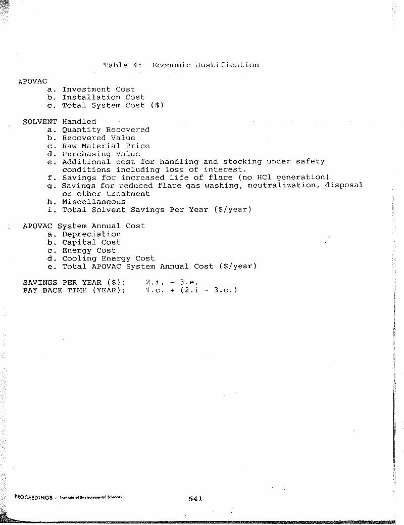
6 . Return on Investment
The incentive for an investment into an APOVAC system is in most cases the need for vacuum genera- tion combined with exhaust gas emission control and recovery of solvents. Experience has proven that the investment for an APOVAC system can often be paid back in a short time, generally less than one year, if the total costs associated with solvent utiliza- tion in the plant are considered. Table 4 illustrates a typical
ROCECDINGS - ImHm d brrfmMnmr0I Wnon
return on investment (ROI) calculation that has been taken from a fine chemical production plant.
7. Case History Installations
One of the major VOCs that must be controlled is methylene chloride ( M e C 1 2 ) . The following two case histories detail SUC- cessful APOVAC installations. One is low temperature MeC1, recovery while the other involves steam jet replacement and MeC12 recovery/ neutralization.
In this batch - granulation process, 200 Kg of MeC1, is emitted. Solvent recovery is re- quired due to environmental rules as well as for process economics. The user installed an APOVAC 2510 system with a precondenser, de- mister, exhaust condenser, and back pressure control. The ring liquid is MeC12 with a chilled brine at -4OOC as the coolant. The result is pure MeC1, recovery of greater than 96 percent, which is reused in the process.
A second installation of interest is a methylene chloride recovery/ neutralization application. In this case, the application is ;1
monomer batch reaction where 196 Kg of MeC12 is steam-stripped at a final vacuum of 5 mm Hg. The issue facing the plant was that approximately 70 percent of the MeC1, was lost to the atmosphere and the wastewater disposal system through the steam jets. A further complication was the presence of 5 percent water in the solvent, thus eliminating 1" temperature condensing as an option.
After conducting on-site test work, the user installed an APOVAC 2 5 1 0 with an exhaust condenser and gas ejector. The
538
ring liquid is a 40 percent solution of potassium carbonate (K2C03), and the coolant is at O O C . The K2C03 ring liquid provides for a phase separation as MeC1, is not soluble in K,CO,. The MeC1, is decanted from above the K2C03 in the receiver tank. Finally the K,CO, neutralizes the trace hydrochloric acid that is formed by the aqueous MeC1,. The user recovered greater than 90 percent of the MeC1, and eliminated wastewater emissions of an MeCl2/H20 mixture by replacing the steam jets.
8. Summary
This paper examined an approach to solving an emission problem that goes beyond a single-stream response. The 1990 CAA allows for site-specific issues to impact the selection of a control device. These include utility requirements, space, work force s k i l l , disposal options, and secondary environmental impacts, such as wastewater and solids generation by the proposed equipment. The APOVAC unit addresses these issues and allows the user to solve an air and wastewater * emission problem simultaneously with a single control device. This overall emission minimization approach provides benefits to several different groups associated with the plant and allows for a pro- active response to pollution control.
E1 BL IOGRAPHY 1 . M. J. Kocwin, "Liquid-Ring Pumps for Handling Gases and C'apours, ' I Sulzer Technical Review (1973) , p . 63, No. 2 . 2 . T. S o b i e s z e k , "Environmentally-compatible Evacuation of Gases and Vapours, Sulzer Technical Review ( 1986) , P. 27 ff, No. 4.
I I
3. Barry A. Perlmutter , "Combined Filter-Dryer Process Unit Improves Product Quality and Reduces Production Time , Pharmaceutical Engineering,
4. W. H. Faragallah, Liquid Rinq Vacuum Pumps and Compressors, Copyright 1985, Translated from German by David Hollywood and Anette Vogt 5. A. Kalman, J. D. Westbrook, "Recent Development in Recycle Drying for Batch Processing Industry," presented at ACHEMA, June, 1988 6. Rader, Mutsakis, Grosz-Ruell, "Better Adsorption: Try a Static Mixer, '' Chemical Engineering,
7 . P. Zahodiakin, "Puzzling Out the New Clean Air Act," Chemical Engineering, December, 1990, p.
I 1
July/AuguSt, 1989, p. 42 - 4 5 .
July, 1989, p. 137 - 142.
2 4 - 2 7 .
539
- _ Pumping Energy 75% Exhaust Gas Cooling 2
- Table 2
1990 CAA Title 111's "Most Wanted" List
Acetaldehyde Acrylic acid Acrylonitrile* Allyl. chloride Ani 1 h e *
Investment Cost Installation Cost Total System Cost ( $ )
Handled Quantity Recovered Recovered Value Raw Material Price Purchasing Value Additional cost for handling and stocking under safety conditions including loss of interest. Savings for increased life of flare (no HC1 generation) Savings for reduced flare gas washing, neutralization, disposal or other treatment Miscellaneous Total Solvent Savings Per Year ($/year)
,, APOVAC System Annual Cost a. Depreciation b. Capital Cost c. Energy Cost d. Cooling Energy Cost e. Total APOVAC System Annual Cost ($/year)
SAVINGS PER YEAR ( $ ) : 2.i. - 3.e. PAY BACK TIME (YEAR): 1.c. + (2.i - 3.e.)
Figure 2: Schematic Representation of the APOVAC System
Coolant outlet
APOVAG system
Exhaust w Suction
Non-retum valve
Liqwd-ring vacuum pump
Drain c
Figure 2: Operating Principle of Liquid Ring Vacuum Pump with Upstream Gas Ejector
1. Gas ejector 2. Gas intake 3. Ring liquid inlet 4. Vaned rotor 5. Ring liquid 6. Crescent-shaped cavity 7. Gas and ring liquid outlet 8. Motive gas
542
Figure 3: Gas Temperature Profile and Energy Balance for APOVAC System