SINCE 1974 4016 E. TENNESSEE ST. TUCSON, AZ. 85714 U.S.A. MADE IN USA 520-748-7900 FAX: 520-790-2808 E-MAIL: [email protected]http://www.otekcorp.com Catalog of 3/16/18 A CLASS 1E COMPANY NEW TECHNOLOGY M METERS ETERS™ MASTER CATALOG • CURRENT LOOP POWERED • A. C. & D.C. SIGNAL POWERED • EXTERNALLY POWERED • BAR-METERS • CONTROLLERS • TRANSMITTERS Features: *Input Fail Alarm *Isolated Serial I/O & Flash Memory *1-4 Channels *>30 Input Signals *Only <100mW/Channel *20 Housings *Mil-Spec, Industrial Grades *22 Models for F.F.&F Replacement and new DCS/SCADA applications (-N) (-9) (-L) NEW NTM™ SERIES NEED COUNTERS/TIMERS? See our UPM (Universal Panel Meter) http://www.otekcorp.com/content/universal-panel-meter The Housings, Features & Description...............Pages 1 & 2 The New Technology ...................................................Page 1 What Can You Do With It?..........................................Page 3 General Option Descriptions...................................Pages 4-6 General Specifications.................................................Page 7 Input Signal Specifications......................................Pages 7-8 Part Number Configuration Rules & Chart..................Page 9 Ordering Information..........................................Pages 10-11 Mechanical and Mounting..................................Pages 12-17 Explosion Proof Transmitter/Controller (NTM-X)...Page 18 New Technology Award.............................................Page 19 INDEX: ( )= Model Number NEED TRANSMITTERS? See the new NT Series. March 16, 2018 (0.3” Digits) (0.25” Digits) (0.6” Digits) Watch 1 minute video: http://youtu.be/WXi970VXIzM *Buy Direct From OTEK *Free N.R.E. For Customs (Rules Apply) NOW 10CFR50 APP. B & 10CFR21 & NEI 08-09 (Cyber Security) Compliant SCAN HERE FOR THE NTM CONFIGURATOR SCAN HERE FOR OTEK’S HOME PAGE CLASS 1E REPLACEMENTS
Transcript
SINCE 1974
4016 E. TENNESSEE ST.TUCSON, AZ. 85714 U.S.A.
MADEIN
USA
520-748-7900FAX: 520-790-2808E-MAIL: [email protected]://www.otekcorp.com Catalog of 3/16/18
A CLASS1E
COMPANY
NEW TECHNOLOGY MMETERSETERS™ MASTER CATALOG
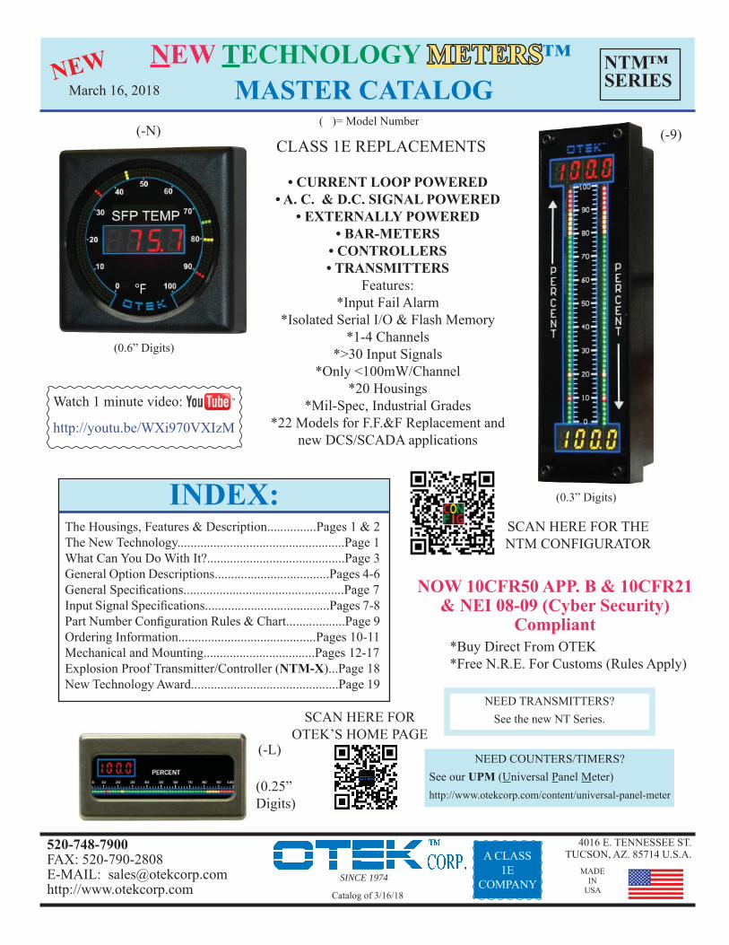
• CURRENT LOOP POWERED• A. C. & D.C. SIGNAL POWERED
• EXTERNALLY POWERED• BAR-METERS
• CONTROLLERS• TRANSMITTERS
Features:*Input Fail Alarm
*Isolated Serial I/O & Flash Memory*1-4 Channels
*>30 Input Signals*Only <100mW/Channel
*20 Housings*Mil-Spec, Industrial Grades
*22 Models for F.F.&F Replacement andnew DCS/SCADA applications
(-N) (-9)
(-L)
NEW NTM™SERIES
NEED COUNTERS/TIMERS?See our UPM (Universal Panel Meter)http://www.otekcorp.com/content/universal-panel-meter
The Housings, Features & Description...............Pages 1 & 2The New Technology...................................................Page 1What Can You Do With It?..........................................Page 3General Option Descriptions...................................Pages 4-6General Specifi cations.................................................Page 7Input Signal Specifi cations......................................Pages 7-8Part Number Confi guration Rules & Chart..................Page 9Ordering Information..........................................Pages 10-11Mechanical and Mounting..................................Pages 12-17Explosion Proof Transmitter/Controller (NTM-X)...Page 18New Technology Award.............................................Page 19
INDEX:
( )= Model Number
NEED TRANSMITTERS?See the new NT Series.
March 16, 2018
(0.3” Digits)
(0.25” Digits)
(0.6” Digits)
Watch 1 minute video:
http://youtu.be/WXi970VXIzM
*Buy Direct From OTEK*Free N.R.E. For Customs (Rules Apply)
NOW 10CFR50 APP. B & 10CFR21& NEI 08-09 (Cyber Security)
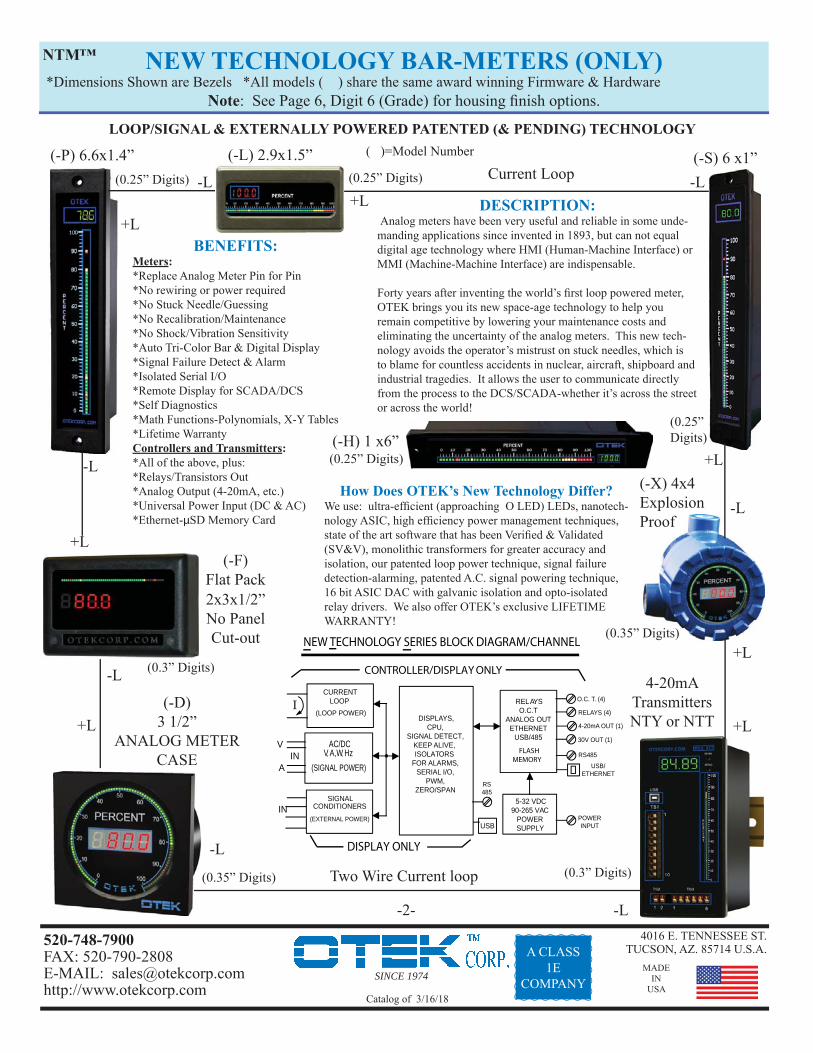
BENEFITS: Meters:*Replace Analog Meter Pin for Pin*No rewiring or power required*No Stuck Needle/Guessing*No Recalibration/Maintenance*No Shock/Vibration Sensitivity*Auto Tri-Color Bar & Digital Display*Signal Failure Detect & Alarm*Isolated Serial I/O*Remote Display for SCADA/DCS*Self Diagnostics*Math Functions-Polynomials, X-Y Tables*Lifetime WarrantyControllers and Transmitters:*All of the above, plus:*Relays/Transistors Out*Analog Output (4-20mA, etc.)*Universal Power Input (DC & AC)*Ethernet-μSD Memory Card
DESCRIPTION: Analog meters have been very useful and reliable in some unde-manding applications since invented in 1893, but can not equal digital age technology where HMI (Human-Machine Interface) or MMI (Machine-Machine Interface) are indispensable.
Forty years after inventing the world’s fi rst loop powered meter, OTEK brings you its new space-age technology to help you remain competitive by lowering your maintenance costs and eliminating the uncertainty of the analog meters. This new tech-nology avoids the operator’s mistrust on stuck needles, which is to blame for countless accidents in nuclear, aircraft, shipboard and industrial tragedies. It allows the user to communicate directly from the process to the DCS/SCADA-whether it’s across the street or across the world!
How Does OTEK’s New Technology Differ?We use: ultra-effi cient (approaching O LED) LEDs, nanotech-nology ASIC, high effi ciency power management techniques, state of the art software that has been Verifi ed & Validated (SV&V), monolithic transformers for greater accuracy and isolation, our patented loop power technique, signal failure detection-alarming, patented A.C. signal powering technique, 16 bit ASIC DAC with galvanic isolation and opto-isolated relay drivers. We also offer OTEK’s exclusive LIFETIME WARRANTY!
-2-
Two Wire Current loop
Current Loop
CURRENTLOOP
(LOOP POWER)
AC/DCV, A,
W, Hz (SIGNAL POWER)
SIGNAL
NEW TECHNOLOGY SERIES BLOCK DIAGRAM/CHANNEL
USB
RS485
RELAYSO.C.T
ANALOG OUTETHERNET
USB/485
POWERINPUT
O.C. T. (4)
RELAYS (4)
4-20mA OUT (1)
30V OUT (1)
RS485
USB/ETHERNET
DISPLAYS,CPU,
SIGNAL DETECT,KEEP ALIVE,
ISOLATORSFOR ALARMS,
SERIAL I/O,PWM,
ZERO/SPAN
•
I
V
AIN
IN CONDITIONERS
(EXTERNAL POWER)
DISPLAY ONLY
5-32 VDC90-265 VAC
POWERSUPPLY
CONTROLLER/DISPLAY ONLY
FLASHMEMORY
NTM™
( )=Model Number
-L(-H) 1 x6”
(0.25” Digits) (0.25” Digits)
(0.3” Digits)
(0.35” Digits)
(0.35” Digits)
(0.3” Digits)
(0.25” Digits)
(0.25” Digits)
SINCE 1974
4016 E. TENNESSEE ST.TUCSON, AZ. 85714 U.S.A.
MADEIN
USA
520-748-7900FAX: 520-790-2808E-MAIL: [email protected]://www.otekcorp.com Catalog of 3/16/18
A CLASS1E
COMPANY
(-0)1/8 DIN 3.8x1.9”
1 Channel
NEW TECHNOLOGY CONTROLLERS & BAR-METERS*Dimensions Shown are Bezels *All models share the same Firmware & Hardware
Note: See Page 6, Digit 6 (Grade) for housing fi nish options.
All New Technology products share the same innovative electronic circuit design. The difference between the models is their mechanical features (see Block Diagram and mechanical drawings). Some are displays only, some are single or multi channel, some can have relays, DACs, ethernet and fl ash memory, and some require an external power source. But all products contain the New Technology, which consumes less than 1% of comparable digitals (20-100mW for loop/signal powered versions) and approaches the power consumption of analog meters.
-4-
THE PRODUCTS
WHAT CAN YOU DO WITH OTEK’S NEW TECHNOLOGY?Note on Otek’s Powerless™ Technology: If your signal cannot supply mW (~ 5V/3mA), contact us or use external power models.
1. One Channel Models: -0, -4, -B, -D, -F, -H, -L, -M, -N, -P, -S, -V & -X: Implement any math function, X-Y table (25 point), polynomials (9th order), offset, tare, zero, scale, log & anti-logarithmic to affect the unit’s display at will. Some examples are: change the dis-play & data using any combi-nation as commanded by your algorithm, such as +/-/X/÷/√ or set a variable or linearize the display using X-Y tables or pol-ynomials. This works well for odd shape containers. You can also change the reading from ◦F to ◦C or ◦K or compress/expand the display (and data out) using the log and antilog functions. In addition, you can change the factory default alarm pointers and colors or delete them. Zero & Span potentiometers are in-cluded for manual adjustment. Note: Models -D and -F have internal USB serial I/O that is not accessible to the customer. Contact Otek for access.
2. Two Channel Models: -1, -2, -3 and -5 through -9 & -A: Note: Also available in models with 3 or 4 channels. Features include all those of the single channel models and each channel is 100% isolated from each other. In addition, you can add, subtract, multiply, divide, fi nd the square root between channels. You can also use one channel to monitor/control the input signal and the second channel to indicate devia-tion, differential such as PID, alarm override or one channel setpoint can be used to control another channel function. You can also use one channel as a backup if the other channel becomes disabled or use them as volume & fl ow (√) monitors/controllers. The New Tech-nology two channel models are also perfect as REM/RAD indicators/controllers (also see our RPM series with log-antilog functions for radiation monitoring).
Contact OTEK for algorithms and formulas or any idea you wish to share with our audienc-es via our Youtube or Facebook page posts.
3. Three Channel Models: -3, -5, -7, -8 and -A: Note: Also available on 4 channel models -5, -7 & -8. Otek’s New Technology three chan-nel models perform all the functions outlined in #1 and #2. Further, one channel can indicate the input variable and the other two channels can be setpoint indicators/controllers (Hi, Hi-Hi, Low and Low-Low limits), or subject the input/output to any mathematical function or algorithm such as PID or display the input vs. output and derivative, or switch scales when the input reaches a limit/band such as for fl ow-vol-ume-pressure or temperature. Monitor Volts, Amps and Watts AC or DC or any of 3 vari-ables, including Hertz, lead/lag, power factor, peak/valley or for synchronizing of power lines with the bipolar (center zero) tricolor bargraph.
The New Technology series brings Process Automation Control (PAC) within your reach and affordability. These models are compatible with any DCS/SCADA system using their USB/RS485/Ethernet I/O options and allow for ease of interface with wireless systems.
4. Four Channel Models: -5, -7 and -8: The four chan-nel models offer all of the functions outlined in #1, #2 and #3. However, with the ad-ditional channel available, the New Technology barmeters rival fl atscreens with supe-rior HMI/MMI functionality and ease of viewing/analy-sis of any combination of 4 variables. For example, Volts/Amps/Watts/Hertz or tempera-ture/pressure/pH/humidity. The four channel models can also be used to monitor/con-trol the product of the other 3 variables, making them ideal for the petrochemical industry.
Data Logging? Some models offer optional μSD memory to record 24/7 anything available via the serial I/O. Maximum capacity (and growing) is 32 GB!
OTEK’s New Technology series is only limited by your needs and imagination. Just give us a call at 520-748-7900 or email us at [email protected] and give us the challenge to develop the best algorithm for your process.
REDUNDANT CONTROL:Because all channels are 100% isolated from each other, you can use any multi-channels model as a redundant controller. If you need the “Democratic vote,” algorithm, contact OTEK or see our Model TRC (Triple Redundant Controller).
NTM™
SINCE 1974
4016 E. TENNESSEE ST.TUCSON, AZ. 85714 U.S.A.
MADEIN
USA
520-748-7900FAX: 520-790-2808E-MAIL: [email protected]://www.otekcorp.com Catalog of 3/16/18
A CLASS1E
COMPANY
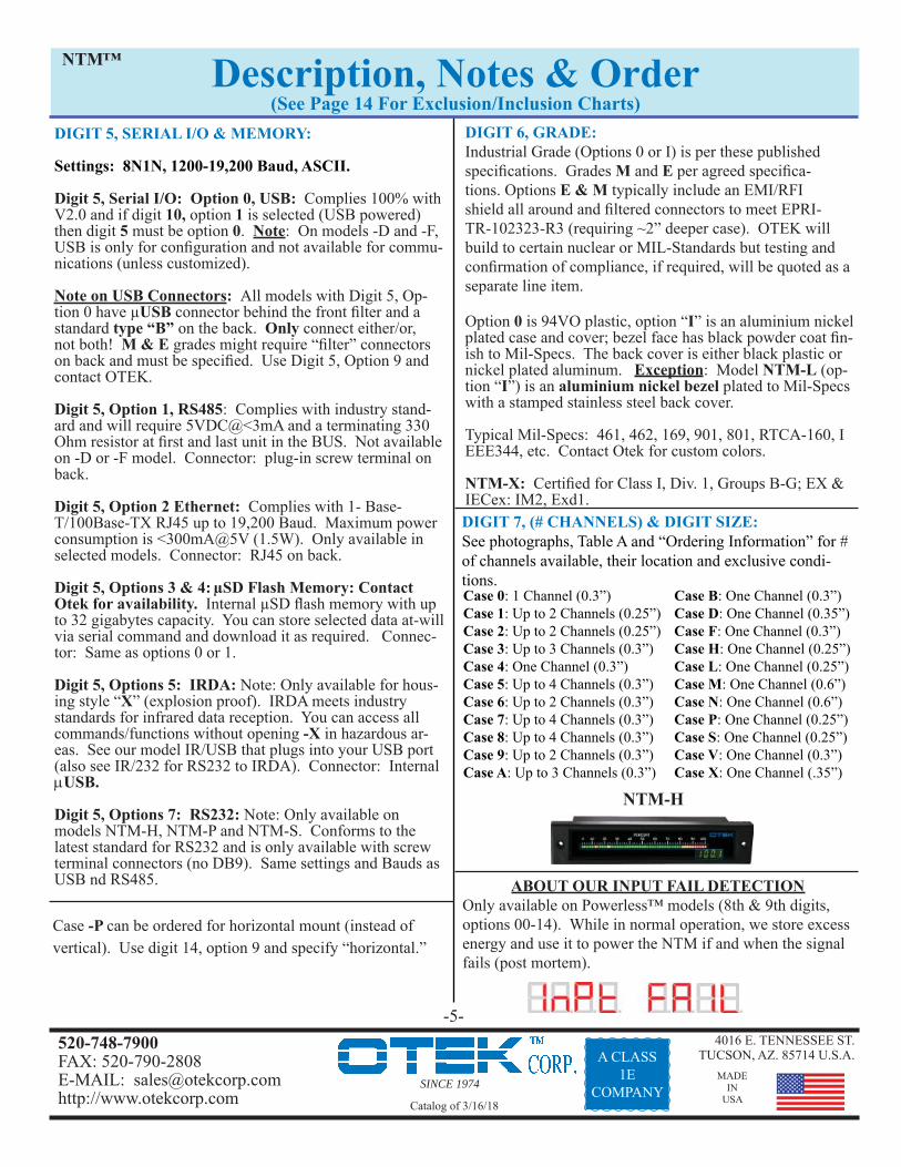
DIGIT 6, GRADE:Industrial Grade (Options 0 or I) is per these published specifi cations. Grades M and E per agreed specifi ca-tions. Options E & M typically include an EMI/RFI shield all around and fi ltered connectors to meet EPRI-TR-102323-R3 (requiring ~2” deeper case). OTEK will build to certain nuclear or MIL-Standards but testing and confi rmation of compliance, if required, will be quoted as a separate line item.
Option 0 is 94VO plastic, option “I” is an aluminium nickel plated case and cover; bezel face has black powder coat fi n-ish to Mil-Specs. The back cover is either black plastic or nickel plated aluminum. Exception: Model NTM-L (op-tion “I”) is an aluminium nickel bezel plated to Mil-Specs with a stamped stainless steel back cover.
Typical Mil-Specs: 461, 462, 169, 901, 801, RTCA-160, I EEE344, etc. Contact Otek for custom colors.
NTM-X: Certifi ed for Class I, Div. 1, Groups B-G; EX & IECex: IM2, Exd1.
-5-
DIGIT 7, (# CHANNELS) & DIGIT SIZE: See photographs, Table A and “Ordering Information” for # of channels available, their location and exclusive condi-tions.
Case B: One Channel (0.3”) Case D: One Channel (0.35”)Case F: One Channel (0.3”)Case H: One Channel (0.25”)Case L: One Channel (0.25”)Case M: One Channel (0.6”)Case N: One Channel (0.6”)Case P: One Channel (0.25”)Case S: One Channel (0.25”)Case V: One Channel (0.3”)Case X: One Channel (.35”)
Case 0: 1 Channel (0.3”)Case 1: Up to 2 Channels (0.25”)Case 2: Up to 2 Channels (0.25”)Case 3: Up to 3 Channels (0.3”)Case 4: One Channel (0.3”)Case 5: Up to 4 Channels (0.3”)Case 6: Up to 2 Channels (0.3”)Case 7: Up to 4 Channels (0.3”)Case 8: Up to 4 Channels (0.3”)Case 9: Up to 2 Channels (0.3”)Case A: Up to 3 Channels (0.3”)
Description, Notes & Order(See Page 14 For Exclusion/Inclusion Charts)
DIGIT 5, SERIAL I/O & MEMORY:
Settings: 8N1N, 1200-19,200 Baud, ASCII.
Digit 5, Serial I/O: Option 0, USB: Complies 100% with V2.0 and if digit 10, option 1 is selected (USB powered) then digit 5 must be option 0. Note: On models -D and -F, USB is only for confi guration and not available for commu-nications (unless customized).
Note on USB Connectors: All models with Digit 5, Op-tion 0 have μUSB connector behind the front fi lter and a standard type “B” on the back. Only connect either/or, not both! M & E grades might require “fi lter” connectors on back and must be specifi ed. Use Digit 5, Option 9 and contact OTEK.
Digit 5, Option 1, RS485: Complies with industry stand-ard and will require 5VDC@<3mA and a terminating 330 Ohm resistor at fi rst and last unit in the BUS. Not available on -D or -F model. Connector: plug-in screw terminal on back. Digit 5, Option 2 Ethernet: Complies with 1- Base-T/100Base-TX RJ45 up to 19,200 Baud. Maximum power consumption is <300mA@5V (1.5W). Only available in selected models. Connector: RJ45 on back.
Digit 5, Options 3 & 4: μSD Flash Memory: Contact Otek for availability. Internal μSD fl ash memory with up to 32 gigabytes capacity. You can store selected data at-will via serial command and download it as required. Connec-tor: Same as options 0 or 1.
Digit 5, Options 5: IRDA: Note: Only available for hous-ing style “X” (explosion proof). IRDA meets industry standards for infrared data reception. You can access all commands/functions without opening -X in hazardous ar-eas. See our model IR/USB that plugs into your USB port (also see IR/232 for RS232 to IRDA). Connector: InternalUSB.
Digit 5, Options 7: RS232: Note: Only available on models NTM-H, NTM-P and NTM-S. Conforms to the latest standard for RS232 and is only available with screw terminal connectors (no DB9). Same settings and Bauds as USB nd RS485.
NTM™
Case -P can be ordered for horizontal mount (instead of vertical). Use digit 14, option 9 and specify “horizontal.”
ABOUT OUR INPUT FAIL DETECTIONOnly available on Powerless™ models (8th & 9th digits, options 00-14). While in normal operation, we store excess energy and use it to power the NTM if and when the signal fails (post mortem).
Input & Display: See Below For Input Signals:*A/D: Accuracy, Linearity & Resolution: 0.5% of F.S. 1 L.S.D. over entire temperature range of 0-60 C.; 12 Bits, Conver-sion Rate: 40/sec, Averaging: 0-255, zero, span, offset, tare, math functions and 25 point X-Y tables & polynomials.*Bargraph: 51 Automatic Tricolor (R/Y/G) Segments*Digits: Four Full Digits (9.9.9.9 & -1.9.9.9).*Typical Power Consumption of Display: [email protected](>[email protected]); loop power version best at > 8mA.*Temperature Coeffi cient: +/-50PPM/°C*Operating Temperature: -10 to +60; Storage: -20 to +70°C*CCMR: >90dB@50-60Hz*Isolation: >500VDC to any other I/O & P.S.*Humidity: 5-95% RH non-condensing*Front Panel: NEMA 3. NEMA 4X on request.*Failed Signal Detect: ~ 20 seconds after > 1 minute “On” @50% of F.S. Only on loop & signal powered models.*Calibration Check: 2 years recommended.
Note 1: See page 15 for NTM replacement chart, including envi-ronmental specs vs. housing, bar length and digit size. Note 2: E and M grade electrical specifi cations are the same as Industrial unless otherwise specifi ed.
Industrial Grade Common Electrical Specifi cations
Yes! You can have the NTM powered by the input signal and have controlling outputs such as relays, O.C.T. & analog output! How it works: Your input signal (Digit 8 & 9, options 00-14 only) powers the display, CPU, serial I/O and isolators. Your external power source powers the outputs. Benefi t: You have two independent and isolated sources (fail safe). Requirement: Your signal must produce >10mW (current loop, VDC, VAC or AAC) and sustain <4V burden. If not, use exter-nal power (options 20-85 on Digits 8 & 9). AC Signal Power & Outputs? Yes, you can have both input options 01-14 (digits 8 & 9) and relays (2 maximum)without external power!Requirements: VAC input must be >90<140VAC, and AAC input must be >3<6 AAC via C.T. Ideal to monitor and control 120VAC mains! Contact OTEK for details. Zero & Span: Since the NTM requires NO recalibration, the zero & span potentiometers are internal. If required, you can change them via the serial port or remove the unit from the hous-ing and adjust.
-6-
INPUT SIGNAL SPECIFICATIONS (Digits 8 & 9)- See Pages 12 & 13Note: All ±1 LSD and % full scale range unless noted.
Option 00 & 17 For Loop Power Only:Option 00, 4-20mA Loop Powered: Burden: >3V@4mA, ≤5V@ 20mA; Range: 3-26mA; Accuracy & Linearity: ±0.5% of F.S.Option 17: 10-50mA Loop Powered: Burden: >3V@10mA, ≤5V@ 50mA; Range: 3-50mA; Accuracy & Linearity: ±0.5% of F.S.
Options 01 Through 18, A. C. Signal Powered Only:FUSE IT! Use external 1/2 ASB for Volts and 7 ASB for Amps.
Important Notes:
1) C.T. are sensitive and limited to the secondary (output) imped-ance. OTEK A.C. signal powered products present and input im-pedance of ~0.2 Ohms (~1V@5A). Make sure your C.T. can drive a >0.3 Ohm load without saturating or losing linearity. Contact Otek for assistance. Best C.T. to use: >100:5 ratio.
2) All inputs for 50-60 Hz lines. Contact Otek for 400 Hz lines.
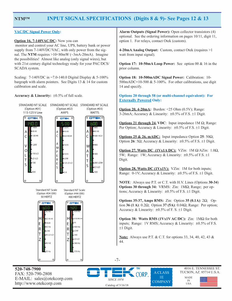
Option 01, VAC (P.T.): Burden: 0.2 Ohm & <100mW; Range: 30-140V/40-100Hz; Accuracy & Linearity: ±0.5% of F.S. Best operating range: 90-140VAC to specifications.
Option 02, 5 AMP A.C. (C.T.): Burden: <100mW; Range: .5-5A; Accuracy & Linearity: ±0.5% of F.S. Best range: 2-4 Amps.Note: Not available in “-F” case.
NTM™ The Powerful Powerless™
Options 01 Through 18, A. C. Signal Powered Only: (Continued)
Option 03, Watts A.C. (C.T. & P.T.): Not available on case -F. Range: >100<600W/50-60Hz; Accuracy & Linearity: ±0.5% of F.S. at 90-140VAC & 1-4AAC. Best operating range: 100-500 Watts. For 400 Hz lines, use option 03 and specify (03=400 Hz line) after the complete part number.
Option 04, Hertz VAC: Not available on case -F. Range: >30V<140V & >30<100Hz; Accuracy & Linearity: ±0.5% of F.S.For 400 Hz lines, use option 04 and specify (04=400 Hz line) after the complete part number.
Option 05-14: Same as options 01 through 04. PROPORTIONAL CONTROL? For proportional control, use a two (or more) channel model. Channel 1 is powered by your signal and the display signal (using a 4-20mA out) to drive the Channel 2 input. Channel 2’s 4-20mA output allows you to control your generator. The result: Channel 1 displays your AC signal and Channel 2 displays its 4-20mA output. Only Channel 2 needs power for its analog output and/or relays. Use part number NTM-(1, 2, 3, 5, 6,7, 8, 9 or A)??-269-?21-99). Note: “?”= any available option on Digits 5, 6 & 10 and specify (9=Ch 1 signal power, Ch 2 external power). Also see the new model NTI.
SINCE 1974
4016 E. TENNESSEE ST.TUCSON, AZ. 85714 U.S.A.
MADEIN
USA
520-748-7900FAX: 520-790-2808E-MAIL: [email protected]://www.otekcorp.com Catalog of 3/16/18
A CLASS1E
COMPANY
VAC/DC Signal Power Only:
Option 16, 7-140VAC/DC: Now you can monitor and control your AC line, UPS, battery bank or power supply from 7-140VDC/VAC, with only power from the sig-nal. The NTM requires >10<80mW (~3mA-20mA). Imagine the possibilities! Almost like analog (only signal wires), but with 21st century digital technology ready for your PAC/DCS/SCADA system.
Scaling: 7-140VDC in =7.0-140.0 Digital Display & 5-100% bargraph with alarm pointers. See Digits 13 & 14 for custom calibration and scale.
Accuracy & Linearity: 0.5% of full scale.
INPUT SIGNAL SPECIFICATIONS (Digits 8 & 9)- See Pages 12 & 13
-7-
Alarm Outputs (Signal Power): Open collector transistors (4) optional. See the ordering information on pages 10/11, digit 11, option 1. For relays, contact Otek (custom).
4-20mA Analog Output: Custom, contact Otek (requires >1 watt from input signal).
Option 17: 10-50mA Loop Power: See option 00 & 16 in the prior column.
Option 18: 10-500mADC Signal Power: Calibration: 10-500mADC=10-500 & 5-100%. For other calibrations, use digit 14 and specify.
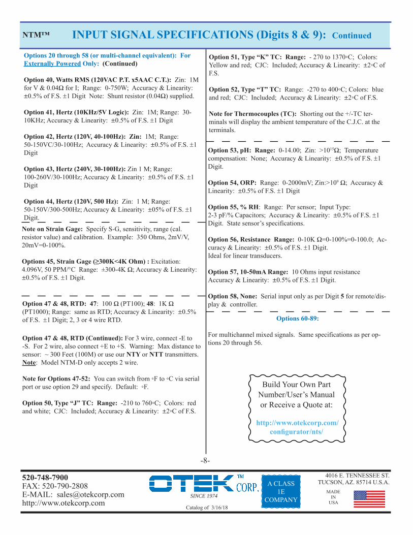
Options 20 through 58 (or multi-channel equivalent): For Externally Powered Only:
Option 28, Watts DC (1Vx1V): VZin: 1M for both inputs; Range: 0-1V; Accuracy & Linearity: ±0.5% of F.S. 1 Digit.
NOTE: Always use P.T. or C.T. with H.V. Lines (Options 30-34)Options 30 through 34: VRMS: Zin: 1MΩ; Range; per op-tions; Accuracy & Linearity: ±0.5% of F.S. 1 Digit.
Options 35-37, Amps RMS: Zin: Option 35 (0.1A): 2Ω; Op-tion 36 (1 A): 0.2Ω; Option 37 (5A): 0.04Ω; Range: Per option; Accuracy & Linearity: ±0.5% of F. S. 1 Digit.
Option 38: Watts RMS (1Vx1V AC/DC): Zin: 1MΩ for both inputs; Range: 1V RMS; Accuracy & Linearity: ±0.5% of F.S. 1 Digit.
Note: Always use P.T. & C.T. for options 33, 34, 40, 42, 43 & 44.
Option 58, None: Serial input only as per Digit 5 for remote/dis-play & controller.
NTM™
Options 60-89:
For multichannel mixed signals. Same specifications as per op-tions 20 through 56.
Option 47 & 48, RTD: 47: 100 Ω (PT100); 48: 1K Ω (PT1000); Range: same as RTD; Accuracy & Linearity: ±0.5% of F.S. 1 Digit; 2, 3 or 4 wire RTD.
Option 47 & 48, RTD (Continued): For 3 wire, connect -E to -S. For 2 wire, also connect +E to +S. Warning: Max distance to sensor: ~ 300 Feet (100M) or use our NTY or NTT transmitters. Note: Model NTM-D only accepts 2 wire.
Note for Options 47-52: You can switch from ◦F to ◦C via serial port or use option 29 and specify. Default: ◦F.
Option 50, Type “J” TC: Range: -210 to 760◦C; Colors: red and white; CJC: Included; Accuracy & Linearity: ±2◦C of F.S.
Note on Strain Gage: Specify S-G, sensitivity, range (cal. resistor value) and calibration. Example: 350 Ohms, 2mV/V, 20mV=0-100%.
Build Your Own Part Number/User’s Manual or Receive a Quote at:
http://www.otekcorp.com/confi gurator/nts/
-8-
SINCE 1974
4016 E. TENNESSEE ST.TUCSON, AZ. 85714 U.S.A.
MADEIN
USA
520-748-7900FAX: 520-790-2808E-MAIL: [email protected]://www.otekcorp.com Catalog of 3/16/18
A CLASS1E
COMPANY
Description, Notes & Order (Continued)DIGITS 8 & 9 (INPUT SIGNAL):
See Input Signal Conditioners section (Page 6 & 7) for description and specifi cations.
Digit 10 (Power Input):
Digit 10, Option 0, Powerless™, No Power Required: The Input Fail detect/Alarm (patented) fl ashes the dis-play “INPT FAIL” () and transmits this serial message for ~20 seconds, after which it will cease. This feature is available in all Powerless™ models. If desired on powered models, use option 9 on Digit 14 and specify “input fail detection.” Signal Fail Requirement: Unit must be “On” for at least 1 minute at >50% of full scale for it to operate. You can change the message via commands.
Digit 10, Option 1, USB Powered: Back up Power for signal powered models: Some applications might require “keep alive” power in case the input signal fails in Power-less™ models (signal/loop powered). If you select option 0 on Digit 10 and have a USB connection, the NTM will transmit the distress message “INPT FAIL” until the signal is restored or the USB is disconnected.
If you don’t use USB and need “keep alive” power, select options 1-4 or 9 on digit 10. The NTM “keep alive” power requirement is <3mA@5VDC.
Digit 10, Option 2, Isolated 5VDC: 5VDC is used to drive the relays (<50mA/relay) and/or the DAC via internal isolated 5-30VDC-DC (<200mA). If you order relays and analog out, you will need ~300mA/channel. This option is also isolated from the input signal.
Digit 10, Option 3, Isolated 7-32VDC: Same as option 2 but with wide input range of 7-32VDC. Effi ciency: >75%.
Digit 10, Option 4, Isolated 90-265VAC: This option ac-cepts 50-60Hz. For 100-300VDC or 400 Hz, use Digit 10, option 9 and specify. Effi ciency: >70%.
Digit 10, Option 5, Non-Isolated 5VDC: Same as option 2, but non-isolated power. Model NTM-F only.
Digit 10, Option 3, Isolated 7-32VDC: Same as option 3 but non-isolated power. Model NTM-F only.
-9-
NTM™
Flat Pack Conditions:
See page 6 for additional restrictions.
If Digit 4 = F, then Digit 10 must be Options 0, 5, 6 or 9 (NOT isolated power)
No control or analog output. Part #: NTM-F-00-1??0/2/3 or 9-00??. (??=any option).
Digit 5 (Serial) must be option 8 (None) or option 9 (custom) and is not available for external use (for factory confi guration only). Contact Otek for unsealed case. For access to the Serial I/O, contact Otek to request an unsealed case.
DIGIT 11 (CONTROL OUTPUTS & BARGRAPH COLORS):
Digit 11, Control Outputs: Options 1, 3, 5 or 7: Open Collector Transistors (O.C.T.): They are NOT isolated from each other (common emitter) but are isolated between channels and can sink a maximum of 30 mA and sustain a maximum of 30VCE. The O.C.T. are normally used to drive S.S.R. When you order relays (Digit 11, options 2, 4, 6 or 8) we use the O.C.T. to drive the relays. Power required: none.Digit 11, Options 2, 4, 6 or 8: Relays: are S.P.D.T. (1C) and can switch maximum resistive loads of 1 Amp @ 120 VAC or 30 VDC. They include 300V varistors at their con-tacts. Inductive loads must be attenuated by user. Power required: 150mW@5VDC/relay. AUTOMATIC BAR COLORS:Limits/Colors Factory default (% of Full Scale): Also see digit 14.
Low-Low Limit (<10%): Red Bar, OCT4/K4 “ON” Low Limit (<20%): Yellow Bar, OCT3/K3 “ON” High Limit (>80%): Yellow Bar, OCT2/K2 “ON”Hi-Hi Limit (>90%): Red Bar, OCT1/K1 “ON”Note: You can switch limits/relays via command.
Digit 12, Analog Output, Options 1, 3, 5 or 7: This iso-lated output is factory set to follow the input (0-F.S. in=4-20 out) but can also be set for other outputs such as external 10K Ohm potentiometer (2-22mA out) or 0-0.1VDC=.4-20mA out; or it can be serially controlled by simple com-mands via the serial port. For other outputs, use option 9 and specify, including reverse scale (4-20=20-4), bipolar and PID. Power consumption: 200mA@5VDC (1W). Ac-curacy & linearity: ±0.5% of full scale.
Analog Output External Control (Use Option 9 and specify): A) 0-100mVDC in=4-20mA out; B) 0-10K Ohm in=4-20mA out; C) Use options 58, 68, 78 or 88 and control it via serial port.
Safe Area (>20<80%): Green bar will follow signal input and if outside the limits, it will change its color to the limit’s color (yellow or red).
Bargraph or Pointer? Bargraph is by default. You can change it to pointer (one bar) via command or use option 9 on Digit 14 and specify “Pointer.” See commands in the user’s manual to customize your bargraph colors.
For other confi gurations, use option 9 on Digit 14 (fi eld confi gurable). Max power consumption per relay: 50mA@5VDC (0.25W). See Digit 14.
External Control: You can control the O.C.T./Relays via the serial port with simple commands. They don’t have to be assigned to the bar colors/set points, but are by default.Notes: 1. Digit 11 is governed by Digit 7 (# of Channels) & Digit 4 (Housing).
Description, Notes & Order (Continued)NTM™
DIGIT 12 (ANALOG /POWER OUTPUT): (Continued)
Digit 12, 30 VDC Out, Options 2, 4, 6 or 8: Use this option to power your 4-20mA transmitter or other trans-ducer. Maximum current is 25mADC. It’s isolated and is the same power source we use for options 1, 3, 5 and 7. Power consumption: 200mA@5VDC (1W)/channel.
Notes: 1. This digit 12 is governed by digits 4 (Housing) & 7 (# of Channels). Reason: Digit 12 cannot have more outputs than input channels (Digit 7), which governs.
-10-
Important Note on A.C. Powerless
The NTM, UPM & NT Series can extract energy from your A.C. signal to power itself and opto isolated serial, optional O.C.T. (Digit 11, options 1, 3, 5 or 7), and to power the optional 4-20mA output (Not 20-4mA out) from a wide input range (see specifi cations on page 6). External power is required to power the optional relays (Digit 11, options 2, 4, 6 & 8) (200mW each). If you need relays, either use the external powered options on Digits 8 & 9 (33, 37, 40 or 42) and the Digit 10 power input options (1-4) or use Power-less™ options 01-04 on Digits 8 & 9 and Power Input option 09 (custom) on Digit 10 and specify (09=Power for relays and DAC). Result: The signal will power the instru-ment and will include our patented Signal Fail Detection & Alarm. The relays and analog output are powered by the external power option (all 100% isolated).
For User-Software or drivers,visit:
otekcorp.com/content/support-downloads
SINCE 1974
4016 E. TENNESSEE ST.TUCSON, AZ. 85714 U.S.A.
MADEIN
USA
520-748-7900FAX: 520-790-2808E-MAIL: [email protected]://www.otekcorp.com Catalog of 3/16/18
A CLASS1E
COMPANY
Description, Notes & Order (Continued)
DIGIT 13 (SCALE PLATE):
Digit 13, Scale Plate: Option 0 is a standard scale plate that reads 0-100%. Use option 9 for custom printing and contact Otek. You must send us your custom scale plate drawings when ordering and we will send you our custom scale drawing for your approval.
DIGIT 14 (RANGE/CALIBRATION):
0=Factory Default: 0-Full Scale Input=0-100% bar and 0-100.0 digits. Colors: <10>90%: Red; <20>80%: Yellow; >20<80%: Green. Use Option 9 (custom) and contact Otek. Also see Control Outputs (Digit 11). Bargraph Default: 0-Full scale=0-100%. You can program it for single pointer, or three or fi ve bars via the serial port.
OTHER IMPORTANT DATA:
Math Functions: +, -, x, ÷, √, Polynomials to 9th order, 25 Point X-Y table, zero, offset, span and tare. You can add, subtract, multiply, divide (etc.) one channel to/from another channel and display the result in the other channel (i.e. V (Ch.1)xA(Ch.2)=W(Ch.3).
Signal Failure Alarm: Requires approximately 1 minute of normal (mid-scale) operation for it to alarm the display and output the serial data after the signal (Powerless ™) has ceased (post- mortem).
Serial I/O: Setting: 8N1N, 1200-19,200 BAUD, 8 Charac-ter Address
PID: Programmable (best with >dual channel models) automatic or manual with external 10K Ohm potentiom-eter (option 56). See models NTY & NTT for dedicated 4-20mA transmitters (same technology).
High Quality: No matter their size or number of chan-nels all use the same (SV & V) fi rmware, hardware and commands. No matter their grade (Industrial, Mil-Spec, Nuclear) they all carry a lifetime warranty.
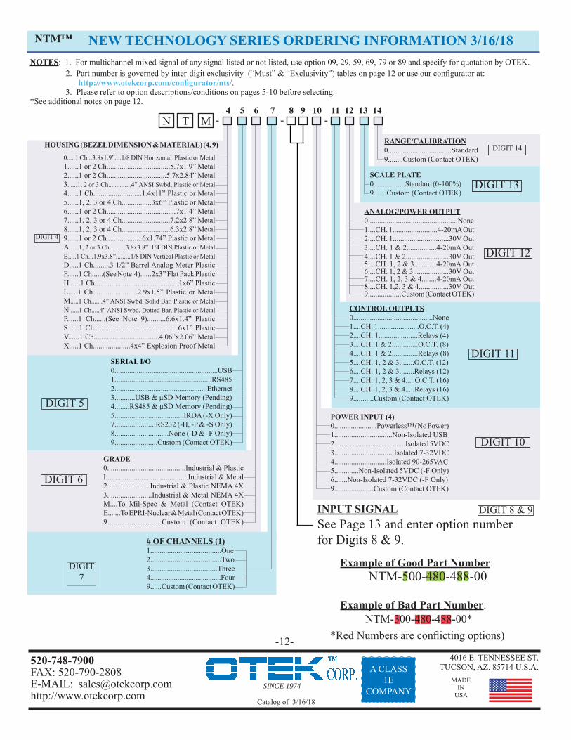
0.....1 Ch...3.8x1.9”....1/8 DIN Horizontal Plastic or Metal1......1 or 2 Ch..................................5.7x1.9” Metal2......1 or 2 Ch................................5.7x2.84” Metal3......1, 2 or 3 Ch..............4” ANSI Swbd, Plastic or Metal4......1 Ch..........................1.4x11” Plastic or Metal 5......1, 2, 3 or 4 Ch................3x6” Plastic or Metal6......1 or 2 Ch.....................................7x1.4” Metal 7......1, 2, 3 or 4 Ch..........................7.2x2.8” Metal 8......1, 2, 3 or 4 Ch..........................6.3x2.8” Metal 9......1 or 2 Ch...................6x1.74” Plastic or MetalA......1, 2 or 3 Ch..........3.8x3.8” 1/4 DIN Plastic or MetalB.....1 Ch...1.9x3.8”.........1/8 DIN Vertical Plastic or MetalD.....1 Ch.........3 1/2” Barrel Analog Meter PlasticF......1 Ch......(See Note 4)......2x3” Flat Pack PlasticH......1 Ch.............................................1x6” Plastic L.....1 Ch........................2.9x1.5” Plastic or MetalM.....1 Ch.......4” ANSI Swbd, Solid Bar, Plastic or Metal N......1 Ch.....4” ANSI Swbd, Dotted Bar, Plastic or MetalP......1 Ch......(See Note 9)..........6.6x1.4” Plastic S......1 Ch.............................................6x1” Plastic V......1 Ch...................................4.06”x2.06” MetalX.....1 Ch....................4x4” Explosion Proof Metal
POWER INPUT (4) 0.......................Powerless™ (No Power)1...............................Non-Isolated USB2.......................................Isolated 5VDC3................................Isolated 7-32VDC4............................Isolated 90-265VAC5.............Non-Isolated 5VDC (-F Only)6.......Non-Isolated 7-32VDC (-F Only)9.....................Custom (Contact OTEK)
GRADE0..........................................Industrial & PlasticI............................................Industrial & Metal2.......................Industrial & Plastic NEMA 4X3........................Industrial & Metal NEMA 4XM....To Mil-Spec & Metal (Contact OTEK)E.......To EPRI-Nuclear & Metal (Contact OTEK)9...........................Custom (Contact OTEK)
NOTES: 1. For multichannel mixed signal of any signal listed or not listed, use option 09, 29, 59, 69, 79 or 89 and specify for quotation by OTEK. 2. Part number is governed by inter-digit exclusivity (“Must” & “Exclusivity”) tables on page 12 or use our confi gurator at: http://www.otekcorp.com/confi gurator/nts/. 3. Please refer to option descriptions/conditions on pages 5-10 before selecting.*See additional notes on page 12.
N T M
NTM™
Example of Good Part Number: NTM-500-480-488-00
Example of Bad Part Number: NTM-300-480-488-00*
*Red Numbers are confl icting options)
4 5 6 7 8 9 10 11 12 13 14
SINCE 1974
4016 E. TENNESSEE ST.TUCSON, AZ. 85714 U.S.A.
MADEIN
USA
520-748-7900FAX: 520-790-2808E-MAIL: [email protected]://www.otekcorp.com Catalog of 3/16/18
A CLASS1E
COMPANY
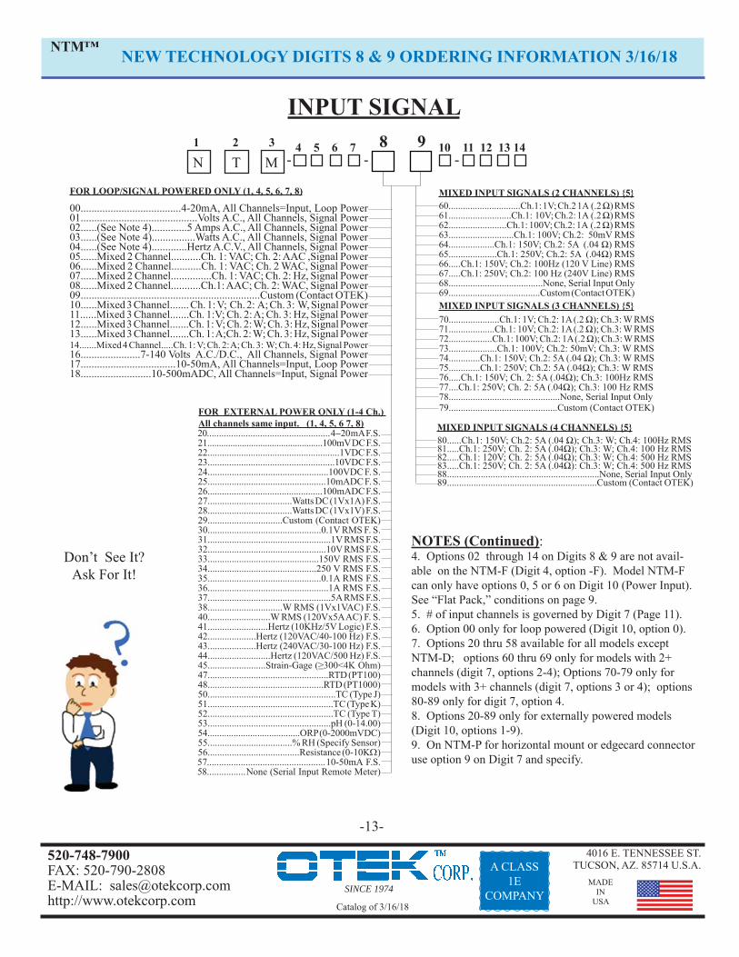
70.....................Ch.1: 1V; Ch.2: 1A (.2 Ω); Ch.3: W RMS71...................Ch.1: 10V; Ch.2: 1A (.2 Ω); Ch.3: W RMS72..................Ch.1: 100V; Ch.2: 1A (.2 Ω); Ch.3: W RMS73....................Ch.1: 100V; Ch.2: 50mV; Ch.3: W RMS74.............Ch.1: 150V; Ch.2: 5A (.04 Ω); Ch.3: W RMS75.............Ch.1: 250V; Ch.2: 5A (.04Ω); Ch.3: W RMS76.....Ch.1: 150V; Ch. 2: 5A (.04Ω); Ch.3: 100Hz RMS77....Ch.1: 250V; Ch. 2: 5A (.04Ω); Ch.3: 100 Hz RMS78..............................................None, Serial Input Only79.............................................Custom (Contact OTEK)
-13-
NEW TECHNOLOGY DIGITS 8 & 9 ORDERING INFORMATION 3/16/18
1 2 3 -
INPUT SIGNAL
MIXED INPUT SIGNALS (2 CHANNELS) {5}
-
MIXED INPUT SIGNALS (4 CHANNELS) {5}
FOR LOOP/SIGNAL POWERED ONLY (1, 4, 5, 6, 7, 8)
00.....................................4-20mA, All Channels=Input, Loop Power01...........................................Volts A.C., All Channels, Signal Power02......(See Note 4).............5 Amps A.C., All Channels, Signal Power03......(See Note 4)................Watts A.C., All Channels, Signal Power04......(See Note 4).............Hertz A.C.V., All Channels, Signal Power05......Mixed 2 Channel...........Ch. 1: VAC; Ch. 2: AAC ,Signal Power06......Mixed 2 Channel...........Ch. 1: VAC; Ch. 2 WAC, Signal Power07......Mixed 2 Channel...............Ch. 1: VAC; Ch. 2: Hz, Signal Power08......Mixed 2 Channel...........Ch.1: AAC; Ch. 2: WAC, Signal Power09..................................................................Custom (Contact OTEK)10......Mixed 3 Channel....... Ch. 1: V; Ch. 2: A; Ch. 3: W, Signal Power11......Mixed 3 Channel.......Ch. 1:V; Ch. 2: A; Ch. 3: Hz, Signal Power 12......Mixed 3 Channel.......Ch. 1: V; Ch. 2: W; Ch. 3: Hz, Signal Power 13......Mixed 3 Channel.......Ch. 1: A;Ch. 2: W; Ch. 3: Hz, Signal Power14.......Mixed 4 Channel.....Ch. 1: V; Ch. 2: A; Ch. 3: W; Ch. 4: Hz, Signal Power 16......................7-140 Volts A.C./D.C., All Channels, Signal Power17...................................10-50mA, All Channels=Input, Loop Power18..........................10-500mADC, All Channels=Input, Signal Power
MIXED INPUT SIGNALS (3 CHANNELS) {5}
FOR EXTERNAL POWER ONLY (1-4 Ch.) All channels same input. (1, 4, 5, 6 7, 8)mA F.S.21..................................................100mV DC F.S.22.......................................................1VDC F.S.23.....................................................10VDC F.S.24..................................................100VDC F. S.25.................................................10mADC F. S.26................................................100mADC F.S.27...................................Watts DC (1Vx1A) F.S.28...................................Watts DC (1Vx1V) F.S.29...............................Custom (Contact OTEK)30...............................................0.1V RMS F. S.31...................................................1V RMS F.S.32.................................................10V RMS F.S.33..............................................150V RMS F.S.34.............................................250 V RMS F.S. 35...............................................0.1A RMS F.S.36..................................................1A RMS F.S.37...................................................5A RMS F.S.38...............................W RMS (1Vx1VAC) F.S.40..........................W RMS (120Vx5A AC) F. S.41.........................Hertz (10KHz/5V Logic) F.S.42....................Hertz (120VAC/40-100 Hz) F.S.43....................Hertz (240VAC/30-100 Hz) F.S.44..........................Hertz (120VAC/500 Hz) F.S.45........................Strain-Gage (≥300<4K Ohm)47..................................................RTD (PT100)48................................................RTD (PT1000)50.....................................................TC (Type J)51....................................................TC (Type K)52....................................................TC (Type T)53...................................................pH (0-14.00)54.......................................ORP (0-2000mVDC)55...................................% RH (Specify Sensor)56......................................Resistance (0-10K10-50mA F.S.None (Serial Input Remote Meter)
10 11 12 13 14
NOTES (Continued): 4. Options 02 through 14 on Digits 8 & 9 are not avail-able on the NTM-F (Digit 4, option -F). Model NTM-F can only have options 0, 5 or 6 on Digit 10 (Power Input). See “Flat Pack,” conditions on page 9. 5. # of input channels is governed by Digit 7 (Page 11).6. Option 00 only for loop powered (Digit 10, option 0).7. Options 20 thru 58 available for all models except NTM-D; options 60 thru 69 only for models with 2+ channels (digit 7, options 2-4); Options 70-79 only for models with 3+ channels (digit 7, options 3 or 4); options 80-89 only for digit 7, option 4.8. Options 20-89 only for externally powered models (Digit 10, options 1-9).9. On NTM-P for horizontal mount or edgecard connector use option 9 on Digit 7 and specify.
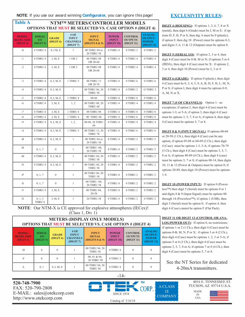
METERS (DISPLAY ONLY MODELS)OPTIONS THAT MUST BE SELECTED VS. CASE OPTION # (DIGIT 4)
MODEL/BEZEL SIZE
(DIGIT 4)
SERIAL I/O
(DIGIT 5)
GRADE (DIGIT 6)
# OF INPUT
CHANNELS (DIGIT 7)
INPUT SIGNAL
(DIGITS 8 & 9)
POWERINPUT
(DIGIT 10)
CONTROL OUTPUTS (DIGIT 11)
ANALOG OUTPUT/POWER
(DIGIT 12)
-D 0 0 1 00 THRU 04, 20 THRU 58 0 THRU 4 0 0
-F 0 0 1 00, 01 & 04, 20 THRU 58 0 THRU 3 0 0
-L 0, 1 0, I, M, E 1 00 THRU 04, 20 THRU 58 0 THRU 4 0 0
EXCLUSIVITY RULES:
DIGIT 4 (HOUSING): If options 1, 2, 6, 7, 8 or X (metal), then digit 6 (Grade) must be I, M or E; if op-tions D, F, H, P or S, then dig. 6 must be 0 (plastic); if option F, then dig 10 (Power) must be options 0-3, and digits 5, 6, 11 & 12 (Outputs) must be option 0.
DIGIT 5 (SERIAL I/O): If option 2, 3 or 4, then digit 4 (Case) must be 0-B, M or N; if options 5 or 6 (IRDA), then digit 4 (Case) must be X; if options 2, 3 or 4, then digit 10 (Power) must be 2, 3 or 4.
DIGIT 6 (GRADE): If option 0 (plastic), then digit 4 (Case) must be 0, 3, 4, 5, 9, A, B, D, F, H, L, M, N, P or S; if option I, then digit 4 must be options 0-9, A, M, N or X.
DIGIT 7 (# OF CHANNELS): Option 1: no exceptions; if option 2, then digit 4 (Case) must be options 1-3, or 5-A; if option 3, then digit 4 (Case) must be options 3, 5, 7, 8 or A; if option 4, then digit 4 (Case) must be options 5, 7 or 8.
DIGIT 8 & 9 (INPUT SIGNAL): If options 00-04 or 20-58 (1 Ch.), then digit 4 (Case) can be any option; if option 05-08 or 60-69 (2 Ch.), then digit 4 (Case) must be options 1-3, 5-A; if options 70-79 (3 Ch.), then digit 4 (Case) must be options 3, 5, 7, 8 or A; if options 80-89 (4 Ch.), then digit 4 (case) must be options 5, 7 or 8; if options 00-14, then digits 10, 11 & 12 (Power & Outputs) must be option 0; if options 20-89, then digit 10 (Power) must be options 1-4.
DIGIT 10 (POWER INPUT): If option 0 (Power-less™) then digit 5 (Serial) must be options 0 or 1 and digits 8 & 9 (Input Signal) must be options 00 through 14 (Powerless™); if option 1 (USB), then digit 5 (Serial) must be option 0; if option 4, then digit 4 (Case) cannot be option F (Flat Pack).
DIGIT 11 OR DIGIT 12 (CONTROL OR ANA-LOG/POWER OUT): If option 0, no restrictions; if options 1 or 2 (1 Ch.), then digit 4 (Case) must be options 0-B, M, N, P or X; if option 3 or 4 (2 Ch.), then digit 4 (Case) must be options 1, 2, 3 or 5-A; if options 5 or 6 (3 Ch.), then digit 4 (Case) must be options 3, 5, 7, 8 or A; if options 7 or 8 (4 Ch.), then digit 4 (Case) must be options 5, 7 or 8.
Table A
NOTE: Our NTM-X is CE approved for explosive atmospheres (IECex)!(Class 1, Div 1)
See the NT Series for dedicated 4-20mA transmitters.
NOTE: If you use our award winning Confi gurator, you can ignore this page!
SINCE 1974
4016 E. TENNESSEE ST.TUCSON, AZ. 85714 U.S.A.
MADEIN
USA
520-748-7900FAX: 520-790-2808E-MAIL: [email protected]://www.otekcorp.com Catalog of 3/16/18
Option 9: (6x1.74”), Plastic or Metal 4”/.3” GE180, Yokogawa 180, Dixson, WeschlerOption A: (3.8x3.8”), 1/4 DIN Plastic or Metal 2.5”/.4” Any 1/4 DIN (96x96mm) Meter
Option B: (3.8x1.9”), 1/8 DIN Plastic or Metal, Vertical 2.5”/.4” Any 1/8 DIN (48x96mm) Meter, VerticalOption D: (3 1/2”), Barrel Analog Meter Plastic 3”/.4” Any Analog Meter Case 3 1/2” Barrel
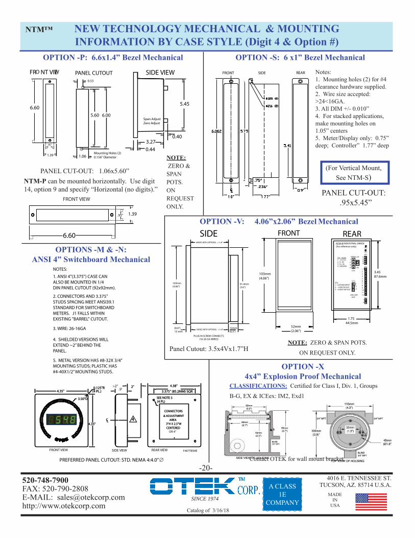
Option F: (2x3”), Flat Pack Plastic 3”/.3” Any Otek “Flat Pack” 516 through 528, 400-414 & FPMOption H: (1x6”), Plastic 2.5”/.25” Otek’s HIQSLIM 1, 2 or 3Option L: (2.9x1.5”), Plastic or Metal 2.5”/.25” Otek’s LPM, LPE, NPM, VelonexOption M: (ANSI Switchboard .4”), Plastic or Metal 6.5”/.6” DB40, Weschler, Dixson, Otek’s HIQTBS & HIQ123Option N: (ANSI Switchboard .4”), Plastic or Metal 6.5”/.6” DB40, Weschler, Dixson, Otek’s HIQ124 & HIQTBEOption P: (6.6x1.4”), Plastic 4”/.25” Dixson BE 051/101, Sigma, VMI, Otek’s HIQ101Option S: (6x1”), Plastic 2.5”/.25” Otek’s HIQSLIM 1, 2 or 3
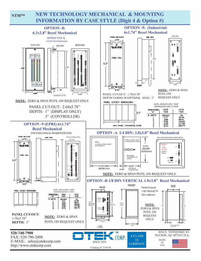
Panel Cutout: 5.42x2.70”Depth: 1” (Display Only 3” (Controller)
NEW TECHNOLOGY MECHANICAL & MOUNTINGINFORMATION BY CASE STYLE (Digit 4 & Option #)
NTM™
(3.78”)96mm
4.30”
TO MOUNTING BRACKETS
(1.9”)48mm
1.78
3.55
45.2mm
90.2mm
1 2 3 4
1 2 3
ST1 ST3ST2
ST5
SPAN ZERO1 2 3 4 5 6 7 8 9 10 1112 1 2
DAC/30V OUTSERIAL I/O
ST4
USB
1 2 3 4
. 2
2.2056mm
5mm 12mm.5
PLUG IN SCREW CONNECTORS
(16-26 GA WIRES)
OPTION V4.06x2.06”
Bezel Mechanical
PLUG IN SCREW CONNECTS(16-26 GA WIRES)
(0.6”)15 mm
12mm(0.5”)
103mm(4.06”)
91.4mm(3.6”)
SIDE
VARIES WITH OPTIONS: >1<8”
VARIES WITH OPTIONS: >1<8”
52mm(2.06”)
03mm4.06”)
FRONT
1.7544.5mm
3.4587.6mm
REAR
ST5:1: CUSTOM INPUT2: -LOOP/0V OUT3: +LOOP/30V OUT
SERIAL I/O
ST5123
ST1
ST3
ST2
SPAN
ZERO
123456789101112
1234
12
DAC/30V
OUT
ST4
USB
1234
ST4: RS4851: +5 V D.C.2: D- (B)3: D+ (A)4: GROUND
NTM-B INDUSTRIAL GRADE
(For reference only)
Panel Cutout: >3.5”<4.0” H x >1.8”<2” W
REAR VIEWFRONT VIEW
2.84"
5.70
”
5.40
”
1.70"
CHANNEL A
*CHANNEL B
SPAN
ZERO
ST2A 1 2 3 4 5 6 7 8 9101112
1234
ST3A
ST4A 12
ST1A 1234
1234
SPAN
ZERO
ST2B
121110 9 8 7 6 5 4 3 2 1
ST3B4321
ST1B4321SERIAL I/O
1234
ST5A
5.70
0
SIDE VIEW
5.40
0
FRONT VIEW REAR VIEW
1.90" 1.65"
SEE USER’ MANUAL FOR ACTUAL CONNECTIONS PER MODEL CONFIGURATION.
CHANNEL A
*CHANNEL B
SPAN
ZERO
ST2A 1 2 3 4 5 6 7 8 9101112
1234
ST3A
ST4A 12
ST1A 1234
1234
SPAN
ZERO
ST2B
121110 9 8 7 6 5 4 3 2 1
ST3B4321
ST1B4321SERIAL I/O
1234
ST5A
.5”1 .0”2 .0”
INDUSTRIAL PANEL CUT-OUT: 1.67x5.42”NOTE: INDUSTRIAL HAS EURO PLUG CONNECTORS
(MIL OR EPRI HAS FILTERED TERMINAL CONNECTORS)DEPTH VARIES WITH OPTION. MAX: 3”
NOTE: CH. B HAS PINOUT NUMBERED FROM BOTTOM TO TOP.
“XXD”“XXC”
Notes: 1. Ch. B has pinout numbered from bottom to top.2. Industrial grade has euro-plus con-nectors; MIL & EPRI have fi ltered terminal connectors.3. Depth varies with option. Max: 3”
FRONT VIEW SIDE VIEW F#87TBSME
CL
PREFERRED PANEL CUTOUT: STD. NEMA 4:4.0”
4.35"
4.35"
0.125"R 2"
3.50"D
4.38"
3.375" (85.2MM) SQR.
(4 PL)
(4 PL.)
CONNECTORS
& ADJUSTMENTAREA
3"H X 2.5"WCENTERED
4
.9’
SEE NOTE 5
REAR VIEW
CL
4.35"
4.35"
0.125"R 2"
3.50"D
4.38"
3.375" (85.2MM) SQR.
(4 PL)
(4 PL.)
CONNECTORS
& ADJUSTMENTAREA
3"H X 2.5"WCENTERED OR 4”
4
>2”
SEE NOTE 5
1. ANSI 4"(3.375") CASE CAN ALSO BE MOUNTED IN 1/4 DIN PANEL CUTOUT (92x92mm).2. CONNECTORS AND 3.375" STUDS SPACING MEET ANSI39.1 STANDARD FOR SWITCHBOARD METERS. J1 FALLS WITHIN EXISTING "BARREL" CUTOUT.3. WIRE: 26-16GA4. SHIELDED VERSIONS WILL EXTEND ~2” BEHIND THE PANEL.
5. METAL VERSION HAS #8-32X 3/4” MOUNTING STUDS; PLASTIC HAS#4-40X1/2” MOUNTING STUDS.
NOTE: ZERO & SPAN POTS. ON REQUEST ONLY.
NOTE: ZERO & SPAN POTS. ON REQUEST ONLY.
NOTE: ZERO & SPAN
POTS. ON REQUEST
ONLY.
NOTE: ZERO & SPAN POTS. ON REQUEST ONLY.
SINCE 1974
4016 E. TENNESSEE ST.TUCSON, AZ. 85714 U.S.A.
MADEIN
USA
520-748-7900FAX: 520-790-2808E-MAIL: [email protected]://www.otekcorp.com Catalog of 3/16/18
NEW TECHNOLOGY MECHANICAL & MOUNTINGINFORMATION BY CASE STYLE (Digit 4 & Option #)
NOTE: DISPLAYS ARE 1” DEEPCONTROLLERS ARE 2.3” DEEP
NTM™
OPTION -B 1/8 DIN VERTICAL 1.9x3.8” Bezel Mechanical
.75”
1”
5.50”
NOTE: DISPLAYS ARE 1” DEEPCONTROLLERS ARE 2.3” DEEP
PLUG IN SCREW CONNECTS(16-26 GA WIRES)
2.2056mm
.25mm
.512mm
96mm(3.78”)
90.2mm(3.55”)
SIDE
48mm(1.9”)
96mm(3.78”)
FRONT
REAR VIEW
1.65”
CH B
CH ASPANZERO
SPANZERO
1234
ST1B
ST1A
1234
12
ST3
ST5
1234
1.7845.2mm
3.5590.2mm
REAR
4.3” TOMOUNTINGBRACKETS
RS485 (ST4):4. GROUND3: D+ (A)2: D- (B)1: +5 V D.C.
ST5:1: CUSTOM INPUT2: -LOOP/0V OUT3: +LOOP/30V OUT
SERIAL I/O
ST5123
ST1
ST3
ST2
SPAN
ZERO
123456789101112
1234
12
DAC/30V
OUT
ST4
USB
1234
NTM-A REAR VIEW (SIGNAL POWER MODEL)
SERIAL I/OCH A
SPAN
1234
ST1A
ZERO
WARNING! H.V. IN THIS SECTION.
ST41 2 3 4
CH B
SPAN
1234
ST1B
ZERO
CH C
SPAN
1234ST1C
ZERO
USB
DO NOT TOUCH
Panel Cutout: 1.85” Wx3.62”H(92 x 46mm)
3”.75”
NTM-9 MECHANICAL INFORMATION (EPRI)
REAR VIEW
TYPICAL CONNECTIONS
5.5”
SPAN
ZERO
1 2 3 4 5 6 7 8 9101112
1234
12
1234
1234
SPAN
ZERO
121110 9 8 7 6 5 4 3 2 1
4321
4321SERIAL I/O
1234
ST4
ST5A
ST2A
ST3
ST1A
ST1B
ST2B
ST5B
NOTE: ZERO & SPAN POTS. ON REQUEST ONLY.
NOTE: ZERO & SPAN POTS. ON REQUEST ONLY.
NOTE: ZERO & SPAN POTS. ON REQUEST ONLY.
NOTE: ZERO & SPAN POTS. ON REQUEST ONLY.
NOTE: ZERO & SPAN
POTS. ON REQUEST
ONLY.
2.60”
5.65”
SIDE VIEW REAR VIEWFRONT VIEW
CH 2
CH 1 CH 3
CH 4
OPTION NTM -8: 6.3x2.8” Bezel Mechanical
SPAN
ZERO
1 2 3 4 5 6 7 8 9101112
1234
12
CHA
NN
EL C
*CH
AN
NEL
D
1234
1234
SPAN
ZERO
121110 9 8 7 6 5 4 3 2 1
4321
4321
SERIAL I/O
SPAN
ZERO
1 2 3 4 5 6 7 8 9101112
1234
12
1234
1234
1234
SPAN
ZERO
121110 9 8 7 6 5 4 3 2 1
4321
4321
CHA
NN
EL A
*CH
AN
NEL
B
(Updated 2/22/18)
SINCE 1974
4016 E. TENNESSEE ST.TUCSON, AZ. 85714 U.S.A.
MADEIN
USA
520-748-7900FAX: 520-790-2808E-MAIL: [email protected]://www.otekcorp.com Catalog of 3/16/18
A CLASS1E
COMPANY
OPTION -FFlat Pack 2x3” Mechanical
No Panel Cut Out Required!
OPTION -D3 1/2” Analog Meter Case Mechanical
OPTION -L: 2.9x1.5” Bezel Mechanical
Mounting Instructions:1. Drill a 3/8 - 1/2" diameter hole.2. Attach supplied double sided tape to back of it.3. Pass wires through hole.4. Align and Press NTM-F on panel (that is all!)5. Don’t pull on wires (26 gage)!
NO PANEL CUT-OUT!
-19-
HOLE DIAMETER: 2.75”MTG. HOLES (4): 0.15” Ø
3.26
0.550.35
1.84
4-M3
0.40
FRONT VIEW SIDE VIEW
3.26
OTEK
Ø2.71CL
DISPLAYAREA2.5” Ø
NEW TECHNOLOGY MECHANICAL & MOUNTINGINFORMATION BY CASE STYLE (Digit 4 & Option #)
NEW TECHNOLOGY MECHANICAL & MOUNTINGINFORMATION BY CASE STYLE (Digit 4 & Option #)
NTM™
PANEL CUT-OUT: .95x5.45”
FRONT SIDE REAR
NTM-P can be mounted horizontally. Use digit 14, option 9 and specify “Horizontal (no digits).”
6.60
.95” 1.39
FRONT VIEW
CLASSIFICATIONS: Certifi ed for Class I, Div. 1, Groups
B-G, EX & ICEex: IM2, Exd1
OPTIONS -M & -N: ANSI 4” Switchboard Mechanical
Notes:1. Mounting holes (2) for #4 clearance hardware supplied.2. Wire size accepted: >24<16GA.3. All DIM +/- 0.010”4. For stacked applications, make mounting holes on 1.05” centers5. Meter/Display only: 0.75” deep; Controller” 1.77” deep
(For Vertical Mount, See NTM-S)
OPTION -V: 4.06”x2.06” Bezel MechanicalREAR
1.7544.5mm
3.4587.6mm
ST5:1: CUSTOM INPUT2: -LOOP/0V OUT3: +LOOP/30V OUT
SERIAL I/O
ST5123
ST1
ST3
ST2
SPAN
ZERO
123456789101112
1234
12
DAC/30V OUT
ST4
USB
1234
ST4: RS4851: +5 V D.C.2: D- (B)3: D+ (A)4: GROUND
NTM-B INDUSTRIAL GRADE (For reference only)
FRONT
52mm(2.06”)
103mm(4.06”)
SIDE
PLUG IN SCREW CONNECTS(16-26 GA WIRES)
(0.6”)15 mm
12mm(0.5”)
103mm(4.06”)
91.4mm(3.6”)
VARIES WITH OPTIONS: >1<8”
VARIES WITH OPTIONS: >1<8”
6.60
FRO NT VIEW
.95”
1.39
5.60
1.06
6.00
0.53
Mounting Holes (2)0.156” Diameter
PANEL CUTOUT
5.45
0.40
SIDE VIEW
3.270.44
Span AdjustZero Adjust
Panel Cutout: 3.5x4Vx1.7”H
NOTES:
1. ANSI 4"(3.375") CASE CAN ALSO BE MOUNTED IN 1/4
DIN PANEL CUTOUT (92x92mm).
2. CONNECTORS AND 3.375"
STUDS SPACING MEET ANSI39.1 STANDARD FOR SWITCHBOARD METERS. J1 FALLS WITHIN
EXISTING "BARREL" CUTOUT.
3. WIRE: 26-16GA
4. SHIELDED VERSIONS WILL EXTEND ~2” BEHIND THE
PANEL.
5. METAL VERSION HAS #8-32X 3/4”MOUNTING STUDS; PLASTIC HAS#4-40X1/2” MOUNTING STUDS.
FRONT VIEW SIDE VIEW F#87TBSME
CL
PREFERRED PANEL CUTOUT: STD. NEMA 4:4.0”
4.35"
4.35"
0.125"R 2"
3.50"D
4.38"
3.375" (85.2MM) SQR.
(4 PL)
(4 PL.)
CONNECTORS
& ADJUSTMENTAREA
3"H X 2.5"WCENTERED
4
.9’
SEE NOTE 5
REAR VIEW
CL
4.35"
4.35"
0.125"R 2"
3.50"D
4.38"
3.375" (85.2MM) SQR.
(4 PL)
(4 PL.)
CONNECTORS
& ADJUSTMENTAREA
3"H X 2.5"WCENTERED OR 4”
4
>2”
SEE NOTE 5
NOTE: ZERO & SPAN POTS. ON REQUEST ONLY.
NOTE: ZERO & SPAN POTS.
ON REQUEST ONLY.
SINCE 1974
4016 E. TENNESSEE ST.TUCSON, AZ. 85714 U.S.A.
MADEIN
USA
520-748-7900FAX: 520-790-2808E-MAIL: [email protected]://www.otekcorp.com Catalog of 3/16/18
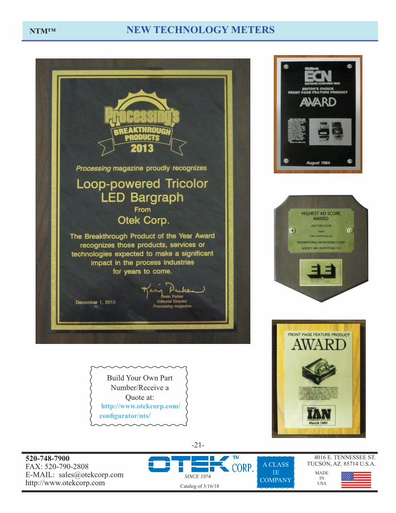
ABOUT THE NEW TECHNOLOGY METER (NTM) SERIES:In 1974 Otek introduced the 1st loop powered LCD DPM. In 1985, the 1st LED loop powered DPM. In 1998, the 1st auto tricolor bargraph LCD loop powered bar-meter. In 2005, the 1st LED loop powered bar-meter. Now we bring you the culmination of 40 years dedicated to the POWER of the LOOP!
We are proud to introduce our new NTM Series of instruments! All models use the same patent pending technology along with our patented hardware and fi rmware to give you the highest reli-ability (lifetime warranty) at the lowest cost.
The NTM Series includes various features such as: automatic (programmable) tricolor bar-graph, automatic signal fail detect (open or short), indication and serial transmission with run time stamp and unit’s ID, isolated retransmission (4-20mA), and universal power input (5-32VDC and 90-265VAC). The NTM Series offers several math functions such as X-Y tables, polynomials and log-anti-log functions.
The NTM signal and external power series also feature isolated serial USB, RS485 or Ethernet μSD memory card to 32GB, open collector transistors (4/channel) and SPDT relays (4/channel). You can tell us your custom needs and we’ll make it (or might already have it)! The new Otek NT product line offers a series of 4-20 mA transmitters suitable for most control applications. The NT Series is designed to replace the old thumbwheel-style controllers with a new device which combines transmitter and controller functions in a single, compact unit. Like the NTM series, NT transmitter/controllers offer: 4 digit, low-power, hi-intensity LED’s, 4 digits per display, over 30 input signal conditioners standard, tricolor bar graph with program-mable set points, and options for signal or external power. Control functions include: serial I/O, isolated analog retransmission, OCT or relay control outputs.
INSTANT PRICING: Our state-of-the-art Confi gurator allows you to build your specifi c part number, receive a price and create a customized user’s manual. If you already have a complete part number, you can simply enter it to get instant pricing or create the custom user’s manual. There is no waiting, no hassle and no RFQ.
NTM™
ABOUT OTEK:
OTEK Corporation was founded in 1974 by Dr. Otto Fest, whose enduring goal has been to provide the very best in process measurement and control instrumentation, coupled with unparalleled service. Otek designs, develops and manufactures their products right here in the U.S., deploying state-of-the-art technology and using only the highest quality materials and components. Key products include digital panel meters, bargraphs, controllers, batch counters, and process data loggers. The high quality of our products allows us to offer an unprecedented lifetime warranty.
OTEK also offers a 15 day evaluation program at no charge.