NEW TRENDS FOR SEISMIC ENGINEERING OF STEEL AND COMPOSITE STRUCTURES Jerome F. Hajjar 1 and Mark D. Denavit 2 1 Professor and Chair, Department of Civil and Environmental Engineering, Northeastern University, Boston, MA 02115. 2 Graduate Research Assistant, Department of Civil and Environmental Engineering, University of Illinois at Urbana-Champaign, Urbana, IL 61801. ABSTRACT This paper summarizes ongoing research and trends in practice for both practical and innovative steel and composite steel-concrete structural systems. Selected recent work in the United States will be reviewed and trends in the design specifications will be identified, including new tests and analyses on composite steel/concrete systems aimed at improving the current U.S. design provisions; and recent research on self-centering steel frame systems with replaceable energy-dissipating fuses that provide new strategies for ensuring sustainable structures after major hazardous events. KEYWORDS Articulated Fuse Systems, Composite, Design, Seismic, Self-Centering Systems, Steel INTRODUCTION The structural engineering profession has a history of constant innovation as engineers and researchers strive to increase the safety, economy, and performance of our built environment. One manifestation of this innovation is the path new structural systems take from novel concept to introduction and eventually full integration in codes and specifications. Steel-concrete composite structural systems have recently received expanded attention in specifications within the United States. Composite members have been included in the American Institute of Steel Construction (AISC) steel specification since the 1936 Specification for the Design, Fabrication and Erection of Structural Steel for Buildings (AISC 1936). However, the provisions only addressed composite beams until the 1986 Specification for Structural Steel Buildings – Load and Resistance Factor Design (AISC 1986), when provisions for composite columns and beam-columns were added based upon research consolidated through the Structural Stability Research Council and related venues in the 1960’s through the early 1980’s. The provisions for composite systems underwent only
Transcript
NEW TRENDS FOR SEISMIC ENGINEERING OF STEEL AND COMPOSITE STRUCTURES
Jerome F. Hajjar1 and Mark D. Denavit2
1 Professor and Chair, Department of Civil and Environmental Engineering,
Northeastern University, Boston, MA 02115. 2 Graduate Research Assistant, Department of Civil and Environmental Engineering,
University of Illinois at Urbana-Champaign, Urbana, IL 61801.
ABSTRACT This paper summarizes ongoing research and trends in practice for both practical and innovative steel and composite steel-concrete structural systems. Selected recent work in the United States will be reviewed and trends in the design specifications will be identified, including new tests and analyses on composite steel/concrete systems aimed at improving the current U.S. design provisions; and recent research on self-centering steel frame systems with replaceable energy-dissipating fuses that provide new strategies for ensuring sustainable structures after major hazardous events. KEYWORDS Articulated Fuse Systems, Composite, Design, Seismic, Self-Centering Systems, Steel INTRODUCTION The structural engineering profession has a history of constant innovation as engineers and researchers strive to increase the safety, economy, and performance of our built environment. One manifestation of this innovation is the path new structural systems take from novel concept to introduction and eventually full integration in codes and specifications. Steel-concrete composite structural systems have recently received expanded attention in specifications within the United States. Composite members have been included in the American Institute of Steel Construction (AISC) steel specification since the 1936 Specification for the Design, Fabrication and Erection of Structural Steel for Buildings (AISC 1936). However, the provisions only addressed composite beams until the 1986 Specification for Structural Steel Buildings – Load and Resistance Factor Design (AISC 1986), when provisions for composite columns and beam-columns were added based upon research consolidated through the Structural Stability Research Council and related venues in the 1960’s through the early 1980’s. The provisions for composite systems underwent only
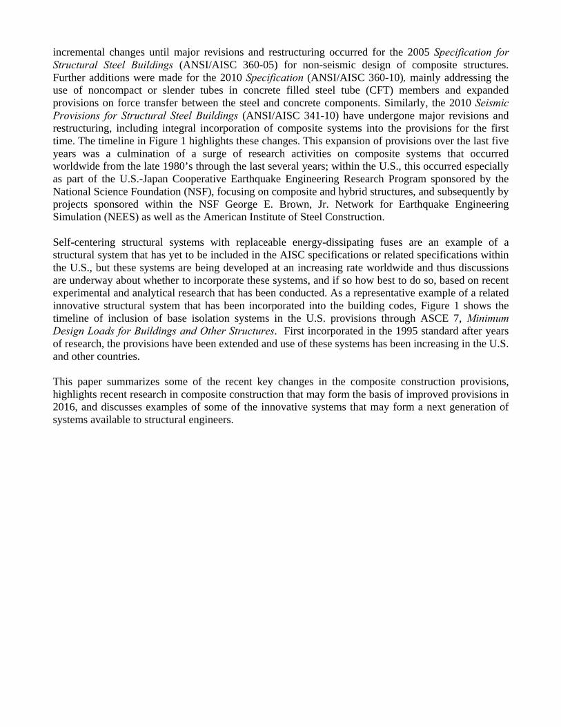
incremental changes until major revisions and restructuring occurred for the 2005 Specification for Structural Steel Buildings (ANSI/AISC 360-05) for non-seismic design of composite structures. Further additions were made for the 2010 Specification (ANSI/AISC 360-10), mainly addressing the use of noncompact or slender tubes in concrete filled steel tube (CFT) members and expanded provisions on force transfer between the steel and concrete components. Similarly, the 2010 Seismic Provisions for Structural Steel Buildings (ANSI/AISC 341-10) have undergone major revisions and restructuring, including integral incorporation of composite systems into the provisions for the first time. The timeline in Figure 1 highlights these changes. This expansion of provisions over the last five years was a culmination of a surge of research activities on composite systems that occurred worldwide from the late 1980’s through the last several years; within the U.S., this occurred especially as part of the U.S.-Japan Cooperative Earthquake Engineering Research Program sponsored by the National Science Foundation (NSF), focusing on composite and hybrid structures, and subsequently by projects sponsored within the NSF George E. Brown, Jr. Network for Earthquake Engineering Simulation (NEES) as well as the American Institute of Steel Construction. Self-centering structural systems with replaceable energy-dissipating fuses are an example of a structural system that has yet to be included in the AISC specifications or related specifications within the U.S., but these systems are being developed at an increasing rate worldwide and thus discussions are underway about whether to incorporate these systems, and if so how best to do so, based on recent experimental and analytical research that has been conducted. As a representative example of a related innovative structural system that has been incorporated into the building codes, Figure 1 shows the timeline of inclusion of base isolation systems in the U.S. provisions through ASCE 7, Minimum Design Loads for Buildings and Other Structures. First incorporated in the 1995 standard after years of research, the provisions have been extended and use of these systems has been increasing in the U.S. and other countries. This paper summarizes some of the recent key changes in the composite construction provisions, highlights recent research in composite construction that may form the basis of improved provisions in 2016, and discusses examples of some of the innovative systems that may form a next generation of systems available to structural engineers.
Figure 1: Timeline of Integration of Composite Columns and Base Isolation into Specifications RECENT CHANGES IN THE STEEL-CONCRETE COMPOSITE PROVISIONS Significant variations in behavior and progress of damage in composite members are possible due to the range of relative proportions of steel and concrete permissible in these members. Some composite beam-columns are concrete dominant and will behave more like reinforced concrete members while others are steel dominant and will behave more like structural steel members (Hajjar and Gourley 1996). Design provisions for composite members must account for this variation while simultaneously minimizing conflicts with structural steel and reinforced concrete provisions and recognizing the advantages of composite design. Numerous changes have been made to the U.S. design provisions over that past decade in light of these goals. Key changes are highlighted below. Composite Member Strength Limit States Prior to the 2005 Specification for Structural Steel Buildings (AISC 2005), the axial and flexural strengths of composite beam-columns were based on calculations that determined an equivalent steel section. This approach had limitations in that it was not applicable to columns with steel ratios below 4% and it often underestimated the contribution of the concrete, particularly for concrete-dominant composite beam-columns with low steel ratios (Griffis 2005). The beam-column strength interaction provisions in AISC (2005) are based more directly on mechanics principles. The cross section strength may now be determined using one of two methods: the plastic stress distribution method, which is applicable to most common composite column cross sections; and the more general strain-compatibility method, which is comparable to approaches often taken to compute reinforced concrete section strength. The compressive strength for axially loaded columns including length effects is then computed using a column curve that is algebraically identical to that for steel columns, and an effective stiffness, EIeff, that is based on a curve fit to experimental data (Leon et al. 2007). As a result of the new methodology, the range of applicability of the provisions was extended to members with steel ratios as low as 1%.
2010
Year20152000 2005 2010
Introductionof seismicisolation
20021993 1995
Major revisions and1999 2005
2002
1998 2005
1985 1990 1995
1988
Introduction of
1992
Seismic Isolation in ASCE/SEI 7 Minimum Design Loads of Buildings and Other Structures
Steel-Concrete Composite in ANSI/AISC 341 Seismic Provisions for Structural Steel Buildings
Steel-Concrete Composite in ANSI/AISC 360 Specification for Structural Steel Buildings
1986 1993
1997 2005
2010
2010MajorIntroduction of
compositeconstruction and integration
restructuring
composite restructuringSlender CFTsLoad Transfer
beam-columns
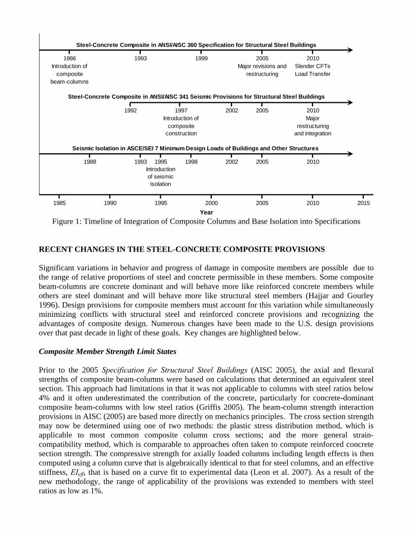
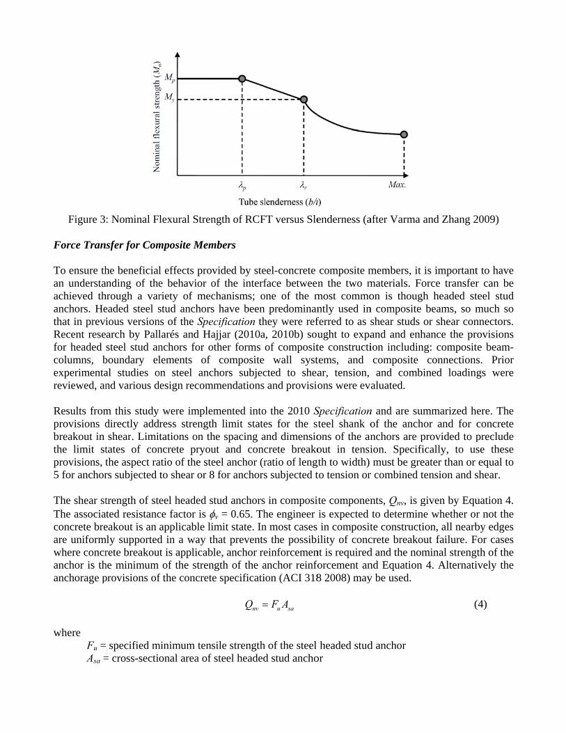
The 2010 Specification provides clarified requirements for assessing compact composite members subjected to combined flexure and axial force. A number of design methods satisfy these requirements and the commentary to the specification identifies three in particular. The first method involves utilizing the interaction equations derived for structural steel members. This method is simple although conservative, as it typically underpredicts the contribution of the concrete. This is the method required for CFT members with noncompact or slender tubes, as discussed in the next section. The second method utilizes the plastic stress distribution method. The nominal strength interaction surface of the section is determined using the plastic stress distribution at several points along the interaction curve, and length effects are accounted for using a reduction factor on axial strength at all points on the interaction surface that is calculated based on the case of pure compression (Leon and Hajjar 2008). The third method is an approach presented in AISC Design Guide 6 (Griffis 1992), not presented here for brevity. Slenderness Limits for CFT Members The concrete core of concrete filled steel tube (CFT) members prevents inward buckling of the steel tube, delaying local buckling as compared to hollow tubes members. This was not recognized in the 1999 Specification, where tube slenderness limits were identical for both hollow and filled steel tubes. Provisions in the 2005 Specification adjusted the slenderness limits but only allowed for compact CFT members. Based on the work of Varma and Zhang (2009), new slenderness provisions are included in the 2010 Specification, allowing for the use of noncompact and slender tubes in CFT members. Elastic local buckling behavior of filled tubes (accounting for the difference in the shape of the local buckling mode between hollow and filled tubes) informs both the noncompact/slender limit and the critical stress in the slender range. While compact steel tubes are assumed to provide enough confinement to the concrete core so that it develops a compressive stress of 0.85f′c for rectangular CFTs or 0.95f′c for circular CFTs (where f′c is the specified compressive strength of the concrete), noncompact and slender steel tubes are assumed to be unable to provide adequate confinement after the concrete core reaches a compressive stress 0.70f′c. These assumptions lead to stress distributions through the section from which axial and flexural strength may be computed. As a representative example, the flexural strength provisions for RCFT members will be presented in detail. The member is classified as either compact, noncompact, or slender based on slenderness ratios (TABLE 1). For a member to be classified as compact, all of the components (i.e., both the web and flange) need to be compact, and similarly for being classified as noncompact. Once the member is classified, the nominal flexural capacity, Mn, is computed as described below and using the stress distributions shown in Figure 2. The provisions result in a typical relationship between strength and slenderness as shown in Figure 3. The resistance factor is φb = 0.90.
TABLE 1 LIMITING WIDTH-TO-THICKNESS RATIOS OF RCFT MEMBERS SUBJECTED TO FLEXURE
Description of Element
Width-to- thickness
ratio
λp Compact/
Noncompact
λr Noncompact/
Slender
Maximum Permitted
Flange of HSS b/t 2.26 yE F 3.00 yE F 5.00 yE F
Web of HSS h/t 3.00 yE F 5.70 yE F 5.70 yE F
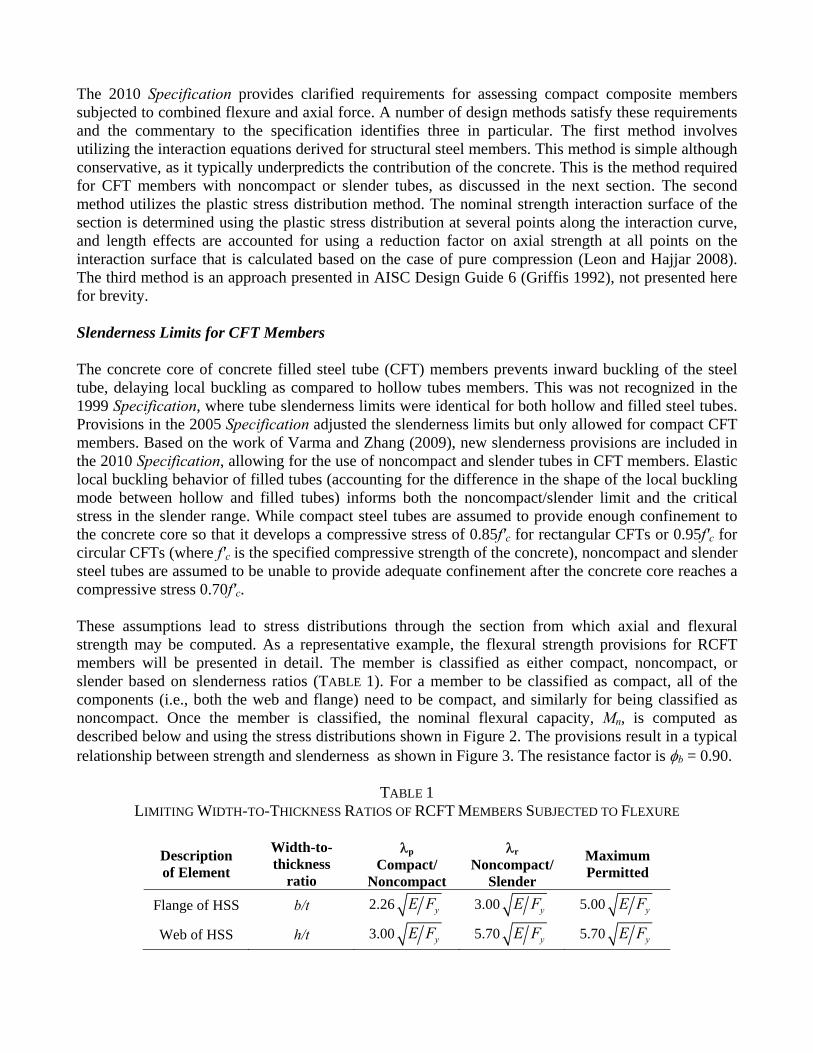
For compact sections: n pM M= (1)
where Mp = moment corresponding to the plastic stress distribution (Figure 2).
For noncompact sections:
( ) pn p p y
r p
M M M Mλ λλ λ
⎛ ⎞−= − − ⎜ ⎟⎜ ⎟−⎝ ⎠
(2)
where
λ, λp, and λr = slenderness ratios determined from TABLE 1. In the case of both the web and flange are noncompact, the slenderness values are those which produce the lowest strength.
My = yield moment corresponding to yielding of the tension flange and first yield of the compression flange. It is calculated assuming a linear elastic stress distribution with the maximum concrete compressive stress limited to 0.7f′c and the maximum steel stress limited to Fy (Figure 2).
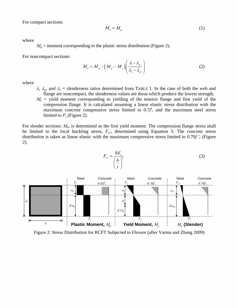
For slender sections: Mn, is determined as the first yield moment. The compression flange stress shall be limited to the local buckling stress, Fcr, determined using Equation 3. The concrete stress distribution is taken as linear elastic with the maximum compressive stress limited to 0.70f ′c (Figure 2).
2
9 scr
EFbt
=⎛ ⎞⎜ ⎟⎝ ⎠
(3)
Figure 2: Stress Distribution for RCFT Subjected to Flexure (after Varma and Zhang 2009)
Steel Concrete
Plastic Moment, Mp Yield Moment, My Mn (Slender)
Steel Concrete Steel Concrete
d
b
Fy Fy Fcr
Fy Fy Fy
ap
d-ap
ay
ay
d-2ay
acr
d-acr
0.85f′c 0.70f′c 0.70f′c
Figure 3 Force Tran To ensure than understaachieved thanchors. Hethat in previRecent resefor headed columns, bexperimentareviewed, an Results fromprovisions dbreakout in the limit stprovisions, t5 for anchor The shear stThe associaconcrete breare uniformwhere concranchor is thanchorage p
where Fu = Asa =
: Nominal F
sfer for Com
he beneficialanding of thehrough a vareaded steel sious versionarch by Pallsteel stud an
boundary elal studies ond various d
m this studydirectly addshear. Limi
tates of conthe aspect rars subjected
trength of stated resistanceakout is an
mly supportedrete breakou
he minimum provisions of
= specified m= cross-secti
lexural Stren
mposite Mem
l effects proe behavior oriety of mecstud anchors
ns of the Spelarés and Hanchors for olements of
on steel ancdesign recom
were impledress strengthtations on thncrete pryouatio of the steto shear or 8
eel headed sce factor is φapplicable lid in a way t
ut is applicabof the stren
f the concret
minimum tenonal area of
ngth of RCF
mbers
vided by steof the interfchanisms; os have beenecification thajjar (2010aother forms
composite chors subjec
mmendations
emented intoh limit statehe spacing aut and conceel anchor (r8 for anchors
stud anchorsφv = 0.65. Thimit state. Inthat preventsble, anchor rength of the ate specificati
nvQ =
sile strengthf steel headed
FT versus Sle
eel-concrete face betweenone of the m predominan
hey were refa, 2010b) souof composit
wall systcted to sheaand provisio
o the 2010 Ses for the sand dimensiocrete breakoratio of lengs subjected t
s in composihe engineer n most cases s the possibieinforcemenanchor reinfoion (ACI 318
u saF A=
h of the steel d stud ancho
enderness (a
composite mn the two m
most commontly used inferred to as sught to expate constructitems, and ar, tension, ons were ev
Specificationteel shank oons of the anout in tensi
gth to width) to tension or
ite componenis expected in compositility of conc
nt is requiredforcement an8 2008) may
headed studor
after Varma a
members, it materials. Foon is though
n composite shear studs and and enhion includincomposite and combi
aluated.
n and are sumof the anchnchors are pion. Specifimust be gre
r combined t
nts, Qnv, is gto determinte constructicrete breakoud and the nomnd Equation y be used.
d anchor
and Zhang 2
is importantorce transferh headed stbeams, so mor shear con
hance the prng: composit
connectionsined loading
mmarized hor and for c
provided to pically, to useater than or tension and s
given by Eque whether orion, all nearbut failure. Fminal streng4. Alternati
(
2009)
t to have r can be teel stud much so nnectors. rovisions te beam-s. Prior gs were
ere. The concrete preclude se these equal to
shear.
uation 4. r not the by edges
For cases gth of the ively the
(4)
The tensile strength of steel headed stud anchors in composite components, Qnt, is given by Equation 5. The associated resistance factor is φv = 0.75. For cases where an anchor is located within 1.5 times its height to a free edge or 3 times its height to another anchor, anchor reinforcement is required and the nominal strength of the anchor is the minimum of the strength of the anchor reinforcement and Equation 5. Alternatively the anchorage provisions of the concrete specification (ACI 318 2008) may be used.
nt u saQ F A= (5) The interaction strength of steel headed stud anchors in composite components is assessed with Equation 6. Again, where concrete breakout in shear is applicable or edge conditions or group effects exist, anchor reinforcement should be provided or ACI 318 (2008) should be used.
5 3 5 3
1.0rt rv
t nt v nv
Q QQ Qφ φ
⎡ ⎤⎛ ⎞ ⎛ ⎞⎢ ⎥+ ≤⎜ ⎟ ⎜ ⎟⎢ ⎥⎝ ⎠ ⎝ ⎠⎣ ⎦
(6)
where Qrt = required tensile strength
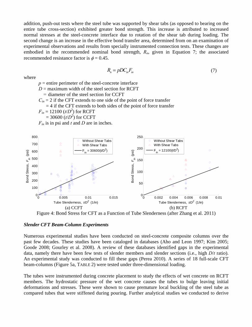
Qrt = required shear strength Composite Seismic Provisions The first edition of the AISC Seismic Specification published in 1992 did not address the design of composite systems. Subsequent editions in 1997, 2002, and 2005 included composite systems in Part II of the specification. In the 2010 edition of the Seismic Specification, Part II has been eliminated and both steel and composite lateral force resisting systems have been integrated in the main provisions (Figure 1). Composite systems, for example special moment frames with CFT or steel reinforced concrete (SRC) columns, are expected to exhibit overall behavior that is similar to the corresponding structural steel system, since inelastic deformations will occur in much the same way, (i.e., flexural yielding of the girders in moment frames; brace buckling in brace frames) (Malley 2010). Recent technical changes include a requirement that cracked section properties be used in elastic analyses of composite structural systems and an increase in detail of the design requirements for composite systems such that they are consistent with structural steel systems. RECENT RESEARCH ON STEEL-CONCRETE COMPOSITE SYSTEMS Natural Bond Behavior for CFT Members Transfer of stress through natural bond, without the use of steel stud anchors or bearing mechanism, is often the most economical connection detail for CFT columns. Recent work by Zhang et al. (2011) has found current provisions on the natural bond strength to be conservative when compared to available experimental results and proposes new provisions which better capture observed behavior. In the 2010 Specification, a constant critical bond stress is assumed to act over a portion of the steel-concrete interface. Two main changes are proposed. The first is a critical bond stress that varies with tube dimensions and computed from an empirical expression fit to results of push-out tests of circular and rectangular CFT members (Figure 4). As observed in the experimental results, the proposed critical bond stresses are greater for smaller and thicker tubes and smaller for larger and thinner tubes. In
addition, push-out tests where the steel tube was supported by shear tabs (as opposed to bearing on the entire tube cross-section) exhibited greater bond strength. This increase is attributed to increased normal stresses at the steel-concrete interface due to rotation of the shear tab during loading. The second change is an increase in the effective bond transfer area, determined from on an examination of experimental observations and results from specially instrumented connection tests. These changes are embodied in the recommended nominal bond strength, Rn, given in Equation 7; the associated recommended resistance factor is φ = 0.45.
n in inR pDC F= (7) where
p = entire perimeter of the steel-concrete interface D = maximum width of the steel section for RCFT = diameter of the steel section for CCFT Cin = 2 if the CFT extends to one side of the point of force transfer = 4 if the CFT extends to both sides of the point of force transfer Fin = 12100 (t/D2) for RCFT = 30600 (t/D2) for CCFT Fin is in psi and t and D are in inches.
(a) CCFT
(b) RCFT
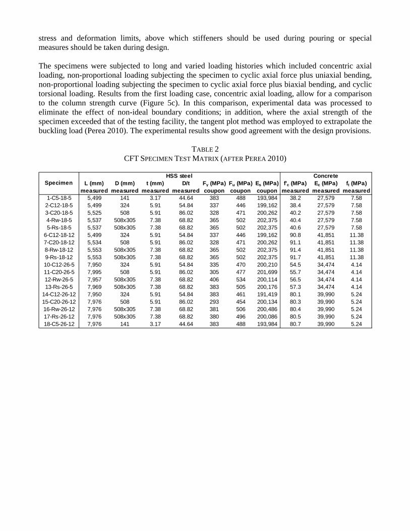
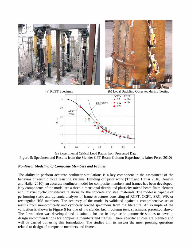
Figure 4: Bond Stress for CFT as a Function of Tube Slenderness (after Zhang et al. 2011) Slender CFT Beam-Column Experiments Numerous experimental studies have been conducted on steel-concrete composite columns over the past few decades. These studies have been cataloged in databases (Aho and Leon 1997; Kim 2005; Goode 2008; Gourley et al. 2008). A review of these databases identified gaps in the experimental data, namely there have been few tests of slender members and slender sections (i.e., high D/t ratio). An experimental study was conducted to fill these gaps (Perea 2010). A series of 18 full-scale CFT beam-columns (Figure 5a, TABLE 2) were tested under three-dimensional loading. The tubes were instrumented during concrete placement to study the effects of wet concrete on RCFT members. The hydrostatic pressure of the wet concrete causes the tubes to bulge leaving initial deformations and stresses. These were shown to cause premature local buckling of the steel tube as compared tubes that were stiffened during pouring. Further analytical studies we conducted to derive
0 0.005 0.01 0.0150
100
200
300
400
500
600
700
800
Tube Slenderness, t/D2 (1/in)
Bon
d S
tress
, F in
(ps
i)
Without Shear TabsWith Shear TabsFin = 30600(t/D2)
0 0.002 0.004 0.006 0.008 0.010
50
100
150
200
250
Tube Slenderness, t/D2 (1/in)
Bon
d S
tress
, F in
(ps
i)
Without Shear TabsWith Shear TabsFin = 12100(t/D2)
stress and deformation limits, above which stiffeners should be used during pouring or special measures should be taken during design. The specimens were subjected to long and varied loading histories which included concentric axial loading, non-proportional loading subjecting the specimen to cyclic axial force plus uniaxial bending, non-proportional loading subjecting the specimen to cyclic axial force plus biaxial bending, and cyclic torsional loading. Results from the first loading case, concentric axial loading, allow for a comparison to the column strength curve (Figure 5c). In this comparison, experimental data was processed to eliminate the effect of non-ideal boundary conditions; in addition, where the axial strength of the specimen exceeded that of the testing facility, the tangent plot method was employed to extrapolate the buckling load (Perea 2010). The experimental results show good agreement with the design provisions.
TABLE 2 CFT SPECIMEN TEST MATRIX (AFTER PEREA 2010)
L (mm) D (mm) t (mm) D/t Fy (MPa) Fu (MPa) Es (MPa) f'c (MPa) Ec (MPa) ft (MPa)measured measured measured measured coupon coupon coupon measured measured measured
Figure 5: S Nonlinear M The ability behavior of and Hajjar 2Key componand uniaxiaperforming rectangular results fromvalidation isThe formuladesign recomwill be carrrelated to de
(a) RC
Specimen and
Modeling of
to perform f seismic for2010), an accnents of the l cyclic consstatic and dyHSS memb
m monotonics shown in Fation was dmmendationried out usinesign of com
CFT Specimen
(c) Experimd Results fro
f Composite
accurate norce resisting curate nonlinmodel are astitutive relaynamic anal
bers. The accally and cyFigure 6 for
developed anns for compong this form
mposite mem
n
ental Critical om the Slend
Members an
onlinear simsystems. B
near model fa three-dimenations for thelyses of framccuracy of thyclically load
one of the nd is suitablosite membemulation. Th
mbers and fram
Load Ratiosder CFT Bea
nd Frames
mulations is auilding off pfor compositnsional distre concrete a
me structureshe model isded specimeslender beamle for use iners and framhe studies ames.
(b) Local Bu
from Processam-Column E
a key compprior work te members ributed plastand steel mas consisting s validated aens from them-column ten large scalemes. Three saim to answ
uckling Obser
sed Data Experiments
ponent in the(Tort and Hand frames
ticity mixed aterials. The
of RCFT, Cagainst a coe literature. ests specimee parametricspecific stud
wer the most
rved during T
s (after Pere
e assessmenHajjar 2010,
has been devbeam finite model is ca
CCFT, SRC,omprehensiv
An examplens presentedc studies to dies are plant pressing q
Testing
a 2010)
nt of the Denavit veloped. element
apable of , WF, or
ve set of le of the d above. develop
nned and questions
(a) Load Case 1
Concentric Loading
(b) Load Case 2
Uniaxial Cyclic (P = 2,669 kN)
(c) Load Case 3
Uniaxial Cyclic (P = 1,334 kN)
(d) Load Case 4
Biaxial Cyclic (P = 2,002 kN)
(e) Load Case 4
Biaxial Cyclic (P = 2,002 kN)
(f) Load Case 4
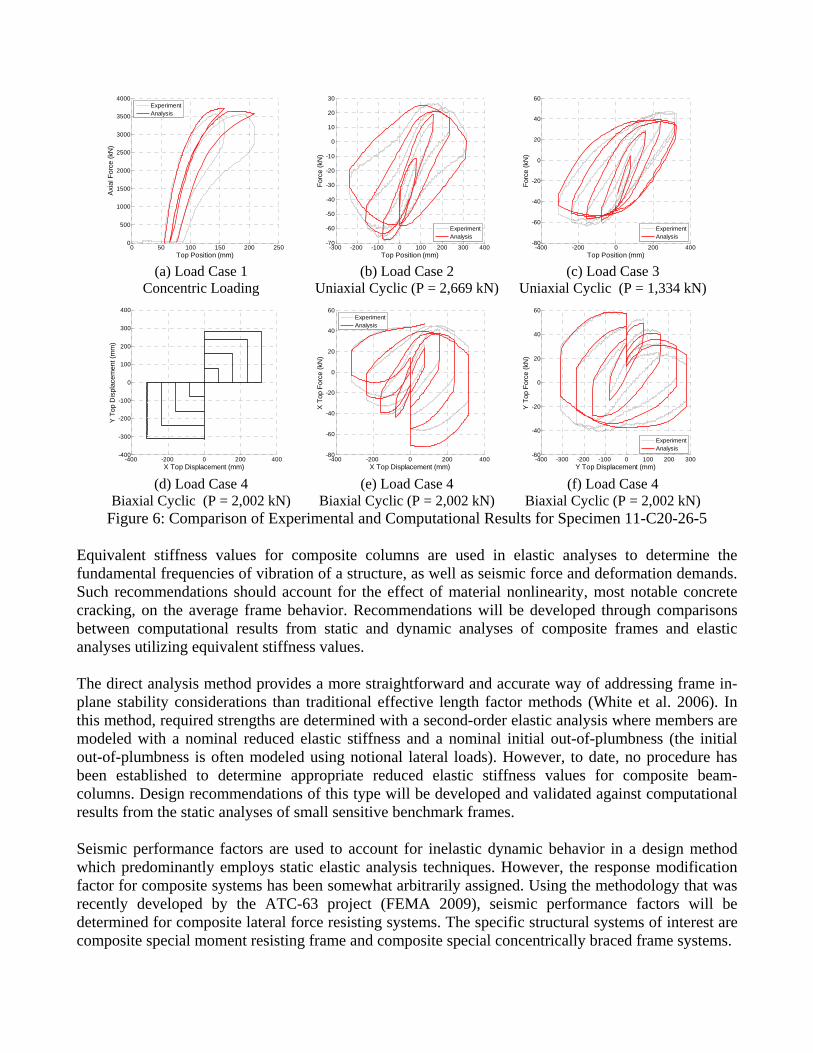
Biaxial Cyclic (P = 2,002 kN) Figure 6: Comparison of Experimental and Computational Results for Specimen 11-C20-26-5
Equivalent stiffness values for composite columns are used in elastic analyses to determine the fundamental frequencies of vibration of a structure, as well as seismic force and deformation demands. Such recommendations should account for the effect of material nonlinearity, most notable concrete cracking, on the average frame behavior. Recommendations will be developed through comparisons between computational results from static and dynamic analyses of composite frames and elastic analyses utilizing equivalent stiffness values. The direct analysis method provides a more straightforward and accurate way of addressing frame in-plane stability considerations than traditional effective length factor methods (White et al. 2006). In this method, required strengths are determined with a second-order elastic analysis where members are modeled with a nominal reduced elastic stiffness and a nominal initial out-of-plumbness (the initial out-of-plumbness is often modeled using notional lateral loads). However, to date, no procedure has been established to determine appropriate reduced elastic stiffness values for composite beam-columns. Design recommendations of this type will be developed and validated against computational results from the static analyses of small sensitive benchmark frames. Seismic performance factors are used to account for inelastic dynamic behavior in a design method which predominantly employs static elastic analysis techniques. However, the response modification factor for composite systems has been somewhat arbitrarily assigned. Using the methodology that was recently developed by the ATC-63 project (FEMA 2009), seismic performance factors will be determined for composite lateral force resisting systems. The specific structural systems of interest are composite special moment resisting frame and composite special concentrically braced frame systems.
0 50 100 150 200 2500
500
1000
1500
2000
2500
3000
3500
4000
Top Position (mm)
Axi
al F
orce
(kN
)
ExperimentAnalysis
-300 -200 -100 0 100 200 300 400-70
-60
-50
-40
-30
-20
-10
0
10
20
30
Top Position (mm)
Forc
e (k
N)
ExperimentAnalysis
-400 -200 0 200 400-80
-60
-40
-20
0
20
40
60
Top Position (mm)
Forc
e (k
N)
ExperimentAnalysis
-400 -200 0 200 400-400
-300
-200
-100
0
100
200
300
400
X Top Displacement (mm)
Y T
op D
ispl
acem
ent (
mm
)
-400 -200 0 200 400-80
-60
-40
-20
0
20
40
60
X Top Displacement (mm)
X T
op F
orce
(kN
)
ExperimentAnalysis
-400 -300 -200 -100 0 100 200 300-60
-40
-20
0
20
40
60
Y Top Displacement (mm)
Y T
op F
orce
(kN
)
ExperimentAnalysis
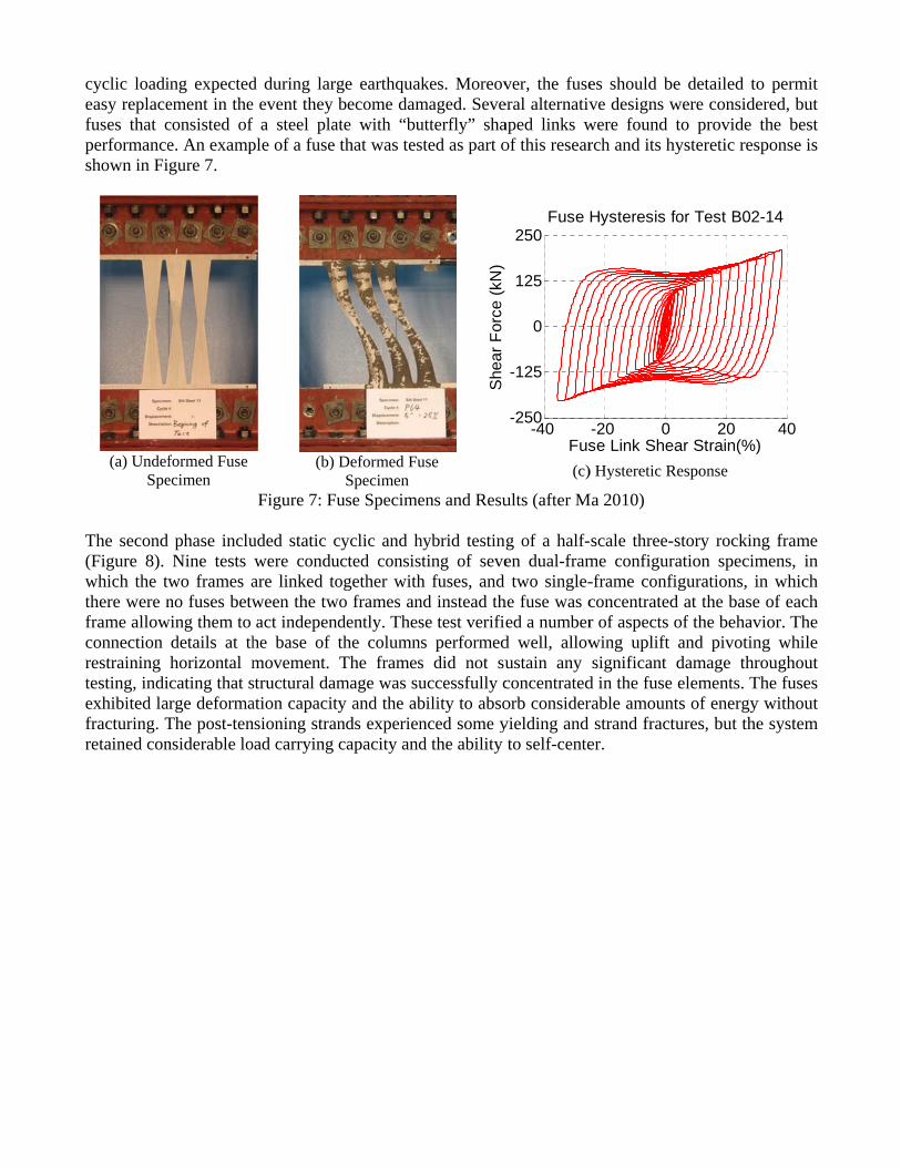
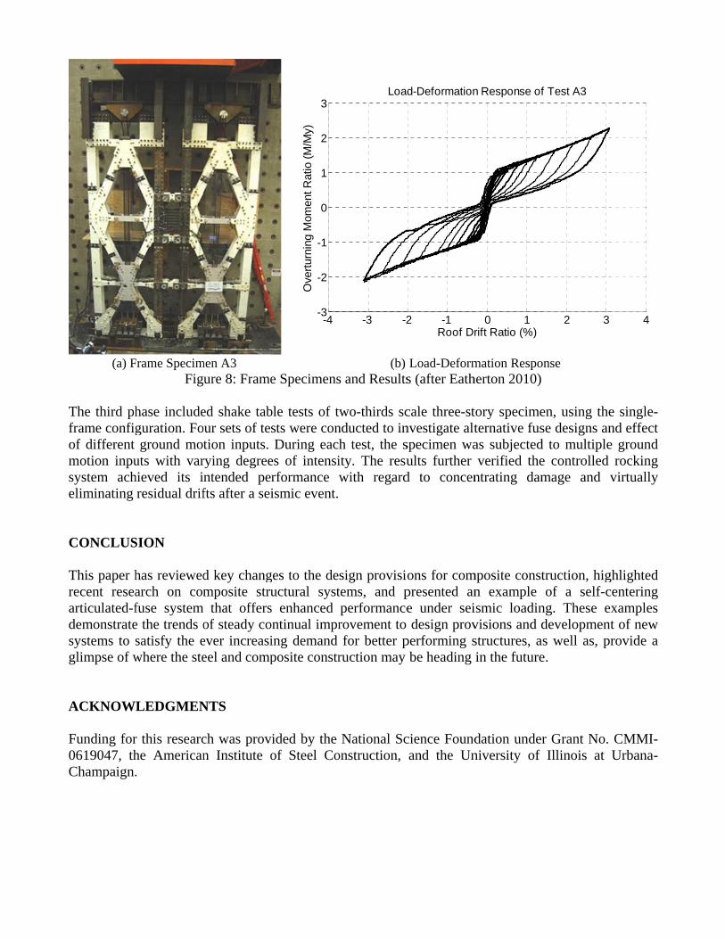
SELF-CENTERING ARTICULATED-FUSE SYSTEMS A natural outcome of the rising popularity of performance based design is that some building owners will show interest in and select structural systems that offer higher levels of performance. As the demand for high performance systems increases, opportunities arise for the development of innovative structural systems. One aspect that owners have shown an interest in is the state of the building and its reparability after a major seismic event. Traditional seismic force resisting systems will often experience inelastic action throughout the structure during a large earthquake, which results in residual drifts and distributed damage that is difficult and costly to repair. Thus, the possibility of a structure that concentrates seismic damage in replaceable elements or that does not exhibit residual drifts after an earthquake is attractive. Three behavioral or structural features not typically present in traditional structural systems have been identified as potentially beneficial to a building seismic performance. These are: rocking, self-centering, and the use of articulated replaceable energy-dissipating structural fuses. A wide variety of research has been carried out to characterize the behavior of structural systems with combinations of these features. Recent studies have been conducted on rocking behavior in concrete structures (Holden et al. 2003; Ajrab et al. 2004; Lu 2005; Palermo et al. 2007), masonry structures (Ma et al. 2006), and steel structures (Ikenaga et al. 2006; Midorikawa et al. 2006; Pollino and Bruneau 2008). Self-centering forces have been identified in many of these studies coming from various sources, including vertical post-tensioning or column base connections designed specifically to provide self-centering forces but also the rotational stiffness of beams that frame in out-of-plane of the uplifting side of the wall. Horizontally post-tensioned moment frame systems have also been developed (Shen and Kurama 2002; Christopoulos et al. 2002; Garlock et al. 2005). For these systems, during a seismic event, the beam rotates relative to the column, opening a gap between the beam flange and the column and the post-tensioning provides a restoring force to return the beam to flush. Many elements within structural systems are capable of dissipating energy during a seismic event, though inelastic deformation, viscous forces, friction, etc.. Structural fuses, according to one definition, are replaceable elements that are designed such that all structural damage is concentrated in this element, allowing the primary structure to remain elastic (Vargas and Bruneau 2009). Such elements would clearly expedite the repair and return to service of a building following a major seismic event. Controlled Rocking System The controlled rocking system for steel-framed buildings combines the three features to provide a superior performance during seismic events and virtually eliminate residual drift. The system consists of steel frames that remain essentially elastic and are allowed to rock about the column bases. The specially designed column base details permit column uplift while restraining horizontal motion with bumpers or an armored foundation trough. The configuration in Figure 7b uses two side-by-side frames, although alternative configurations with single frames have also been investigated. Vertical post-tensioning strands provide self-centering forces. The strands are initially stressed to less than half of their ultimate strength, so as to permit additional elastic straining when the frames rock. Replaceable energy dissipating elements act as structural fuses that yield, absorb energy, and limit the forces imposed on the rest of the structure. In Figure 7b the fuses are configured as yielding shear elements between the two frames. Research has been conducted (Eatherton 2010a, 2010b; Ma 2010a, 2010b) to develop this system, assess its performance, and provide design recommendations. Experimental work consisted of three phases. The first phase included component tests of the energy dissipating fuses. Fuses used in this system should have sufficient ductility and toughness so that they can dissipate energy throughout the
cyclic loadieasy replacefuses that cperformanceshown in Fi
(a) UndefSpe
The second (Figure 8). which the twthere were nframe allowconnection restraining testing, indiexhibited lafracturing. Tretained con
ing expectedement in theconsisted of e. An exampgure 7.
formed Fuse ecimen
phase incluNine tests
wo frames ano fuses betw
wing them to details at thhorizontal mcating that s
arge deformaThe post-tennsiderable lo
d during large event they f a steel plaple of a fuse
(b)
Figure 7: Fu
uded static cwere conduare linked toween the twact indepen
he base of movement. structural damation capacitnsioning stranoad carrying
ge earthquakbecome dam
ate with “buthat was tes
Deformed FuSpecimen
use Specime
cyclic and hucted consisogether with
wo frames andently. Thesthe columnsThe framesmage was suty and the abnds experiencapacity and
kes. Moreovmaged. Seveutterfly” shasted as part o
use
ens and Resu
hybrid testingting of seve
h fuses, and nd instead thse test verifies performeds did not suuccessfully cbility to absonced some yd the ability
She
ar F
orce
(kN
)
ver, the fuseeral alternativaped links wof this resear
(c)
ults (after M
g of a half-en dual-framtwo single-
he fuse was ced a number
d well, allowustain any concentratedorb consideryielding and to self-cente
-40-250
-125
0
125
250Fuse
Fus
es should beve designs w
were found rch and its h
) Hysteretic R
Ma 2010)
scale three-me configur-frame conficoncentratedr of aspects owing uplift significant
d in the fuse rable amount
strand fracter.
-20 0
Hysteresis f
se Link She
e detailed towere consideto provide
hysteretic res
Response
story rockinration specimfigurations, id at the baseof the behavand pivotindamage threlements. Tts of energytures, but the
20
for Test B02
ar Strain(%)
o permit ered, but the best
sponse is
ng frame mens, in in which e of each vior. The ng while roughout
The fuses y without e system
40
2-14
)
(a) F
The third phframe configof different motion inpusystem acheliminating CONCLUS This paper hrecent reseaarticulated-fdemonstratesystems to sglimpse of w ACKNOW Funding for0619047, thChampaign.
Frame SpecimFig
hase includeguration. Foground mo
uts with varhieved its iresidual drif
SION
has reviewedarch on comfuse systeme the trends osatisfy the ewhere the ste
LEDGMEN
r this researche American.
men A3 ure 8: Frame
ed shake tabour sets of tetion inputs. rying degreentended perfts after a sei
d key changmposite stru
that offersof steady coever increasieel and comp
NTS
ch was provn Institute o
e Specimens
ble tests of tsts were conDuring each
es of intensirformance wismic event.
ges to the deuctural systs enhanced ontinual impring demand posite constr
vided by the of Steel Co
-4-3
-2
-1
0
1
2
3
Ove
rturn
ing
Mom
ent R
atio
(M/M
y)
(b) s and Results
wo-thirds scnducted to inh test, the sity. The resuwith regard
sign provisitems, and pperformancerovement to for better p
ruction may
National Sconstruction,
-3 -2
Loa
Load-Deforms (after Eath
cale three-stnvestigate altspecimen waults further d to concen
ons for compresented ane under sei design prov
performing sbe heading
cience Foundand the Un
2 -1
d-Deformation
Roof Dr
mation Respoherton 2010)
tory specimeternative fusas subjectedverified the
ntrating dam
mposite constn example ismic loadinvisions and dstructures, ain the future
dation underniversity of
0 1
n Response of
rift Ratio (%)
onse
en, using these designs and to multiplee controlled mage and v
truction, higof a self-c
ng. These edevelopments well as, pr
e.
r Grant No. Illinois at
2 3
f Test A3
e single-nd effect e ground
rocking virtually
ghlighted centering xamples t of new rovide a
CMMI-Urbana-
4
REFERENCES Aho, M. F., and Leon, R. T. (1997). “A Database for Encased and Concrete-Filled Columns,” Report
No. 97-01, School of Civil and Environmental Engineering, Georgia Institute of Technology, Atlanta, Georgia.
Ajrab, J. J., Pekcan, G., and Mander, J. B. (2004) “Rocking Wall-Frame Structures with Supplemental Tendon Systems” ASCE Journal of Structural Engineering, Vol. 130, No. 6.
American Concrete Institute Committee 318 (ACI 318). Building Code Requirements for Structural Concrete (ACI 318-08) and Commentary (ACI 318R-08), American Concrete Institute, Farmington Hills, Michigan.
American Institute of Steel Construction (AISC) (1936). Specification for the Design, Fabrication and Erection of Structural Steel for Buildings, American Institute of Steel Construction, Chicago, Illinois.
American Institute of Steel Construction (AISC) (1986). Load and Resistance Factor Design Specification for Structural Steel Buildings, American Institute of Steel Construction, Chicago, Illinois.
American Institute of Steel Construction (AISC) (2005). Specification for Structural Steel Buildings, ANSI/AISC 360-05, American Institute of Steel Construction, Chicago, Illinois.
American Institute of Steel Construction (AISC) (2010a). Specification for Structural Steel Buildings, ANSI/AISC 360-10, American Institute of Steel Construction, Chicago, Illinois.
American Institute of Steel Construction (AISC) (2010b). Seismic Provisions for Structural Steel Buildings, ANSI/AISC 341-10, American Institute of Steel Construction, Chicago, Illinois.
Christopoulos C., Filiatrault A., Uang C.-M., And Folz B. (2002) “Posstensioned Energy Dissipating Connections for Moment-Resisting Steel Frames,” ASCE Journal of Structural Engineering, Vol. 128, No. 9, pp 1111-1120.
Denavit, M. D. and Hajjar, J. F. (2010). “Nonlinear Seismic Analysis of Circular Concrete-Filled Steel Tube Members and Frames,” Report No. NSEL-023, Newmark Structural Laboratory Report Series (ISSN 1940-9826), Department of Civil and Environmental Engineering, University of Illinois at Urbana-Champaign, Urbana, Illinois, March.
Eatherton, M. R. (2010a). “Large-Scale Cyclic and Hybrid Simulation Testing and Development of A Controlled-Rocking Steel Building System with Replaceable Fuses,” Ph.D. Dissertation, Department of Civil and Environmental Engineering, University of Illinois at Urbana-Champaign, Urbana, Illinois.
Eatherton, M., Hajjar, J. F., Deierlein, G. G., Ma, X., and Krawinkler, H. (2010b). “Hybrid Simulation Testing of a Controlled Rocking Steel Braced Frame System,” Proceedings of the 9th National Conference on Earthquake Engineering, Rathje, E. M. and Atkinson, G. A. (eds.), Toronto, Canada, July 12-14, 2010, Earthquake Engineering Research Institute, Oakland, California.
Federal Emergency Management Agency (FEMA). (2009). Quantification of Building Seismic Performance Factors, FEMA P695, Washington, D.C.
Garlock, M., Ricles, J. M., and Sause, R. (2005) “Experimental Studies of Full-Scale Posttensioned Steel Connections” ASCE Journal of Structural Engineering, Vol. 131, No. 3.
Goode, C. D. (2008). “Composite Columns - 1819 Tests on Concrete-Filled Steel Tube Columns Compared with Eurocode 4.” The Structural Engineer, Vol. 86, No. 16, pp. 33-38.
Gourley, B. C., Tort, C., Denavit, M. D., Schiller, P. H., and Hajjar, J. F. (2008). “A Synopsis of Studies of the Monotonic and Cyclic Behavior of Concrete-Filled Steel Tube Beam-Columns,” Report No. NSEL-008, Newmark Structural Laboratory Report Series (ISSN 1940-9826), Department of Civil and Environmental Engineering, University of Illinois at Urbana-Champaign, Urbana, Illinois, April.
Griffis, L. G. (1992). “Load and Resistance Factor Design of W-Shapes Encased in Concrete,” Design Guide 6, AISC, Chicago, IL.
Griffis, L. G. (2005). “Composite Design Provisions 2005 AISC Specification for Steel Buildings,” Proceedings of the 2005 Structures Congress, New York, New York, April 20-24, 2005, ASCE, Reston, Virginia.
Hajjar, J. F. and Gourley, B. C. (1996). “Representation of Concrete-Filled Steel Tube Cross-Section Strength,” Journal of Structural Engineering, ASCE, Vol. 122, No. 11, pp. 1327-1336.
Holden, T., Restrepo, J., and Mander, J. B. (2003) “Seismic Performance of Precast Reinforced and Prestressed Concrete Walls” ASCE Journal of Structural Engineering Vol. 129, No. 3, pp 286-296.
Ikenaga, M.; Nagae, T., Nakashima, M., and Suita, K. (2006) “Development of Column Bases Having Self-Centering and Damping Capability” Proceedings of the Fifth International Conference on Behaviour of Steel Structures in Seismic Areas STESSA 2006, Yokohama, Japan, August 14-17.
Kim, D. K. (2005). “A Database for Composite Columns,” M.S. Thesis, School of Civil and Environmental Engineering, Georgia Institute of Technology, Atlanta, Georgia.
Leon, R. T., Kim, D. K., and Hajjar, J. F. (2007). “Limit State Response of Composite Columns and Beam-Columns Part 1: Formulation of Design Provisions for the 2005 AISC Specification.” Engineering Journal, AISC, Vol. 44, No. 4, pp. 341-358.
Leon, R. T., and Hajjar, J. F. (2008). “Limit State Response of Composite Columns and Beam-Columns Part II: Application of Design Provisions for the 2005 AISC Specification.” Engineering Journal, AISC, Vol. 45, No. 1, pp. 21-46.
Lu, Y. (2005) “Inelastic Behaviour of RC Wall-Frame With a Rocking Wall and its Analysis Incorporating 3-D Effect” The Structural Design of Tall and Special Buildings, Vol. 31, pp 79-97.
Ma, Q. T., Wight, G.D., Butterworth, J.W., and Ingham, J.M. (2006) “Assessment of Current Procedures for Predicting the In-Plane Behaviour of Controlled Rocking Walls” Proceedings of the 8th U.S. National Conference on Earthquake Engineering, San Francisco, CA, April 18-22, Paper No. 654.
Ma, X. (2010a). “Seismic Design and Behavior of Self-Centering Braced Frame with Controlled Rocking and Energy Dissipating Fuses,” Ph.D. Dissertation, Stanford University, Palo Alto, California.
Ma, X., Deierlein, G. G., Eatherton, M., Krawinkler, H., Hajjar, J. F., Takeuchi, T., Kasai, K., Midorikawa, M., and Hikino, T. (2010b). “Large-Scale Shaking Table Test of Steel Braced Frame with Controlled Rocking and Energy-Dissipating Fuses,” Proceedings of the 9th National Conference on Earthquake Engineering, Rathje, E. M. and Atkinson, G. A. (eds.), Toronto, Canada, July 12-14, 2010, Earthquake Engineering Research Institute, Oakland, California.
Malley, J. O. (2010). “The AISC Seismic Provisions: Past, Present and Future,” Proceedings of the 2010 NASCC: The Steel Conference, Orlando, Florida, May 12-15, AISC, Chicago, Illinois.
Midorikawa, M., Azuhata, T., Ishihara, T., and Wada, A. (2006) “Shaking Table Tests on Seismic Response of Steel Braced Frames with Column Uplift” Earthquake Engineering and Structural Dynamics, No. 35, pp 1767-1785.
Palermo, A., Pampanin, S., Marriott, D. (2007) "Design, Modeling, and Experimental Response of Seismic Resistant Bridge Piers with Posttensioned Dissipating Connections" ASCE Journal of Structural Engineering, Vol. 133, No. 11, 2007, pp 1648-1661.
Pallarés, L., and Hajjar, J. F. (2010a). “Headed Steel Stud Anchors in Composite Structures, Part I: Shear.” Journal of Constructional Steel Research, Vol. 66, No. 2, pp. 198–212.
Pallarés, L., and Hajjar, J. F. (2010b). “Headed Steel Stud Anchors in Composite Structures, Part II: Tension and Interaction.” Journal of Constructional Steel Research, Vol. 66, No. 2, pp. 213–228.
Perea, T. (2010). “Analytical and Experimental Study on Composite Concrete-Filled Steel Tube Beam-Columns,” Ph.D. dissertation, School of Civil and Environmental Engineering, Georgia Institute of Technology, Atlanta, Georgia.
Pollino, M., and Bruneau, M. (2008) Analytical and Experimental Investigation of a Controlled Rocking Approach for Seismic Protection of Bridge Steel Truss Piers, Technical Report MCEER-08-0003.
Shen, Q., and Kurama, Y. C. (2002) “Nonlinear Behavior of Posttensioned Hybrid Coupled Wall Subassemblages” ASCE Journal of Structural Engineering, Vol. 128, No. 10.
Tort, C. and Hajjar, J. F. (2010). “Mixed Finite-Element Modeling of Rectangular Concrete-Filled Steel Tube Members and Frames under Static and Dynamic Loads,” Journal of Structural Engineering, ASCE, 136(6), 654-664.
Varma, A.H. and Zhang, K. (2009), “Slenderness Limits for Noncompact/Slender Filled Members,” Bowen Laboratory Report No. 2009-01, School of Civil Engineering, Purdue University, West Lafayette, IN, August.
Vargas, R., and Bruneau, M. (2009) “Analytical Response and Design of Buildings with Metallic Structural Fuses. I” Journal of Structural Engineering, ASCE, Vol. 135, No. 4, pp. 386-393.
White, D. W., Surovek, A. E., Alemdar, B. N., Chang. C.-J., Kim, Y. D., and Kuchenbecker, G. H. (2006). “Stability Analysis and Design of Steel Building Frames Using the 2005 AISC Specification,” Steel Structures, Vol. 6, pp. 71-91.
Zhang, J., Denavit, M. D., Hajjar, J. F., and Lu, X. (2011). “Bond Behavior of Concrete-Filled Steel Tube (CFT) Structures,” Engineering Journal, AISC, submitted for publication.