J-1 e Hud son 5344 as streamlined for the " Commodore Vanderbilt " in Decemb er, 1934. Ca rl F . Ka nt o la NEW YORK CENTRAL STREAMLINED STEAM LOCOMOTIVES Assistant Engin ee r, Equipm ent Engineering Depa rtm ent The Commodore Vanderbilt Locomntive On Decem ber 27, 1934 th e "Wor ld 's Firs t-P owered S tr ea m- lined Steam Loco moti ve" was ex hibited at th e Gr and Ce ntr al Te rmina l. The New York Times and o th er newspa per s gave it a hea dlined ar ticle with ph ot og ra ph s a nd pr oclaimed it to be a great d ay for th e railr oa ds and th e beg innin g of a new era in lo co motive d es ig n. Here is the ins id e st ory of h ow it happened. It was early in th e yea r 1934 and th e countr y was co min g o ut of th e g rea t d epression years. Th e railr oa ds had also fe lt th e eco nomic distress and so me thin g was need ed to ins pir e m ore int erest in th e railr oa d s. Strea mlinin g seemed to be th e co min g thing in indu strial d es ig n, so why not tr y it on the railr oa d? Since I was a bac helor at that tim e, with free time in th e evenings, I dr ew up a penc il sketch of a streamline design for a Hud so n type loco motive. At th e office we prese nt ed th e sketch to Mr. Paul W. Kie fer, Chief Engineer of Motive Power and Rolling St ock , who was quit e taken with th e id ea. He th en showed it to Mr. F. E. Wi lli amso n, Pres id ent of th e New York Ce ntral. Mr. Willia mso n th ought it wo uld be very goo d publi city for the railr oa d a nd gave us th e a uth ority to p ro mptl y pr oceed with th e s tr eamline project. Hav ing sta rt ed th e id ea, it became my assig nment to . dr aw up th e wor king plans from my preliminary sketch. Work was st a rt ed, and in two mo nth s th e plans were dr awn a nd blu e print ed ready 8 for co ns tru c tion . Th e pres id ent's of fi ce advised that the loco m o- tive should be named th e " Co mm odore Vanderbilt ," a ft er the founder of th e New York Ce ntr al System. A cast a luminum New York Ce ntr al oval was designed fo r the fro nt of th e locomoti ve . Th e 16-gauge st ee l co wling ove r th e bo il er and front end was designed to be s upp orted on li ght weight struc tur al steel angle a tt ac hed to th e bo il e r. Th e thr ottle ro ds and various pipin g we re co ncealed und er the cow ling. Recessed openings were pro v id ed for the bell, whistle, safe ty va lves a nd l ow wat er a la rm . Th e f ront end cow li ng had a hin ged d oo r for access to the smokeb ox insp ection d oo r, a nd a lso pr ov id ed access to the two cross-c omp o und a ir co m- pressors and th e turb o-electric generator which was relocated on th e f ro nt pilot beam. Access to the dr op-type front co upler and air hoses was had by removing a co wling pane l. A smoke lifter was built into the design by formin g an air scoo p around the smoke st ac k, with h ea d end air ente rin g th e scoo p throu gh a grill in fro nt of th e scoo p. An a dditi onal smoke -li ftin g fea tur e was des ig ned by fo rmin g scoo ps bac k of th e ri g ht and le ft s id e runnin g b oar d step s. Hea d end air entered these scoo ps a nd was dir ected up wa rd thr ough grills in th e runnin g b oa rd s a nd a lo ng eac h si de of th e bo il er cowlin g. The s id e pa nels ex te nd ed fo rward of the steps to make more effective scoo ps. The 16-gauge steel side panels were designed with a long swee pin g a rch ove r th e engine tru ck and dri ving wheels. A fi xe d section of th ese panels extended ab ove th e runnin g boa rd s. The lower side panels were in several sections, and were hinged at th e
Transcript
J-1 e Hudson 5344 as streamlined fo r the "Commodore Vanderbilt" in December, 1934.
Ca rl F . Ka nt o la
NEW YORK CENTRAL STREAMLINED STEAM
LOCOMOTIVES Assista nt Engineer, Equipment Engineering Depa rtment
The Commodore Vanderbilt Locomntive
On Decem ber 27, 1934 th e " World 's F irs t-Powered S trea mlined Stea m Loco moti ve" was ex hibited a t th e Gra nd Ce ntra l Termina l. T he New York Times a nd o ther newspa pers gave it a headlined article with photographs a nd procla imed it to be a grea t day for the ra ilroads a nd th e beginning of a new e ra in loco motive des ign.
Here is th e ins id e story of how it ha ppened . It was ea rly in th e yea r 1934 a nd the country was co ming out of the g reat d epressio n yea rs. The ra ilroads had a lso fe lt th e eco no mic dist ress a nd so mething was need ed to inspire more inte res t in th e railroads. St rea mlining seemed to be the co ming thing in industrial d es ig n, so why not try it on the ra ilroad?
S ince I was a bachel o r a t tha t time, with free time in the even ings, I drew up a pencil sketch of a st rea mlin e d es ign fo r a Hudso n type loco moti ve. At the o ffice we prese nted the sketch to Mr. Pa ul W. Kiefer, C hief Engineer of M otive Power a nd Rolling Stock , who was quite ta ken with the id ea. He then showed it to Mr. F. E. Willia mso n, Pres id ent of the New York Ce ntral. M r. Willia mso n th o ught it wo uld be very good publicity fo r th e ra ilroad a nd gave us the a uth orit y to p ro mptly proceed with the strea mline project.
Having sta rted the id ea , it beca me my ass ignment to .draw up the working pla ns from my prelimina ry sketch. Work was sta rted , a nd in two months the pla ns were dra wn a nd blueprinted ready
8
for co nstruction . The pres id ent 's offi ce advised th at th e loco motive sho uld be na med the "Comm od o re Va nd erbilt ," a ft er th e fo und er of th e New Yor k Ce ntra l System. A cast a luminum New York Centra l oval was designed fo r the front of the locomoti ve. The 16-ga uge steel co wling ove r th e bo iler a nd front e nd was d esigned to be supp o rted o n li ght weight st ructura l stee l a ngle attached to the bo iler. The thro ttle rods a nd va ri ous piping we re concea led und er th e cowling. Recessed openings were provid ed for th e bell, whistle, safety va lves a nd low water a la rm. The front end cow li ng had a hinged d oo r fo r access to the smo kebox inspecti o n d oo r, a nd a lso provid ed access to th e two cross-compo und a ir co mpressors a nd th e turb o-electric ge nera to r which was reloca ted o n the fro nt pilot bea m. Access to th e dro p-type front co upler and a ir hoses was had by removing a co wling pa nel. A smoke lifter was built int o the des ign by forming a n a ir scoo p a round th e smo ke stac k, with head end a ir entering th e scoo p through a grill in fro nt of the scoo p. An additi ona l smoke-li fting fea ture was desig ned by fo rming scoo ps bac k of the ri ght a nd left sid e running board steps. Head end a ir entered th ese scoo ps a nd was directed upwa rd thro ugh grills in th e running boa rd s a nd a lo ng each s ide of th e bo iler cowling. T he s id e pa nels ex tend ed fo rward of th e steps to make more effective scoops.
T he 16-ga uge steel side pa nels were des igned with a lo ng sweeping a rch over th e engine truc k a nd driving whee ls. A fi xed secti on of these pa nels ex tend ed a bove the running boa rd s. T he lower side pa nels were in severa l secti o ns, and were hinged a t the
running boards so that they could be raised for maintenance a nd inspection . When closed they were supported on structural frames and locking devices were provided to secure them to the frames .
Covering the coal space on the tender presented a problem . However, we designed a cover consisting of four longitudinal panels welded to longitudinal rods which ran the length of the coal space. These rods extended beyond the front of the coal space doors a nd were provided with levers to swing the covers to a vertical position for loading coal.
The gangway between engine and tender was closed off with curtains. We designed canvas side curtains which operated on vertical rollers mounted to the rear edges of the cab. The free edges of these curta ins were attached to the tender by slotted fixtures. A heavy canvas curtain attached to the roof contour was provided to enclose the space between the cab roof and the tender coal space covers.
The painting specifications called for black metal lacquer on the engine and tender with white letteri ng and striping.
Model tests in a wind tunnel indicated tha t this streamlining would reduce headend air resistance by 30 percent at speeds of from 60 to 80 miles per hour.
Six U.S. patents were later granted covering various features of the completed des ign.
About November I, 1934 I went to Wes t Albany Shops where the work was to be done, to direct the construction and to stay until the work was completed. With the wonderful cooperation of th e locomotive shop superintendent, Mr. John Parsons , a real gentleman; Mr. Frank McMahan, the shop engineer; and all others concerned, th e job went along well. As it happened , although we did not know it at the time, we won the race to complete the first streamliner. At the same time the American Locomotive Co. in Schenectady was building the Milwaukee Road's first streamlined steam locomotive, but this was not completed until sometime in 1935.
A Hudson type 4075 horsepower passenger locomotive with 79" drivers , class J le #5344 was just being outshopped , so this was picked for the streamline project.
The streamlining was completed on December 14, 1934. Photographs were taken outside of the shops with the modern 228-ton streamliner posed alongside of the 7 Y2 ton "Dewitt Clinton," replica of the New York Central's first locomotive in 1831.
The 5344 had roller bearings o-n all of the driver axles and on the engine truck axles. As first outshopped , the driving wheel centers were of the original spoke type, but on September 12, 1935 they were replaced with solid type driving wheel centers. At this same time Timken roller bearing main and side rods were installed , and this was the first New York Central locomotive to be so equipped.
After a trial run at Albany the 5344 "Commodore Vanderbilt" proceeded to Harmon, N.Y. Here it was prepared for exhibit at Grand Central. In order to clear the overhead third rail for electric locomotive pantographs the overall height had to be reduced. This was accomplished by using smaller gibs in the spring hangers, thus lowering the engine about two inches, and to further lower it to the boiler was filled to capacity. It was then towed to Grand Central Terminal by an electric locomotive with light cars between the locomotives to distribute the weight on the Harlem River bridge and Park Avenue viaduct. It was a close operation, but the trip into the Park Avenue tunnel was made with a scant two inches of clearance from the overhead rail.
After the exhibit at Grand Central Terminal the locomotive was returned to Harmon roundhouse where the standard spring hanger gibs were replaced. The locomotive was then fired up and sent on a exhibition tour of the principal cities on the New York Cenlral. Following the tour, it was placed in regular 20th Century service on Lines West , so that it could be seen by the public and travelers. ·
9
As had been predicted, this first streamliner was followed up by similar designs on many other railroads in the United States and Canada.
After the delivery of class J3a Hudsons #5445-5454 with modified streamlining in 1938, #5344 "Commodore Vanderbilt" lost her distinctive shroud and was restreamlined to resemble the later ten locomotives.
The Rexall Streamlined Convention Train
During his travels, Mr. Louis K. Liggett, president of the United Drug Company had occasionally seen our streamlined "Commodore Vand.erbilt" locomotive and had been very much impressed. One day it occurred to him that it would be a great idea to have their own streamlined train to travel over the country. Their personnel convention meetings could be held on this train at the various cities, rather than to have all I 0,000 people come to a central convention, and in addition the train could be a traveling display of their products .
Mr. Liggett contacted our president, Mr. F. E. Williamson, about having a streamlined locomotive like the "Commodore Vanderbilt" for the proposed train. Mr. Williamson agreed to furnish the locomotive, and Mr. Liggett made arrangements with the Pullman Company to furnish 12 cars for the train.
The big question was could we furnish the locomotive in t11e.30 days that was specified for completion. Anyhow, smce I had recently drawn the plans for the "Commodore Vanderbilt" and had directed the construction, this project was assigned to me.
On March I, 1936 I went to our West Albany Shop with a set of the "Commodore Vanderbilt" prints. However, they were for reference only as they were for a Hudson type locomotive. A fast freight locomotive was to be streamlined for the Rexall train as it would be pulling a 12-car train over the steep grades of the western mountains.
Locomotive #2873, a class L2c Mohawk with 69" drivers and with roller bearings on all axles except the engine truck and with trailing truck booster was selected for this project as it had been recently outshopped but had been in service long enough to be broken in . Since #2873 was a freight locomotive steam heat and train air signal equipment had to be installed , and since some western railroads burned oil the locomotive had to be converted to an oil burner.
As it developed, this turned out to be not only a 30 day, but a 30 day and 30 night project. The shop management and personnel were very cooperative and with the help of Frank McMahan, the shop engineer, we covered the day trick and the second trick to expedite the project. Each night I would mark up my set of prints to suit the dimensions of the L2locomotive and used them for the next day's production. Some of the work was just a custom made job to suit conditions. The paint shop with their usual skill and artistic ability did a beautiful job of painting it with the Rexall blue and a wide white stripe on the side of the locomotive panel and the tender. This was to match the colors the stripe on the 12-car train. "The Rexall Train" was lettered in blue on the white stripe of the locomotive. We also had an aluminum casting made of the "New York Central" oval and placed on the front cowling below the headlight. There were no other outward signs of the New York Central. The locomotive number was stencilled on the back wall of the cab.
Mr. Bert Daniels, road foreman of the Mohawk Division, was assigned to travel with this locomotive on the tour. He took a good supply oftools, grease, lubrication, etc. along. As he related later, his greatest concern was the friction bearings on the engine truck axles which required frequent inspection and maintenance.
On Sunday morning March 22, 1936, with a full tender tank of fuel oil, the locomotive was run down to the Rensselaer, N.Y. yards where we met the special train of Pullman cars. No. 2873 was coupled to the train and pulled out on the B.&A. Division to Boston, Mass. where the tour was to originate. Fuel oil was obtained from tank trucks until we were on the western railroads.
and running gear. left 'ide 'iew ot J-1 e 5344 afte, '''eamtjne 'hmuding wa, appfied in Decem be,, 1934. Note odginat 'Poked d'i'e"
10
---
"Commodore Vanderb ilt" 5344 shows off her new disc drivers, but still no eng ine number is carried below cab windows as was usual N.Y.C. practice.
3/4 rear view of "Commodore Vanderbilt" 5344 shows that no engine number was applied to rear of tender tank, but water and coal capacities were applied.
11
"Commodore Vanderbilt" 5344 and train
\\ ooc o ll' I""' \ H \ 11 ' '' '' lli<.I!I'0\1 1 1 1 I) \ 11 \ 1 LO(O\IOfl\ 1
l iJif ' .
Pcomolional photo showing 5344 complete With disc delve" and mllec beaclng COds. ca,l F. Kantola Collection
12
. . ... - . ~.. . . • ..., l -· --
"Commodore Vanderbilt" 5344 as it appeared at West Albany Shops on September 12, 1935 with streamlined
shrouding removed for application of disc drivers and roller bearing rods. Carl F. Kantola Collection
13
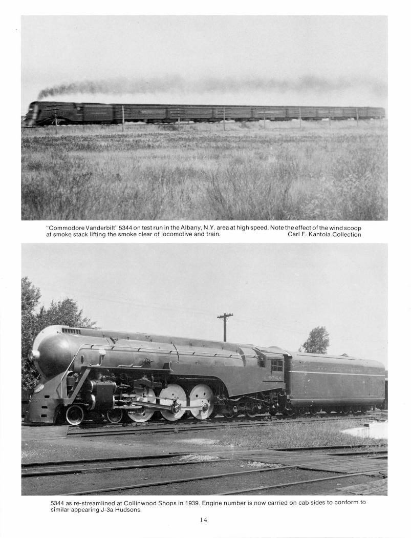
"Commodore Vanderbilt" 5344 on test run in the Albany, N.Y. area at high speed . Note the effect of the wind scoop at smoke stack lifting the smoke clear of locomotive and train . Carl F. Kantola Collection
5344 as re-streamlined at Collinwood Shops in 1939. Engine number is now carried on cab sides to conform to similar appearing J-3a Hudsons.
14
The L-2c locomotive 2873 streamlined for the Rexall train. The cars of the Rexall train had just arrived at Rennselaer, N.Y. from Chicago and are about to depart for Boston behind the 2873. Note the dirt covering the white stripe on the cars, we wiped a corner clean to be sure that it was white. Carl F. Kantola Collection
The Rexall train stops at Green Bay, Wis. on July 3, 1936. The oil-burning 2873 and her 12 car train measured 1080 ft. long and traveled 29,000 miles in 200 cities through the U.S. and Canada serving as a mobile convention center for 10,000 Rexall druggists and 20,000 salespeople.
15 Paul W. Prescott Collection
Front view of the "Rexall Mohawk" 2873 showing air scoops back of side steps and at stack. Carl F. Kantola Collection
16
N.Y.C. L-2c " Mohawk" converted to an oil burner and streamlined for the Rexall train in 1936.
The streamlined 2873 at West Albany, N.Y. in 1936. Note neat, tight fitting diaphram between cab and tender. Did the engine crew have to crawl in and out of the window?
17
•
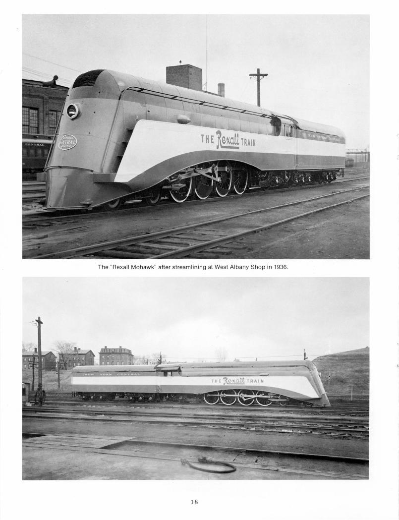
The " Rexall Mohawk" after streamlining at West Albany Shop in 1936.
18
The Rexall train with L-2c 2873 is seen at Syracuse, N.Y. on September 16, 1936. Note the "Rexalllettering applied to the front nose between the headlight and the N.Y.C. oval. George E. Votava Collection
Was this N.Y.C. speed attempt a direct decendant of the same type of "inverted bathtub" shrouding used on the original "Mercury," "Commodore Vanderbilt," and "Rexall" streamlining efforts? The jet powered R.D.C. M-497 is seen at Bryan , Ohio on July 24, 1966. Mrs. Howard W. Ameling, Howard W. Ameling Collection
19
I proceeded to Boston also where final arrangements were made for the 9 month and 29 ,000 mile tour of the United States and parts of Canada. Stops were sc heduled for 200 cities on the tour, which covered 52 railroads. The locomotive and train were placed on exhibit at the South Station in Boston and before leaving on tour on March 28, 1936, the train was christened by Mrs. Minard , a 33-year Rexall employee. Mrs. Minard broke a bottle of champagne on the right side main crank pin of the locomotive, also marking the 33rd anniversary of the United Drug Co. Mr. Liggett stood by.
About 10,000 Rexall druggists and 20,000 Rexall salespeople attended convention meet ings on the train . The Rexall product exhibit was open to the public during th e daytime and was viewed by more than a million- f'leople.
The tra in consisted of twelve cars, a converted baggage car next to the locomotive equipped with a gasoline engine and generator for lighting a nd air conditioning, two sleeping cars for the train staff of 50 people , four cars of Rexa ll exhibits with the regular seats removed , two lecture cars for convention work having folding chairs which could be removed when th e orchestra played for dancing in the evenings, a lounge car, a dining car serving buffet type meals, and fina lly, Mr. Liggett's privat e car. On tour we had orders to keep the locomotive on the train during the daytime exhibits and to head into all terminals so that the streamlined locomotive would be see n by a ll enter ing the train from the sta tion . The locomoti ve would only be removed from the tra in after dark and on those occasions when it was necessa ry to go to a roundhouse for se rvicing. I well remem ber spe nding Easter Sunday on th e locomotive in St , Louis stati on. Bert and I had a grand view of th e g irl s coming onto the train in their Easter finery. And Wichita, Kansa s wh ere we had run through one of the dust storms and nearly ruined the paint job by th e sandblast effect.
I left the train there and didn't see it again until it was in Chicago for mid-tour inspect ion of the locomotive at Englewood roundhouse and the cars at the Pullman Co. From there it went on to complete the tour. All in all it was a successful tour a nd a record for one locomotive to complete without any breakdowns or accidents. For this Bert Daniels deserved a great deal of credit.
The "Mercury streamlined steam locomotives and train
On June 25 , 1936 the streamlined locomotives and cars for the Cleveland-Detroit "Mercury" were completed: the locomotives having been streamlined at the West Albany Shops and the cars a t th e Beec h Grove Shops. This train was to be on a 60 mph schedule with top speeds of 85 mph. One intermediate stop was scheduled at Toledo, Ohio. Service was inaugurated on July 15, 1936.
Two class K5b Pacific type locomotives #4915 and #49 n (originally #6515 and #6517) were streamlined for this trai n. These locomotives had 79" drivers, originally with spoke type centers. These centers were replaced with so lid disc type centers when the locomotives were streamlined. Roller bearings were applied to the engine and tra iling truck axles at this time. but the driver axles retained the original friction bea rings.
Henry Dreyfus, an industrial designer, was credited with the streamline design of these locomotives. However, it will be noted that the design followed that of our two prev ious streamliners very closely , having the smoke lifting devices in the cowling over the boiler and at the running board steps, as well as the raised portion of the side panel s over the driving wh eels a nd the New York Central oval on the front end below th e headlight. The tend er coal space cover and the cab curtains were also similar to our own prev ious designs. One new feature was the illumination of the driving wheels at night, with flood lights located inside the sid e panels.
Christening ceremony for the " Mercury" at Indianapolis, June 25, 1936. The train was christened by Miss Louise Landman, daughter of general passenger traffic manager L. W. Landman, usmg a bottle of champagne from Sandusky , Ohio. Following the ceremony the train was moved to New York for display at Grand Central Term mal , June 28-29, 1936.
20
N.Y.C. K-Sb 4917 shown in James Whitcomb Riley service at Indianapolis, Ind. on November 3, 1941 . Howard W. Ameling Collection
The " Mercury" headed by K-Sb 4-6-2 4917 roars through open country near Cleveland , Ohio in May, 1937. Photo by Andrew Hriz, Bruce Young Collection
21
The train consisted of refurbished commuter cars originally built for service on the Putnam Division. These cars had an arch type roof which readily contributed to the streamline effect when enclosures were ad ded between the cars and at the rear of the locomotive tender. The interiors of the cars were completely remodeled , and tightlock couplers with improved dra ft gears were applied to allow smoother train ha ndling . Large "Winged Mercury" medallions on the sides of the cars at each end add ed a distinctive note to the "Mercury."
(See the "Central Headlight" issue for October, 1972 for additional information on the "Mercury" equipment.)
Streamlined steam locomotives for the 20th Century Limited
The fi rst of fifty new and improved Hudson type passenger locomotives went into service September 7, 1937. These class J3a locomotives were #5405-#5454 a nd were built by the American Locomotive Company at Schenectady, New York .
In 1938 the last ten of this order, #5445-#5454, were completed with a modified st rea mline design. This consisted of a cowling at the top of the boiler enclosing the bell , whistle, safety va lves, low water alarm a nd main turret. The smoke lifting scoop was designed a round the stack. A semi-spherical encl osure covered the front end of the boi ler with the head light located in its center. Below this a skirt with a New York Central oval on it extended down to the bottom of the pilot , covering the drop coupler. A na rrow pa nel extended along the edge of each running board . This panel curved downward bac k of the rear drivers and then extended to the rear of the ca b in a line above the trailing truck . The coal space of the tender was covered a nd the rea r of the tender had a n enclosure to match the enclosu res on the cars. Locomotives a nd tenders were painted light gray to match the color of the train.
All class J3a locomot ives had nickel steel boilers carrying 265 pounds pressure, a nd all axles were roller bearing equipped . The
79" drivers had so lid type · wheel centers and the la s t five locomotives #5450-5454 were equipped with Timken Roller Bearing ma in rods, side rods, a nd crosshead pins. These rods were of lightweight , high tensile steel. The tender capacity was 14.000 gallons of water and 30 tons of coal ( 13.600 gallons of water and 28 tons of coal on the streamlined locomotives). The tenders were equipped with a tight lock coupler and rubber draft gear on the rear to match the car equipment for smoother train ha ndling, and with improved high speed 85 mph water scooops.
The weight of these locomotives was 66.000 lbs. on the engine truck, 196,000 lbs. on the drivers and 98.000 lbs. on the tra iling truck of which 42,500 lbs. was on the front ax le a nd 55,500 lbs. on the rear ax le supporting the booster engine, for a tota l weight of 360,000 lbs. All of these engines were eq uipped with a utomatic train co ntrol, stokers, power reve rse gear, feed water heaters a nd row water alarms, besides the usua l standard eq uipment.
These streamlined locomotives were used on the a ll new 20th Century Limited trai ns which were inaugurated on June 15, 1938.
Streamlined steam locomotives for the Empire State Express
In 1941 two additi onal class J3a Hudso n type loco motives #5426 and #5429 were st rea mlined for the a ll new Empire State Express which made its ina ugural run on December 7, 1941.
This strea mlining was genera lly sim ila r to that which had been a pplied to class J3a loco motives #5445-5454 when they were built in 1938. About the o nly difference in these two engines was that the upper ha lf of the boiler jacket , top cowling a nd front end enclosure was pa inted light a luminum. The lowe r ha lf of the boiler jacket , the front end skirt , and the cylinders were pa inted black as was the lowe r ha lf of the sp herica l smoke box enclosure. The side panels below the running boards were made of fluted sta inless steel and extended a long the lower part of the tender sid es to match th e fluted sides of the Budd-built stai nless steel cars. A clear panel area on the
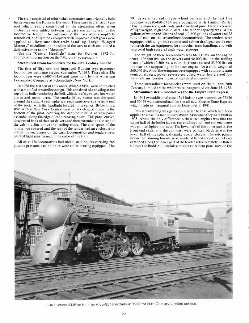
J-3a Hudson 5445 as built by Alco-Schenectady in 1938 for 20th Century Limited service.
22
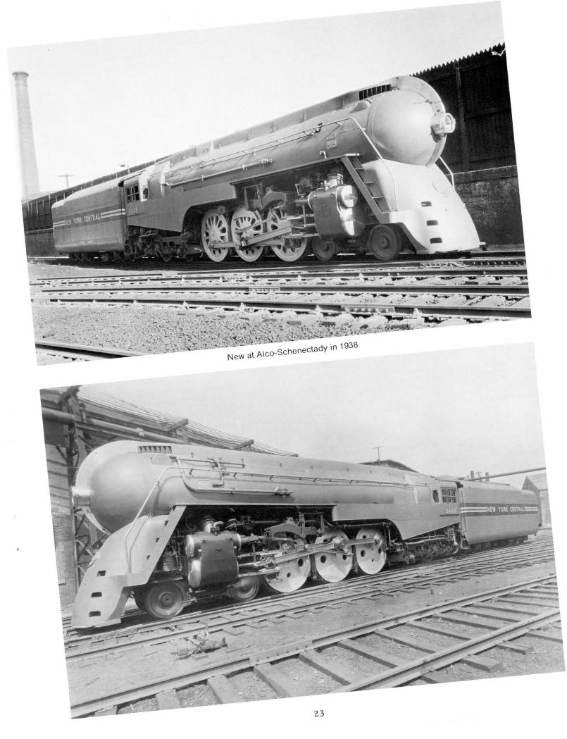
New at Alco-Schenectady in 1938
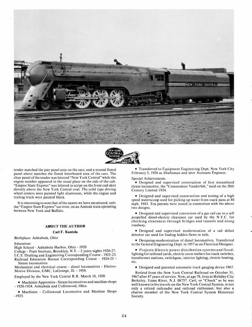
tender matched the pier panel area on the cars, and a second fluted panel above matches the fluted letterboard area of the cars. The clear panel of the tender was lettered "New York Central" while the engine number appeared in the usual place on the side of the cab. "Empire State Express" was lettered in script on the front end skirt directly above the New York Central oval. The solid type driving wheel centers were painted light aluminum, while the engine and trailing truck were painted black.
It is interesting to note that of the names we have mentioned, only the "Empire State Express" survives, on an Amtrak train operating between New York and Buffalo.
· A"B'OUT THE AUTHOR
Carl F. Kantola
Birthplace: Ashtabula, Ohio
Education: High School- Ashtabula Harbor, Ohio- 1920 College- Pratt Institute, Brooklyn, N.Y.- 2 years nights 1926-27. I. C.S. Drafting and Engineering Corresponding Course- 1921-23. Railroad Education Bureau Corresponding Course - 1924-25 -
Employed by the New York Central R. R. March 18, 1920
• Machinist Apprentice- Steam locomotives and machine shops - 1920-1924. Ashtabula and Collinwood, Ohio.
• Machinist - Collinwood Locomotive and Machine Shops -1925.
24
• Transferred to Equipment Engineering Dept. New York City February 5, 1926 as Draftsma n and later Assistant Engineer.
Special Achievements -• Designed and supervised construction of first streamlined
steam locomotive, the "Commodore Vanderbilt," used on the 20th Century Limited 1934.
• Designed and supervised construction and testing -of a high speed waterscoop used for picking up water from track pans at 80 mph. 1943. Ten patents were issued in connection with the above two designs.
• Designed and supervised conversion of a gas rail car to a self propelled diesel-electric clearance car used by the N.Y.C. for checking clearances through bridges and tunnels and along roadway.
• Designed and supervised modernization of a rail defect detector car used for finding hidden flaws in rails .
• Designing-modernization of diesel locomotives. Transferred to the General Engineering Dept. in 1957 as an Electrical Designer.
• Projects-Electric power distribution systems and floodlighting for railroad yards , electric snow melters for track switches, transformer stations, switchgear, interior lighting, electric heating, etc.
• Designed and patented automatic track gauging device 1967.
Retired from the New York Central Railroad on October 31, 1967 after 47 years of service. Now, at age 78, lives at Holiday City Berkeley, Toms River, N.J. 08757. Carl, or "Chuck" as he was well known in his travels on the New York Central System, is not only a retired railroader and railroad enthusiast, but also a charter member of the New York Central System Historical Society.
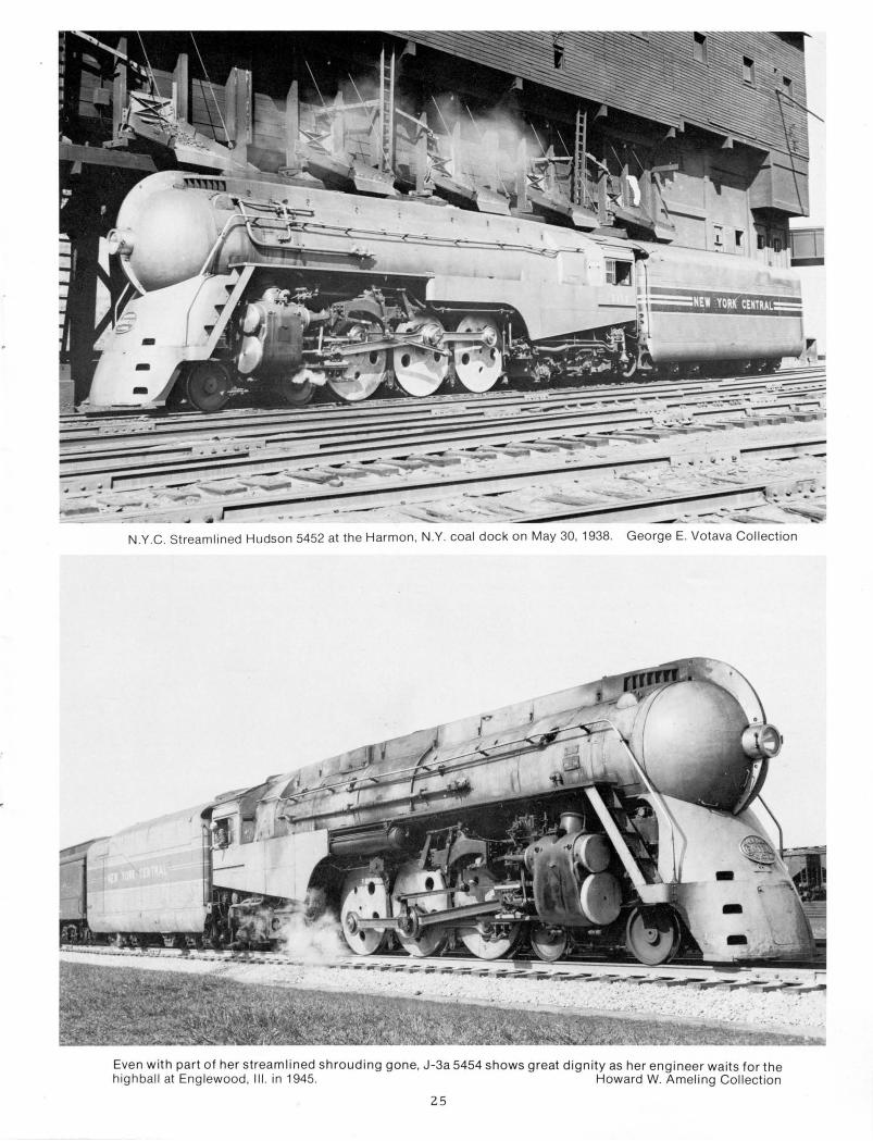
N.Y.C. Streamlined Hudson 5452 at the Harmon. N.Y. coal dock on May 30, 1938. George E. Votava Collection
Even with part of her streamlined shrouding gone, J-3a 5454 shows great dignity as her engineer waits for the highball at Englewood, Ill. in 1945. Howard W. Ameling Collection
25
- )
J-3a 5429 with the brand new ''Empire State Express" in December, 1941 .
J-3a 5429 as streamlined for the 1941 "Empire State Express"
26
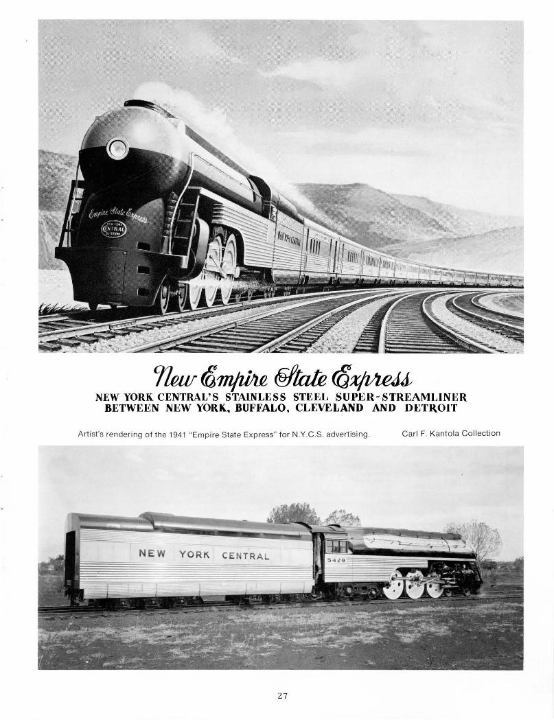
7ku f8mjzl!l£ @/Ink (Qxjl!te.U NEW YORK CENTRAL'S STAINLESS STEEL SUPER-- STREAMLINER
BETWEEN NEW YORK, BUFFALO, CLEVELAND AND DETROIT
Artist's rendering of the 1941 " Empire State Express" for N.Y .C.S. advertising . Carl F. Kantola Collection
27
WATER - 15000 GALS. COAL- 16TON5
ENGINE DESIGNED FOR 18°- 30' CURVE
~--~====~--~------------r=~~~
STEAM PRESSURE. ..... .. ........... . 21 0 lbs. KIND OF MAIN VALVE ............ . I4 in. ~istor) FIREBOX, LENGTH INSIDE .......... .... 108VS in. FIREBOX, WIDTH INSIDE ... ..• .. .... . ... 90Y4 in. GRATE AREA ................. . ..... 67.8 ~? · ft. TUBES, NUMBER LARGE ............... 45 -~ 1n . TUBES, NUMBER SMALL . ............. 190 '2\a in . TUBES, LENGTH OVER SHEETS . ..... 21 ft . 0 in . HEATING SURFACE, TUBES . ...•.. . .• 3695 sq. ft . HEATING SURFACE, FIREBOX &


![USTA TrafficAnalysisBriefing V7 0 20150530 FINAL[1] · PDF file1."Executive"Summary" ... In2014thethreemajorGulfcarriers" –"Emirates,"Qatar"Airways"and"Etihad" Airways"–"carried"some"4.3"million"passengers"intoandout"of"the](https://static.documents.pub/doc/80x56/5aa125967f8b9a46238b5bf2/usta-trafficanalysisbriefing-v7-0-20150530-final1-in2014thethreemajorgulfcarriers.jpg)


