NEWS & VIEWS VOLUME 32 2012 WWW.STRUCTINT.COM 877-4SI-POWER IMPLEMENTING A HIGH ENERGY PIPING PROGRAM pg.13 SEISMIC II/I ANALYSIS OF SBLC SYSTEM TEST TANK pg.11 ADVANCED NDE TECHNIQUES pg.6 and Their Deployment on High Pressure Equipment Wind Turbine Inspection pg. 21
Transcript
NEWS & VIEWS
VOLUME 322012
WWW.STRUCTINT.COM
8 7 7 - 4 S I - P O W E R
IMPLEMENTING A HIGH ENERGYPIPING PROGRAM pg.13
SEISMIC II/I ANALYSIS OFSBLC SYSTEM TEST TANK pg.11
ADVANCED NDE TECHNIQUES pg.6and Their Deployment on High Pressure Equipment
WindTurbine Inspection
pg. 21
8 7 7 - 4 S I - P O W E R2 PRESIDENT’S CORNER 8 7 7 - 4 S I - P O W E R
A s I sit here to write my column for this issue of News &Views, I have one thought stuck in my head – there is no current overarching issue affecting the electric utility and energy markets right now. It feels like a time of calm or stability in the market, yet many things can affect the industry calm, and I know it’s only a matter of time until the next “thing” happens.
Thankfully, there have been no recent natural disasters, economic plunges, unforeseen regulatory actions, national emergencies or major equipment failures – not only for the victims of such events – but also for the continued relative stability of the energy market. Of course, this relative stability is still largely driven by uncertainty, so it’s far from ideal. Therefore, as we continue to do our jobs we must always be prepared to respond to the inevitable disruption of the calm. Whether that disruption comes from a natural disaster, emergent technical issue, policy change resulting from the forth- coming elections, or a myriad of other events we know we need to keep the lights on and homes heated. Not only do we need to keep the lights on, we must do so while ensuring plants, systems, and components are safe, serviceable, reliable, and in regulatory compliance. Even in calm times, aging continues.
At Structural Integrity (SI), we seek to continuously create and deploy innovative solutions that are of value to our customers. In some cases, this involves upgrading current tools, technologies, and practices we have used for years. Many companies may not invest in ‘mature offerings or technologies’ but we are never satisfied if improvements can be made that make it easier and safer to keep the lights on. Examples include:
■ High Energy Piping (HEP) girth and longitudinal seam weld assessments using ultrasonic array probe and instrument technology was developed and qualified for use by Structural Integrity during the early 1990’s. Since that time, we have successfully migrated this technique to more advanced phased array platforms developed and released between 2000 and 2005. More recently, we completed yet another validated migration of this assessment technology onto the latest phased array technology available. The advancements provided in this newest technology provide more advanced and complex phased array controls, improved data acquisition rates, and analysis routines, including 3-D data simulation.
■ While we have been assisting clients with FatiguePro for over 20 years, we are currently completing development of a new version, SI:FatiguePro 4. This new fatigue monitoring software, available to utilities for deployment later this year, is being revamped to include more detailed stress calculations. This will address an NRC concern about simplified analysis, as well as automatically calculate fatigue usage factors, including the effect of reactor water environment. (See SI: FatiguePro 4.0, page 28)
■ We have provided boiler tube lifing for over 20 years, always with the understanding that limitations associated with the number of assumptions built into the time/temperature/oxide thickness correlations would limit applicability of the lifing calculations to
WWW.STRUCTINT.COM PRESIDENT’S CORNER 3
only the specific test location. To remove some of the uncertainty associated with this deterministic method, we recently completed a probabilistic gas touched length analysis tool which provides predictions of tube failure probability for entire superheater or reheater sections, rather than just at the location of oxide and wall thickness measurements. This probabilistic method, which is underpinned by the basic science of oxide growth, tube metal temperature calculations and creep lifetime prediction, facilitates risk-based assessment of the many miles of tubing in boilers and provides estimates of future failure rates for high-temperature tubing sections.
Similarly, there are new solutions for more recent emergent issues that benefit from continued development and optimization. Some of these that we are more fully developing include:
■ The assessment and life management of Creep Strength Enhanced Ferritic (CSEF) material has been a major concern for the fossil market and specifically for heat recovery steam generator’s (HRSG’s). Our industry-leading approach integrates our V91 risk-based method with stress analysis and quantitative life predictions provide our clients with an updatable tool for planning inspections and repairs. We advocate assessment protocols, repair practices and manufacturing recommendations based on internal research and knowledge gained through collaboration with EPRI and other international institutions. We encourage and assist users of CSEF materials to develop proper specifications and then tightly adhere to those specifications throughout all phases of manufacturing and field construction.
■ ASME Code-compliant ultrasonic examinations (aka UT in lieu of RT) are growing in popularity as welding contractors and utility personnel recognize the improved production rates and reduced safety risks associated with the use of radiographic isotope sources. Although we have conducted several thousand boiler tube butt weld acceptance examinations, it is only recently that advanced phased array UT in lieu of RT has become more accepted. In response to industry requests, we have developed and qualified numerous Code-compliant PAUT procedures for both the fossil and nuclear power generation industries. Further developments are being made to improve the discriminating accuracy of these techniques to ensure that acceptable fabrication defects aren’t overstated in their length and through wall dimensions.
Lastly, the engineers at Structural Integrity not only look for ways to keep the lights on today, but also what will be needed to keep them on in the future. Therefore, through constant market awareness and participation in numerous industry forums (EPRI, ASME, AWS, etc.), we place an importance on developing the solutions today for the emergent issues of tomorrow. Just a few that we are currently working on include:
■ While we may be best known for our inspection, evaluation, and assessment of any critical component made of metal, there are critical steel-reinforced concrete structures with similar aging issues and programmatic assessment needs. A few that immediately come to mind are reactor containment buildings, hyperbolic cooling towers, and turbine pedestals. Therefore, Structural Integrity, in partnership with other key consulting providers, is developing the necessary programs and tools to properly manage these critical aging components.
■ Advancements in guided wave technologies (GWT) have opened up the potential for screening boiler tubes for damage mechanisms that could result in through wall failures. Specific applications considered most appropriate for GWT are areas of restricted and/or limited accessibility. However, the complexity of most conventional boilers and heat recovery steam generators (HRSG) presents extensive challenges that limit the effectiveness of GWT as currently applied for pipe systems. We, and our alliance partner FBS, Inc., have completed preliminary studies validating the detection of various failure mechanisms. We will continue to evaluate the challenges that limit the use of GWT for more effectively screening boiler and HRSG tubing.
■ New regulation passed in January 2012 is driving gas transmission pipeline operators to ensure that verifiable, traceable, and complete records exist (and have been reviewed) in determining the Maximum Allowable Operating Pressure (MAOP). We are working with one of our partner firms to develop a comprehensive program and supporting analytical tools for the collection, organization and review of these records as well as prioritization schemes and action plans for incomplete or missing records.
Again, at Structural Integrity, we know the period of calm is only temporary. We enjoy it while we can, but we also never stop our efforts to keep the lights on.
8 7 7 - 4 S I - P O W E R4 CONTENTS
CONTENTS VOLUME NUMBER 32
8 7 7 - 4 S I - P O W E R
06 Advanced NDE Techniques and Their Deployment on High- Pressure Equipment ■
By: JEFF MILLIGAN, DAN PETERS and JASON VAN VELSOR
11 Seismic II/I Analysisof SBLC System Test Tank ■
By: SHARI DAY and MOSES TAYLOR
13 Structural Integrity Awarded Contract By Fortune 250 Energy CompanyAssists with the Implementation of their High Energy Piping Program ■By: MATTHEW DOWLING
14 Postulating High EnergyLine Break LocationsAn Improved Technical Basis and Suggested Approach ■By: TERRY HERRMANN
17 USA/STARS Preferred VendorPreferred Vendor for Guided Wave Testing Services ■By: ROGER ROYER
Compared to conventional single-coil eddy current technology, eddy current array technology drastically reduces inspection time because a large area can be scanned in a single probe pass while maintaining high resolution. ECA also reduces the complexity of mechanical and robotic scanning systems required to inspect a specific surface geometry or surface area. When used with an encoded scanning system, it provides real-time
Many advances in Non-Destructive Examination (NDE) have occurred in recent years. Some of these are becoming common in typical industry applications and are slowly migrating their way into niche industries, such as high-pressure applications. These advanced NDE techniques include the use of Linear Phased Array (LPA) ultrasonic examination for volumetric examination and Eddy Current Array (ECA) technology for surface examination. Advancements in ultrasonic Guided Wave Testing (GWT) also show promise for specific applications involving long tubes, such as in tubular LDPE reactors.
Complete periodic assessment of a high pressure vessel’s condition is key to safe, long-term reliable operation. Structural Integrity provides a comprehensive inspection program that analyzes high pressure equipment and identifies critical areas where a potential failure mode may exist. Using advanced NDE techniques, we are able to overcome some common challenges found in high-pressure equipment, like access issues of small diameter deep bores, large and thick section components, weld overlays and examination of thick section welds, complex geometries, and the requirement to detect small crack sizes due to equipment design and materials used. ADVANCED NDE APPROACHESMany traditional NDE methods, such as liquid penetrant testing (PT), magnetic particle testing (MT), eddy current testing (ET), radiographic testing (RT) and conventional single-element ultrasonic testing (UT) can be replaced or improved by using an advanced NDE approach.
EDDY CURRENT ARRAY (ECA)The eddy current array inspection approach provides a surface, or near-surface, inspection of electrically conductive materials, such as stainless steel, and is therefore well suited for inspection of many high-pressure equipment materials. ECA provides many advantages over other surface NDE techniques such as PT and MT. Some of these advantages include increased speed of inspection, digital data storage for a permanent record, depth sizing, no chemical waste, and ECA can be done remotely using an automated scanner.
Eddy current inspection is an NDE method that utilizes the principle of electromagnetism, specifically electromagnetic induction. When an alternating electric current is applied to a conductor, such as a copper wire (coil or probe), a magnetic field develops in and around the coil. When this coil is brought close to a conductive material, such as stainless steel, the coil’s changing magnetic field generates current flow in the conductive material. The induced current flows in closed loops called eddy currents. Changes in the flow of these eddy currents, like disruption by a flaw, can be detected and quantified on the eddy current instrument display.
Eddy current array technology provides the ability to electronically drive multiple eddy current coils, which are placed side by side as an array in the same probe assembly. Each individual eddy current coil in the probe produces a signal relative to the phase and amplitude of the structure below it. This data is referenced to an encoded position and time, and can be represented graphically as a C-Scan image. The ECA probe can be designed to be flat or contoured to fit a specific geometry (Figure 1). Some probes are sold as flexible arrays that can fit multiple contours. The size, frequency, and amount of coils in the array probe will be dependent on inspection requirements
Figure 1. a) Flat ECA probe; b) Radiused ECA probe
like material type, critical flaw size, and part geometry. The capability of the eddy current array acquisition system will also dictate the amount of coils available for inspection.
ADVANCED NDE TECHNIQUES AND THEIR DEPLOYMENT ON HIGH PRESSURE EQUIPMENT 7WWW.STRUCTINT.COM
Figure 2. ECA C-Scan, Impedance Plane (Lissajous), and strip chart display of a reference standard with different size EDM notches
C-Scan image of the inspected region. This facilitates data interpretation, and improves flaw detection, sizing, and probability of detection.1 Encoded eddy current array technology also allows for a permanent record of inspection data that can be referred to for future inspections.
Typical for flaw detection, a reference standard calibration block is needed in order to normalize the individual coils of the eddy current array probe and setup a comparison of known flaw sizes. Figure 2 shows an ECA C-Scan display next to the impedance plane display, or Lissajous, and under that is a strip chart display. An image of a radiused reference standard can also be seen in Figure 2. The C-Scan display shows a top down view of the encoded scan area with colors representing signal amplitude in volts. Further analysis of any position on the C-Scan display can be done using the impedance plane (Lissajous) or strip chart displays. Signals from individual
coils can be analyzed to
determine accurate measurements of voltage amplitude and phase angle in order to categorize and quantitatively size indications.
LINEAR PHASED ARRAY (LPA) ULTRASONICSThe linear phased array inspection approach provides a volumetric inspection of materials and is therefore well suited for inspection of potential cracking on many high-pressure components. LPA ultrasonic technology utilizes an array transducer (probe) that contains multiple transducer elements, as opposed to the single element of conventional pulse-echo transducers. Each element of an array probe can be utilized as a transmitter and/or receiver, and when each transducer element is pulsed sequentially with small, precise timing delays imposed one to the next, ultrasonic beam steering and focusing can be varied and controlled. A linear array consists of a number of linear elements arranged in a single row, or in a two-dimensional pattern. Array probes are available in a variety of shapes, sizes, number of elements and frequencies.
All these parameters are important in determining the steering and focusing capabilities of the probe.2
Linear phased array technology provides the ability, by proper phasing, to steer the ultrasonic beam
t h r o u g h a series of different a n g l e s covering a sector typically over a range of 60º, depending on wave mode and array parameters. The linear array is used primarily to influence beam direction, electronically focus the beam, or a combination of the two. A true spatial representation of the linear array data requires that the data be presented in polar coordinates. The amplitudes of the waveforms, plotted sequentially at each digitization point along each waveform, are typically presented in colors so the presentation provides instant recognition of the position of a reflector as well as its significance in terms of reflection amplitude. These plots have become known as sectorial scans, or S-scans, because they represent sectors of the cross-section of the component in the plane of the beam.
Continued on next page
Figure 3. 5L32 probe beam simulation at 40º in carbon steel
One advantage of linear phased array technology includes inspection of small indications over long metal sound paths. A feasibility study was performed using a 32 element, 5 MHz linear array probe (commonly referred to as 5L32), which allowed for focusing of the ultrasonic sound beam to over 9.5 inches deep (12.4 inch sound path distance) in a low-alloy carbon steel mock-up block. Figure 3 shows a beam simulation of this 5L32 transducer at a 40º refracted shear wave
angle. As can be seen, the greatest amount of sound energy is focused near 6.5 inches deep in the
part, however the -6dB focal zone stretches to over 9.5 inches deep. This focusing capability allows for
excellent sensitivity and detection of a 0.04 inch wire EDM notch located 8.25 inches deep in the mock-up block. The focusing capability of the 5L32 also provides clear detection from a 0.04 inch wire EDM notch that is at a depth of 12.75 inches (18.0 inch sound path) from the probe inspection position, as seen in Figure 4.
An advantage of using these advanced NDE techniques is the ability to successfully detect and size small flaws in areas where traditional NDE techniques would be limited. One example of this would be the inspection of threads in pressure vessel closures. Figure 5 is an example of a buttress thread setup, similar to what may be used in a vessel closure. Traditional methods for crack detection at the thread roots would commonly be a surface exam using either PT or MT. These methods typically work well, but they offer no depth sizing information. The flaw depth sizing advantage of LPA can be observed in Figure 5. Artificial defects are shown to be easily detected and sized between 0.010 inch and 0.020 inch deep in expected cracking locations.
GUIDED WAVE TESTING (GWT)Long-range guided wave testing of piping has been successfully used in the energy industry for over 10 years to inspect long lengths of piping for corrosion and other damage. Considered a screening technology, guided waves are capable of detecting changes in acoustic impedance, which is affected by variations in local material properties, changes in stiffness, and by changes in the cross-sectional area (CSA) of the pipe. When inspecting for corrosion or circumferential cracking, variations in CSA are the primary cause of indications.
The primary advantage of GWT is its ability to inspect long sections of pipe from a single sensing position. Ultrasonic guided waves utilize lower frequency activation to generate waves that are guided by the boundary of the structure and capable of traveling great distances.3 Figure 6 shows a still-frame from a finite-element model showing the propagation of a guided wave down the length of a pipe. Other advantages include 100% volumetric coverage of the inspected length, the ability to inspect inaccessible piping, and axial and circumferential location and extent classification capabilities.
Guided wave testing has much potential for the inspection of tubular high-pressure polyethylene reactors with external cooling jackets. Because the cooling jackets prevent access to
8 ADVANCED NDE TECHNIQUES AND THEIR DEPLOYMENT ON HIGH PRESSURE EQUIPMENT 8 7 7 - 4 S I - P O W E R
Figure 4: S-scan (35º-55º refracted shear wave beam angles) of 0.04 inch wire EDM notch, 12.75 inches deep (18.0 inch
sound path at 45º) in carbon steel
0.04 in Wire EDM (subsurface)
a majority of the tube surface, traditional NDE methods cannot be used on these thick-walled components. As a result, they are generally allowed to run until they fail. With GWT, the entire tube can be screened for corrosion or circumferential/oblique cracking using a transducer collar placed on the end of the tube, prior to the start of the cooling jacket. An example of the GWT of a thick-walled (~2 in.) pipe is shown in Figure 7. From the data ,it is seen that welds and supports are clearly identified over a test length of more than 130ft. The signal-to-noise ratio (SNR) of the scan is excellent, demonstrating the potential for the inspection of other thick-walled components, such as polyethylene reactors.
COMPUTERIZED DATA ACQUISITION AND SCANNERS
ADVANCED NDE TECHNIQUES AND THEIR DEPLOYMENT ON HIGH PRESSURE EQUIPMENT 9WWW.STRUCTINT.COM
Figure 5: LPA Ultrasonic Images of Buttress Thread EDM notches
A major advantage of the advanced NDE techniques are the computerized data acquisition and data storage capabilities. NDE inspections are highly reproducible when inspecting with automated (moved by encoded motor-controlled drive unit) or semi-automated (encoded movement by hand) scanning systems. Encoded scanning systems offer speed and versatility when inspecting large areas, as well as precise movement and adjustment of data collection resolution when dealing with complex geometries. Having a digital permanent record can provide baseline inspection data, and assist in monitoring discontinuities over successive inspection intervals. This permanent, digital inspection data can help calculate growth rates of discontinuities and plan repair or replacement activities. Accurate NDE inspection data is an important tool for implementing Risk Based Inspection Programs, Fitness for Service Analysis EDM Notch
Angular Sweep from -30˚ to 30˚
0.010 in. notch
0.020 in. notch
Figure 6: Still-frame from a finite-element animation showing an ultrasonic guided wave propagating down a length of a pipe.
Propagation Direction
Continued on next page
Figure 7: Long-range guided wave scan of a ~2” thick steel pipe showing clear indications from welds and supports (as illustrated
in the diagram above the scan) for over 130ft of piping
10 8 7 7 - 4 S I - P O W E R10 ADVANCED NDE TECHNIQUES AND THEIR DEPLOYMENT ON HIGH PRESSURE EQUIPMENT 8 7 7 - 4 S I - P O W E R
and remaining useful life programs. Additionally, sophisticated data analysis software can be used to assist in flaw sizing and interpretation, and in some cases 3-D image presentation of defects.
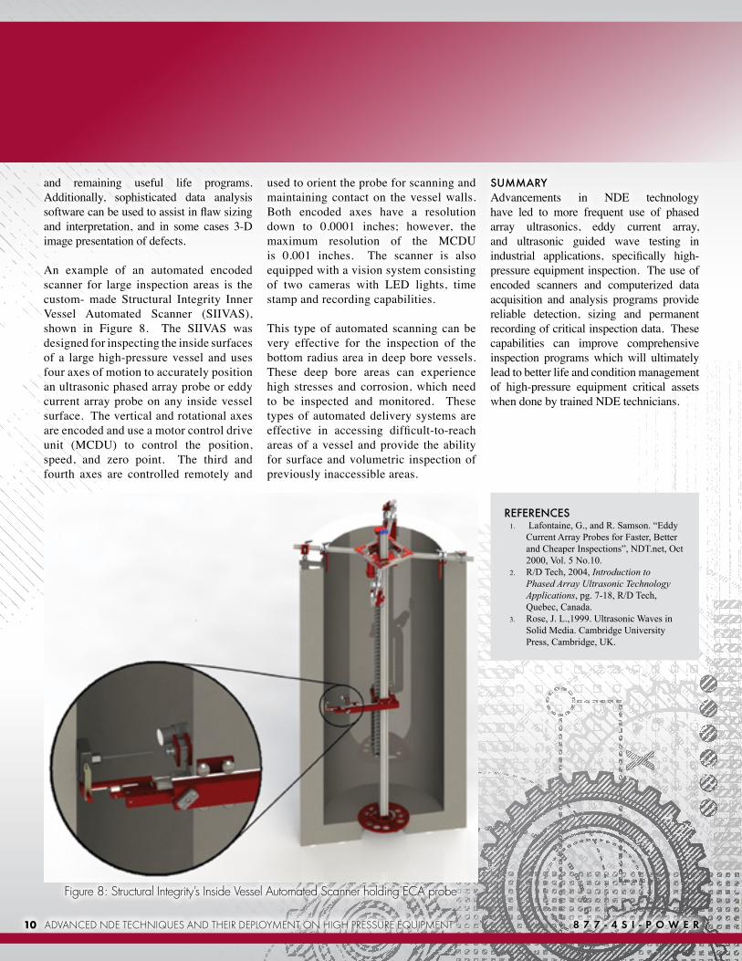
An example of an automated encoded scanner for large inspection areas is the custom- made Structural Integrity Inner Vessel Automated Scanner (SIIVAS), shown in Figure 8. The SIIVAS was designed for inspecting the inside surfaces of a large high-pressure vessel and uses four axes of motion to accurately position an ultrasonic phased array probe or eddy current array probe on any inside vessel surface. The vertical and rotational axes are encoded and use a motor control drive unit (MCDU) to control the position, speed, and zero point. The third and fourth axes are controlled remotely and
REFERENCES1. Lafontaine, G., and R. Samson. “Eddy
Current Array Probes for Faster, Better and Cheaper Inspections”, NDT.net, Oct 2000, Vol. 5 No.10.
used to orient the probe for scanning and maintaining contact on the vessel walls. Both encoded axes have a resolution down to 0.0001 inches; however, the maximum resolution of the MCDU is 0.001 inches. The scanner is also equipped with a vision system consisting of two cameras with LED lights, time stamp and recording capabilities.
This type of automated scanning can be very effective for the inspection of the bottom radius area in deep bore vessels. These deep bore areas can experience high stresses and corrosion, which need to be inspected and monitored. These types of automated delivery systems are effective in accessing difficult-to-reach areas of a vessel and provide the ability for surface and volumetric inspection of previously inaccessible areas.
SUMMARYAdvancements in NDE technology have led to more frequent use of phased array ultrasonics, eddy current array, and ultrasonic guided wave testing in industrial applications, specifically high-pressure equipment inspection. The use of encoded scanners and computerized data acquisition and analysis programs provide reliable detection, sizing and permanent recording of critical inspection data. These capabilities can improve comprehensive inspection programs which will ultimately lead to better life and condition management of high-pressure equipment critical assets when done by trained NDE technicians.
Structural Integrity recently completed calculations in support of the seismic qualification of a standby liquid control (SBLC) system test tank, which originally had not been designed considering seismic loads. The SBLC system is a backup system that can be used for nuclear reactor shutdown from full power in the event that the control rods cannot be inserted. The system carries a liquid control chemical (boron, in solution) and consists of a large storage tank, pumps, valves, piping and a small test tank, which is used periodically during testing. The test tank is classified as non-safety related but is located near safety related components and equipment. A seismic II/I evaluation was required to ensure that the test tank, if filled with water, would not collapse and damage safety-related components during a design basis earthquake (DBE).
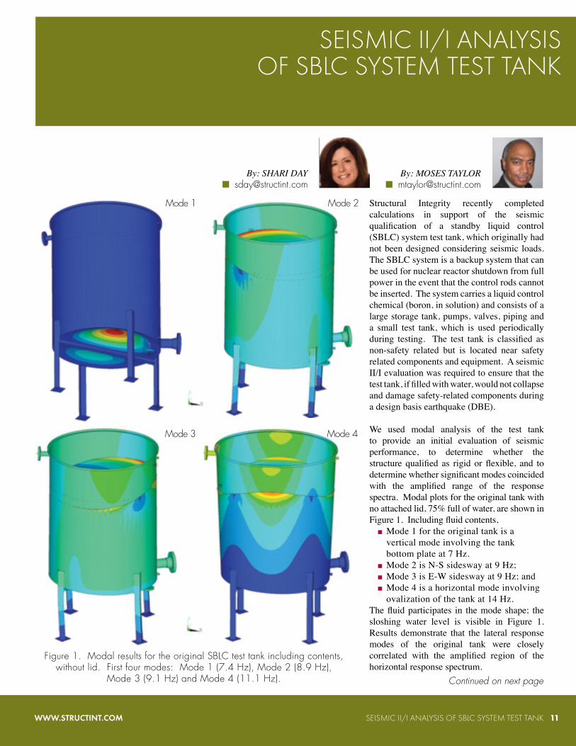
We used modal analysis of the test tank to provide an initial evaluation of seismic performance, to determine whether the structure qualified as rigid or flexible, and to determine whether significant modes coincided with the amplified range of the response spectra. Modal plots for the original tank with no attached lid, 75% full of water, are shown in Figure 1. Including fluid contents,
■ Mode 1 for the original tank is a vertical mode involving the tank bottom plate at 7 Hz.
■ Mode 2 is N-S sidesway at 9 Hz; ■ Mode 3 is E-W sidesway at 9 Hz; and ■ Mode 4 is a horizontal mode involving ovalization of the tank at 14 Hz.
The fluid participates in the mode shape; the sloshing water level is visible in Figure 1. Results demonstrate that the lateral response modes of the original tank were closely correlated with the amplified region of the horizontal response spectrum.
SEISMIC II/I ANALYSISOF SBLC SYSTEM TEST TANK
WWW.STRUCTINT.COM SEISMIC II/I ANALYSIS OF SBLC SYSTEM TEST TANK 11
Figure 1. Modal results for the original SBLC test tank including contents, without lid. First four modes: Mode 1 (7.4 Hz), Mode 2 (8.9 Hz),
Mode 3 (9.1 Hz) and Mode 4 (11.1 Hz). Continued on next page
Mode 1
Mode 4Mode 3
Mode 2
8 7 7 - 4 S I - P O W E R
Figure 2. Modal results for final retrofit of the SBLC test tank. Mode 9 (top), 28.2 Hz; Mode 10, 29.3 Hz.
Figure 3. Results of final load combination series with all loads
superimposed. Principal stress contours, controlling load combination
12 SEISMIC II/I ANALYSIS OF SBLC SYSTEM TEST TANK
The existing design basis calculations for the test tank only included seismic evaluation of the anchor bolts. After an initial evaluation and modal analysis showed that the test tank legs were not adequate under DBE conditions when the test tank was filled with water, the station designed a retrofit for the tank that included bracing for the legs and supplementary support for the tank bottom. We used the finite element model of the tank developed for the seismic qualification to evaluate retrofit options as well as to establish adequacy of the final tank support configuration.
Modal analysis of the retrofitted tank, Figure 2, demonstrates the benefit of adding lateral support. The cross-bracing effectively minimizes tank sidesway modes and removes tank sidesway from the flexible range of the seismic response spectrum. With the legs braced, tank lateral modes occur at 28 Hz and 29 Hz, close to the rigid response region of the horizontal response spectrum.
Next, we evaluated the test tank for seismic load combinations by the response spectrum method, with superimposed seismic and dynamic loads imposed by attached piping. The nozzle loads applied in the piping load cases were generated by the station using component stiffnesses obtained from our finite element model at the nozzle locations. Stress results for the tank are shown in Figure 3 for the controlling load combination. Stresses were found to be low except at the tank bottom plate. Further nonlinear elastic-plastic analysis of the tank, including stress stiffening, showed that the bottom plate would remain intact during the loading event, with stresses by elastic-plastic analysis no higher than 35 ksi.
WWW.STRUCTINT.COM
STRUCTURAL INTEGRITY AWARDED CONTRACT BY FORTUNE 250 ENERGY COMPANY
Structural Integrity has joined forces with a leading energy provider to assist with the implementation of their fleet wide High Energy Piping Management Program. This program will be specifically designed to meet their corporate goals.
As the power plant fleet in the US continues to age, the possibility of failure in a high energy piping system increases. Plant owners are facing significant challenges associated with developing and implementing effective programs to help manage these critical assets. Shrinking budgets, loss of highly experienced staff and increasing harsh operational modes put additional pressure on those tasked with managing these programs. In addition, many utilities have acquired plants that may have some form of existing program. These plants are often in very different geographic locations.
In order to effectively meet these significant challenges, a centralized, consistent and coordinated program should be established. Limited resources require that plants, systems and individual welds must be prioritized. To help meet this challenge, Structural Integrity has developed the Vindex methodology.
To ensure that management’s requirements are being met for High Energy Piping, we developed a risk-based prioritization method that rank-orders steam piping welds with regard to their vulnerability to service-related damage along with the consequences of potential failures resulting from this damage. The resulting vulnerability index (Vindex) allows us to target limited resources to the largest risk contributors within a given piping system or generating unit, or across the entire fleet of generating units within a given utility’s system. Application of Vindex to multiple piping systems allows for systematic and consistent risk assessment of the critical high energy piping system welds within the fleet.
The highest risk contributing components in the diminishing risk plot show the largest contribution to cumulative risk. Note in the plot that of the 55 components, 17 are responsible for 50% of the cumulative risk. The Pareto 80/20 rule (i.e., 20% of the components cause 80% of the problems) is utilized to approximate how a few components contribute to a large portion of the risk. This diminishing risk plot more accurately depicts this relationship based on the specific risk characteristics of the system being assessed. This plot is a good description to management of the amount of risk addressed by proceeding with the next level of the risk assessment process. We are currently in process of implementing this across their fleet.
Assists with the Implementationof their High Energy
Piping Program
Rank-Order ID
800000
700000
600000
500000
400000
300000
900000
200000
100000
0200150100500 250
Diminishing Risk Plot(Main steam and hot reheat piping systems.)
Cum
ula
tive
Ris
k
Highest Risk Contributing Components
STRUCTURAL INTEGRITY AWARDED CONTRACT BY FORTUNE 250 ENERGY COMPANY 13
With existing plants seeking to renew their operating licenses for an additional 20 years after the original 40-year license term -- and new plants being designed for a 60-year period -- the current fatigue usage criterion used to postulate High-Energy Line Break (HELB) locations could increase the number of locations where reactor coolant piping breaks need to be addressed.
This can result in: ■ costly analysis and ■ the addition of pipe break protection hardware without a commensurate safety benefit.
This concern was the basis for application of the Leak Before Break, (LBB) approach implemented in the 1ate 1980’s. Currently, for plants with piping systems designed to ASME Section III, a cumulative usage factor (CUF) of 0.1 is one of the criteria for postulating break locations in reactor coolant pressure boundary piping1. The CUF criterion has gone unchanged since the early 1970s. The basis for using CUF is that thermal fatigue is a damage mechanism known to cause through-wall leaks in piping systems. There is no specific technical basis for the value of 0.1 used in the existing regulatory guidance.
Structural Integrity (SI) recently prepared an EPRI technical report titled “Improved Basis and Requirements for Break Location Postulation2,” which reviewed industry experience, evaluated the relationship between fatigue usage, leak probability and risk, and provided a suggested approach for future regulation. This report is now publicly available from EPRI at no charge at http://my.epri.com/portal/server.pt?Abstract_id=000000000001022873.
Since the 0.1 CUF criterion was issued, a significant amount of industry experience has demonstrated that fatigue is less likely to result in high- energy piping failure than several other mechanisms. Various studies were reviewed, covering more than 9,000 reactor years of operation worldwide over a 35 year time span3. This review found that more than 95% of piping cracks, leaks and ruptures were due to mechanisms other than thermal fatigue, as shown in the graphic to the left.
An Improved Technical Basis and Suggested Approach
Vibration Fatigue (total), 53%
FAC, 21%
Cavitation-Erosion, 3%IGSCC, 9%
TGSCC, 8%
PWSCC, 2%
Thermal Fatigue, 4%
Contribution to Reported Piping Failures (EPRI 1022873; obtained from NUREG/CR-6936)
14 POSTULATING HIGH ENERGY LINE BREAK LOCATIONS 8 7 7 - 4 S I - P O W E R
POSTULATING HIGH ENERGY LINE BREAK LOCATIONS 15WWW.STRUCTINT.COM
POSTULATING HIGH ENERGY LINE BREAK (HELB) LOCATIONS
This is due to multiple factors, which include the stress profile (membrane, bending, radial gradient thermal), geometry and use of stress indices, material, temperature, crack growth relationships and others. Due to these factors and, since the ASME design curves do not follow a line of constant crack initiation probability as shown in the plot above, meaningful conclusions regarding differences between a CUF of 0.1 and a CUF of 0.4, for example, cannot be reached.
Stre
ss A
mpl
itude
(ks
i)
1010 102 106105103103 107
2X10²
102
10
20
50
Cycles
P=.00001P=.00010
P=.00100P=.01000
P=.10000P=.50000
ASME CURVE
The majority of the thermal fatigue-related failures were due to generic issues not evaluated during original design, and which have subsequently been addressed through regulatory action, including:
■ BWR feedwater and CRD nozzle cracking (NUREG-0619). ■ Feedwater piping cracking in PWRs (Bulletin 79-13). ■ Leakage at valves (Bulletin 88-08). ■ Thermal stratification (Bulletin 88-11). ■ Reactor water environmental effects on fatigue (NUREG/CR-69097 and other documents identified in the current revision of NUREG-18014)
One of the challenges with providing a technical basis for a specific CUF value is that CUF can be calculated using more than one technical approach allowed by the ASME Code (e.g., NB-3600 vs. NB-3200). To more fully understand the relationship between thermal fatigue and failure of piping systems, we chose to pursue a risk-informed approach, which would be consistent with the NRCs Risk-Informed and Performance-Based Plan (RPP) initiative5.
Previously, the NRC commissioned work to investigate the risk impact of an extended operating period of 20 years on existing plants6. This study evaluated a range of fatigue-sensitive locations for each plant design as well as newer and older vintage plants. We applied the same approach with an updated ASME fatigue curve, NUREG/CR-69097 strain life relationships and a 0.1% fractile curve.
Five representative components were selected from NUREG/CR-66746, considering material type, cumulative usage and environment. The pc-PRAISE8 code , developed by SI’s Dr. David Harris and Dilip Dedhia, was used to calculate leak probabilities vs. operating time using the cyclic stresses and environments from NUREG/CR-66746. CUFen (CUF including environmental effects) values were then calculated using the updated ASME fatigue curve. Core damage frequency (CDF) was estimated using the relationships for the probability of core damage given pipe rupture that were developed in NUREG/CR-66746, which can vary by several orders of magnitude for various components and locations. The values of CDF were then compared to the EPRI PSA Applications Guide9 criteria, which is used by the NRC in Regulatory Guide 1.17410.
As can be seen in the plot to the right, the lack of a direct correlation between Core Damage Frequency and component CUFen values compromises efforts to use specific values of CUFen as a criterion for postulating HELB locations.
CE new surge line nozzle
W new charging nozzle
CE old charging nozzle
GE new RHR straight pipeW old RPV nozzle
1.81.61.41.210.80.60.40.20 2
10-6
10-7
10-8
10-9
10-10
10-11
10-12
10-13
10-5
CD
F
CUFenRelationship between CDF vs. CU sub Fen for Components Evaluated
(EPRI 1022873)Continued on next page
16 POSTULATING HIGH ENERGY LINE BREAK LOCATIONS 8 7 7 - 4 S I - P O W E R
Region I
Region III
Region II
Region I● NO Changes Allowed
Region II● Small Changes● Track Cumulative Impacts
Region III● Very Small Changes● More Flexibility with Respect to Baseline CDF● Track Cumulative Impacts
∆ C
DF
10-5
10-6
10-5 10-4 ∆ CDF
And, as mentioned previously, the probability of CDF given leakage varies for different components. So even if there was a good correlation between leak probability and CUFen, agreement would be eliminated by component-specific relationships between the probability of leakage and CDF.
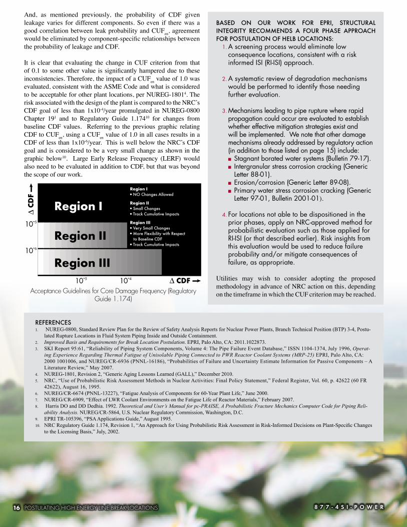
It is clear that evaluating the change in CUF criterion from that of 0.1 to some other value is significantly hampered due to these inconsistencies. Therefore, the impact of a CUFen value of 1.0 was evaluated, consistent with the ASME Code and what is considered to be acceptable for other plant locations, per NUREG-18014. The risk associated with the design of the plant is compared to the NRC’s CDF goal of less than 1x10⁻⁴/year promulgated in NUREG-0800 Chapter 191 and to Regulatory Guide 1.17410 for changes from baseline CDF values. Referring to the previous graphic relating CDF to CUFen, using a CUFen value of 1.0 in all cases results in a CDF of less than 1x10⁻⁶/year. This is well below the NRC’s CDF goal and is considered to be a very small change as shown in the graphic below10. Large Early Release Frequency (LERF) would also need to be evaluated in addition to CDF, but that was beyond the scope of our work.
REFERENCES 1. NUREG-0800, Standard Review Plan for the Review of Safety Analysis Reports for Nuclear Power Plants, Branch Technical Position (BTP) 3-4, Postu-
lated Rupture Locations in Fluid System Piping Inside and Outside Containment.2. Improved Basis and Requirements for Break Location Postulation. EPRI, Palo Alto, CA: 2011.1022873.3. SKI Report 95:61, “Reliability of Piping System Components, Volume 4: The Pipe Failure Event Database,” ISSN 1104-1374, July 1996, Operat-
ing Experience Regarding Thermal Fatigue of Unisolable Piping Connected to PWR Reactor Coolant Systems (MRP-25) EPRI, Palo Alto, CA: 2000 1001006, and NUREG/CR-6936 (PNNL-16186), “Probabilities of Failure and Uncertainty Estimate Information for Passive Components – A Literature Review,” May 2007.
4. NUREG-1801, Revision 2, “Generic Aging Lessons Learned (GALL),” December 2010.5. NRC, “Use of Probabilistic Risk Assessment Methods in Nuclear Activities: Final Policy Statement,” Federal Register, Vol. 60, p. 42622 (60 FR
42622), August 16, 1995.6. NUREG/CR-6674 (PNNL-13227), “Fatigue Analysis of Components for 60-Year Plant Life,” June 2000.7. NUREG/CR-6909, “Effect of LWR Coolant Environments on the Fatigue Life of Reactor Materials,” February 2007.8. Harris DO and DD Dedhia. 1992. Theoretical and User’s Manual for pc-PRAISE, A Probabilistic Fracture Mechanics Computer Code for Piping Reli-
ability Analysis. NUREG/CR-5864, U.S. Nuclear Regulatory Commission, Washington, D.C.9. EPRI TR-105396, “PSA Applications Guide,” August 1995.10. NRC Regulatory Guide 1.174, Revision 1, “An Approach for Using Probabilistic Risk Assessment in Risk-Informed Decisions on Plant-Specific Changes
to the Licensing Basis,” July, 2002.
Acceptance Guidelines for Core Damage Frequency (Regulatory Guide 1.174)
BASED ON OUR WORK FOR EPRI, STRUCTURAL INTEGRITY RECOMMENDS A FOUR PHASE APPROACH FOR POSTULATION OF HELB LOCATIONS:
1. A screening process would eliminate low consequence locations, consistent with a risk informed ISI (RI-ISI) approach.
2. A systematic review of degradation mechanisms would be performed to identify those needing further evaluation.
3. Mechanisms leading to pipe rupture where rapid propagation could occur are evaluated to establish whether effective mitigation strategies exist and will be implemented. We note that other damage mechanisms already addressed by regulatory action (in addition to those listed on page 15) include:
■ Stagnant borated water systems (Bulletin 79-17). ■ Intergranular stress corrosion cracking (Generic Letter 88-01).
■ Erosion/corrosion (Generic Letter 89-08). ■ Primary water stress corrosion cracking (Generic Letter 97-01, Bulletin 2001-01).
4. For locations not able to be dispositioned in the prior phases, apply an NRC-approved method for probabilistic evaluation such as those applied for RI-ISI (or that described earlier). Risk insights from this evaluation would be used to reduce failure probability and/or mitigate consequences of failure, as appropriate.
Utilities may wish to consider adopting the proposed methodology in advance of NRC action on this, depending on the timeframe in which the CUF criterion may be reached.
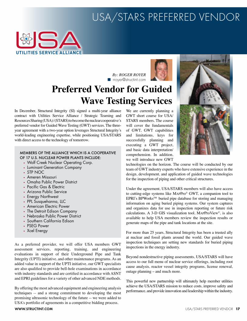
In December, Structural Integrity (SI) signed a multi-year alliance contract with Utilities Service Alliance / Strategic Teaming and Resources Sharing (USA) / (STARS) to become the nuclear cooperative’s preferred vendor for Guided Wave Testing (GWT) services. The three-year agreement with a two-year option leverages Structural Integrity’s world-leading engineering expertise, while positioning USA/STARS with direct access to the technology of tomorrow.
As a preferred provider, we will offer USA members GWT assessment services, reporting, training, and engineering evaluations in support of their Underground Pipe and Tank Integrity (UPTI) initiative, and other maintenance programs. As an added value in support of the UPTI initiative, our GWT specialists are also qualified to provide bell-hole examinations in accordance with industry standards and are certified in accordance with ASNT and EPRI guidelines for a variety of other advanced NDE methods.
By offering the most advanced equipment and engineering analysis techniques -- and a strong commitment to developing the most promising ultrasonic technology of the future -- we were added to USA’s portfolio of agreements in a competitive bidding process.
USA/STARS PREFERRED VENDOR 17WWW.STRUCTINT.COM
MEMBERS OF THE ALLIANCE WHICH IS A COOPERATIVE OF 17 U.S. NUCLEAR POWER PLANTS INCLUDE:
• Wolf Creek Nuclear Operating Corp.• Luminant Generation Company • STP NOC• Ameren Missouri• Omaha Public Power District• Pacific Gas & Electric• Arizona Public Service• Energy Northwest• PPL Susquehanna, LLC• American Electric Power• The Detroit Edison Company• Nebraska Public Power District• Southern California Edison• PSEG Power• Xcel Energy
We are currently planning a GWT short course for USA/STARS members. The course will cover the fundamentals of GWT, GWT capabilities and limitations, keys for successfully planning and executing a GWT project, and basic data interpretation/comprehension. In addition, we will introduce new GWT technologies on the horizon. The course will be conducted by our team of GWT industry experts who have extensive experience in the design, development, and application of guided wave technologies for the inspection of piping and other critical structures.
For more than 25 years, Structural Integrity has been a trusted ally at nuclear and fossil plants around the world. Our guided wave inspection techniques are setting new standards for buried piping inspections in the energy industry.
Beyond nondestructive piping assessments, USA/STARS will have access to our full menu of nuclear service offerings, including root cause analysis, reactor vessel integrity programs, license renewal, outage planning – and much more.
This powerful new partnership will ultimately help member utilities achieve the USA/STARS mission to reduce costs, improve safety and performance, and provide innovation and leadership within the industry.
18 EAF SCREENING 8 7 7 - 4 S I - P O W E R
EAF SCREENING
CHALLENGEDuring evaluation of recent license renewal applications, NRC staff has shown interest in a methodology for screening nuclear plant Class 1 systems to identify and rank bounding environmentally-assisted fatigue locations. This article presents a technical basis and possible process for screening a nuclear power plant to identify appropriate sentinel locations for systematic monitoring of the effects of environmentally-assisted fatigue (EAF) on Class 1 vessels and piping. Use of this process will assure that the most limiting locations for environmentally-assisted fatigue are identified for monitoring.
Laboratory tests have indicated that the effects of reactor coolant environment were not adequately included in the ASME Code fatigue design curves used in the original design of reactor coolant pressure boundary components. The design basis analysis for new nuclear power plants requires the application of an environmentally-assisted fatigue penalty factor (Fen). This issue has led to additional regulatory requirements for the initial license renewal, of the current operating fleet, where applicants are required to assess a limited number of locations and implement fatigue monitoring programs. There is currently no regulatory approved or common method for justifying the selected locations.
The NRC requires all license renewal applicants to assess the fatigue usage effects from a reactor water environment and demonstrate acceptable Uen (EAF Cumulative Usage Factor) for Class 1 components for the entire period of extended operation. This demonstration requires an EAF evaluation and screening of Class 1 components, some of which lack a cumulative usage factor (CUF) calculation. Evaluating Class 1 components with a CUF calculation is straightforward and may require a relatively simple evaluation process to estimate and apply environmental fatigue correction factors (Fen) to the existing CUF values. Class 1 components without CUF calculations will require a more extensive evaluation process to evaluate all locations on a similar stress basis and apply Fen factors.
EPRI REPORT PREPAREDStructural Integrity’s prepared an EPRI technical report titled “Environmentally-Assisted Fatigue Screening, Process and Technical Basis for Identifying EAF Limiting Locations.” This report provides the technical basis and process for a screening evaluation of a nuclear power plant. This screening will identify appropriate limiting
locations for systematic monitoring of the environmentally-assisted fatigue effects on Class 1 vessels and piping. Use of this process will assure that the most limiting locations for environmentally-assisted fatigue are determined on a consistent basis.
This report will be publicly available from EPRI at no charge. The process we describe represents the first step in including EAF effects in a plant’s FMP (see figure).
WHAT IS EAF SCREENING?EAF screening is the technical process of evaluating plant components with potentially high EAF behaviors to determine a ranking, and then determining appropriate sentinel components for a system or subsystem to ensure that bounding components will be tracked in a Fatigue Management Program (FMP). This process focuses engineering resources on the components that will achieve the highest EAF values first and trigger remedial actions for that and other similar components in sufficient time to continue to demonstrate acceptable fatigue management.
This screening process addresses the following elements: ■ High design CUF ■ Leading fatigue-causing transients ■ Component materials of construction ■ Ranking criteria in a system or subsystem ■ Use of bounding Fen factors for initial screening ■ Identification of dynamic loads
The desired outcome of this process is to determine plant locations that can be demonstrated to bound other locations of like materials and can serve as limiting environmentally-assisted fatigue locations for the plant.
The screening process must be applicable to both plants with and/or without an explicit fatigue design basis for all Class 1 components. For instance, older plants designed to ASME B31.1 rules for piping are not required to demonstrate a fatigue design basis denominated in cumulative fatigue usage factors (CUF), whereas newer plants designed to ASME Section III or ASME B31.7 rules are required to demonstrate that fatigue design basis. The essential difference in analysis is that the B31.1 rules for piping require evaluation of mechanical and thermal bending moment stress ranges which are compared to a pseudo-fatigue usage measure (allowable cycles vs. stress range). Analyses to B31.7 and ASME Section III rules for piping require evaluation of mechanical and thermal bending moment stresses and through-wall thermal stresses which are denominated in CUF and compared to an allowable value of 1.0.
BENEFITS FOR LICENSE RENEWAL: ■ This process will enable plant owners to demonstrate knowledge of the locations in their plant that can serve as limiting locations for environmentally-assisted fatigue evaluations.
■ This process provides the rationale for selecting these bounding locations.
■ Plant owners will minimize the necessity of formal fatigue analysis, while meeting the regulatory requirements for determining the bounding environmentally-assisted fatigue locations in the plant.
■ NRC staff can examine one possible uniform approach to determination of limiting locations for EAF evaluations for license renewal applications.
“bundled” set of plant transients and/or a mixture of bundled and unbundled transients.
• Components or locations in components evaluated to additional refined analyses (e.g., elastic-plastic analysis), while other components or locations are not.
■ To assure consistent determination of relative fatigue accumulation, these differences must be accounted for or eliminated. The screening processes are designed to make this common basis determination.
■ The screening process is used to review all Class 1 plant components susceptible to environmentally-assisted fatigue, categorize them into thermal groups, and identify one or more sentinel locations for each thermal group that can be analyzed and monitored for environmentally-assisted fatigue usage.
■ The idea of sentinel location extends the basic approach that was used in NUREG/CR-6260 of analyzing a few challenging locations to represent the entire plant, by adding a semi-quantitative ranking system to demonstrate that each plant component is represented by at least one sentinel location.
■ The idea of a thermal zone has been used for many years in piping analysis to both group and differentiate locations based on operating transient conditions.
STRUCTURAL INTEGRITY’S GUIDING PRINCIPLESFOR THE PROCESS 1. Consistent technical basis.2. Analytical method using readily available design input from
P&IDs, piping isometric drawings and piping stress reports. 3. Only basic stress or fatigue
analysis required.
PROCESS BASIS: ■ For the reasons discussed, it is necessary to uniformly evaluate components and/or locations in a component to accomplish valid ranking and identification of sentinel locations in each thermal zone. Plants with explicit fatigue design bases (have CUF values) can have:• Sets of components evaluated to a reduced,
8 7 7 - 4 S I - P O W E R20 EAF SCREENING
The following are the basic areas of new technology developed by this project:1. Procedure for Estimating Fen Factors. 2. Procedure for Estimating Uen.
One of the assumptions of the ranking process is that the results from a more refined analysis of the sentinel locations will continue to bound other locations in that thermal zone, even though more refined analysis was not performed for those locations.
In addition, if a plant modification is performed, the affected thermal zone(s) would be re-evaluated and a new screening result would ensue.
OUTLINE OF PROCESS STEPS:This screening process consists of four stages: 1. Data Collection
• Component geometry and material properties, plant transient characteristics and projections of plant transients for the licensed operating period.
2. Determination of Thermal Zones• Components are assigned to appropriate thermal
zones and evaluated as a group. This allows definitive rankings to be determined.
3. Evaluation of Locations• Establish relative stress, CUF and CUFen values. • Common basis approach. • Mitigates skewing effects of refined analyses (such
as elastic-plastic analysis) for selected components. • Ranking on a common basis assures most highly
stressed and cycled locations in each thermal zone are identified as leading indicators of fatigue damage for the thermal zone.
4. Ranking and Identification of Sentinel Locations• An estimated Uen* is determined.
Locations within each group with the highest estimated Uen* are reviewed to determine one or more sentinel locations.
RESULTS OF SCREENING PROCESS:The result of this screening process is a listing of fatigue-sensitive reactor coolant pressure boundary components, organized into groups, ranked by CUFen severity, with at least one sentinel location identified for each group of components.
A pilot plant application was selected and screening results are provided in our report for EPRI.
A primary reason for developing this process is to equip license renewal applicants with a consistent method to identify EAF limiting locations, in addition to the sample locations evaluated in NUREG/CR-6260 for their reactor type and vintage.
www.facfossilhrsgconference.com
The 2013 International Conference marks the second gathering of technical experts and end users to focus on all aspects of FAC in conventional fossil and combined cycle systems. The inaugural conference held in 2010 was attended by 170 persons from 21 countries and featured a technical program with 40 papers. The conference will be linked to the 2013 FAC Conference, organized by Électricité de France, which focuses on FAC in the nuclear power industry.
When: March 26-28, 2013 Where: The Westin Arlington Gateway 801 North Glebe Road Arlington, Virginia 22203
CALL FOR PAPERSThe conference will consist of both invited and contributed technical papers. Abstracts must be submitted by September 30, 2012 to guarantee consideration. Authors will be notified of acceptance by October 31, 2012. Authors of accepted papers should be prepared to submit the completed paper and/or presentation materials by February 15, 2013.
SUBJECTS TO BE COVERED DURING THE CONFERENCE INCLUDE:• FAC in Fossil Plants• Conventional Fossil Power Plants• Combined Cycle Plants with Heat Recovery Steam Generators• FAC in Other Industries (Refineries, Pulp and Paper, Dairies
and Food Supply Systems, Industrial Steam Plants, City Steam and Water Supply Systems, Geothermal, etc.)
• Cycle Chemistry Influences on FAC• Materials Aspects of FAC• FAC Research Activities• FAC Damage Mechanisms• FAC Modeling • Programs for Management of FAC• Predictive Methods• Inspection and NDE Technologies• Repair and Replacement• Life Management• End User Experiences
The conference will include an exhibition area and sponsors are sought to support various conference activities. For more information visit the conference website: www.facfossilhrsgconference.com. The website is scheduled to open in May and will support on-line registration of attendees, exhibitors and sponsors.
For more information, contact the Conference Chairmen.CONFERENCE CHAIRS
Structural Integrity Associates (SI) is known as a leader in the energy sector for evaluation of components across the industry, including components in fossil power plants, nuclear power plants, HRSGs, pipelines, and hydroelectric plants. Since non-destructive examination crosses into many other sectors, we were recently requested to work on wind turbines.
In January 2012, Structural Integrity was requested to conduct ultrasonic testing (UT) on over 200 wind turbine rotor shafts. More specifically, Linear Phased Array (LPA) UT was to be conducted over a specific portion of the main rotor shaft for the purpose of detecting service related cracking. The catalyst for these examinations was a shaft failure that allowed the hub and attached blades to fall approximately 200 feet from the top of the wind turbine tower to the ground. Although no injuries occurred as result of the failure, UT assessment of the remaining wind turbine shafts was an essential part of the steps taken to minimize the risk of future failures.
LPA VERSUS MANUAL SHEAR WAVEConventional A-scan UT is commonly conducted on steam turbine and generator rotor shafts as part of the overall component assessment. As UT technology has advanced, so has the acceptance and use of phased array UT applications (especially in components with complex geometries or limited access normally required for conventional UT). From the studies conducted by the wind turbine owners’ engineering, materials, and technical staff, Linear Phased Array (LPA) UT was identified as the most appropriate and effective UT technique for detecting the potential service related cracking. LPA has many advantages as compared to traditional manual
THIS METHOD PROVIDES SEVERAL ADVANTAGES:
■ The press-fit ring and bearing housing need not be removed to perform the inspection, making the inspection both time and cost-effective.
■ Although the failure mechanism was suspected to be OD initiated, the full V inspection assures coverage to the ID as well, allowing the inspector to examine the full volume of the shaft (including the ID) for other possible flaws.
■ Examining OD-connected flaws with the second leg of sound allows the inspector to overcome any surface or couplant noise that might normally interfere with detection of small OD-connected defects.
Continued on next page
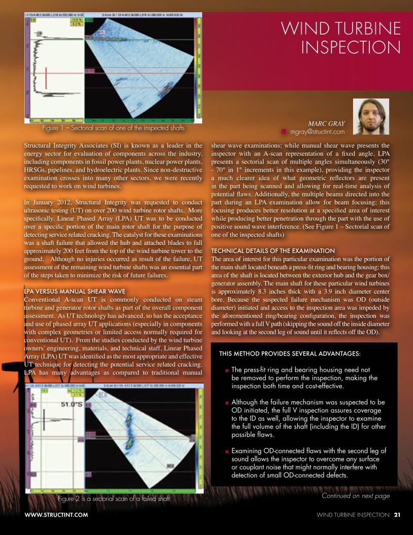
shear wave examinations; while manual shear wave presents the inspector with an A-scan representation of a fixed angle, LPA presents a sectorial scan of multiple angles simultaneously (30° - 70° in 1° increments in this example), providing the inspector a much clearer idea of what geometric reflectors are present in the part being scanned and allowing for real-time analysis of potential flaws. Additionally, the multiple beams directed into the part during an LPA examination allow for beam focusing; this focusing produces better resolution at a specified area of interest while producing better penetration through the part with the use of positive sound wave interference. (See Figure 1 – Sectorial scan of one of the inspected shafts) TECHNICAL DETAILS OF THE EXAMINATIONThe area of interest for this particular examination was the portion of the main shaft located beneath a press-fit ring and bearing housing; this area of the shaft is located between the exterior hub and the gear box/generator assembly. The main shaft for these particular wind turbines is approximately 8.3 inches thick with a 3.9 inch diameter center bore. Because the suspected failure mechanism was OD (outside diameter) initiated and access to the inspection area was impeded by the aforementioned ring/bearing configuration, the inspection was performed with a full V path (skipping the sound off the inside diameter and looking at the second leg of sound until it reflects off the OD).
Figure 1 – Sectorial scan of one of the inspected shafts
Figure 2 is a sectorial scan of a failed shaft
22 WIND TURBINE INSPECTION 8 7 7 - 4 S I - P O W E R
In preparation for the inspections, an ultrasonic beam plotting tool was used to simulate how the ultrasound would behave once it was introduced into the shaft. Knowing that the previous failures on these shafts occurred near the ends the bearing housing, the necessary setback and angle range could be determined to assure full coverage of the area of concern. (See Figure 3 – Beam Plot)
Figure 3 - Beam Plot
A team of seven qualified phased array examiners were assigned to the project consisting of two Level III and five Level II certified personnel. While the support staff concentrated on project management and logistical issues, the examiners were able to focus on the safety and quality aspects of the tasks at hand. Well organized SI project teams ensure that an efficient and thorough assessment is made onsite while providing offsite expertise and support necessary to meet our client’s needs in a comprehensive fashion.
RESULTS AND CONCLUSIONSOut of the 214 shafts inspected, only one shaft revealed an ultrasonic indication that raised concerns with the inspectors. Using a more refined calibration to interrogate this indication with more detail (narrowing the screen range, increasing the angle resolution, etc.), it was determined that this indication was not in the area of concern for this particular inspection; specifically, the indication was on or near the ID of the shaft, far from the OD-connected flaws that caused the previous failure.
The original Request for Proposal provided by the client specified that the project should be completed in eighteen days. Despite a long and detailed calibration process (which was necessary for such a complex examination), several weather delays, and other setbacks out of the control of those involved, we completed the project in the estimated eighteen days. This goal was achieved through the willingness of the inspectors to increase production on those days where this was possible, despite the physical hardships involved (e.g., climbing four towers in one day to make up for a day where it was only possible to climb one tower). Providing the client with a final product that meets or exceeds their inspection needs, and their fiscal and logistical needs is the cornerstone of Structural Integrity.
Calibration Block
Although the theoretical beam plot can be used to establish general parameters for the examination, final adjustments required to obtain the optimum signal response from the area of interest were made using a representative calibration standard produced from a section of the failed rotor shaft. Figure 4 shows the calibration standard and some of the OD surface calibration targets used to validate the LPA technique. ACCESS AND SAFETYNot the least of our concerns going into this examination was the safety of all personnel involved. Through the help and support of the wind technicians on site and off-site coordination efforts ,we achieved an incident-free inspection. Daily safety “tailboard” meetings, discussion and execution of proper climbing techniques, stoppage of inspections if wind conditions became dangerously high, and the use of proper fall arrest and climbing equipment were just some of the steps utilized by on-site personnel to assure a safe working environment.
A TEAM EFFORTAs with all projects executed by SI’s Technical Support Unit, internal teamwork is an essential part to achieving success. Everything from the materials and engineering review of documentation of the failure (photographs, sketches, and drawings) to the technical development and project management all aided in the successful implementation of an effective UT examination process. Although not always obvious to the end customer, each project is supported by an extensive group of engineering, materials, and NDE experts, as well as the management and administration personnel offsite.
The EPRI Materials Reliability Program (MRP) has an ongoing program (MRP-146) to help PWR owners manage thermal fatigue concerns in normally stagnant, non-isolable reactor coolant system (RCS) branch lines. The specific thermal mechanism addressed by MRP-146 is possible cyclic stratification during normal plant operation caused by swirl penetration. MRP-146 contains several “needed” requirements as part of the NEI 03-08 materials initiative. In short, branch lines found to be susceptible to thermal cycling require augmented inspection at an interval defined by MRP-146. Last summer, MRP-146 Revision 1 was published and changes to the report were presented to the NRC this past January.
An important aspect of the MRP-146 program is how susceptible branch lines are categorized. Branch lines attached to the top or side (up-horizontal, UH
UH/H configurations, Revision 1 now offers an option for the inspection interval to be defined without analysis.
MRP-146 Revision 1 also contains updated guidance for monitoring (both for temperature and in-leakage), examination volumes and thermal fatigue mitigation. The mitigation content has been significantly increased including specific application examples.
Structural Integrity has been involved with the MRP-146 program since its inception and has supported many plants with their MRP-146 actions. This support includes branch line screening, thermal fatigue evaluation, heat transfer analysis, deviation support and interpretation of monitoring data.
and horizontal, H) of the RCS piping are managed differently than branches connected to the lower half (down-horizontal, DH) of the RCS piping. As such, the “needed” requirements for UH/H and DH configurations are now specified in separate tables in Revision 1. Although there are significant changes from previous MPR-146 requirements, no additional plant activities are required by Revision 1. The timeframe for completing these requirements remains unchanged.
UH/H configurations require in-leakage toward the RCS piping to interact with swirl penetration for thermal fatigue to be of concern. Hence, Revision 1 now focuses more on in-leakage prevention as opposed to analyzing the severity of the thermal fatigue potential to define an augmented inspection interval. Because operating experience strongly suggests that usage accumulation in DH configurations is slower than in
OVERVIEW OF MRP-146 REVISION 1 CHANGES 23WWW.STRUCTINT.COM
Managing Thermal Fatigue
24 COMPREHENSIVE GENERATOR INSPECTION SERVICES 8 7 7 - 4 S I - P O W E R
Mechanical condition assessment for any component is a two-part process. First, an effective, accurate Non-Destructive Evaluation (NDE) inspection is needed to detect and characterize potentially detrimental flaws. The inspection must be followed by an analytical assessment to characterize the influence of detected conditions on the component’s remaining life.
When we’re inspecting generator bores, retaining rings, generator dovetail, TIL-1292 (Eddy Current and Ultrasonic techniques) and under coupling keyways, multiple disciplines of NDE techniques are needed. Phased array ultrasonic, TOFD, mode-converted L-wave, and eddy current are a few options to consider. Once obtained, then we use a complete suite of analysis software such as SAFER-PC for rotor forgings and RRingLife for retaining rings. These capabilities cover mechanical assessment for generator rotating components.
Generator rotors and stators are also inspected for electrical anomalies. The most common problems occurring with generator rotors are shorted turns and field grounds. Similarly with generator stators, issues related to electrical shorts and grounds can affect unit performance and longevity.
A comprehensive assessment package will pull all the inspection and analysis together for full evaluation.
As with mechanical assessments of generator rotors, electrical assessments contribute toward assurance of continued reliable generator performance over the next operational cycle. Awareness of previous analyses and inspection results, unit specific operating events, industry experience with similar units, and OEM recommendations, can be considered with current inspection results and analyses to make an informed decision on unit operability. Early identification of problems is helpful for dealing with minor issues before they become major problems with the potential
for dangerous and catastrophic failures.
Typical field winding (rotor) problem areas include shorts, grounds and degraded connections. Periodic electrical inspections with the unit off-line can identify these conditions. An off-line Recurrent Surge Oscillograph (RSO) test, performed during an outage, detects potential degradation of the inter-turn insulation and ground faults. In some cases, field winding deficiencies only occur during operation and cannot be detected and assessed with the unit off-line. For these situations, the on-line Rotor Flux Test locates and monitors inter-turn faults without the need for open circuit or visual inspection.
Generator stator inspections identify mechanical and electrical issues contributing to generator performance loss. As an example, loose stator wedges allow stator bar movement, contributing to premature stator winding damage and failure. A wedge-tap test is used to assess wedge tightness and the need for tightening or replacement of wedges to mitigate the problem. An Electromagnetic Core Imperfection Detection (EL-CID) test is used to detect circulating currents resulting from damaged stator core lamination insulation. Other processes for evaluation of the stator include visual inspection, Partial Discharge (PD), Partial Discharge Inception Voltage (PDIV) and Partial Discharge Extinction Voltage (PDEV), capacitance and dissipation factor, TVA probe, ultra probe, corona scope, and DC Ramp tests.
Structural Integrity formed an alliance with Kinectrics, formerly the Research Division of Ontario Hydro (one of North America’s largest electric utilities), to combine our core offerings and provide a comprehensive generator assessment package covering a wide range of machines, from 4160 V motors for nuclear and conventional applications, through hydraulic generators, to 1200 MW generators.
EXPERIMENTAL MODAL ANALYSIS OF SAFETY RELIEF VALVE
Structural Integrity collaborated with Wyle Laboratories to perform an experimental modal analysis of a Main Steam Line Safety Relief Valve to help our client identify the cause of unexpected valve actuations. Our work included custom fabrication of valve gag and stinger, cooling block assemblies, high temperature instrumentation, and extensive instrumentation of valve internals. We performed testing in a radiologically controlled area with full pressure and temperature at the valve inlet (~1000 psig, 550 ˚F). The experimental results provided valuable insight into the dynamic characteristics of the valve disk and spindle assembly, which could then be used by the utility to assess the potential for mechanical amplification of the known SRV standpipe acoustic resonances in the main steam system.
STRAIN GAGE DATA COLLECTION FOR EPU BASELINE POWER ASCENSION
In the fall of 2011, Structural Integrity supported a U.S. nuclear power plant with the acquisition of vibration data during baseline measurement in preparation for implementation of extended power uprate (EPU). EPU is a type of power up-rate that typically increases reactor power by 15% to 20%. Specifically, we used our previously installed 32-channel strain gage data acquisition system which collected vibration data related to pressure pulsations in the main steam lines. The data was collected throughout power ascension to the current licensed thermal power level, which we then used in a comprehensive data analysis. The results are used in a computation that will determine the likelihood of encountering a resonance condition for the expected future EPU steam flow in the main steam lines.
VIBRATION CORNER 25WWW.STRUCTINT.COM
Accelerometer Mounting Locations
Spindle Excitation
26 LEVERAGING YOUR BURIED PIPING PROGRAM FOR ENHANCED GROUNDWATER PROTECTION 8 7 7 - 4 S I - P O W E R
LEVERAGINGYOUR BURIED PIPING PROGRAM
for Enhanced Groundwater ProtectionBy: STEVE BIAGIOTTI■ [email protected]
The Underground Piping and Tanks Integrity Initiative (UPTI) and Ground Water Protection Initiative (GPI) (referred to collectively as the “Enhanced Inspection and Environmental Monitoring Initiatives”) are both formal industry commitments at the Chief Nuclear Officer (CNO) level (as discussed in NEI 11-07, Dec 2011). The two complementary initiatives are intended to enhance public and regulatory confidence by minimizing unintended leaks on site. When implemented, there must be a high level of coordination and involvement. NEI, EPRI and others in the industry are working together to improve this coordination. An easy and effective platform for accessing and sharing data is key to successfully integrating and leveraging the vast amount of information both groups continually manage. Thanks to EPRI’s leadership, the industry has a standard database model available free to all U.S. nuclear power plants – BPWorks™ 2.0. This database is capable of managing asset information (i.e., design & operational details as a function of consequences), as well as information on environment characteristics, inspection results and monitoring observations. Buried pipe program owners need to understand the environment (e.g., soil characteristics), while the groundwater program owners are interested in buried pipe location, proximity to wells and its contents. Working together, improved results can be achieved.
Structural Integrity, working with our MAPPro User Community, has supplemented the buried pipe database with additional tables to manage the storage of monitoring well information (e.g., name, location, depth, measured radioisotope concentrations, nearest pipe, nearest pipe with radiological content, etc.) plus includes the automation of calculations needed for NEI 07-07 program management.
Figure 1
LEVERAGING YOUR BURIED PIPING PROGRAM FOR ENHANCED GROUNDWATER PROTECTION 27WWW.STRUCTINT.COM
In 2007/2008, under the requirements of NEI 07-07, sites evaluated and prioritized systems, structures, and components (SSCs) and work practices for their potential to cause soil or groundwater contamination as a key aspect of the baseline program. This allowed plant management to prioritize possible efforts to eliminate or reduce the potential for groundwater contamination that may be caused by SSCs or work practices. The basis for a prioritization model, shown in Figure 2, was provided in the EPRI Guide to assist the licensee in quantitatively determining the potential for contamination.
The MAPPro User Community has allocated significant funds in 2012 to enhancing and creating new software applications to meet this evolving need.
In addition, we are increasing our accessibility options to include remote/web access to further increase the ease with which users can use these tools.
For more information on becoming a member of the MAPPro User Community or to learn more about the tools available to support the Coordination of the Enhanced Inspection and Environmental Monitoring Initiatives, please contact us at: [email protected].
Figure 4 below Figure 3 to the right
Figure 5
The factors that determine the relative prioritization of SSCs or work practices are subject to change over time. These changes may result from aging equipment, modifications to procedures and processes, changes in local, state or federal regulations, changes in the makeup or viewpoint of stakeholders, and other factors. Consequently, the relative risk factors that contribute to an SSC’s or work practice’s priority ranking should be re-evaluated periodically. NEI 07-07 recommends the SSCs be reevaluated every five years. Reinspections will occur for most sites in 2012 or 2013
Figure 2
28 STRUCTURAL INTEGRITY: FATIGUEPRO 4.0 8 7 7 - 4 S I - P O W E R
As we’ve reported previously, Structural Integrity is in the process of rolling out a new-generation fatigue monitoring software system for nuclear power plants. We have some updates since the last article of interest to all current and prospective users of the software.
First, the Structural Integrity-authored EPRI technical report 1022876, “Stress-Based Fatigue Monitoring: Methodology for Fatigue Monitoring of Class 1 Nuclear Components in a Reactor Water Environment,” was reviewed by utility and industry experts and published by EPRI in November 2011. This non-proprietary
report provides the technical basis for stress-based fatigue (SBF) monitoring. Specifically, the new SBF methodology, which was presented to the NRC in a January 5th meeting in Washington, includes six component stress calculations and minimizes other areas of analyst and user judgment, in response to NRC Regulatory Issue Summary (RIS) 2008-30. The methodology also addresses the concerns in NRC RIS 2011-14 by obviating the need for analyst judgments associated with stress peak and valley selection. Finally, this new SBF technology provides for automatic calculation of environmentally-assisted fatigue (EAF) in accordance
with the latest NUREG¬-1801, “Generic Aging Lessons Learned (GALL)” report, Regulatory Guide 1.207 for new plants, and the latest consensus about analytical techniques from EPRI’s Environmental Fatigue Expert Panel.
Software development itself was internally funded by SI. The new version, called SI:FatiguePro 4.0, is owned and licensed by Structural Integrity, while implementing the EPRI SBF methodology. However, FatiguePro 3.0, developed and licensed by EPRI, will continue to be supported by both SI and EPRI in the same way it always has been.
In addition to the significant technical improvements associated with the SBF calculations, SI:FatiguePro 4.0 includes new features, such as:
■ A new “landing page” as the default window, summarizing the latest, most pertinent results.
■ HTML reporting for easier copying and printing. ■ New and improved projected cycle and fatigue summary reports and charts.
■ A Transient Library module to aid with simulations and data recreation. ■ Improved database performance using SQLite, an open, lightweight and high performance database.
■ Preservation of manually added events following an analysis “undo.” ■ 64 bit Windows operating system support. ■ Parallel processing (multiprocessor) support for high performance computations.
We are currently under contract to provide the first SI:FatiguePro 4.0 systems to Calvert Cliffs Units 1/2, a US PWR, and Shin-Kori Units 3/4, a new APR1400 currently under advanced stages of construction in South Korea.
FatiguePro is the most widely used fatigue monitoring system for nuclear power plants, with installations at 88 units worldwide, and at plant types including Westinghouse PWR’s, General Electric BWR’s, C-E PWR’s, B&W PWR’s, and CANDU heavy water reactors.
Please contact Tim Gilman [email protected] if you have any questions.
Collectively, Structural Integrity has a lot of useful knowledge, but what about the useless? Impress your coworkers by sending us your most trivial, entertaining science and engineering knowledge for the next edition of Cool Facts.
End of the World PredictionsAccording to a loose interpretation of the Mayan calendar, the world will end on December 21, 2012. In honor of this event, I have collected a small sample of other end of the world predictions. After all, predicting the end-of-the-world is the worst job in history. You get it wrong and face ridicule and scorn. You get it right and there’s no one left to see you gloat.
The end is coming, that much is clear. And just like the lottery, someone might get it right but it won’t be me. Here’s a short list of famous people and their predictions: Nostradamus (1999, 3797), Martin Luther (1600), Christopher Columbus (1658), John Napier (1688, 1700), Sir Isaac Newton (2060).
Radio host, Harold Camping has made 5 predictions to date.
Tenacity is rewarded in most endeavors, but not all.
1806 The Prophet Hen of LeedsLeeds, England, 1806: a hen began laying eggs
on which the phrase “Christ is coming” was etched. A prankster had written on the eggs
and reinserted them back into the hen
None. We still don’t know which came first, the chicken or the egg.
March 10,1982 John Gribbin and Stephen Plagemann, authors of The Jupiter Effect (available from, Amazon.com starting at $0.01 used), claimed that the
gravitational forces of the aligned planets would destroy the earth.
“If all the planets were in a straight line, it would raise the tide only one six hundredths of an inch” – Myles Standish, JPL. Note that December 21, 2012, also coincides with an alignment of the
planets, so get your high-waters on.
5,000,000,000 End of the Sun’s current phase Default end of the world scenario
SI NUCLEAR PLANT INTEGRITY WORKSHOP Structural Integrity’s Nuclear Plant Services unit is hosting a Nuclear Plant Integrity Workshop August 22-23, 2012, in Charlotte, NC. Join our engineering experts as we discuss key topics in the nuclear industry, such as fatigue management, license renewal and aging management programs and reactor internals. Registration is free and ends August 6, 2012. For more information or to register, visit www.structint.com/nps-workshop.
CORROSION AND MIC CONTROL TRAININGStructural Integrity Associates will conduct its Corrosion and MIC Control training June 18-19, 2012, in Charlotte, NC. This course is offered in conjunction with EPRI’s Microbiologically Influenced Corrosion Course and will review all aspects of aqueous corrosion. Registration
is $945 and includes breakfast and lunch both days as well as all presentation materials. For more information or to register for the course, visit www.structint.com/MIC-training
BOILER INTEGRITY MANAGEMENT WORKSHOPStructural Integrity Associates and Diamond Technical Services (DTS) co-hosted the Boiler Integrity Management Workshop February 22-23 in Tampa, Florida. Over 30 people attended the inaugural workshop at the Wyndham Tampa Westshore. After welcoming remarks from Laney Bisbee, President and CEO of Structural Integrity, experts from Structural Integrity and DTS gave several presentations over two days on best practices of boiler integrity management, outage inspection philosophies and post-outage documentation. Both days offered a Q&A panel to promote valuable discussion among attendees about boiler integrity management. “I learned a lot about boiler integrity management and enjoyed my two days here,” said Mauricio de la Torre, Plant Manager at TECO Guatemala.
In 2011, Structural Integrity and DTS signed a memorandum of understanding. Working together, we offer a comprehensive boiler integrity management program. For more information about boiler integrity management, visit www.structint.com/bim or call 1-877-4SI-POWER.
30 MAOP VERIFICATION 8 7 7 - 4 S I - P O W E R
MAOP VERIFICATION
On February 16th, Structural Integrity Associates and Gas Transmission Systems presented a webinar, MAOP Verification Best Practices. Our webinar discussed lessons learned from MAOP verification projects with two different gas transmission pipeline operators. Topics covered included: overview of recent legislation and deadlines, project scope, data requirements, targeted records and record scanning, data capture and management, missing data, contradictory records, and MAOP calculation.
MAOP VerificationCalculated vs. CurrentMAOP VerificationCalculated vs. Current
Mitigation TrackingMitigation Tracking
Access to images
MAOPAssessment
Engine
ScannedImages(Image ofsource
record foreach key
dataelement)
ScannedImages(Image ofsource
record foreach key
dataelement)
A recording of the webinar is available from Structural Integrity’s website:http://www.structint.com/what-we-do/pipeline-services/webinars/si-past-webinars/best-practices-of-an-maop-verification-program
INDUSTRY EVENTS
STRUCTURAL INTEGRITY NEWS 31WWW.STRUCTINT.COM
STRUCTURAL INTEGRITY NEWS
INPO RECEIVES TRAINING ON APECIn January 2012, Andy Smart (NACE Corrosion and Cathodic Protection Specialist) and Steve Biagiotti, PE were invited to provide specialized training to approximately a dozen INPO inspectors at their Atlanta office on the APEC (Area Potential Earth Current) indirect inspection survey technique as part of the buried pipe analysis process. The training was part of a weeklong series that helped inspectors better understand the issues they may face during inspections.
APEC is a specialized inspection technique used in the nuclear power industry to evaluate the potential for degradation in congested buried piping networks. The results aide site buried pipe program owners by prioritizing excavations to reveal the greatest potential for degradation in accordance with the reasonable assurance process described in NEI 09-14, Guideline for the Management of Underground Piping and Tank Integrity. APEC has been performed at more than a dozen U.S. nuclear sites for Exelon, Constellation, NextEra, Luminant, DTE, TVA and Entergy. For more information on the APEC process, www.structint.com/MapProBrochure/#/12/.
CLIENT SATISFACTION SURVEYOne of Structural Integrity’s core values is quality: quality in service, engineering, consulting and everything we do. To make sure our quality focus meets your needs, we would appreciate your participation in our client satisfaction surveys.
OUR CLIENT SATISFACTION SURVEYS ARE TWO-PRONGED:1. We will be asking our clients to complete a brief 4-question survey about how Structural
Integrity performed on projects over the past three years.2. As we complete projects for clients, we will also ask for your feedback.
If you have any questions about our client satisfaction surveys, please give us a call at 1-877-4SI-POWER (1-877-474-7693). Thank you in advance for your time and for your responses. We look forward to exceeding your expectations on future opportunities.
NACE CP LEVEL III CERTIFICATION COMPLETEDJoin us in congratulating Pete Wood, in our Denver Pipeline Services Department, for successfully completing the NACE Cathodic Protection Technologist (Level III) training and certification program. He joins an elite group of less than 150 people in the U.S. with this certification.
The NACE CP Level III certification ensures knowledge of theoretical concepts and practical application of cathodic protection (CP), with a strong focus on interpretation of CP data and troubleshooting. This level of experience and knowledge ensures that Structural Integrity projects achieve useful and meaningful project results.
Cathodic Protection (CP) is the practice of controlling the tendency of a metal structure in contact with its environment (i.e., pipe in soil, rebar in concrete, pilings or ship hulls in water, etc.) to freely corrode by releasing current into the ground for collection by the structure, thereby reversing the electrochemical driving force for that material to oxidize (i.e., Fe<>Fe 2+ + 2e-).
INDUSTRY EVENTS
IAN PERRIN RECENTLY JOINEDSTRUCTURAL INTEGRITY ASSOCIATES Ian Perrin recently joined Structural Integrity Associates as Vice President of Fossil Plant Services. He will lead our Fossil Plant Services division and continue our successful efforts servicing domestic and international fossil plants worldwide. He joined us from Alstom, USA, where he was Manager of the Boiler Pressure Parts Critical Technology group.
His top priorities are to continue to grow depth and breadth in our integrated service solutions for fossil plants drawing on the combined capabilities of materials, mechanical integrity and non-destructive testing, while creating scalable management systems to support this growth. The combined cycle market will be a particular focus because of the increasing need for these plants to endure flexible, cyclic operation. Please join us in welcoming Ian to Structural Integrity.
11515 Vanstory Drive Suite 125Huntersville, NC 28078
For more information on these events and Structural Integrity, go to:
www.structint.com/news-and-views-32
3 19 2012
8 7 7 - 4 S I - P O W E R 8 7 7 - 4 7 4 - 7 6 9 3
WORKSHOPS:Nuclear Plant Integrity WorkshopCharlotte, NC, August 22-23, 2012Register now at www.structint.com/nps-workshop
TRAINING:Corrosion and MIC ControlCharlotte, NC, June 18-19, 2012www.structint.com/mic-training
WEBINARS:Flaw Evaluation Strategies to Improve the Value of ExcavationsApril 19, 2012 2:00PM ESTPresented By: Eric HoustonRegister now at https://structint.webex.com
Turbine Generator Condition AssessmentApril 25, 2012, 2:00 PM ESTPresented By: Paul ZayicekRegister now at https://structint.webex.com
TRADESHOWS AND CONFERENCES:NAES Vendor FairSan Diego, CA, May 14, 2012
3rd International Conference on NPP Life Management (PLiM)**Silver Sponsor**Salt Lake City, UT, May 14-18, 2012SI Presenters: Keith Evon, Dave Gerber, Terry Herrmann and George Licina
EPRI 9th International Conference on NDE **Bronze Sponsor**Seattle, WA, May 22-24, 2012Visit us at Booth #107SI Presenters: Tim Griesbach, Jagannath Hiremagalur, Jeff Milligan, Dave Overton, Roger Royer, Jason Van Velsor
EPRI Welding and Repair Technology for Power PlantsMarco Island, FL, June 26-28, 2012SI Presenters: Bud Auvil, Kim Bezzant, Jeff Henry, Dick Smith
103rd IDEA Annual Conference & Trade Show: "District Energy/CHP 2012"Chicago, IL, June 30-July 3, 2012Visit us at Booth #87
EPRI Buried Pipe Integrity GroupMemphis, TN, July 9-11, 2012
ASME Pressure Vessels and Piping ConferenceToronto, Ontario, Canada, July 15-19, 2012
EPRI International PWR BWR (MRP) Conference and Exhibition **Platinum Sponsor**National Harbor, MD, July 16-19, 2012
SGA Operating ConferenceFort Worth, TX, July 23-25, 2012
EPRI Turbine Generator Workshop and Vendor ExpoChattanooga, TN, August 13-17, 2012
NACE Central Area ConferenceChicago, IL, August 26-29, 2012
NACE Corrosion Technology WeekNew Orleans, LA, September 16-20, 2012
Scan the QR Code for more information
For career opportunities with Structural Integrity, visit:www.structint.com/jobs