Be126 OEM's Manual V000 - 20 Oct - 2015 page 1 1 BE126 Diesel Fire Pump Controller The information in this document may be subject to change without notice. No part of this document may be copied or reproduced in any form or by any means without the prior written consent of Bernini Design Company. Bernini Design assumes no responsibility for any errors which may appear in this instruction manual or in the wiring diagrams. Although Bernini Design has taken all possible steps to ensure that the User Manual is completely, error free and up-to-date, we accept that errors may occur. Any future updates will be included in our official website www.bernini-design.com. If you encounter problems with this instruction manual, please contact us. Customer Support BERNINI DESIGN SRL ITALY e-mail: [email protected]mobile: ++40 721 241 361. Tel:++39 335 7077148. Warranty Bernini Design SRL (hereinafter BD) warrants that Be124 shall be free from defect in material or workmanship for a period of 3 years from the BD delivery date. BD shall, at its discretion, repair or replace the product without charge. BD shall return the Be124 to the buyer with the Default parameters at no extra charge. The buyer shall furnish sufficient information on any alleged defects in the product, so as to enable BD to determine there cause and existence. If the Be124 is not defective, or the product is defective for reason other than covered by this warranty, the buyer will be charged accordingly. This warranty shall not apply if the Be124 has not been used in accordance with the User Manual and other operating instructions, particularly if any defects are caused by misuse, improper repair attempts, negligence in use or incorrect handling. Then the purchase is non-refundable. This equipment complies with the EMC protection requirements !! WARNING !! High voltage is present inside the Be124. To avoid any electric-shock hazard, operating personnel must not remove the protective cover. Do not disconnect the grounding connection. The Be124 can start the engine at anytime. Do not work on equipment, which is controlled by the Be124. When servicing the engine, disconnect the battery and battery charger. We recommend that warning signs be placed on equipment indicating the above. !! WARNING !! Author: Bernini Mentore !!! WARNING !!! MAINS VOLTAGE IS EXPOSED WITHIN THE BE124 AND ANCILLARY CIRCUITRY EVEN WHEN THE LED INDICATORS PLACED ON THE FRONT PANEL ARE OFF. http://www.bernini-design.com
Transcript
Be126 OEM's Manual V000 - 20 Oct - 2015 page 1
1
BE126 Diesel Fire Pump Controller
The information in this document may be subject to change without notice. No part of this document may be copied or reproduced in any form or by any means without the prior written consent of Bernini Design Company. Bernini Design assumes no responsibility for any errors which may appear in this instruction manual or in the wiring diagrams. Although Bernini Design has taken all possible steps to ensure that the User Manual is completely, error free and up-to-date, we accept that errors may occur. Any future updates will be included in our official website www.bernini-design.com. If you encounter problems with this instruction manual, please contact us.
Customer Support BERNINI DESIGN SRL ITALY
e-mail: [email protected] mobile: ++40 721 241 361. Tel:++39 335 7077148. Warranty Bernini Design SRL (hereinafter BD) warrants that Be124 shall be free from defect in material or workmanship for a period of 3 years from the BD delivery date. BD shall, at its discretion, repair or replace the product without charge. BD shall return the Be124 to the buyer with the Default parameters at no extra charge. The buyer shall furnish sufficient information on any alleged defects in the product, so as to enable BD to determine there cause and existence. If the Be124 is not defective, or the product is defective for reason other than covered by this warranty, the buyer will be charged accordingly. This warranty shall not apply if the Be124 has not been used in accordance with the User Manual and other operating instructions, particularly if any defects are caused by misuse, improper repair attempts, negligence in use or incorrect handling. Then the purchase is non-refundable.
This equipment complies with the EMC protection requirements
!! WARNING !!
High voltage is present inside the Be124. To avoid any electric-shock hazard, operating personnel must not remove the protective cover. Do not disconnect the grounding connection. The Be124 can start the engine at anytime. Do not work on equipment, which is controlled by the Be124. When servicing the engine, disconnect the battery and battery charger. We
recommend that warning signs be placed on equipment indicating the above.
!! WARNING !!
Author: Bernini Mentore
!!! WARNING !!! MAINS VOLTAGE IS EXPOSED WITHIN THE BE124 AND ANCILLARY CIRCUITRY EVEN
WHEN THE LED INDICATORS PLACED ON THE FRONT PANEL ARE OFF.
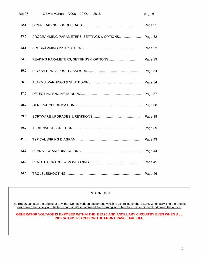
The Be126 can start the engine at anytime. Do not work on equipment, which is controlled by the Be126. When servicing the engine, disconnect the battery and battery charger. We recommend that warning signs be placed on equipment indicating the above.
GENERATOR VOLTAGE IS EXPOSED WITHIN THE BE126 AND ANCILLARY CIRCUITRY EVEN WHEN ALL
INDICATORS PLACED ON THE FRONT PANEL ARE OFF.
Be126 OEM's Manual V000 - 20 Oct - 2015 page 7
7
Section 1.0 - INTRODUCTION
The Be126 fire pump controller is designed to control and monitor 12 or 24 volt, diesel fire pump engine used in NFPA 20 or UNI-EN 12845 compliant firefighting application. It features state-of-art multiprocessor stucture providing embedded water pressure data logger capable of storing up to 31 days of data. Be126 interfaces with standard or SAE J1939 compatible diesel engines. The Be126 monitors, displays and records engine information as well. The Be126 automatically starts the diesel engine from water pressure control or non-automatically from manual electric control. It initiates a weekly program test of the system and records analog water pressure measurements. The Be126 features RS232 and RS485 serial interfaces. You can connect the Be126 to the Internet via TCP-IP server. The Be126 displays voltage and current of the batteries when you connect MOD-BUS battery chargers. The Be126 monitors the Mains. You can use the Be126 controller in standard diesel engine pump water station by enabling the ‘Engine Protection Mode’.
7 BATTERY VOLTAGE ALARMS 16 DISPLAY ARROWS 25 PILOT SOLENOIDS
8 ENGINE TEMPERATURE 17 [AUTO] BUTTON 26 [HOME] PUSH BUTTON
9 FAIL TO START ALARM 18 PUMP TEST BUTTON 27 [LAMP TEST] PUSH BUTTON
LAMP
TEST HOME
START
1START
2 OFF
V
BT1
BT2
V
A PUMP
RUN
START1
START 2
LPS
TEMPERATURE
A
AUTO
MENU
MAN
TEST
F1
F2 F3
F4
27 26 2324 22 20 19
1
2
3
4
5
6 7 8 9 10 11 12 13
16
18
15
21
17
25
14
Be126 OEM's Manual V000 - 20 Oct - 2015 page 8
8
Section 2.0 - SELECTING AN OPERATIONAL MODE
The mode of operation is selected via the [OFF], [MAN] ,and [AUTO] push buttons.When you remove and re-apply the DC supply, the controller enters automatically the OFF mode of operation except when the Be126 was in AUTO mode of operation before shutting down the battery supply. 2.1 - OFF mode of operation: description Push the [OFF] button to enter the OFF mode of operation. You clear all alarms and reset the system. In OFF mode of operation you are allowed to program the controller (see 33.1). You can read the programmed parameters & settings, at any time, not only in OFF mode. To open the main menu, push the [MENU] button. You can browse the list of the sub-menus by using the [ ↑ ] or [ ↓ ] push buttons (see 4.0). 2.2 - MANUAL mode of operation: starting the engine Push the [MAN] button. The display will indicate the message [MANUAL]. Push the [START 1] button if you want to start the engine using the BATTERY SET 1. Push the [START 2] button if you want to use the BATTERY SET 2. Push and hold the button until engine starts. You can program a [CRANK DELAY] and [PREGLOW] prior activating the starter motor. The Be126 terminates the crank according to your settings (see 13.0 & 14.0). In NFPA/EN applications, the Be126 ignores the [PREGLOW] setting. In case the battery voltage drops below 6 volts, the Be126 may reset the software. The controller will restart in OFF mode of operation. 2.2.1 Note for NFPA or EN12845 In case of fire, the start push buttons are not inhibited (or start is not terminated) by the ‘Engine Running Status’ (see section 37.0). When ‘Engine Protection’ mode is selected (in other words, not in NFPA/EN mode), the Be126 terminates the crank according to your settings.The crank termination parameters, included in the [ENGINE PARAMETERS] menu (see 13.0), are: [CRANK VDC] [CRANK RPM] [CRANK CANBUS] NOTE: before programming the [CRANK RPM] you are required to set up the teeth-count [PICKUP/W RATIO] (see14.0.3) If the engine stops for an unknown reason, the Be126 will trigger the alarm [UNEXPECTED STOP WARNING]. 2.2.2 NFPA/EN12845 From the MANUAL mode of operation you can enter the AUTO mode of operation by pushing the [AUTO] button at any time. The AUTO mode will automatically control of the entire system. 2.2.3 Engine Protection Mode(*) From the MANUAL mode of operation you can enter the AUTO mode of operation by pushing the [AUTO] button only if there is no active shutdown or alarm. To enter the AUTO mode, you are required to clear the alarm(s). (*)The ‘Engine Protection Mode’ is active when you connect to battery minus the input JF-10. In this way you let
the Be126 stop the engine in case of alarms (supposing you correctly programmed the alarm parameters).
Be126 OEM's Manual V000 - 20 Oct - 2015 page 9
9
2.2.4 - MANUAL mode of operation: stopping the engine To stop the engine you have to push the [OFF] button. The Be126 removes the power to the ‘Fuel Solenoid’ (output JC-8). In case you use an energized to stop solenoid, the Be126 activates the output JC-4 according to [STOP SOLENOID] timing (see the [ENGINE PARAMETERS] sub-menu in section 13.0.5). When you push the [OFF] button, you enter the OFF mode of operation as well. The Be126 clears all alarms and reset the system. An optional way to stop the engine is to enter the AUTO mode of operation. If there is no fire alarm (all sources of start have been returned to normal) the Be126 will shut down the engine after the [STOP DELAY] timing (see section 21.0.1). 2.3 AUTO mode of operation: description
The Be126 can start the engine at anytime. Do not work on equipment, which is controlled by the Be126. When servicing the engine, disconnect the batteries and battery chargers. We recommend that warning signs be placed on equipment indicating
the above.
Push the [AUTO] push-button until the yellow AUTO indicator illuminates (connect a lamp to JB-4 output); the display will evidence the message [AUTO]. The engine starts when the Be126 detects one of the following condition:
- the water pressure switch is open (digital input JF-4) - the water level switch is open (digital input JF-7) - the water pressure drops below the [START DEMAND] setting (see 19.01 & Input JM-1)
The yellow indicator >LPS< blinks when the Be126 detects a drop of pressure. The display will switch the message [START DEMAND OFF] to [START DEMAND ON]. The Be126 will initiate the start sequence after a [START DELAY] bypass time (see the [MISCELLANEOUS] menu 21.0.1). Depending on your settings, the engine will run at idle speed or it will run immediately at nominal speed. When the engine is running, use the display arrows to browse the instruments. If you get lost during navigation, push the [HOME] button: the display will open the ‘System Status Page’ that is the display home page. Based on your settings (NFPA-EN12845 or Engine Protection Mode), the Be126 may stop the engine in AUTO mode of operation when the pressure returns normal. You can stop the engine by pushing the [OFF] button. We remind you that in case you programmed the controller to work according to NFPA 20 specifications, only an OVERSPEED (see 14.0.2) condition can shut down the engine. All the others alarms provide only a warning . The Be126 will periodically test the engine if the scheduler is correctly programmed. During the test, the display will indicate the message [SCHEDULED TEST] (see 8.0). The engine will stop based on your settings. The [EVENT HISTORY] register records in real-time all sequences. You can browse the event log at any time (see section 7.0). When the Be126 is in AUTO mode of operation, you can carry out a test of the automatic system by pushing the [PUMP TEST] button. The Be126 will activate the drain to initiate a test. The sequences are very well described in the ‘TEST mode’ section (see 2.4). To find out more about AUTO mode of operation, consult the chapter 12 of the NFPA 20 Standard and sections 10.9.7---.13
of the EN 12845 Standard.
When you connect the input JF-10 to battery minus, the Be126 will activate the ‘Engine Protection Mode’ software. If you enable a shutdown (Oil pressure, Temperature, Fuel and so on), the engine will stop accordingly. Automatic START & STOP of the engine are driven by the status of the water pressure or water level. You can program different delays and options to start & stop the diesel engine. The [MISCELLANEOUS] menu (section 21.0) contains the basic settings. The ‘Engine Protection Mode’ will allow you to use Be126 to control and protect diesel engine in water pump station or irrigation systems.
Be126 OEM's Manual V000 - 20 Oct - 2015 page 10
10
2.4 TEST mode of operation description !!! WARNING: ENGINE MAY START IMMEDIATELY !!!! Be126 offers several ways of testing. It depends on the application: NPFA 20, EN12845 or ‘Engine Protection Mode’. Follow the instructions.
2.4.1 UNI EN 12845 MANUAL TEST FACILITY Every time you stop the engine after an automatic start, or after an automatic start shutdown, you are required to manually verify the circuits of the automatic start. You are required to wire an external push button to terminal JF-6 (Pump Manual Test Switch). When the condition to make the test comes true, the Be126 turns on the lamp 'OPERATE MANUAL START TEST BUTTON IF LAMP IS LIT'. After carrying out the test, the Be126 turns off the lamp. You are required to connect the lamp to terminal JC-4 (Manual Start Lamp). 2.4.2 UNI EN 12845 RESTARTING TEST UTILITY (Weekly Test) When the Be126 is in AUTO mode of operation, you have to periodically test the automatic system. Follow the instructions: • - Push the [PUMP TEST] button. • - The display indicates the message [TEST START]. • - The Be126 initiates the test by activating the DRAIN VALVE (output JB-5). • - The Be126 will start the engine when the sensor detects a drop of pressure (*). • - The engine will run for 20 minutes (you have to program the auto shut down). When you stop the engine, or after the automatic shutdown, the Be126 will activate the external lamp: 'OPERATE
MANUAL START TEST BUTTON IF LAMP IS LIT'. You are required to start manually the engine. Once the engine is running, the Be126 will turn off the lamp. We recommend that you consult the sections 10.9.7.1-2-3-4-5 of the UNI EN 12845 Standard. (*) Note. If, after a minute time, the pressure fails to drop down, the Be126 will trigger the alarm [TEST START] (see the section 21.0.2 to change the alarm delay if necessary).
2.4.3 NFPA 20 TEST FACILITY (Random Test) When the Be126 is in AUTO mode of operation, you can carry out a test of the automatic system: 1) Push the [PUMP TEST] button. 2) The display indicates the message [TEST START]. 3) The Be126 activates the DRAIN VALVE (output JB-5) to initiate a test. 4) The Be126 will start the engine when the sensor detects a drop of pressure (*). 5) The engine will run and eventually will stop according to your settings. (*) Note. If, after a minute time, the pressure fails to drop down, the Be126 will trigger the alarm [TEST START] (see
the section 21.0.2 to change the alarm delay if necessary).
2.4.4 NFPA 20 TEST FACILITY (Weekly Test) The Be126 features a [TEST SCHEDULER] menu that will weekly exercise the diesel engine (see 8.0). You can program a day of the week, hour and minutes to start the engine. You have to program in the same day, hour and minutes to stop the engine. At the programmed date & time, the ‘scheduler routine’ will activate the DRAIN VALVE (output JB-5) and will display the message [TEST START]. You can program a timeout (see the paramter [TEST FAILURE] that triggers the alarm [TEST FAILURE WARNING] in section 21.0.2). The engine will run for the programmed time and the [EVENT HISTORY] will record all events indicating date & time. The embedded data logger will record all events and the variation of pressure.
We recommend that you consult the chapter 12 of the NFPA 20 Standard.
Be126 OEM's Manual V000 - 20 Oct - 2015 page 11
11
2.4.5 ENGINE PROTECTION MODE TEST FACILITY You enable the ‘Engine Protection Mode’ by connecting the terminal JF-10 to battery minus. This setting is used in general purpose diesel water pump for various applications: farm irrigation systems, irrigation for agriculture, pumping stations for water supply systems, automatic diesel pumping stations. In these applications the Be126 plays the additional important role of protecting the diesel engine. You have at your disposal a wide choice of test options:
- start the engine directly by using the scheduler without using a drain valve - test the engine starting circuits holding the fuel valve closed - run the engine on a daily basis for a programmed time - test the engine at nominal or idle speed
The settings to configure test are included in the [MISCELLANEOUS] and [TEST SCHEDULER] sub-menu (see 8.0).
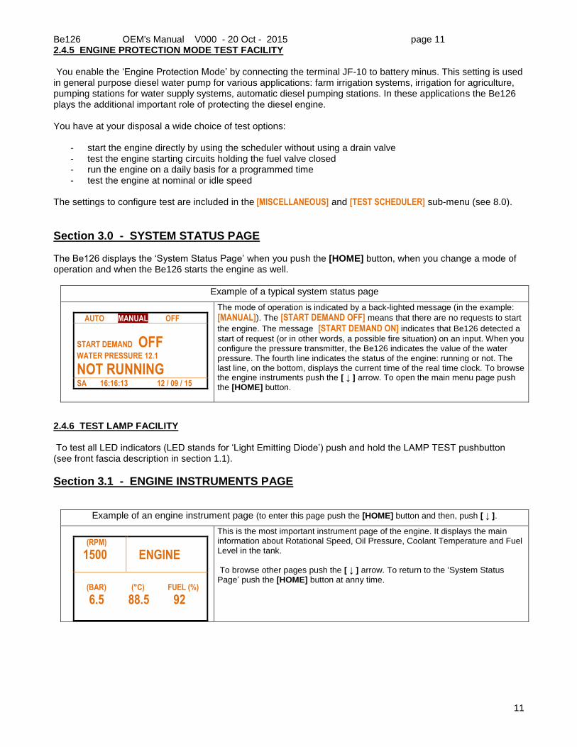
Section 3.0 - SYSTEM STATUS PAGE The Be126 displays the ‘System Status Page’ when you push the [HOME] button, when you change a mode of operation and when the Be126 starts the engine as well.
Example of a typical system status page
AUTO MANUAL OFF F
START DEMAND OFF
WATER PRESSURE 12.1
NOT RUNNING
SA 16:16:13 12 / 09 / 15
The mode of operation is indicated by a back-lighted message (in the example:
[MANUAL]). The [START DEMAND OFF] means that there are no requests to start
the engine. The message [START DEMAND ON] indicates that Be126 detected a
start of request (or in other words, a possible fire situation) on an input. When you configure the pressure transmitter, the Be126 indicates the value of the water pressure. The fourth line indicates the status of the engine: running or not. The last line, on the bottom, displays the current time of the real time clock. To browse the engine instruments push the [ ↓ ] arrow. To open the main menu page push the [HOME] button.
2.4.6 TEST LAMP FACILITY To test all LED indicators (LED stands for ‘Light Emitting Diode’) push and hold the LAMP TEST pushbutton (see front fascia description in section 1.1).
Section 3.1 - ENGINE INSTRUMENTS PAGE
Example of an engine instrument page (to enter this page push the [HOME] button and then, push [ ↓ ].
(RPM)
1500 F
ENGINE
(BAR) (°C) FUEL (%)
6.5 88.5 92
This is the most important instrument page of the engine. It displays the main information about Rotational Speed, Oil Pressure, Coolant Temperature and Fuel Level in the tank. To browse other pages push the [ ↓ ] arrow. To return to the ‘System Status Page’ push the [HOME] button at anny time.
Be126 OEM's Manual V000 - 20 Oct - 2015 page 12
12
Section 3.2 - MAINS INSTRUMENTS
To display this page push the [HOME] button and then, repeteadly push the [ ↓ ] button.
FREQ (HZ)
50.0 F
CCW
MAINS
L1(V) L2(V) L3(V)
406 399 400
This page provides you basic information about the mains: frequency, voltage and phase rotation. You can program limits for Over/Under voltage, frequency and other. The Be126 will trigger an alarm and will record the event in the LOG EVENT MEMORY. To browse other pages push the [ ↓ ] arrow. To return to the ‘System Status’ page push the [ HOME ] button.
Consult section 22.0 to see the MAINS adjustable parameters.
Section 3.3 - BATTERY INSTRUMENTS
To display this page push the [HOME] button and then, repeteadly push the [ ↓ ] arrow button.
BATTERY 1 BATTERY 1 N° OF START 1 N° OF START 2
13.8 14.0 42 40
This page provides voltage indication of battery 1 & 2. The charging current is indicated directly by means of LED numerical display. This page displays also the counter of the starts made by the circuit number 1 and number 2. To browse other pages push the [ ↓ ] arrow. To return to the ‘System Status Page’ push the [ HOME ] button or repeteadly push the [ ↑ ] arrow.
Section 3.4 - MAINTENANCE INSTRUMENTS
To display this page push the [HOME] button and then, repeteadly push the [ ↓ ] button.
HOURS
18.5 F
SERVICE
S1(H) S2(H) S3(H)
82 182 282
This page provides information about running hours and maintenance timers.
When a timer reaches a zero count, the Be126 triggers the [SERVICE 1] (or
[SERVICE 2] or [SERVICE 3]) alarm (see section 36.0.9). In this case you are
required to carry out the engine or system maintenance. After that, you can cancel the alarm by pushing and holding the [HOME] push-button for about 5
seconds. As an option you can modify the settings of the timers (see section 15.0). To browse other pages push the [ ↓ ] arrow. To return to the ‘System Status Page’ push the [ HOME ] button or repeteadly push the [ ↑ ] arrow.
Section 3.5 - MISCELLANEOUS INSTRUMENTS
To display this page push the [HOME] button and then, repeteadly push the [ ↓ ] button.
WATER (BAR) FUEL % CHARG.ALT.V. AUX. °C
13.8 92.0 14.5 68
The [WATER BAR] inicates the water pressure supposing you have connected
and configured a pressure transmitter (see the [WATER PRESSURE] in section
19.0). The [FUEL %] is the measurement of fuel level (see [TANK FUEL LEVEL] in
section 16.0). The [CHARG.ALT.V.] is the measurement of the D+/W.L. terminal or
rotational speed relay voltage.
The [AUX. °C] indicates the auxiliary temperature if you have connected a
temperature sensor to terminal JM-2 and configured an alarm ([AUXILIARY °C] section 20.0). When using a standard engine, this is the last page of the instruments. In case of CAN-BUS engine, push the [ ↓ ] arrow to open the CAN-BUS instument pages.
Be126 OEM's Manual V000 - 20 Oct - 2015 page 13
13
Section 3.6 - CANBUS (ECU) ENGINE INSTRUMENTS
To display these pages push the [HOME] button and then, repeteadly push the [ ↓ ] button. These pages appears only if
you corretly configure the [ENGINE TYPE] as described in section 12.0.
OIL LEVEL SPN98 [XXX] WATER IN FUEL SPN97 [XXX]
.
It indicates measurements about data sent by the ECU. You can find additional information in the engine user manual.
DEMANDE TORQUE SPN512 [XX] ACTUAL TORQUE SPN513 [XX]
.
It indicates measurements about data sent by the ECU. You can find additional information in your engine user manual.
FUEL °C SPN174 [XXX] FUEL BAR SPN94 [XXX]
.
See above...
CRANKCASE BAR SPN101 [XXX] BOOST °C SPN105 [XXX]
.
See above...
FUEL RATE SPN183 [XX] PEDAL % SPN91 [XX]
.
See above...
INTAKE BAR SPN106 [XXX] AIR FILTER BAR SPN107 [XXX]
.
See above...
TURBO BAR SPN102 [XXX] EXHAUST °C SPN173 [XXX]
.
See above...
LOAD SPN92 [XX] ECU ENGINE HOURS [XXXXXXX]
.
See above...
COOLANT % SPN111 [XXX] COOLANT BAR SPN109 [XXXX]
.
See above...
Section 3.7 - BATTERY CHARGER INSTRUMENTS
.
The front panel includes LED (Light Emitting Diodes) numerical displays to indicate voltage and current of the battery ‘1’ & ‘2’. You are supposed to use MOD-bus compatible battery chargers (*) able to send all measurements and alarms status as well. In case MOD-bus battery chargers are not available you can get the reading of the voltage measured on the terminals JI-1 & JI-3 (see section 40.3.2). You are required to put two separated A-meter on the panel if you want to comply with NFPA20 or UNI EN 12845 specifications. (*) Bernini Design battery chargers model MCB are available for 12V or 24V lead acid battery. Versions for 5Amps or 8Amps are available as well.
V
BT1
BT2
V
A
A
4
3
2
1
Be126 OEM's Manual V000 - 20 Oct - 2015 page 14
14
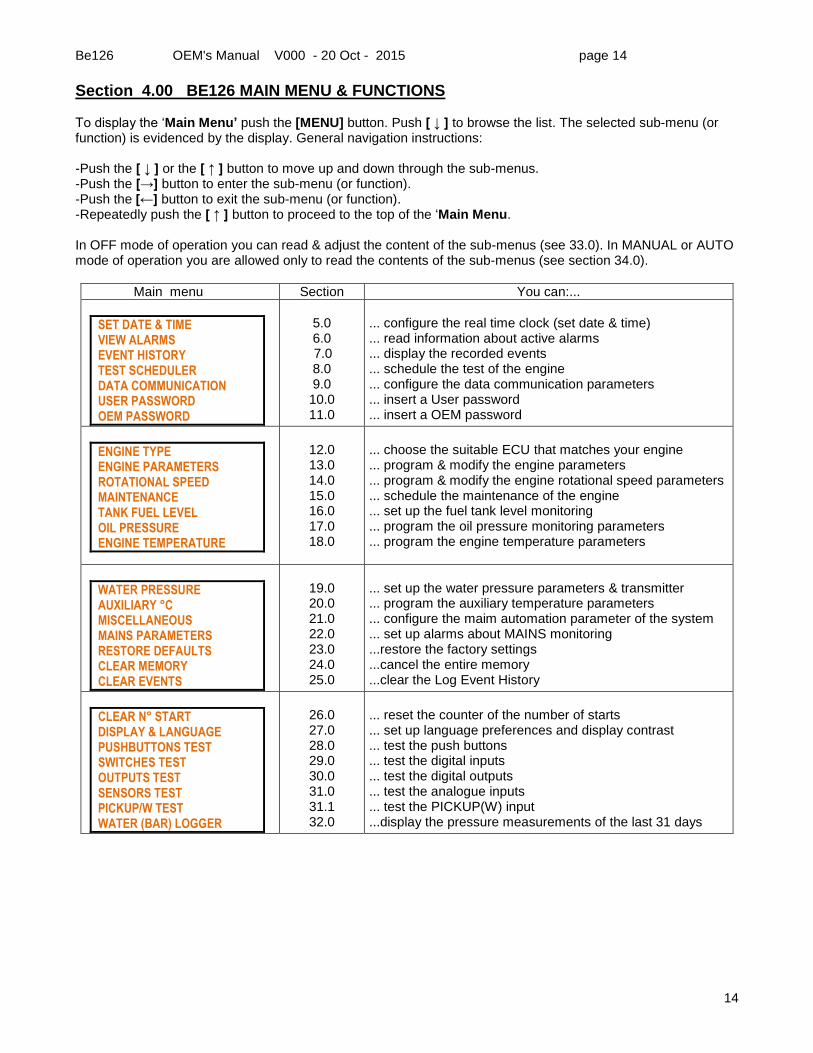
Section 4.00 BE126 MAIN MENU & FUNCTIONS To display the ‘Main Menu’ push the [MENU] button. Push [ ↓ ] to browse the list. The selected sub-menu (or function) is evidenced by the display. General navigation instructions: -Push the [ ↓ ] or the [ ↑ ] button to move up and down through the sub-menus. -Push the [→] button to enter the sub-menu (or function). -Push the [←] button to exit the sub-menu (or function). -Repeatedly push the [ ↑ ] button to proceed to the top of the ‘Main Menu. In OFF mode of operation you can read & adjust the content of the sub-menus (see 33.0). In MANUAL or AUTO mode of operation you are allowed only to read the contents of the sub-menus (see section 34.0).
Main menu Section You can:...
SET DATE & TIME VIEW ALARMS EVENT HISTORY TEST SCHEDULER DATA COMMUNICATION USER PASSWORD OEM PASSWORD
5.0 6.0
7.0 8.0 9.0 10.0 11.0
... configure the real time clock (set date & time) ... read information about active alarms ... display the recorded events ... schedule the test of the engine ... configure the data communication parameters ... insert a User password ... insert a OEM password
ENGINE TYPE ENGINE PARAMETERS ROTATIONAL SPEED MAINTENANCE TANK FUEL LEVEL OIL PRESSURE ENGINE TEMPERATURE
12.0 13.0 14.0 15.0 16.0 17.0 18.0
... choose the suitable ECU that matches your engine ... program & modify the engine parameters ... program & modify the engine rotational speed parameters ... schedule the maintenance of the engine ... set up the fuel tank level monitoring ... program the oil pressure monitoring parameters ... program the engine temperature parameters
WATER PRESSURE AUXILIARY °C MISCELLANEOUS MAINS PARAMETERS RESTORE DEFAULTS CLEAR MEMORY CLEAR EVENTS
19.0 20.0 21.0 22.0 23.0 24.0 25.0
... set up the water pressure parameters & transmitter ... program the auxiliary temperature parameters ... configure the maim automation parameter of the system ... set up alarms about MAINS monitoring ...restore the factory settings ...cancel the entire memory ...clear the Log Event History
CLEAR N° START DISPLAY & LANGUAGE PUSHBUTTONS TEST SWITCHES TEST OUTPUTS TEST SENSORS TEST PICKUP/W TEST WATER (BAR) LOGGER
26.0 27.0 28.0 29.0 30.0 31.0 31.1 32.0
... reset the counter of the number of starts ... set up language preferences and display contrast ... test the push buttons ... test the digital inputs ... test the digital outputs ... test the analogue inputs ... test the PICKUP(W) input ...display the pressure measurements of the last 31 days
Be126 OEM's Manual V000 - 20 Oct - 2015 page 15
15
Section 5.0 - SET DATE & TIME (REAL TIME CLOCK) Push the [MENU] button to open the Main Menu. The [SET DATE & TIME] menu is the first of the list. Push the [→] button to
open the real time clock page.
Display Instructions
TIME 00:00:00 DATE 01/01/00 FORMAT DD/MM/YY SAVE [→]
Use [ ↑ ] or [ ↓ ] to select a function. Push [→] to enter the numerical field. Push [ ↑ ] or [ ↓ ] to set a value. Push [←] to return. The item [00:00:00] (seconds) is always forced to zero. If you want to change the format, choose [FORMAT] and push [→]. Select the proper option by using [ ↑ ] or [ ↓ ]. Push [←] to return to the function.
If the option [DD/MM/YY] is suitable for your requirement, push [ ↓ ] to proceed. Select the [SAVE] item by using the [ ↓ ] arrow. When the Be126 backlights the [SAVE] item, push the [→] arrow to initiate the clock of Be126 at the correct local time (use an external clock reference) or push [←] to quit without affecting the clock.
Section 6.0 – VIEW ALARMS (ALARM MONITORING) This menu can contain up to 10 pages of active alarms tagged with date and time. This page, called ‘Alarm Page’, opens automatically in case of alarm(s), but you can open it at any time by selecting the sub menu [VIEW ALARMS]
from the Main Menu. A typical alarm page is indicated below:
To open the ‘Alarm Page’, in case of an alarm, push the [HOME] button.
ALARM: 1/10 LOW OIL PRESSURE SHUTDOWN 0,8 BAR DD/MM/YY HH:MM:SS
ALARM: 2/10 LOW OIL PRESSURE WARNING 2,8 BAR DD/MM/YY HH:MM:SS
Use [ ↑ ] or [ ↓ ] to browse additional alarm pages. The alarms are also recorded in the
Event History memory (see section 7.0). To exit the alarm page, push [HOME]: you open the ‘System Status Page’ (see 3.0). In case of alarm, the [HOME] button allow you to toggle between the ‘Alarm Page’ and
the ‘System Status Page’. To cancel the alarms, you are required to enter the OFF mode of operation (see 36.0). When you enter the ‘Alarm Page’ and there are not active alarms, the display indicates the message [NO ALARMS!].
Section 7.0 – EVENTS HISTORY (EVENTS LOG) This menu can contains up to 200 pages of events tagged with date and time. A typical page is indicated below. To access this sub-menu, push the [MENU] button to open the Main Menu. Repeatedly push the [ ↓ ] button until you reach the [EVENT HISTORY] menu. Push [→] to enter the sub-menu.
Event page description
EVENT: 1/200 START DEMAND ON
HH:MM:SS DD/MM/YY
EVENT: 2/200 AUTO MODE
HH:MM:SS DD/MM/YY
Use the [ ↑ ] or [ ↓ ] arrow to browse the pages. To exit the page, push the [HOME]
button: you open the ‘System Status Page’ (see section 3.0). The Be126 records up to 200 events. The display provides date & time information for warnings, shutdowns and other events.
Note: to remove the content of the pages you can use the [CLEAR EVENTS] command
(see section 25.0).
Be126 OEM's Manual V000 - 20 Oct - 2015 page 16
16
Section 8.0 - TEST SCHEDULER To program this sub-menu, push [OFF] to enter the OFF mode of operation. Push [MENU] to open the main menu list. Repeatedly push the [ ↓ ] button until you reach the [TEST SCHEDULER] menu. Push [→] to enter.
Display Description (see also section 2.4.4)
START STOP MO - -:- - - -:- - TU - -:- - - -:- - WE - -:- - - -:- -
You can set up the time to start & automatically stop the engine on specific days of the week. Before setting up the scheduler, you are required to set up the date and time of the internal clock (see 5.0). If you fail to set up the clock, the [CLOCK ERROR WARNING] alarm will take place (see 36.0).
Follow the instructions: Use [ ↑ ] or [ ↓ ] to select a day of the week. Push [→] to enter the START field. Use [→], [ ↑ ] and [ ↓ ] to set HH:MM. Push [→] to enter the STOP field. Use [→], [ ↑ ] and [ ↓ ] to set HH:MM. Repeatedly push [←] to return to the day selection. Do the same in case you want set up additional day of the week. Push [←] to exit.
The scheduler triggers a test only in AUTO mode of operation. Durint the TEST, the display will indicate the message TEST instead of AUTO. In case of NFPA /EN applications, take
care to program the automatic shut down accordingly (see2.4.4).
Section 9.0 - DATA COMMUNICATION To access this menu, see the instructions on section 4.0.
Display Description
MOD-BUS CB1 OFF MOD-BUS CB2 OFF
BE126 NODE 3 MODEM RESET OFF
This menu allows you to set up the MOD-BUS data communication for the battery chargers. Default settings provide ‘NO MOD-BUS’ battery charger. In NFPA/EN applications we recommend that you set MOD-BUS 1 & 2 to ‘ON’ and connect a Bernini Design MCB battery charger. ‘Battery Charger 1’ features the NODE 1. ‘Battery Charger 2’ features the NODE 2. Connect ‘Battery Charger 1’ to battery set ‘1’ & ‘Battery Charger 2’ to battery set ‘2’. Default MOD-BUS node for BE126 is ‘3’. The nodes 1 & 2 are reserved for the battery chargers. In case you enable a battery charger MOD-BUS, you are no longer allowed to setup a [BE126 NODE] to 1 or 2 for the BE126. The [MODEM RESET] option [ON] allows you to supply the modem via the JC-1 output. When the Be126 detects a failure in the modem, the Be126 shuts down the output for a few second providing a power on reset for the Modem.
Section 10.0 - USER PASSWORD To access this menu, see instructions on section 4.0.
Display Instructions for setting up a USER password
PASSWORD CLEAR PASSWORD
NEW PASSWORD BACK * * * * OK
[←] [→]
CLEAR PASSWORD
[←] YES NO [→]
The display will present the options [PASSWORD] (to insert a new password) and [CLEAR PASSWORD] (to cancel an existing password). Use [ ↑ ] or [ ↓ ] to select a function. Push [→] to enter the function.
Insert a password
a) Push [→] to select the first digit on the left. b) Push [ ↑ ] and [ ↓ ] to choose a number in between 1 to 9. c) Push [→] to move right to the second digit from the left.
d) Repeat step b) and step c) until you program the all 4 digits. d) Push [→] to confirm the password.
e) From now on, programming will be password protected. By using the OEM password you are not authorized to access the USER parameters (and vice versa).
Remove (clear) the password
a) To clear a password you are required to select the [CLEAR PASSWORD] function.
b) The display indicates the available options: YES ([←]) or NO ([→]).
c) The display will indicate the message [CLEAR PASSWORD DONE]. d) From now on, you will no longer need the User Password.
(*)Note: the password ‘0000’ is not allowed
If you have lost the password, see section 35.0 for additional help
Be126 OEM's Manual V000 - 20 Oct - 2015 page 17
17
Section 11.0 - OEM PASSWORD
To access this menu, push [OFF] to enter the OFF mode of operation. Push [MENU] to open the main menu list. Repeatedly push the [ ↓ ] button to select [OEM PASSWORD]. Push [→] to enter the Menu.
Display Instructions for OEM password
PASSWORD CLEAR PASSWORD
NEW PASSWORD BACK * * * * OK
[←] [→]
CLEAR PASSWORD
[←] YES NO [→]
The display will present the option [PASSWORD] (to insert a new password) and [CLEAR PASSWORD] (to cancel an existing password). Use [ ↑ ] or [ ↓ ] to select a function and push [→] to enter the function.
Insert a password
a) Push [→] to select the first digit on the left. b) Push [ ↑ ] and [ ↓ ] to choose a number in between 1 to 9. c) Push [→] to move right to the second digit from the left.
d) Repeat step b) and step c) until you program the all 4 digits. d) Push [→] to confirm the password.
e) From now on, programming will be password protected. Note that using the OEM password you are not authorized to access the USER parameters (and vice versa).
Remove (clear) a password
a) To clear a password you are required to select the [CLEAR PASSWORD] function.
b) The display indicates the available options: YES ([←]) or NO ([→])
c) The display will indicate the message [CLEAR PASSWORD DONE]. d) From now on, you will no longer need a password to program the Be126.
(*) Note: the password ‘0000’ is not allowed
If you have lost the password, see section 35.0 for additional help
Section 12.0 - ENGINE TYPE
Use [ ↑ ] or [ ↓ ] to select the [ENGINE TYPE] from the Main Menu (section 4.0). Push [→] to enter this submenu.
Engine type selection Instructions
ENGINE:
CONVENTIONAL UP( F4) –NEXT DOWN (F3) – PREVIUS LEFT (F1) – EXIT OR SAVE
SAVE?
[←] YES NO [→]
A) - Use the [ ↑ ] or [ ↓ ] to select the type of engine or to select the correct option for
your application.
B) - Push the [←](F1) to open the confirmation page.
C) - Push the [←](F1) to save the configuration (push [→](F2) to quit).
NOTE - After saving, we recommend that you remove the battery supply for a few seconds. When you reconnect the supply, check the initial page on the display: a welcome message should indicate the model or the option you saved in the memory. NOTE: the term [CONVENTIONAL ] stands for standard engine without ECU (in other words without CANbus).
Table 12.0 List of engine types (the list is subject to change without prior notice)
[ 7 ] Scania EMS2 [ 15 ] Detroit Diesel [ 23 ] Not used
[ 8 ] John Deere [ 16 ] Iveco Cursor [ 24 ] Not used
Be126 OEM's Manual V000 - 20 Oct - 2015 page 18
18
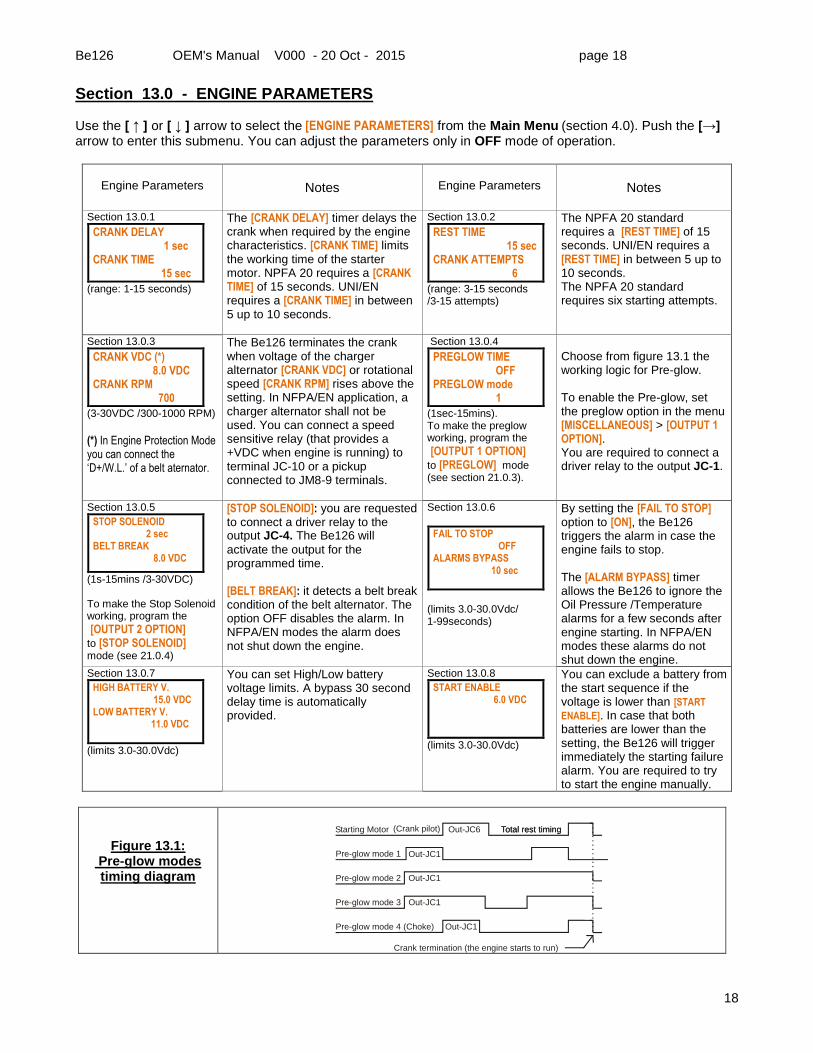
Section 13.0 - ENGINE PARAMETERS Use the [ ↑ ] or [ ↓ ] arrow to select the [ENGINE PARAMETERS] from the Main Menu (section 4.0). Push the [→] arrow to enter this submenu. You can adjust the parameters only in OFF mode of operation.
Engine Parameters
Notes
Engine Parameters
Notes
Section 13.0.1
CRANK DELAY 1 sec CRANK TIME 15 sec
(range: 1-15 seconds)
The [CRANK DELAY] timer delays the crank when required by the engine characteristics. [CRANK TIME] limits the working time of the starter motor. NPFA 20 requires a [CRANK TIME] of 15 seconds. UNI/EN requires a [CRANK TIME] in between 5 up to 10 seconds.
Section 13.0.2
REST TIME 15 sec CRANK ATTEMPTS 6
(range: 3-15 seconds /3-15 attempts)
The NPFA 20 standard requires a [REST TIME] of 15 seconds. UNI/EN requires a [REST TIME] in between 5 up to 10 seconds. The NPFA 20 standard requires six starting attempts.
Section 13.0.3
CRANK VDC (*) 8.0 VDC CRANK RPM 700
(3-30VDC /300-1000 RPM)
(*) In Engine Protection Mode you can connect the ‘D+/W.L.’ of a belt aternator.
The Be126 terminates the crank when voltage of the charger alternator [CRANK VDC] or rotational speed [CRANK RPM] rises above the setting. In NFPA/EN application, a charger alternator shall not be used. You can connect a speed sensitive relay (that provides a +VDC when engine is running) to terminal JC-10 or a pickup connected to JM8-9 terminals.
Section 13.0.4
PREGLOW TIME OFF PREGLOW mode 1
(1sec-15mins). To make the preglow working, program the
[OUTPUT 1 OPTION] to [PREGLOW] mode (see section 21.0.3).
Choose from figure 13.1 the working logic for Pre-glow. To enable the Pre-glow, set the preglow option in the menu [MISCELLANEOUS] > [OUTPUT 1 OPTION]. You are required to connect a driver relay to the output JC-1.
Section 13.0.5
STOP SOLENOID 2 sec BELT BREAK 8.0 VDC
(1s-15mins /3-30VDC) To make the Stop Solenoid working, program the
[OUTPUT 2 OPTION] to [STOP SOLENOID] mode (see 21.0.4)
[STOP SOLENOID]: you are requested to connect a driver relay to the output JC-4. The Be126 will
activate the output for the programmed time. [BELT BREAK]: it detects a belt break condition of the belt alternator. The option OFF disables the alarm. In NFPA/EN modes the alarm does not shut down the engine.
Section 13.0.6
FAIL TO STOP OFF ALARMS BYPASS 10 sec
(limits 3.0-30.0Vdc/ 1-99seconds)
By setting the [FAIL TO STOP] option to [ON], the Be126 triggers the alarm in case the engine fails to stop. The [ALARM BYPASS] timer allows the Be126 to ignore the Oil Pressure /Temperature alarms for a few seconds after engine starting. In NFPA/EN modes these alarms do not shut down the engine.
Section 13.0.7
HIGH BATTERY V. 15.0 VDC LOW BATTERY V. 11.0 VDC
(limits 3.0-30.0Vdc)
You can set High/Low battery voltage limits. A bypass 30 second delay time is automatically provided.
Section 13.0.8
START ENABLE 6.0 VDC
(limits 3.0-30.0Vdc)
You can exclude a battery from the start sequence if the voltage is lower than [START
ENABLE]. In case that both batteries are lower than the setting, the Be126 will trigger immediately the starting failure alarm. You are required to try to start the engine manually.
Figure 13.1: Pre-glow modes timing diagram
Starting Motor Total rest timing
Pre-glow mode 1
Pre-glow mode 2
Pre-glow mode 3
(Crank pilot) Out-JC6
Out-JC1
Out-JC1
Out-JC1
Out-JC1Pre-glow mode 4 (Choke)
Total rest timing
Crank termination (the engine starts to run)
Be126 OEM's Manual V000 - 20 Oct - 2015 page 19
19
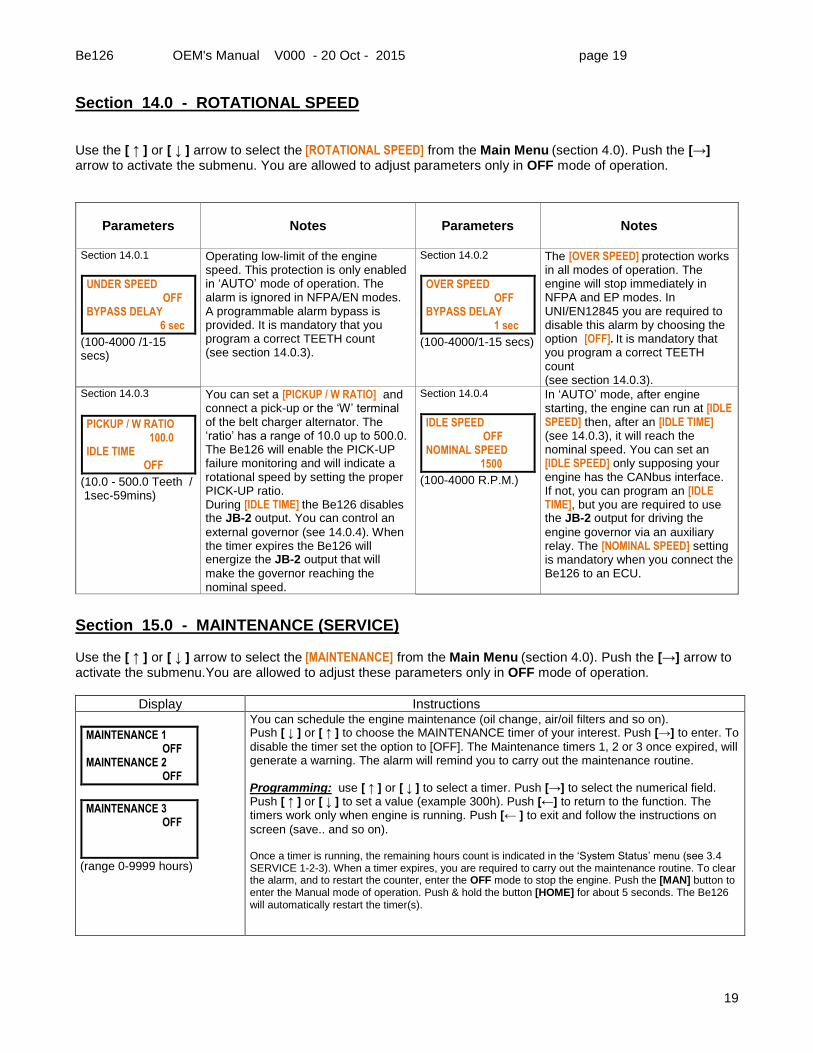
Section 14.0 - ROTATIONAL SPEED Use the [ ↑ ] or [ ↓ ] arrow to select the [ROTATIONAL SPEED] from the Main Menu (section 4.0). Push the [→] arrow to activate the submenu. You are allowed to adjust parameters only in OFF mode of operation.
Parameters
Notes
Parameters
Notes
Section 14.0.1
UNDER SPEED OFF BYPASS DELAY 6 sec
(100-4000 /1-15 secs)
Operating low-limit of the engine speed. This protection is only enabled in ‘AUTO’ mode of operation. The alarm is ignored in NFPA/EN modes. A programmable alarm bypass is provided. It is mandatory that you program a correct TEETH count (see section 14.0.3).
Section 14.0.2
OVER SPEED OFF BYPASS DELAY 1 sec
(100-4000/1-15 secs)
The [OVER SPEED] protection works in all modes of operation. The engine will stop immediately in NFPA and EP modes. In UNI/EN12845 you are required to disable this alarm by choosing the option [OFF]. It is mandatory that you program a correct TEETH count (see section 14.0.3).
Section 14.0.3
PICKUP / W RATIO 100.0 IDLE TIME OFF
(10.0 - 500.0 Teeth / 1sec-59mins)
You can set a [PICKUP / W RATIO] and connect a pick-up or the ‘W’ terminal of the belt charger alternator. The ‘ratio’ has a range of 10.0 up to 500.0. The Be126 will enable the PICK-UP failure monitoring and will indicate a rotational speed by setting the proper PICK-UP ratio. During [IDLE TIME] the Be126 disables the JB-2 output. You can control an
external governor (see 14.0.4). When the timer expires the Be126 will energize the JB-2 output that will
make the governor reaching the nominal speed.
Section 14.0.4
IDLE SPEED OFF NOMINAL SPEED 1500
(100-4000 R.P.M.)
In ‘AUTO’ mode, after engine starting, the engine can run at [IDLE SPEED] then, after an [IDLE TIME] (see 14.0.3), it will reach the nominal speed. You can set an [IDLE SPEED] only supposing your engine has the CANbus interface. If not, you can program an [IDLE TIME], but you are required to use the JB-2 output for driving the
engine governor via an auxiliary relay. The [NOMINAL SPEED] setting is mandatory when you connect the Be126 to an ECU.
Section 15.0 - MAINTENANCE (SERVICE) Use the [ ↑ ] or [ ↓ ] arrow to select the [MAINTENANCE] from the Main Menu (section 4.0). Push the [→] arrow to activate the submenu.You are allowed to adjust these parameters only in OFF mode of operation.
Display Instructions
MAINTENANCE 1 OFF MAINTENANCE 2 OFF
MAINTENANCE 3 OFF
(range 0-9999 hours)
You can schedule the engine maintenance (oil change, air/oil filters and so on). Push [ ↓ ] or [ ↑ ] to choose the MAINTENANCE timer of your interest. Push [→] to enter. To
disable the timer set the option to [OFF]. The Maintenance timers 1, 2 or 3 once expired, will generate a warning. The alarm will remind you to carry out the maintenance routine. Programming: use [ ↑ ] or [ ↓ ] to select a timer. Push [→] to select the numerical field. Push [ ↑ ] or [ ↓ ] to set a value (example 300h). Push [←] to return to the function. The timers work only when engine is running. Push [← ] to exit and follow the instructions on
screen (save.. and so on). Once a timer is running, the remaining hours count is indicated in the ‘System Status’ menu (see 3.4 SERVICE 1-2-3). When a timer expires, you are required to carry out the maintenance routine. To clear the alarm, and to restart the counter, enter the OFF mode to stop the engine. Push the [MAN] button to enter the Manual mode of operation. Push & hold the button [HOME] for about 5 seconds. The Be126 will automatically restart the timer(s).
Be126 OEM's Manual V000 - 20 Oct - 2015 page 20
20
Section 16.0 - TANK FUEL LEVEL (JM-5 INPUT) Use the [ ↑ ] or [ ↓ ] arrow to select the [TANK FUEL LEVEL] submenu from the Main Menu (section 4.0). Push the [→] button to open this submenu. You are allowed to adjust parameters only in OFF mode of operation.
(15s-99mins / 1-99%) NOTE: the Be126 will not shut down the engine in NFPA/EN modes of operation.
The Be126 triggers the [FUEL RESERVE WARNIING] alarm if you connect to a battery minus the JF-5 digital input. By programming a [BYPASS SWITCH] time, the engine will shut down after programmable time. During the [BYPASS SWITCH] timing the Be126 triggers the [FUEL RESERVE] warning. The option [OFF] will make the Be126 to provide a warning without shutting down the engine. The Be126 shuts down the engine if you program a [LOW % SHUTDOWN] limit. The Be126 provides, automatically, a 15 second bypass time delay. You are required to connect a resistive sensor to the JM-5 input.
Section 16.0.2
LOW % WARNING OFF HIGH % WARNING OFF
(limits 1-99%)
You can set Low and/or High fuel level alarms. The Be126 monitors the fuel level, providing a warning. The Be126 features a 15 second bypass alarm delay. You are required to connect a resistive sensor to the JM-5 input.
IMPORTANT NOTE ABOUT FUEL LEVEL MEASUREMENT
In order to make Be126 able to display the FUEL LEVEL
measurement, in addition to a level sensor connected to JM-5, you are required to set up at least one fuel level alarm for example
[LOW % WARNING] By keeping all alarms to [OFF], the display will not indicate a level
measurement.
Section 16.0.3
POINT 1 LEVEL 0% POINT 1 OHM 10 OHM
POINT 2 LEVEL 0% POINT 2 OHM 10 OHM
POINT 3 LEVEL 0% POINT 3 OHM 10 OHM
Fuel Level Sensor response curve. You can edit 6 points in between 0% up to 99% for the Fuel Level indication and 6 points for sensor resistance (0-1000 OHM). Factory programming complies with VDO /Continental fuel sensor. Fuel Level Sensor must be connected to JM-5. To display the
level measurement you are required to program a setting of ‘Low’ or ‘High’ level (see above).
Section 16.0.4
POINT 4 LEVEL 0% POINT 4 OHM 10 OHM
POINT 5 LEVEL 50% POINT 5 OHM 95 OHM
POINT 6 LEVEL 99% POINT 6 OHM 180 OHM
Fuel Level Sensor response curve. NOTE: If you set all fuel level alarms to OFF (as par default settings), the Be126 will ignore the input JM-5. You will not get
indication of fuel level. If you do not use an analog fuel level sensor, you can connect a level switch to the JF-5 input.
Be126 OEM's Manual V000 - 20 Oct - 2015 page 21
21
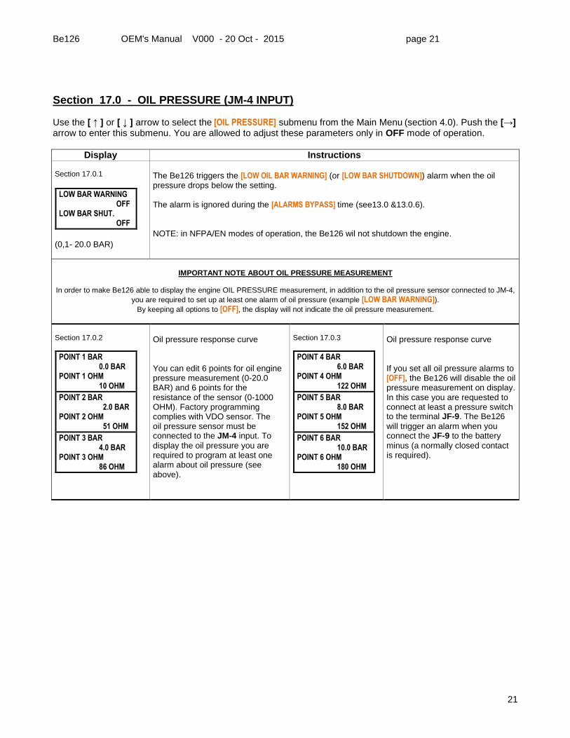
Section 17.0 - OIL PRESSURE (JM-4 INPUT) Use the [ ↑ ] or [ ↓ ] arrow to select the [OIL PRESSURE] submenu from the Main Menu (section 4.0). Push the [→] arrow to enter this submenu. You are allowed to adjust these parameters only in OFF mode of operation.
Display Instructions Section 17.0.1
LOW BAR WARNING OFF LOW BAR SHUT. OFF
(0,1- 20.0 BAR)
The Be126 triggers the [LOW OIL BAR WARNING] (or [LOW BAR SHUTDOWN]) alarm when the oil pressure drops below the setting. The alarm is ignored during the [ALARMS BYPASS] time (see13.0 &13.0.6). NOTE: in NFPA/EN modes of operation, the Be126 wil not shutdown the engine.
IMPORTANT NOTE ABOUT OIL PRESSURE MEASUREMENT
In order to make Be126 able to display the engine OIL PRESSURE measurement, in addition to the oil pressure sensor connected to JM-4,
you are required to set up at least one alarm of oil pressure (example [LOW BAR WARNING]). By keeping all options to [OFF], the display will not indicate the oil pressure measurement.
Section 17.0.2
POINT 1 BAR 0.0 BAR POINT 1 OHM 10 OHM
POINT 2 BAR 2.0 BAR POINT 2 OHM 51 OHM
POINT 3 BAR 4.0 BAR POINT 3 OHM 86 OHM
Oil pressure response curve
You can edit 6 points for oil engine pressure measurement (0-20.0 BAR) and 6 points for the resistance of the sensor (0-1000 OHM). Factory programming complies with VDO sensor. The oil pressure sensor must be connected to the JM-4 input. To
display the oil pressure you are required to program at least one alarm about oil pressure (see above).
Section 17.0.3
POINT 4 BAR 6.0 BAR POINT 4 OHM 122 OHM
POINT 5 BAR 8.0 BAR POINT 5 OHM 152 OHM
POINT 6 BAR 10.0 BAR POINT 6 OHM 180 OHM
Oil pressure response curve If you set all oil pressure alarms to [OFF], the Be126 will disable the oil pressure measurement on display. In this case you are requested to connect at least a pressure switch to the terminal JF-9. The Be126
will trigger an alarm when you connect the JF-9 to the battery
minus (a normally closed contact is required).
Be126 OEM's Manual V000 - 20 Oct - 2015 page 22
22
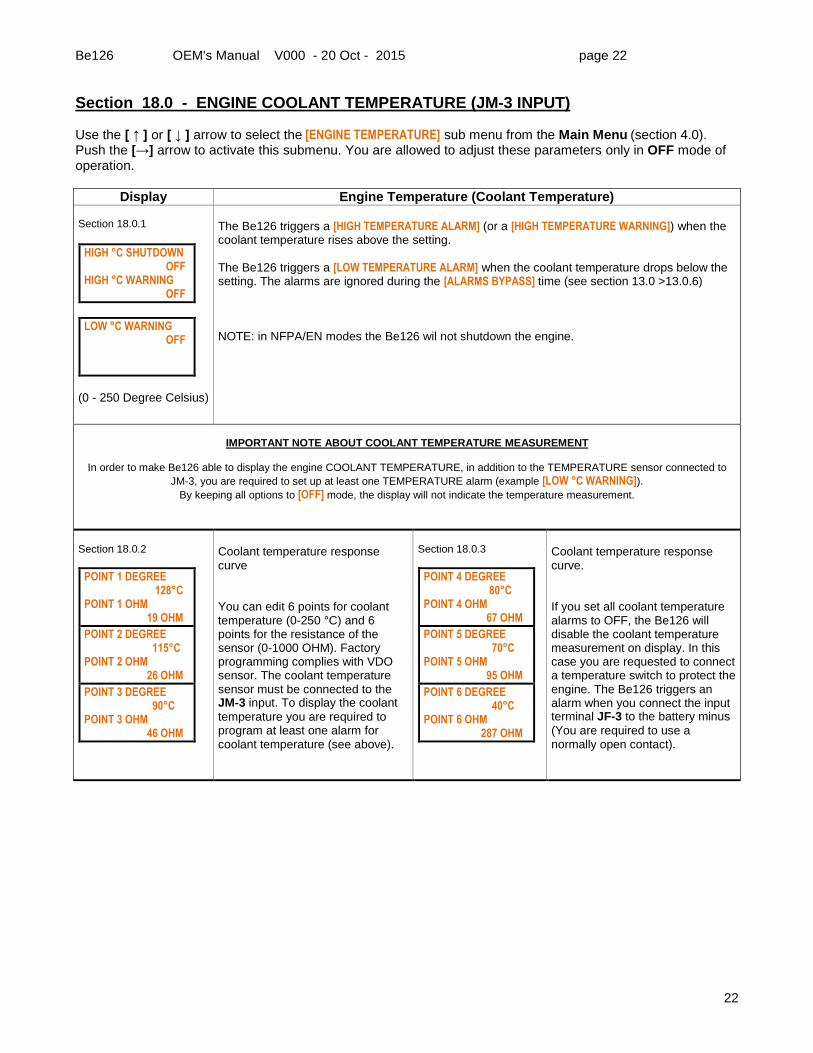
Section 18.0 - ENGINE COOLANT TEMPERATURE (JM-3 INPUT) Use the [ ↑ ] or [ ↓ ] arrow to select the [ENGINE TEMPERATURE] sub menu from the Main Menu (section 4.0). Push the [→] arrow to activate this submenu. You are allowed to adjust these parameters only in OFF mode of operation.
Display Engine Temperature (Coolant Temperature) Section 18.0.1
HIGH °C SHUTDOWN OFF HIGH °C WARNING OFF
LOW °C WARNING OFF
(0 - 250 Degree Celsius)
The Be126 triggers a [HIGH TEMPERATURE ALARM] (or a [HIGH TEMPERATURE WARNING]) when the coolant temperature rises above the setting. The Be126 triggers a [LOW TEMPERATURE ALARM] when the coolant temperature drops below the setting. The alarms are ignored during the [ALARMS BYPASS] time (see section 13.0 >13.0.6) NOTE: in NFPA/EN modes the Be126 wil not shutdown the engine.
IMPORTANT NOTE ABOUT COOLANT TEMPERATURE MEASUREMENT
In order to make Be126 able to display the engine COOLANT TEMPERATURE, in addition to the TEMPERATURE sensor connected to
JM-3, you are required to set up at least one TEMPERATURE alarm (example [LOW °C WARNING]). By keeping all options to [OFF] mode, the display will not indicate the temperature measurement.
Section 18.0.2
POINT 1 DEGREE 128°C POINT 1 OHM 19 OHM
POINT 2 DEGREE 115°C POINT 2 OHM 26 OHM
POINT 3 DEGREE 90°C POINT 3 OHM 46 OHM
Coolant temperature response curve
You can edit 6 points for coolant temperature (0-250 °C) and 6 points for the resistance of the sensor (0-1000 OHM). Factory programming complies with VDO sensor. The coolant temperature sensor must be connected to the JM-3 input. To display the coolant
temperature you are required to program at least one alarm for coolant temperature (see above).
Section 18.0.3
POINT 4 DEGREE 80°C POINT 4 OHM 67 OHM
POINT 5 DEGREE 70°C POINT 5 OHM 95 OHM
POINT 6 DEGREE 40°C POINT 6 OHM 287 OHM
Coolant temperature response curve. If you set all coolant temperature alarms to OFF, the Be126 will disable the coolant temperature measurement on display. In this case you are requested to connect a temperature switch to protect the engine. The Be126 triggers an alarm when you connect the input terminal JF-3 to the battery minus
(You are required to use a normally open contact).
Be126 OEM's Manual V000 - 20 Oct - 2015 page 23
23
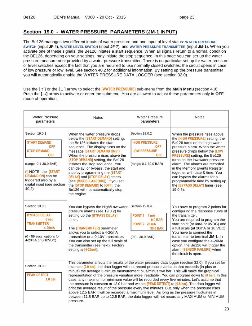
Section 19.0 - WATER PRESSURE PARAMETERS (JM-1 INPUT) The Be126 manages two different inputs of water pressure and one input of level status: WATER PRESSURE
SWITCH (input JF-4), WATER LEVEL SWITCH (input JF-7), and WATER PRESSURE TRANSMITTER (input JM-1). When you activate one of these signals, the Be126 initates a start sequence. When all signals return to a normal condition the BE126, depending on your settings, may initiate the stop sequence. In this page you can set up the water pressure measurement provided by a water pressure transmitter. There is no particular set up for water pressure or level switches except the fact that you are required to use normally closed switches: the circuit opens in case of low pressure or low level. See section 40.2 for additional information. By setting up the pressure transmitter you will automatically enable the WATER PRESSURE DATA LOGGER (see section 32.0). Use the [ ↑ ] or the [ ↓ ] arrow to select the [WATER PRESSURE] sub-menu from the Main Menu (section 4.0). Push the [→] arrow to activate or enter the submenu. You are allowed to adjust these parameters only in OFF mode of operation.
Water Pressure
parameters
Notes
Water Pressure
parameters
Notes
Section 19.0.1
START DEMAND OFF STOP DEMAND OFF
(range: 0.1-30.0 BAR)
(*) NOTE: the [START DEMAND ON] can be triggered also by a digital input (see section 40.2)
When the water pressure drops below the [START DEMAND] setting, the Be126 initiates the start sequence. The display turns on the message [START DEMAND ON](*). When the pressure rises above the [STOP DEMAND] setting, the Be126 initiates the stop sequence. You can delay, or bypass, the start and stop by programming the [START DELAY] and [STOP DELAY] timers (see [MISCELLANEOUS]). If you set the [STOP DEMAND] to [OFF], the Be126 will not automatically stop the engine.
Section 19.0.2
HIGH PRESSURE OFF LOW PRESSURE OFF
(range: 0.1-30.0 BAR)
When the pressure rises above the [HIGH PRESSURE] setting, the Be126 turns on the high water pressure alarm. When the water pressure drops below the [LOW PRESSURE] setting, the Be126 turns on the low water pressure alarm. The alarms are recorded in the Memory Events Register together with date & time. You can bypass the alarms for a programmable time by setting up the [BYPASS DELAY] timer (see 19.0.3).
Section 19.0.3
BYPASS DELAY 0 sec TRANSMITTER 4-20mA
(0 - 59 secs; options for 4-20mA or 0-10VDC)
You can bypass the High/Low water pressure alarms (see 19.0.2) by setting up the [BYPASS DELAY] timer. The [TRANSMITTER] parameter allows you to select a 4-20mA transmitter or a 0-10V transmitter. You can also set up the full scale of the transmitter (see next). Factory setting is [4-20mA].
Section 19.0.4
POINT 1 4 mA 0.0 BAR POINT 2 20 mA 30.0 BAR
(0.0 - 30.0 BAR)
You have to program 2 points for configuring the response curve of the transmitter. You are required to program the start point (at 4mA or 0VDC) and a full scale (at 20mA or 10 VDC). You have to connect the transmitter to terminal JM-1. In
case you configure the 4-20Ma option, the Be126 will trigger the alarm [SENSOR FAILURE] when the circuit is open.
Section 19.0.5
PEAK DETECT 1.0 bar
This parameter affects the results of the water pressure data logger (section 32.0). If you set for example [2.0 bar], the data logger will not record pressure variation that exceeds (in plus or minus) the average 5-minute measurement plus/minus two bar. This will make the graphical representation of the pressure variation more ‘readable’. You can program down to [0 bar]. In this case, any maximum or minimum value will be recorded every five minutes. Let’s assume that the pressure is constant at 12.0 bar and we set [PEAK DETECT] to [0.5 bar]. The data logger will print the average result of the pressure every five minutes. But, only when the pressure rises above 12.5 BAR it will be recorded a maximum level. As long as the pressure fluctuates in between 11.5 BAR up to 12.5 BAR, the data logger will not record any MAXIMUM or MINIMUM pressure.
Be126 OEM's Manual V000 - 20 Oct - 2015 page 24
24
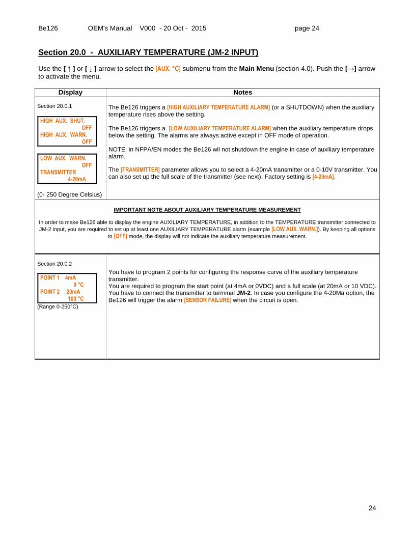
Section 20.0 - AUXILIARY TEMPERATURE (JM-2 INPUT) Use the [ ↑ ] or [ ↓ ] arrow to select the [AUX. °C] submenu from the Main Menu (section 4.0). Push the [→] arrow to activate the menu.
Display Notes Section 20.0.1
HIGH AUX. SHUT. OFF HIGH AUX. WARN. OFF
LOW AUX. WARN. OFF TRANSMITTER 4-20mA
(0- 250 Degree Celsius)
The Be126 triggers a [HIGH AUXILIARY TEMPERATURE ALARM] (or a SHUTDOWN) when the auxiliary temperature rises above the setting. The Be126 triggers a [LOW AUXILIARY TEMPERATURE ALARM] when the auxiliary temperature drops below the setting. The alarms are always active except in OFF mode of operation. NOTE: in NFPA/EN modes the Be126 wil not shutdown the engine in case of auxiliary temperature alarm.
The [TRANSMITTER] parameter allows you to select a 4-20mA transmitter or a 0-10V transmitter. You can also set up the full scale of the transmitter (see next). Factory setting is [4-20mA].
IMPORTANT NOTE ABOUT AUXILIARY TEMPERATURE MEASUREMENT
In order to make Be126 able to display the engine AUXILIARY TEMPERATURE, in addition to the TEMPERATURE transmitter connected to
JM-2 input, you are required to set up at least one AUXILIARY TEMPERATURE alarm (example [LOW AUX. WARN.]). By keeping all options
to [OFF] mode, the display will not indicate the auxiliary temperature measurement.
Section 20.0.2
POINT 1 4mA 0 °C POINT 2 20mA 100 °C
(Range 0-250°C)
You have to program 2 points for configuring the response curve of the auxiliary temperature transmitter. You are required to program the start point (at 4mA or 0VDC) and a full scale (at 20mA or 10 VDC). You have to connect the transmitter to terminal JM-2. In case you configure the 4-20Ma option, the
Be126 will trigger the alarm [SENSOR FAILURE] when the circuit is open.
Be126 OEM's Manual V000 - 20 Oct - 2015 page 25
25
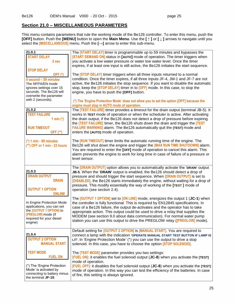
Section 21.0 – MISCELLANEOUS PARAMETERS This menu contains parameters that rule the working mode of the Be126 controller. To enter this menu, push the [OFF] button. Push the [MENU] button to open the Main Menu. Use the [ ↑ ] or [ ↓ ] arrows to navigate until you select the [MISCELLANEOUS] menu. Push the [→] arrow to enter this sub-menu.
21.0.1
START DELAY 2 sec STOP DELAY OFF (*)
0 second – 59 minutes The NFPA/EN mode ignores settings over 15 seconds. The Be126 will overwrite the parameter with 2 (seconds).
The [START DELAY] timer is programmable up to 59 minutes and bypasses the [START DEMAND ON] status in [AUTO] mode of operation. The timer triggers when you activate a low water pressure or water low water level. Once the timer expires, if at least one input is still active, the Be126 initiates the start sequence. The [STOP DELAY] timer triggers when all three inputs returned to a normal condition. Once the timer expires, if all three inputs JF-4, JM-1 and JF-7 are not active, the Be126 initiates the stop sequence. If you want to disable the automatic stop, keep the [STOP DELAY] timer in to [OFF] mode. In this case, to stop the engine, you have to push the [OFF] button. (*) The ‘Engine Protection Mode’ does not allow you to set the option [OFF] because the engine must stop in AUTO mode of operation.
21.0.2
TEST FAILURE 1 min (*) RUN TIMEOUT OFF (**)
(*) 1 min - 99 minutes (**) OFF or 1 min - 23 hours
The [TEST FAILURE] timer provides a timeout for the drain output (terminal JB-5). It works in TEST mode of operation or when the scheduler is active. After activating the drain output, if the Be126 does not detect a drop of pressure before expiring the [TEST FAILURE] timer, the Be126 shuts down the drain and trigger the [TEST FAILURE WARNING] alarm. The Be126 automatically quit the [TEST] mode and enters the [AUTO] mode of operation. The [RUN TIMEOUT] timer limits the automatic running time of the engine. The Be126 will shut down the engine and trigger the [MAX RUN TIME SHUTDOWN] alarm. You are required to enter the [OFF] mode of operation to cancel this alarm. This alarm prevents the engine to work for long time in case of failure of a pressure or level sensor.
21.0.3
DRAIN OUTPUT DRAIN OUTPUT 1 OPTION ONLINE
In Engine Protection Mode applications, you can set the [OUTPUT 1 OPTION] to [PREGLOW] mode (if required for your diesel engine)
The [DRAIN OUTPUT] option allows you to automatically activate the ‘DRAIN’ output JB-5. When the ‘DRAIN’ output is enabled, the Be126 should detect a drop of pressure and should trigger the start sequence. When [DRAIN OUTPUT] is set to [DISABLED], the Be126 starts immediately the engine, without waiting for a drop of pressure. This modify essentially the way of working of the [TEST ] mode of operation (see section 2.4). The [OUTPUT 1 OPTION] set to [ON LINE] mode, energizes the output 1 (JC-1) when the controller is fully functional. This is required by EN12845 specifications. In case of a Be126 failure, the output de-activates and the operator has to take appropriate action. This output could be used to drive a relay that supplies the MODEM (see section 9.0 about data communication). For normal water pump station you can use this output to drive the PREGLOW relay ([PREGLOW] mode).
21.0.4
OUTPUT 2 OPTION MANUAL START TEST MODE FUEL ON
(*) The ‘Engine Protection Mode’ is activated by connecting to battery minus the terminal JF-10.
Default setting for [OUTPUT 2 OPTION] is [MANUAL START]. You are required to connect a lamp with the indication 'OPERATE MANUAL START TEST BUTTON IF LAMP IS
LIT’. In ‘Engine Protection Mode’ (*) you can use the output to drive a stop solenoid. In this case, you have to choose the option [STOP SOLENOID]. The [TEST MODE] parameter provides you two settings: [FUEL ON]: it enables the fuel solenoid output (JC-8) when you activate the [TEST]
mode of operation. [FUEL OFF]: it disables the fuel solenoid output (JC-8) when you activate the [TEST]
mode of operation. In this way you can test the efficiency of the batteries. In case of fire, this setting is always ignored.
Be126 OEM's Manual V000 - 20 Oct - 2015 page 26
26
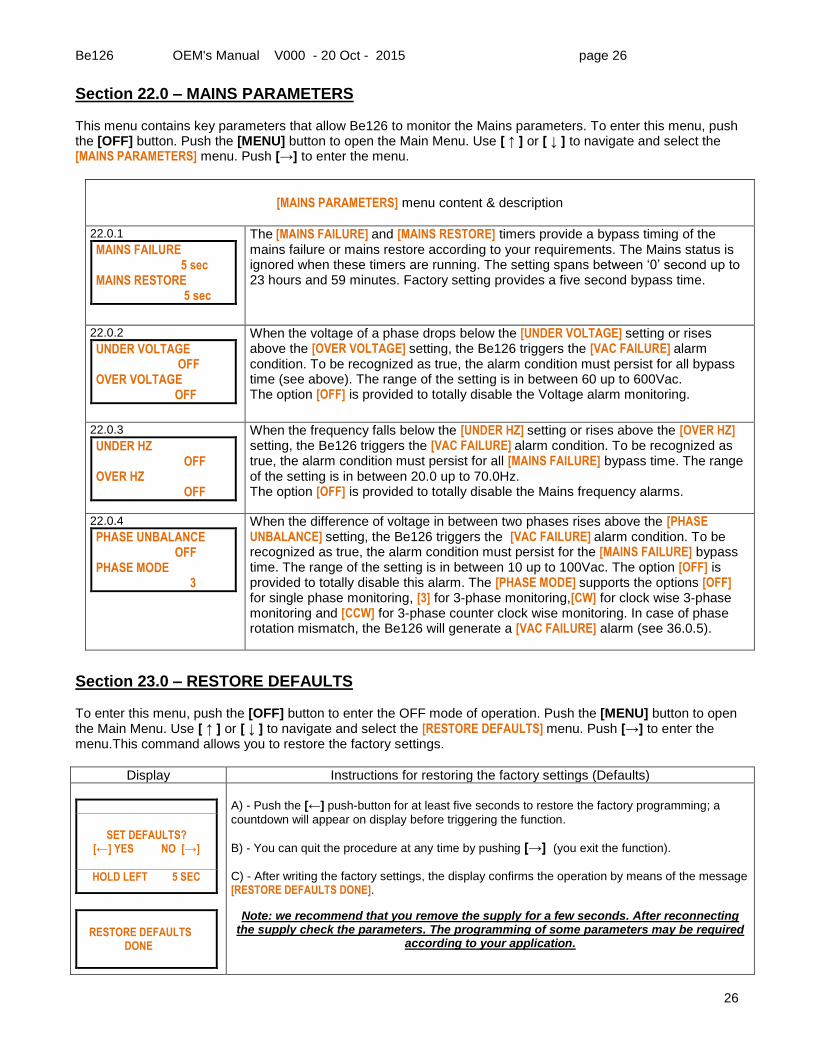
Section 22.0 – MAINS PARAMETERS This menu contains key parameters that allow Be126 to monitor the Mains parameters. To enter this menu, push the [OFF] button. Push the [MENU] button to open the Main Menu. Use [ ↑ ] or [ ↓ ] to navigate and select the [MAINS PARAMETERS] menu. Push [→] to enter the menu.
[MAINS PARAMETERS] menu content & description
22.0.1
MAINS FAILURE 5 sec MAINS RESTORE 5 sec
The [MAINS FAILURE] and [MAINS RESTORE] timers provide a bypass timing of the mains failure or mains restore according to your requirements. The Mains status is ignored when these timers are running. The setting spans between ‘0’ second up to 23 hours and 59 minutes. Factory setting provides a five second bypass time.
22.0.2
UNDER VOLTAGE OFF OVER VOLTAGE OFF
When the voltage of a phase drops below the [UNDER VOLTAGE] setting or rises above the [OVER VOLTAGE] setting, the Be126 triggers the [VAC FAILURE] alarm condition. To be recognized as true, the alarm condition must persist for all bypass time (see above). The range of the setting is in between 60 up to 600Vac. The option [OFF] is provided to totally disable the Voltage alarm monitoring.
22.0.3
UNDER HZ OFF OVER HZ OFF
When the frequency falls below the [UNDER HZ] setting or rises above the [OVER HZ] setting, the Be126 triggers the [VAC FAILURE] alarm condition. To be recognized as true, the alarm condition must persist for all [MAINS FAILURE] bypass time. The range of the setting is in between 20.0 up to 70.0Hz. The option [OFF] is provided to totally disable the Mains frequency alarms.
22.0.4
PHASE UNBALANCE OFF PHASE MODE 3
When the difference of voltage in between two phases rises above the [PHASE UNBALANCE] setting, the Be126 triggers the [VAC FAILURE] alarm condition. To be recognized as true, the alarm condition must persist for the [MAINS FAILURE] bypass time. The range of the setting is in between 10 up to 100Vac. The option [OFF] is provided to totally disable this alarm. The [PHASE MODE] supports the options [OFF] for single phase monitoring, [3] for 3-phase monitoring,[CW] for clock wise 3-phase monitoring and [CCW] for 3-phase counter clock wise monitoring. In case of phase rotation mismatch, the Be126 will generate a [VAC FAILURE] alarm (see 36.0.5).
Section 23.0 – RESTORE DEFAULTS To enter this menu, push the [OFF] button to enter the OFF mode of operation. Push the [MENU] button to open the Main Menu. Use [ ↑ ] or [ ↓ ] to navigate and select the [RESTORE DEFAULTS] menu. Push [→] to enter the menu.This command allows you to restore the factory settings.
Display Instructions for restoring the factory settings (Defaults)
SET DEFAULTS?
[←] YES NO [→]
HOLD LEFT 5 SEC
RESTORE DEFAULTS DONE
A) - Push the [←] push-button for at least five seconds to restore the factory programming; a
countdown will appear on display before triggering the function.
B) - You can quit the procedure at any time by pushing [→] (you exit the function).
C) - After writing the factory settings, the display confirms the operation by means of the message [RESTORE DEFAULTS DONE].
Note: we recommend that you remove the supply for a few seconds. After reconnecting the supply check the parameters. The programming of some parameters may be required
according to your application.
Be126 OEM's Manual V000 - 20 Oct - 2015 page 27
27
Section 24.0 – CLEAR THE MEMORY (select the [CLEAR MEMORY] sub-menu; see section 4.0)
Display Instructions for restoring the factory settings (Defaults)
CLEAR MEMORY?
[←] YES NO [→]
HOLD LEFT 5SEC
CLEAR MEMORY
DONE
A) - Push the [←] push-button for at least five seconds to cancel the memory; a count down will
appear on display before triggering the function.
B) - You can quit the procedure at any time by pushing [→] (you exit the function).
C) - After clearing the memory, the display confirms the operation via the message [CLEAR MEMORY DONE].
Note: we recommend that you remove the supply for a few seconds. After reconnecting the supply check the parameters. The programming of some parameters may be required
according to your application.
Section 25.0 – CLEAR THE EVENTS LOG (select the [CLEAR EVENTS] sub-menu; see section 4.0)
Display Instructions for clearing the memory event register.
CLEAR EVENTS?
[←] YES NO [→]
HOLD LEFT 5SEC
CLEAR EVENTS
DONE
A) - Push the [←] push-button for at least five seconds to cancel the log of all events: a count down
will appear on display before triggering the function.
B) - You can quit the procedure at any time by pushing [→] (you exit the function).
C) - After clearing the events, the display confirms the operation via the message [CLEAR EVENTS DONE].
Section 26.0 – CLEAR THE NUMBER OF STARTS (select the [CLEAR N°STARTS] sub-menu; see 4.0)
Display Instructions for resetting the two counters (#1 & #2) of the number of starts.
CLEAR N° STARTS?
[←] YES NO [→]
HOLD LEFT 5SEC
CLEAR N° STARTS
DONE
A) - Push the [←] push-button for at least five seconds to reset the number of starts counter; a
count down will appear on display before triggering the function.
B) - You can quit the procedure at any time by pushing [→] (you exit the function).
C) - After clearing the counters, the display confirms the operation via the message [CLEAR N° START DONE].
Be126 OEM's Manual V000 - 20 Oct - 2015 page 28
28
Section 27.0 - DISPLAY & LANGUAGE Push [MENU] to open the Main Menu. Repeatedly push the [ ↓ ] button until you select the [DISPLAY & LANGUAGE] menu. Push [→] to open the list of the availble options.
Display Instructions
LANGUAGE (*) ENGLISH CONTRAST 75%
A) - Use the [ ↑ ] or [ ↓ ] arrow to select a function. B) - Push the [→] arrow to enter the function. C) - Push [ ↑ ] or [ ↓ ] to choose the proper option or set a numerical value.
NOTE: contrast range is adjustable from 0 up to 100% in step of 5%. A setting of about 75% is suitable for all applications. (*) English, Italian, Spanish & French.
Section 28.0 - PUSH-BUTTONS TEST Push the [OFF] button to enter the [OFF] mode of operation. Push the [MENU] button to open the Main Menu. Use the [ ↑ ] or [ ↓ ] arrow to navigate and select the [PUSHBUTTONS TEST] menu. Push [→] to enter the menu. This menu displays the name of the push button that you activate.
Display Instructions
PUSH-BUTTONS TEST RIGHT DOWN START1 START2 TEST UP LEDS
Note: [OFF], [MAN] and [AUTO] push buttons are active all time (if you push [AUTO], the Be126 will enter the AUTO mode). To exit, push the [ACK] button.
WARNING: THIS PROCEDURE MUST BE CARRIED OUT BY QUALIFIED ONLY PERSONNEL. THE ENGINE MAY START OR YOU CAN INADVERTENTLY ACTIVATE SOME FUNCTIONS.
The purpose of this tool is to test the efficiency of the push buttons. Normally, without any push button pressed, the display must indicate the only message [PUSH-BUTTONS TEST]. On the left side you can see the position of the messages. Please note: if you push the [OFF] or [MAN] or [AUTO] button (supposing the button is working) you will get a change of mode of operation. In other words, these push buttons are always active. The [START1] & [START2] push-buttons trigger only a message on the display. But, using this troubleshooting tool, you can inadvertently start the engine of activate the crank motor.
Section 29.0 - SWITCHES TEST (DIGITAL INPUTS) To activate this sub-menu, push the [OFF] button to enter the [OFF] mode of operation. Push the [MENU] button to open the Main Menu. Use [ ↑ ] or [ ↓ ] to navigate and select the [SWITCHES TEST] sub-menu. Push [→] to enter the menu.This menu displays the name of the terminal that you activate.
When you connect a digital input to the battery minus, the display indicates the name of the connection. When all inputs are ‘open’ (not connected to battery minus), the display must
indicate only the message [SWITCHES TEST]. Activating one by one the inputs, the display
indicates the name of the connection. If you activate all inputs, the screen indicates all connections. If you activate one input and the display indicates two messages, there is an internal short-circuit; you have to return the controller for service.
Be126 OEM's Manual V000 - 20 Oct - 2015 page 29
29
Section 30.0 - OUTPUTS TEST (DIGITAL OUTPUTS)
To enter this menu, push the [OFF] button to enter the [OFF] mode of operation. Push the [MENU] button to open the Main Menu. Use [ ↑ ] or [ ↓ ] to navigate and select the [OUTPUTS TEST] menu. Push [→] to enter the menu.This menu displays the measurements made on the analog inputs.
Display Instructions
OUTPUTS TEST KEY UP/DOWN SELECTION KEY RIGHT OUTPUT ON
JC1 OUT 1
WARNING: THIS PROCEDURE MUST BE CARRIED OUT BY QUALIFIED ONLY PERSONNEL. THE ENGINE MAY START OR YOU CAN INADVERTENTLY ACTIVATE A WRONG OUTPUT
The output troubleshooting is menu driven. By using the [ ↑ ] or [ ↓ ] button, you select an output. You activate the output by pushing and holding the [→] button. The display indicates the terminal and the name of the connection. In case you use a lamp to test the output, we recommend that you not exceed 3W (either 12V or 24V).
Section 31.0 - SENSORS TEST (ANALOGUE INPUTS) To enter this menu, push the [OFF] button to enter the [OFF] mode of operation. Push the [MENU] button to open the Main Menu. Use [ ↑ ] or [ ↓ ] to navigate and select the [SENSORS TEST] menu. Push [→] to enter the menu.This menu displays the measurements made on the analog inputs.
Display Instructions
SENSORS TEST WATER PRES. 12.40 mA
AUX. TEMP. 8.5 mA
COOL. TEMP. 100 OHM
OIL PRESS. 220 OHM
FUEL LEVEL 220 OHM
Using this menu you can find out troubles of the analog inputs. You can connect a resistor of known value (in this example 100 OHM resistor) on the analog inputs. We recommend that you use a 100 up to 500 OHM resistor. The water pressure input and auxiliary temperatire input require a 4-20mA transmitter.
Description Input Range
WATER PRESSURE JM-1 8-12 mA
AUXILIARY TEMPERATURE JM-2 8-12mA
COOLANT TEMPERATURE JM-3 100-500 OHM
OIL PRESSURE JM-4 100-500 OHM
FUEL LEVEL JM-5 100-500 OHM
Section 31.1 - PICKUP / W TEST To enter this menu, push the [OFF] button to enter the [OFF] mode of operation. Push the [MENU] button to open the Main Menu. Use [ ↑ ] or [ ↓ ] to navigate and select the [PICKUP/W TEST] menu. Push [→] to enter the menu.This menu displays the measurements made on the analog inputs.
Display Instructions
PICKUP FREQUENCY L PICKUP RATIO 100.0
FREQUENCY 2804 HZ
SPEED 1682 RPM
Using this menu you can find out troubles on the pickup (or ‘W’) connection. The section 40.3.3 describes the electrical connections. Default setting for the teeth count is 100.0.
You can change it by setting the parameter [PICKUP/W RATIO] in the [ROTATIONAL SPEED] menu (see section 14.0). You can hold the pick in your hand. By movig it closer to
a ferrous surface you must see activity on the frequency measurement. By setting a
[PICKUP/W RATIO] to 60, the speed (RPM) and frequency (HZ) will have the same
indication. When you connect the ‘W’ do not forget to wire the jumper between terminals JM-7 & JM-8.
Be126 OEM's Manual V000 - 20 Oct - 2015 page 30
30
Section 32.0 - WATER PRESSURE DATA LOGGER The Be126 water pressure data logger is available all the time when you correctly set up the [WATER PRESSURE] menu. You are required to program a [START DEMAND], [HIGH PRESSURE] or a [LOW PRESSURE] alarm. The Be126 ‘System Status Page’ (see 3.0) displays the water pressure measurement provided by a pressure transmitter connected to the terminal JM-1. The Be126 automatically updates the [WATER (BAR) LOGGER] page every five minutes indicating average pressure measurements (P[AVG]), minimum pressure measurements (P[MIN]) and maximum pressure measurements (P[MAX]). The Be126 records as many as 26784 samples equivalent to 31 days of continuous recording. The display is organized in four columns that indicate time stamp, P[MIN], P[AVG]
and P[MAX]. On the [WATER (BAR) LOGGER] page you can: - browse the samples one by one (using the [SLOW UP/DOWN] mode). - browse the samples by days (using the [FAST UP/DOWN] mode). - locally download the data using the RS232 interface (you are required to enter the OFF mode of operation and to use our software for downloading the ‘PRESSURE.CSV’ file). - remotely downloads the data via the RS485 serial interface by using the Be126 software for remote monitoring. - set up a Low Pressure peak detect mode (the display shows only samples lower than P[AVG] - P[PK]) [*]. - set up a High Pressure peak detect mode (the display shows only samples higher than P[AVG] + P[PK]) [*]. To access the [WATER (BAR) LOGGER] page, push the [MENU] button. Repeatedly push the [ ↓ ] arrow to reach the last sub-menu of the Main Menu. When the display highlights the [WATER (BAR) LOGGER] menu, push the [→] arrow. The Be126 will open the water pressure data logger page. [*] Note: you can set up the P[PK] by programming the parameter [PEAK DETECT] (see the [WATER PRESSURE] menu, section 19.0)
A) - The first line of the display indicates the day, month and year. The column on the left indicates hours:minutes. Then, the display indicates the column of the minimum recorded values, the average recorded values and the maximum recorded values. If you set a [PEAK DETECT] filter, the display limits the indication of Min and Max values. Example: [PEAK DETECT] [0.5 BAR]. As you can see, on the left side, the Max value at 9:50 is missing and Min value is missing at 9:55. This is because no Max or Min values exceeded 8.0 BAR +/- 0.5 BAR have been detected. B) - Push the [→] button to choose the fast mode. In this way, by using the [ ↑ ] or [ ↓ ] arrows you can easily select a day of the last 31 recorded days. As a matter of fact in this way, by using the [ ↑ ] or [ ↓ ] arrows you change the days.
C) - Push the [→] button to choose the slow mode. In this way, by using the [ ↑ ] or [ ↓ ] arrows you can browse the 288 samples (one every five minutes) of a chosen
day.
Be126 OEM's Manual V000 - 20 Oct - 2015 page 31
31
Section 32.1 - DOWNLOADING WATER PRESSURE DATA LOGGER You can download the water pressure data logger data at any time in any mode of operation by using Be126 control and monitoring software. As an option, you can manually download the data by using a laptop. Follow the instructions.
- Push the [OFF] button to enter the OFF mode of operation. - Connect the USB plug to our RS232/USB module. - Push the [MENU] button to open the Main Menu. - Repeatedly push the [ ↓ ] arrow to reach the end of the Main Menu. - When the display highlights the [WATER (BAR) LOGGER] menu, push the [→] arrow to enter the menu; the Be126 opens the Water Pressure Data Log page. - Simultaneously push the [ ↓ ] and [→] arrows to trigger the data transfer - The display will inform you about downloading. It will take about two minutes. - After finishing, the display indicates the message [DONE] . - You can disconnect the cable and put the Be126 in auto mode of operation by pushing the [ AUTO ] button.
Be126 OEM's Manual V000 - 20 Oct - 2015 page 32
32
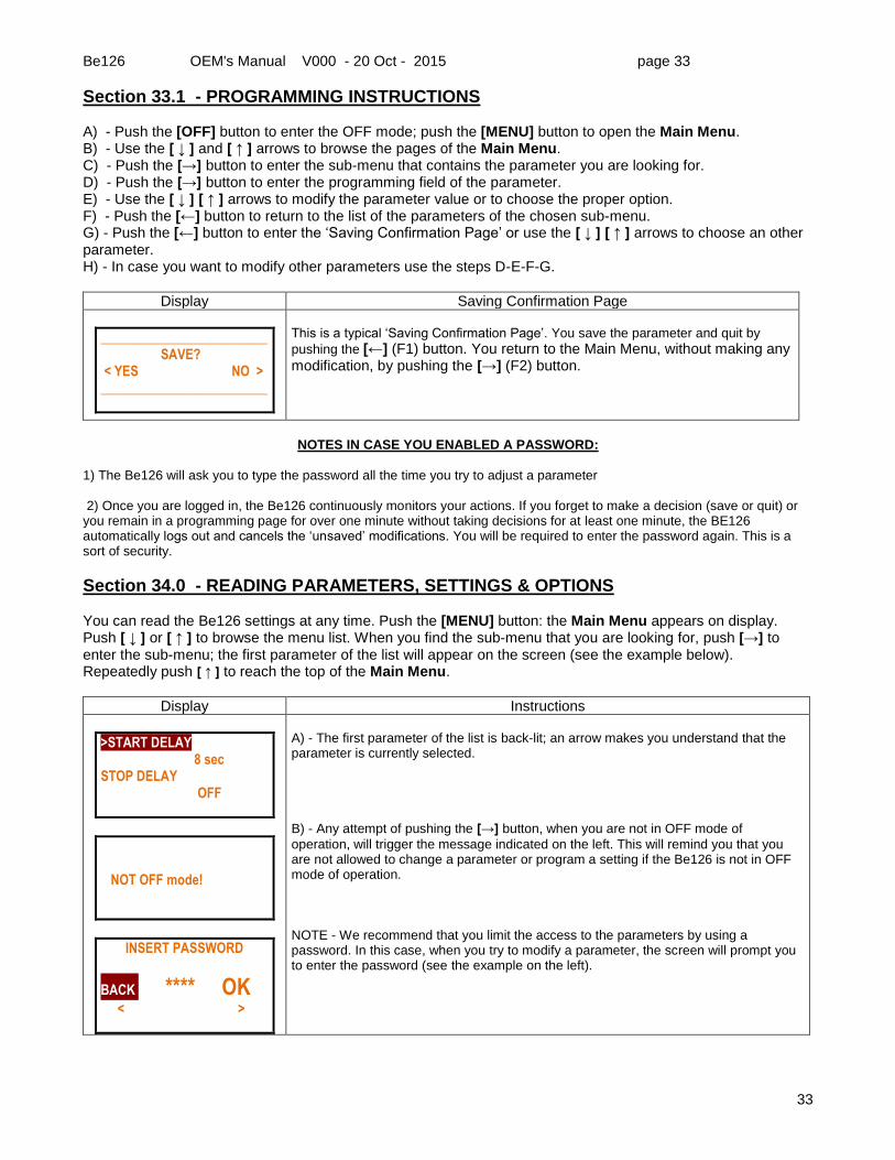
Section 33.0 - PROGRAMMING PARAMETERS, SETTINGS & OPTIONS You can program the Be126 in OFF mode of operation only. Push the [OFF] button to enter the OFF mode of operation. Push [MENU]: the Main Menu appears on display. Push [ ↓ ] on [ ↑ ] to browse the menu list. Repeatedly push [ ↑ ] to reach the top of the Main Menu. When you find the sub-menu that you are looking for, push [→] to enter the sub-menu; the first parameter of the list will appear on the screen (see the example below).
Display Instructions
>START DELAY 2 sec STOP DELAY OFF
START DELAY 8 sec . STOP DELAY OFF
.
>START DELAY 8 sec STOP DELAY OFF
_________________________ SAVE? < YES NO > _________________________
A) - The first parameter of the list is back-lit and an arrow notice you that the parameter is currently selected. B) - Push the [→] button to enter the parameter programming field; the setting of the parameter is back-lit. Push [ ↓ ] or [ ↑ ] to modify the parameter as requested by you.
C) - Push the [←] button to return. You can push the [ ↓ ] button to choose an other parameter or push again the [←] button to exit programming.
D) Before quitting, the Be126 asks for a confirmation. Push the [←] to quit & save the modification or push [→] to quit without saving the modification.
NOTE: you have 60 seconds to make a decision. After one minute, the Be126
automatically quit the programming without saving the setting.
We recommend that you limit the access to programming by using passwords. The USER password (see section 10.0) limits the access to the following menus & parameters
[SET DATE & TIME] [TEST SCHEDULER] [DISPLAY & LANGUAGE]
The OEM password has priority over USER password. In other words, using an OEM password you can pay access to a ‘USER’ parameters.
Be126 OEM's Manual V000 - 20 Oct - 2015 page 33
33
Section 33.1 - PROGRAMMING INSTRUCTIONS A) - Push the [OFF] button to enter the OFF mode; push the [MENU] button to open the Main Menu. B) - Use the [ ↓ ] and [ ↑ ] arrows to browse the pages of the Main Menu. C) - Push the [→] button to enter the sub-menu that contains the parameter you are looking for. D) - Push the [→] button to enter the programming field of the parameter. E) - Use the [ ↓ ] [ ↑ ] arrows to modify the parameter value or to choose the proper option. F) - Push the [←] button to return to the list of the parameters of the chosen sub-menu. G) - Push the [←] button to enter the ‘Saving Confirmation Page’ or use the [ ↓ ] [ ↑ ] arrows to choose an other parameter. H) - In case you want to modify other parameters use the steps D-E-F-G.
Display Saving Confirmation Page
_________________________ SAVE? < YES NO > _________________________
This is a typical ‘Saving Confirmation Page’. You save the parameter and quit by
pushing the [←] (F1) button. You return to the Main Menu, without making any modification, by pushing the [→] (F2) button.
NOTES IN CASE YOU ENABLED A PASSWORD:
1) The Be126 will ask you to type the password all the time you try to adjust a parameter
2) Once you are logged in, the Be126 continuously monitors your actions. If you forget to make a decision (save or quit) or you remain in a programming page for over one minute without taking decisions for at least one minute, the BE126 automatically logs out and cancels the ‘unsaved’ modifications. You will be required to enter the password again. This is a sort of security.
Section 34.0 - READING PARAMETERS, SETTINGS & OPTIONS You can read the Be126 settings at any time. Push the [MENU] button: the Main Menu appears on display. Push [ ↓ ] or [ ↑ ] to browse the menu list. When you find the sub-menu that you are looking for, push [→] to enter the sub-menu; the first parameter of the list will appear on the screen (see the example below). Repeatedly push [ ↑ ] to reach the top of the Main Menu.
Display Instructions
>START DELAY 8 sec STOP DELAY OFF
. NOT OFF mode!
INSERT PASSWORD
BACK **** OK
< >
A) - The first parameter of the list is back-lit; an arrow makes you understand that the parameter is currently selected. B) - Any attempt of pushing the [→] button, when you are not in OFF mode of
operation, will trigger the message indicated on the left. This will remind you that you are not allowed to change a parameter or program a setting if the Be126 is not in OFF mode of operation. NOTE - We recommend that you limit the access to the parameters by using a password. In this case, when you try to modify a parameter, the screen will prompt you to enter the password (see the example on the left).
Be126 OEM's Manual V000 - 20 Oct - 2015 page 34
34
Section 35.0 - RECOVERING A LOST PASSWORD In case you inadvertently lost the password, you can contact Bernini Design. You will be asked for some details & key information. Bernini Design will provide an 'alternative' password in order that you can retrieve your password. Once in the system you can change your password (User or/and OEM)
Section 36.0 - ALARMS WARNINGS SHUTDOWNS The Be126 features: A) - LED (Light Emitting Diode) to indicate alarms or shutdowns. B) - An alarm output committed to drive audible signals. C) - Descriptive messages, provided on graphic display about alarms with date & time. D) - Event history memory able to record 200 alarms and events. E) - An [HOME] push-button (°) to silence the audible signal and an [OFF] push button. (°) The [HOME] push-button is automatically disabled in NFPA/EN12845 mode of operation. You can still use this button for other purposes (display navigation for example).
Instructions in case of alarm(s):
1) Look at the front panel and take note about LED indicators and message(s) on the display. 2) Push the [HOME] push-button to silence the horn. Push the [OFF] push-button to cancel the alarm. 3) Consult the following sections for further information and remove the cause of the alarm.
The list of the alarms is indicated below on the left side. Additional information is provided on the right side. Shutdowns are serious alarms and will stop the engine; warnings and pre-alarms will allow the engine to run.
In NPFA mode only over-speed alarm is allowed to shutdown the engine.
36.0.1 Clock and Memory alarms
CLOCK ERROR WARNING
Real time clock failure or wrong programming of it. This alarm takes place in case you failed to program the Real Time Clock before programming the Scheduler (section 8.0). Always program the RTC first, then program the scheduler (section 5.0).
PARAMETER ERROR Error in a parameter. Try to re-program the parameter correctly (section 33.1). Check the upper or lower limit and verify the allowed options for it. You can remove the supply for a minute; then reconnect the supply. If the problem persists, you are required to return the controller for assistance.
CAN BUS ERROR WARNING
Failure of the Canbus communication. Check the wiring or the CAN bus settings for the ECU fitted on the engine (section 12.0).
RED LAMP SHUT WARNING
Engine failure detected by the ECU. Consult the user manual of the engine. This alarm does not shut down the engine but, it reminds you that a severe damage may occur to the engine. Consult the engine manufacturer if the problem persists.
MOD-BUS TIME OUT 1 MOD-BUS TIME OUT 2
Failure of the MOD-BUS communication. Check the wiring & MOD-BUS settings (section 9.0) of the ‘Battery charger 1’ & ‘Battery charger 2’.
BE126 FAILURE It indicates a memory error or a severe damage of the Be126 controller. You can try to disconnect the DC supply for a while. If the problem persists, you are required to return the controller to Bernini Design for assistance.
BE126 FAILURE
BE126 FAILURE
Be126 OEM's Manual V000 - 20 Oct - 2015 page 35
35
36.0.2 Battery & Battery Charger alarms
BATTERY CHARGER 1 ALARM (FAILURE)
These alarms are sent to Be126 via MOD-BUS from the battery chargers. It is about a general failure of the battery charger. These alarms energize also when you connect the alarm inputs JF-1 or JF-2 to the common battery minus. These inputs are used in case your battery chargers do not support a MOD-BUS communication, but they feature a dry contact alarm output relay. In case of alarm, check the fuses fitted on the battery chargers.
BATTERY CHARGER 2 ALARM (FAILURE)
LOW BATTERY 1 WARNING
These are, general purpose adjustable, alarms about ‘Battery 1’ & ‘Battery 2’. You can set a ‘low limit’ and a ‘high limit’ for each battery. An alarm bypass of about 15 seconds is automatically provided (see ‘Engine Parameter’ section 13.0). HIGH BATTERY 1
WARNING
LOW BATTERY 2 WARNING
HIGH BATTERY 2 WARNING
36.0.3 Emergency Input
EMERGENCY INPUT SHUTDOWN
This alarm triggers when you connect to battery minus the terminal JF-8. This alarms shuts down the engine immediately. This input shall not be used in an a NFPA 20 or EN12845 compliant system.
36.0.4 Miscellaneous engine alarms
PICK UP FAILURE
This alarm triggers when the detected speed is lower than CRANK-RPM (rotational speed crank termination) setting. The Be126 provides a 20 second alarm bypass. You are required to correctly set-up the speed parameters in the [ROTATIONAL SPEED] settings (section 14.0).
OVER SPEED SHUTDOWN XXXXRPM
Engine rotational over speed shutdown. You can program the limit and a bypass alarm time. (section 14.0)
UNDER SPEED SHUTDOWN (ALARM) XXXXRPM
Engine rotational under speed shutdown. You can program the limit and a bypass alarm time. In NFPA/EN applications, the alarm does not shut down the engine (section 14.0).
START 1 FAILURE WARNING
This warning takes place when a start attempt fails to start the engine. This provides important information in case you have problems in starting the engine. The Be126 will continuously try to start the engine until the programmed maximum numbers of attempts will be reached (section 13.0).
START 2 FAILURE WARNING
FAIL TO START SHUTDOWN (ALARM)
Fail to start shutdown. The BE126 stops any further starting attempt. You are required to enter the OFF mode of operation to clear the alarm. In case of fire, try to start the engine by using the [START 1] or [START 2] push-buttons.
FAIL TO STOP SHUTDOWN (ALARM)
This alarm triggers if, after a stop sequence, the Be126 detects an ‘Engine Running Status’. You are required to investigate the problem. You can disable the alarm by setting the option [OFF] into [FAIL TO STOP] parameter (see section 13.0 & 13.0.6).
BELT BREAK SHUTDOWN (ALARM)
Engine belt break (or belt driven charger failure) shut down. You can disable the alarm by setting the option 'OFF' into [BELT BREAK] parameter. In NFPA/EN modes, the alarm is ignored (see section 13.0 & 13.0.5).
UNEXPECTED STOP WARNING
This alarm triggers in case the engine stops by its own for unknown cause. You are required to investigate the problem and eventually restart the engine.
TEST FAILURE WARNING
There are three basic sources for this alarm: the engine fails to carry out a complete automatic test, the drain valve failed to work or, the pressure sensor failed to provide a start command to Be126. You are required to investigate the source and to repeat a manual test of the automatic system. To set-up correctly the ‘TEST’ parameters consult the section 21.0.
Be126 OEM's Manual V000 - 20 Oct - 2015 page 36
36
36.0.5 Mains alarms
VAC FAILURE This alarm triggers when a parameter of the mains (voltage, frequency, pahe sequence or
other) is no longer within the admitted limit. See section 22.0.
36.0.6 Temperature alarms (NOTE engine will not shut down in NFPA/EN mode)
LOW COOLANT °C WARNING XXX°C HIGH COOLANT °C WARNING XXX°C HIGH COOLANT °C SHUTDOWN XXX°C
You can set a low or/and high temperature limits for the engine coolant. The alarms are ignored during Alarms-Bypass timing. Coolant temperature information is provided by CAN bus or by a sensor connected to input JM-3. The ‘XXX’ notation stands for the temperature alarm recorded in the moment that the alarm triggered.
COOLANT SENDER OPEN
It indicates the failure of the temperature sensor connected to JM-3. It triggers when the measured resistance is over 2000 Ohm.
TEMPERATURE SW. SHUTDOWN (ALARM)
The high temperature shutdown alarm is triggered by a temperature switch. The switch must close the contact in case of high temperature. You are required to use the JF-3 input. The alarm is ignored during the [ALARM-BYPASS] time (see section 13.0).
LOW AUX °C WARNING HIGH AUX °C WARNING HIGH AUX °C SHUTDOWN
You can set an auxiliary temperature warning and / or a shutdown. You are required to connect a temperatire transmitter to input JM-2. The alarm is always active except in OFF mode of operation. You can monitor the ambient temperature or other critical part of the system. See section 20.0 about the [AUXILIARY °C] sub-menu.
AUX.°C SENDER OPEN
It indicates the failure of the temperature transmitter connected to JM-2 (e.g. open circuit).
36.0.7 Fuel Level alarms (NOTE engine will not shut down in NFPA/EN mode)
FUEL RESERVE WARNING
Fuel switch alarm monitoring (input JF-5). The Be126 monitors the fuel level in the tank via a level switch. The default setting provides a warning only, but by programming the [BYPASS SWITCH] timer you will allow the Be126 to shut down the engine after a programmable time. The alarm [FUEL RESERVE WARNING] energizes when the timer is running. Once expired, the Be126 will trigger the [FUEL RESERVE SHUTDOWN] alarm. (see section 16.0 about [TANK FUEL LEVEL] sub-menu).
FUEL RESERVE SHUTDOWN
LOW FUEL WARNING XX%
This alarm warns you about low fuel level in the tank (see section 16.0). The measurement is taken from the analog input JM-5.
HIGH FUEL WARNING XX%
This alarm warns you about high fuel level in the tank (see section 16.0). The measurement is taken from the analog input JM-5.
TANK EMPTY SHUTDOWN
The Be126 triggers this alarm when there is no fuel for the engine. Be126 shuts down the engine to prevent problems in the fuel circuits. This alarm is controlled by the parameter [LOW % SHUTDOWN] programmed in the [TANK FUEL LEVEL] sub-menu (see 16.0). The measurement is taken from the analog input JM-5.
FUEL SENDER OPEN
Failure of the fuel sensor connected to the input JM-5. The Be126 triggers an alarm when the resistance is over 2000 OHM.
Be126 OEM's Manual V000 - 20 Oct - 2015 page 37
37
36.0.8 Oil Pressure alarms (NOTE engine will not shut down in NFPA/EN mode)
LOW OIL PRESSURE SHUTDOWN (ALARM)
The alarm is ignored during [ALARMS BYPASS] timing. To enable this alarm, you are required to connect a ‘normally closed’ oil pressure switch to digital input JF-9. The Be126 does not shut
down the engine in NFPA/EN12845 mode. The alarm triggers when the pressure switch closes the contact.
LOW OIL BAR WARNING XX.X BAR
The Be126 indicates the oil pressure via CANbus or via a sensor connected to the JM-4
analog input. The Be126 displays the value recorded when the alarm triggered. To adjust the settings about low oil pressure follow the instructions in section 17.0. The Be126 triggers the ‘pressure sender open’ alarm when the resistance measured on the input is over 2000OHM.
LOW OIL BAR SHUTDOWN (ALARM) XX.X BAR
PRESSURE SENDER OPEN
36.0.9 Maintenance alarms (see section15.0)
SERVICE 1 WARNING
Service1 (2 or 3) provides a warning after timeout. To cancel the alarm follow the instructions: - push the [OFF] button to enter the ‘OFF’ mode of operation. - when the engine is totally stopped, push the [MAN] button to enter the ‘Manual’ mode. - push and hold the [HOME] button for at least five to 10 seconds. - the Be126 will automatically reload and restart the SERVICE TIMER.
SERVICE 2 WARNING
SERVICE 3 WARNING
MAX RUNTIME SHUTDOWN
Time expired. This timer allows the engine to run a limited number of continuous hours. To restart the engine and to cancel the alarm, you are required to enter the OFF mode of operation.
Section 37.0 - DETECT ENGINE RUNNING USING BELT ALTERNATOR When engine is fitted with a belt driven charger alternator (not the case of a fire pump application), the Be126 terminates the crank when voltage measured on the D+/W.L. terminal rises above the [CRANK VDC] setting. When the engine starts running, the voltage of the D+/WL increases. The point to terminate the crank is in between 6V to 10V. Default setting for [CRANK VDC] (section 13.0 & 13.0.3) is 8.0V. For 24V batteries, we recommend that you set the threshold of about 16V.
we recommend that you follow these instructions:
- Disconnect the fuel solenoid (the engine will not start). Push [MAN] to enter the manual mode of operation. - Push and hold the [START 1] (or [START 1]) button to crank the engine - Repeteadly push the [ ↓ ] button to reach the last page (see 3.5); the display indicates the [CHARGE.ALT.V]
- While cranking the engine, read on the display the [CHARGE.ALT.V]; it should be lower than [CRANK VDC] setting. - Make sure that Be126 does not terminate the crank while you hold the start (do not hold it for more than 20 secs). - Reconnect the fuel solenoid, and start the engine in MAN mode. - After teminating the crank, the display indicates the message ENGINE RUNNING and the green LED turns on - Repeteadly push the [ ↓ ] button to reach the last page (see 3.5); the display indicates the [CHARGE.ALT.V]
- When the engine is running, the voltage measurement should be closer to the battery voltage indication (14-15V).
Section 37.1 - NFPA20 / EN 12845 DETECT ENGINE RUNNING NFPA 20 & EN 12845 DO NOT ALLOW CRANK TERMINATION PROVIDED BY A BELT ALTERNATOR. YOU ARE REQUIRED TO USE A PICKUP OR A ROTATIONAL SPEED RELAY.
You are required to connect the pickup to terminals JM8-9-10. Section14.0 informs you about the mandatory settings. As alternative option, connect a rotational speed relay to terminal JC-10. The relay output must deliver a true engine running signal consisting of a stable dc voltage over 10Vdc when the engine is running and lower than four Vdc when engine is not running. You can adapt, if necessary, the input by programming the parameter [CRANK VDC] (see 13.0 & 13.0.3).
Be126 OEM's Manual V000 - 20 Oct - 2015 page 38
38
Section 38.0 - GENERAL SPECIFICATIONS Supply Voltage: 5.5Vdc to 36Vdc, 10-150mA max. Fuse: internal 300mA electronic. Reverse polarity: -36Vdc
Supply Voltage Surge Protection: 100Vdc /500 Amps (8/20 microseconds). Absorption capacity: 8 Joule max
Cranking Dropout: Be126 survives 0V for a half-second (initial voltage before the dropout: 12Vdc).
Dimensions: 250mm X 185mm X 67,5mm. Panel Size Cut-out: 239mm X 171mm. Ingress Protection: IP62
Operating Temperature Range: -30 deg. C up to +70 deg. C. Humidity Range: 5% up to 95% non-condensing.
Weight: 550 grams. General design: ECC 89/336, 89/392, 73/23, 93/68, IEC 68-2-6. Certification: CE
Static Outputs Characteristics: negative logic with 150mA output current, short circuit proof.
Generator Voltage: nominal voltage 70 Vac up to 600Vac (Ph-Ph) 347Vac (Ph-N). Over voltage: 4KVac Ph-Ph.
CAN Port: fully isolated. 250Kb/second. Internal 120 Ohm impedance available for connection. Supports SAE1939 protocol.
RS485 Port: support MOD-BUS Protocol and drives 1000 Metres twisted cable, ESD 2KV & drives up to 127 nodes.
Section 39.0 - SOFTWARE UPGRADES & REVISIONS
Firmware Versions
Date Description
0.00 Nov.2014 First Release (demo version)
5.00 Sept 2015 V500 (full production version)
Be126 OEM's Manual V000 - 20 Oct - 2015 page 39
39
Section 40.0 - TERMINAL DESCRIPTION (1 OF 4)
!! WARNING !! ANY INTERRUPTION OF THE PROTECTIVE GROUND OR DISCONNECTION OF THE PROTECTIVE EARTH IS LIKELY TO MAKE THE Be126 DANGEROUS
MAINS VOLTAGE CONNECTION
Connector JA (6 Poles) Mains Voltage Inputs
JA-1 Not used
JA-2 Mains Voltage 600Vac max Phase-Phase
R
You are required to connect these terminals to the Mains. We recommend that you protect the cables by using 1A (fast blow) fuses. The Be126 will monitor the status of the Mains according to your settings (see Mains Parameters section). NFPA 20 or UNI-EN 12845 do not require Mains monitoring.
NOTE: the outputs are ‘active low’ (200mA nominal current)
JB-1 ENGINE IS RUNNING You can connect an external lamp or an auxiliary relay that energizes when the engine is running.
JB-2 NOMINAL SPEED REQUEST
This output energizes when you are required to run the engine at nominal speed. By default IDLE speed is disabled. The output is energized all the time the Be126 activates the fuel solenoid. When you set an IDLE speed and an IDLE TIME (see section 14.0), the output remains disabled as long as requested by the IDLE timer. When Be126 requires a nominal speed, the output JB-2 will energize an external relay that will instruct the governor to run the engine at nominal speed. In case you are using an engine with a SAEJ1939 compatible ECU, this output indicates when the engine is supposed to work at nominal speed.
JB-3 LOW FUEL LEVEL It indicates the presence of an alarm related to FUEL (see section 36.0.7).
JB-4 AUTO MODE ACTIVE It energizes all the time that the controller is running the AUTO mode of operation.
JB-5 DRAIN SOLENOID Used to drive a relay able to supply the DRAIN VALVE. This function is used when you test the automatic system: the drain valve will allow you to trigger the pressure switch (in other words, it simulates a fire condition). See section 21.0 to set up the DRAIN SOLENOID.
Be126 OEM's Manual V000 - 20 Oct - 2015 page 40
40
Section 40.1 - TERMINAL DESCRIPTION (2 OF 4)
DIGITAL OUTPUTS Connector JC: 10 Poles NPN Short Circuit Proof Static Outputs
NOTE: the outputs are ‘active low’ (200mA nominal current)
JC-1 OUTPUT # 1 (ON-LINE/ PRE-GLOW/ MODEM SUPPLY)
In NFPA (or EN12845) mode, the output provides an active low when the software of the controller is correctly running (ON-LINE mode). The output is not active when there is an internal hardware or software failure. In engine protection mode, you can use this output for diesel engine glow-plugs. You are required to program the option [PREGLOW] in the [OUTPUT 1 OPTION] parameter (see section 21.0 & 21.0.3)
JC-2 HORN (ALARM) It drives an audible alarm via an auxiliary relay. You cannot silence the horn in NFPA/EN12845 application; you are required to enter the OFF mode of operation. In ‘Engine Protection Mode’ the Be126 will allow you to silence the horn via the [HOME]
button.
JC-3 FAIL TO START It drives an external lamp or relay in case the engine fails to start. See section 13.0.2 to set up the number of attempts.
JC-4 OUTPUT #2 MANUAL START or STOP SOLENOID
Default setting makes this output suitable to drive the lamp ‘OPERATE MANUAL START IF LAMP LIT’. This is in accordance with UNI/EN 12845 standard. In engine
protection mode (not fire pump application) you can use this output to drive, via a relay, a STOP SOLENOID (see section 21.0.4). You can program the excitation time in the parameter [STOP SOLENOID] (see section 13.0.5).
JC-5 START 2 This is the terminal for the connection of the START 2 pilot driver relay.
JC-6 START 1 This is the terminal for the connection of the START 1 pilot driver relay.
JC-7 COMMON RELAY SUPPLY
This is the positive supply for the relay (or lamps) connected to the outputs. This supply is taken from the battery ‘1’ & ‘2’ via diodes. This output is short-circuit protected by 1 Amp internal elctronic fuse. You are required to connect 24VDC relays in case you use a 24V battery for the engine. JC-7 output voltage is Vbatt minus 1V. (example: if battery 1 is 29V, the JC-7 voltage is 28V).
JC-8 Fuel Solenoid output
Energized to run output for Fuel solenoid and ancillary circuitry (e.g. ECU). It energize all the time the engine have to run. The Be126 shuts down the output all the time you need to stop the engine or in case of automatic shut-down.
JC-9 D+ / W.L. Output It provides 3W excitement for the charger alternator monitoring. It is used for standard (general purposes) water pump application. Engines used for FIRE PUMP application do not feature the charger alternator. You are required to keep this terminal open.
In a standard application (not FIRE PUMP) you are required to connect this terminal to JC-9 and to the D+/WL terminal of the belt alternator. You can adjust the default setting in the parameter [CRANK VDC] (see section 13.0.3). In a NFPA 20 or UNI EN 12845 application you can connect to this input, a rotational speed relay that provides a dc voltage of suitable amplitude. We remind you that you that detecting the engine running condition from a charger alternator is forbidden in NFPA 20 /UNI 12845 applications. This input detects an engine running condition when you apply a DC voltage over 10V. In case you use a pickup, leave this terminal open.
RS485 SERIAL INTERFACE Connector JG (4 Poles)
JG-4 Common Ground Consult the RS485/USB converter user manual for information. We recommend that you use Belden 9841(or similar) twisted pair cable.
JG-3 SIGNAL B
JG-2 SIGNAL A
JG-1 Termination 120 OHM
Be126 OEM's Manual V000 - 20 Oct - 2015 page 41
41
Section 40.2 - TERMINAL DESCRIPTION (3 OF 4)
CANBUS PORT Connector JN (4 Poles)
JN-4 Common Ground Canbus serial interface port
(consult your engine manufacturer for the connections) JN-3 Signal L
JN-2 Signal H
JN-1 Termination 120 OHM
DIGITAL INPUTS Connector JF (10 Poles)
JF-1 MCB1 FAILURE This input detects a failure of the battery charger 1. You can connect the output alarm relay of the battery charger ‘1’. The alarm triggers when you connect this input to the battery minus. (In case you use MODBUS compatible battery charger that sends alarm via MODBUS, keep the input open).
JF-2 MCB2 FAILURE This input detects a failure of the battery charger 2. You can connect the output alarm relay of the battery charger ‘2’. The alarm triggers when you connect this input to the battery minus. (In case you use MODBUS compatible battery charger that sends alarm via MODBUS, keep the input open).
JF-3 COOLANT TEMPERATURE
This input monitors the Engine Coolant Temperature Switch. The alarm triggers when you connect this input to the battery minus. The Be126 shuts down the engine only in ‘Engine Protection Mode’.
JF-4 WATER PRESSURE
Input that detects a loss of water pressure in the fire fighting system. The alarm triggers when Be126 detects an open circuit. The input connected to battery minus holds the Be126 in standby (WATER PRESSURE is normal).
JF-5 FUEL RESERVE SWITCH
This input monitors the Fuel Level switch. The Be126 provides a warning when you connect this input to the battery minus. You are required to set up the level switch trigger point, according to NFPA20 requirements. In NOT FIRE applications you can use this input to shut down the engine after a programmable time (see FUEL parameters in the section 16.0).
JF-6 PUMP MANUAL TEST SWITCH
You are required to connect here the manual start button for testing the engine in accordance with UNI EN12845 (MANUAL START TEST BUTTON). The Be126 provides the output JC-4 to drive an external lamp that warns the user to trigger the
MANUAL START TEST BUTTON.
JF-7 WATER RESERVOIR
LEVEL SWITCH
Input to detect a LOW WATER LEVEL in the system. The alarm triggers when Be126 detects an open circuit. The input connected to battery minus holds the BE126 in standby (WATER LEVEL is OK). You can connect any switch or device able to detect presence of fire. It works in a logical ‘OR’ with input JF-4 providing a safety redundancy. Once Be126 detects one of the inputs open, it triggers the start of the engine.
JF-8 EMERGENCY SWITCH
You are required to connect this input to the MUSHROOM emergency switch. The Be126 triggers the alarm when you connect the input to the battery minus (active ‘LOW’ input).
JF-9 OIL PRESSURE SWITCH
This input monitors the Low Oil Pressure Switch. The low oil pressure alarm triggers when you connect this input to the battery minus. It provides a shutdown only in Engine Protection Mode.
JF-10 ENGINE PROTECTION
MODE
The Be26 works in NFPA 20 (or UNI EN 12845) mode by leaving this input open. The Be126 activates the Engine Protection Mode by connecting the input to the battery minus. In this case all engine alarms provide a shutdown to protect the engine. This mode is used in not FIRE PUMP application (e.g. general purpose diesel water pump stations).
Be126 OEM's Manual V000 - 20 Oct - 2015 page 42
42
Section 40.3 - TERMINAL DESCRIPTION (4 OF 4)
RS232 SERIAL INTERFACE Connector JH (9 Poles)
JH-1-8-9 NOT USED The connections are suitable for a modeM connection (ASCII protocol & AT commands)
JH-2 RX INPUT
JH-3 TX OUTPUT
JH-4 DTR OUTPUT
JH-5 GROUND
JH-6 DSR INPUT
JH-7 RTS OUTPUT
POWER SUPPLY CONNECTIONS Connector JI (3 poles)
JI-1 Battery 2 Plus Vdc supply (DC plant supply)
An internal electronic 300mA thermal protection is provided. You have to connect a supply between 8 up to 36VDC. The Be126 uses this connection to indicate battery 2 voltage measurement.
JI-2 Common Battery minus supply.
Must be connected straight to the battery minus. We recommend that you use a wire with minimum size of about 2.5 sq.mm.
JI-3 Battery 1 Plus Vdc supply (DC plant supply)
An internal electronic 300mA Thermal Protection is provided. You have to connect a supply between 6 up to 36VDC. The Be126 uses this connection to indicate battery 1 voltage measurement.
ANALOG INPUTS Connector JM (10 Poles)
JM-1 WATER PRESSURE
This input accepts a 0-10V pressure transmitter or 4-20mA pressure transmitter. The Be126 allows you a large range of adjustments and calibration. Consult the section 19.0 to set up the pressure measurement.
JM-2 AUXILIARY TEMPERATURE
This input monitors an auxiliary temperature transmitter. See section [AUXILIARY °C] submenu to set an alarm (see section 20.0). You can choose 4-20mA or 0-10V transmitter.
JM-3 COOLANT TEMPERATURE
This input monitors the coolant engine temperature. See section [ENGINE TEMPERATURE] (18.0) to set or to adjust the response curve. Allowed range for the sensor: 0-1000 OHM.
JM-4 OIL PRESSURE
This input monitors the engine Oil Pressure. See section [OIL PRESSURE] (see section 17.0) to set an alarm or to adjust the sensor response curve. Allowed range for the sensor: 0-1000 OHM.
JM-5 FUEL LEVEL
This input monitors the Fuel Level. See section [TANK FUEL LEVEL] (see section16.0) to set an alarm or to adjust the response curve. Allowed range for the sensor: 0-1000 OHM.
JM-6 NOT CONNECTED
JM-7 Internal Pull UP You can connect a magnetic pickup to detect the rotational speed. As an option, if pickup is not available, you can connect the 'W' terminal of the charger alternator to JM-9. In this case connect terminals JM-7 & JM-8 together by using a short wire. You are required to set the number of teeth in the parameter [PICKUP/W RATIO] (see the [ROTATIONAL SPEED] menu in the section 14.0). In order to comply with NFPA 20 and UNI EN 12845 you are required to use a magnetic pickup.