www.norgren.com/info/US-ACT-2 ACT-2 ACTUATORS Impact dampening seals Adjustable captive cushion needle Ecology cylinders meet OSHA noise standards Constructed of the finest materials Technical data Medium: Filtered compressed air to 250 PSI Petroleum based hydraulic fluid to 400 PSI* Operating temperature: Series A & J -20°F to 200°F with Viton Seals -20˚F to 400˚F Operating Pressure: 250 PSIG Air, 400 PSIG Hydraulic* non-shock. NOTE: EA and EJ max pressure rating: 150 psi. Bore Sizes: 1-1/2", 2", 2-1/2", 3-1/4", 4", 5", 6", 7", 8", 10"*, 12"* Lubrication: None required Norgren Air Cylinders are rated for “no lube added” service. All internal components are lubricated at time of assembly with a Teflon® based grease. Materials Head and End Caps: (A and EA Series) black anodized aluminum alloy (J and EJ Series) precision machined steel* Tube: A & EA Series 1/2" to 12" J & EJ Series 1-1/2" to 2-1/2" Aluminum alloy, clear anodized O.D., hard coat anodized I.D. J & EJ Series 3-1/4" to 12" has steel tube, with hard chrome plated I.D. Piston: A & EA series: machined high- strength aluminum alloy. J & EJ series: steel Piston rod: hard chrome plated steel Rod Bearing: oil impregnated sintered iron Seals: nitrile rod seal, urethane rod wiper, nitrile piston seals, nitrile tube end seals Tie Rods: high-tensile strength steel * J and EJ series only NFPA Aluminum & Steel Cylinders NFPA Series A Aluminum & J Steel Cylinders 1-1/2 to 12 inch bore size Ultra Cushion ® Seals: Advanced design features a unique, one-piece, compound seal of nitrile* captured within a precision machined groove. Linear and radial “float” of the cushion seals eliminates misalignment. Ultra Cushions provide exceptionally fast “out of cushion” stroke reversal. (Head and Cap Cushions are optional.) *Nitrile seals on the 5/8" & 1" rod diameter. For rod sizes 1-3/4" and larger, urethane seals are standard. Adjustable Captive Cushion Needle: A one- piece, precision threaded brass cushion adjustment screw with a threaded steel capture ring. It provides safe and precise cushion adjustment. Wear Ring: Reinforced Teflon ® compounded with polyphenylene sulfide provides supreme wear and excellent bearing support. 5 Rod Seal: Nitrile lip type seal is pressure energized and wear compensating for durability and long life. 6 1 Wiper Seal: Lip-type urethane wiper seal keeps contaminates from getting into cylinder by aggressively wiping foreign materials from the piston rod, enhancing the rod seal life. 3 4 1 2 3 3 5 4 O-Ring Tube Seal: Nitrile is standard. (Viton is optional.) 2 6
Transcript
www.norgren.com/info/US-ACT-2ACT-2
ACTU
ATORS
Impact dampening sealsAdjustable captive cushion needleEcology cylinders meet OSHAnoise standardsConstructed of the finest materialsTechnical dataMedium:Filtered compressed air to 250 PSIPetroleum based hydraulic fluid to400 PSI*Operating temperature:Series A & J -20°F to 200°Fwith Viton Seals -20˚F to 400˚FOperating Pressure:250 PSIG Air, 400 PSIG Hydraulic*non-shock.NOTE: EA and EJ max pressurerating: 150 psi.Bore Sizes: 1-1/2", 2", 2-1/2",3-1/4", 4", 5", 6", 7", 8", 10"*, 12"*Lubrication:None requiredNorgren Air Cylinders are rated for“no lube added” service. All internalcomponents are lubricated at time ofassembly with a Teflon® basedgrease.MaterialsHead and End Caps:(A and EA Series)black anodized aluminum alloy(J and EJ Series)precision machined steel*Tube:A & EA Series 1/2" to 12"J & EJ Series 1-1/2" to 2-1/2"Aluminum alloy, clear anodized O.D.,hard coat anodized I.D.J & EJ Series 3-1/4" to 12" has steeltube, with hard chrome plated I.D.Piston:A & EA series: machined high-strength aluminum alloy.J & EJ series: steelPiston rod: hard chrome plated steelRod Bearing: oil impregnatedsintered ironSeals: nitrile rod seal, urethane rodwiper, nitrile piston seals, nitrile tubeend sealsTie Rods: high-tensile strength steel* J and EJ series only
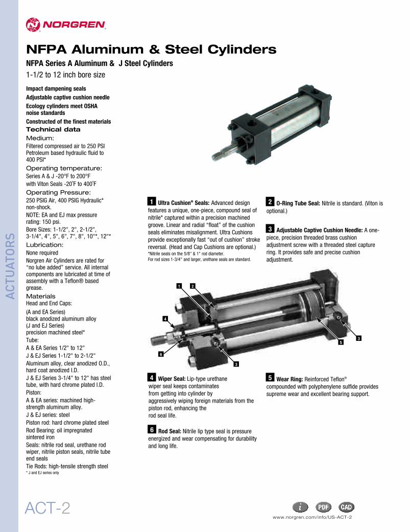
NFPA Aluminum & Steel CylindersNFPA Series A Aluminum & J Steel Cylinders1-1/2 to 12 inch bore size
Ultra Cushion® Seals: Advanced designfeatures a unique, one-piece, compound seal ofnitrile* captured within a precision machinedgroove. Linear and radial “float” of the cushionseals eliminates misalignment. Ultra Cushionsprovide exceptionally fast “out of cushion” strokereversal. (Head and Cap Cushions are optional.)*Nitrile seals on the 5/8" & 1" rod diameter.For rod sizes 1-3/4" and larger, urethane seals are standard.
Adjustable Captive Cushion Needle: A one-piece, precision threaded brass cushionadjustment screw with a threaded steel capturering. It provides safe and precise cushionadjustment.
Wear Ring: Reinforced Teflon®
compounded with polyphenylene sulfide providessupreme wear and excellent bearing support.
5
Rod Seal: Nitrile lip type seal is pressureenergized and wear compensating for durabilityand long life.
6
1
Wiper Seal: Lip-type urethanewiper seal keeps contaminatesfrom getting into cylinder byaggressively wiping foreign materials from thepiston rod, enhancing therod seal life.
3
4
1 2
3
35
4
O-Ring Tube Seal: Nitrile is standard. (Viton isoptional.)
2
6
ACT-3
ACTU
ATORS
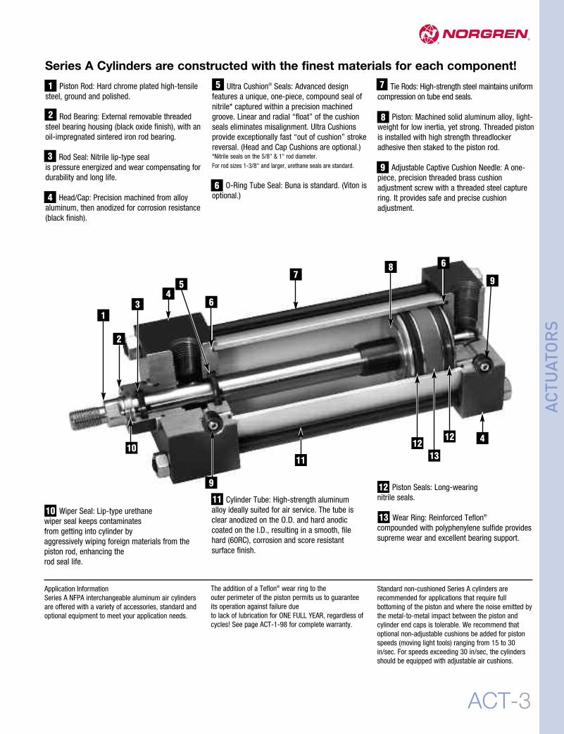
Ultra Cushion® Seals: Advanced designfeatures a unique, one-piece, compound seal ofnitrile* captured within a precision machinedgroove. Linear and radial “float” of the cushionseals eliminates misalignment. Ultra Cushionsprovide exceptionally fast “out of cushion” strokereversal. (Head and Cap Cushions are optional.)*Nitrile seals on the 5/8" & 1" rod diameter.For rod sizes 1-3/8" and larger, urethane seals are standard.
O-Ring Tube Seal: Buna is standard. (Viton isoptional.)
Cylinder Tube: High-strength aluminumalloy ideally suited for air service. The tube isclear anodized on the O.D. and hard anodiccoated on the I.D., resulting in a smooth, filehard (60RC), corrosion and score resistantsurface finish.
Tie Rods: High-strength steel maintains uniformcompression on tube end seals.
Piston: Machined solid aluminum alloy, light-weight for low inertia, yet strong. Threaded pistonis installed with high strength threadlockeradhesive then staked to the piston rod.
Adjustable Captive Cushion Needle: A one-piece, precision threaded brass cushionadjustment screw with a threaded steel capturering. It provides safe and precise cushionadjustment.
6
Piston Seals: Long-wearingnitrile seals.
Wear Ring: Reinforced Teflon®
compounded with polyphenylene sulfide providessupreme wear and excellent bearing support.
Standard non-cushioned Series A cylinders arerecommended for applications that require fullbottoming of the piston and where the noise emitted bythe metal-to-metal impact between the piston andcylinder end caps is tolerable. We recommend thatoptional non-adjustable cushions be added for pistonspeeds (moving light tools) ranging from 15 to 30in/sec. For speeds exceeding 30 in/sec, the cylindersshould be equipped with adjustable air cushions.
1112
13
Piston Rod: Hard chrome plated high-tensilesteel, ground and polished.
Rod Bearing: External removable threadedsteel bearing housing (black oxide finish), with anoil-impregnated sintered iron rod bearing.
Rod Seal: Nitrile lip-type sealis pressure energized and wear compensating fordurability and long life.
Head/Cap: Precision machined from alloyaluminum, then anodized for corrosion resistance(black finish).
1
2
3
5
Wiper Seal: Lip-type urethanewiper seal keeps contaminatesfrom getting into cylinder byaggressively wiping foreign materials from thepiston rod, enhancing therod seal life.
Application InformationSeries A NFPA interchangeable aluminum air cylindersare offered with a variety of accessories, standard andoptional equipment to meet your application needs.
7
8
9
The addition of a Teflon® wear ring to theouter perimeter of the piston permits us to guaranteeits operation against failure dueto lack of lubrication for ONE FULL YEAR, regardless ofcycles! See page ACT-1-98 for complete warranty.
4
10
Series A Cylinders are constructed with the finest materials for each component!
2
1
7
3 6
6
45
89
4
1312
12
1110
9
www.norgren.com/info/US-ACT-4ACT-4
NFPA Aluminum & Steel Cylinders
ACTU
ATORS
12
2 2
3
4
7
1381
11
9
48
10
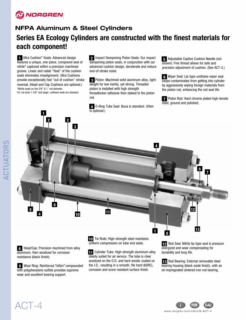
Tie Rods: High-strength steel maintainsuniform compression on tube end seals.
Cylinder Tube: High-strength aluminum alloyideally suited for air service. The tube is clearanodized on the O.D. and hard anodic coated onthe I.D., resulting in a smooth, file hard (60RC),corrosion and score resistant surface finish.
Rod Seal: Nitrile lip-type seal is pressureenergized and wear compensating fordurability and long life.
Rod Bearing: External removable steelbearing housing (black oxide finish), with anoil-impregnated sintered iron rod bearing.
11
10
13
Ultra Cushion® Seals: Advanced designfeatures a unique, one-piece, compound seal ofnitrile* captured within a precision machinedgroove. Linear and radial “float” of the cushionseals eliminates misalignment. Ultra Cushionsprovide exceptionally fast “out of cushion” strokereversal. (Head and Cap Cushions are optional.)*Nitrile seals on the 5/8" & 1" rod diameter.For rod sizes 1-3/8" and larger, urethane seals are standard.
Impact Dampening Piston Seals: Our impactdampening piston seals, in conjunction with ouradvanced cushion design, decelerate and reduceend-of-stroke noise.
Piston: Machined solid aluminum alloy, light-weight for low inertia, yet strong. Threadedpiston is installed with high strengththreadlocker adhesive then staked to the pistonrod.
O-Ring Tube Seal: Buna is standard. (Vitonis optional.)
21
3
Adjustable Captive Cushion Needle (notshown): Fine thread allows for safe andprecision adjustment of cushion. (See ACT-5.)
Wiper Seal: Lip-type urethane wiper sealkeeps contaminates from getting into cylinderby aggressively wiping foreign materials fromthe piston rod, enhancing the rod seal life.
Piston Rod: Hard chrome plated high-tensilesteel, ground and polished.
4
7
5
Head/Cap: Precision machined from alloyaluminum, then anodized for corrosionresistance (black finish).
Series EA Ecology Cylinders are constructed with the finest materials foreach component!
6
ACT-5
NFPA Aluminum & Steel Cylinders
ACTU
ATORS
Energy AbsorptionCapacity of the ImpactDampening Seals
The impact-dampening Piston Seals in theSeries EA cylinder allow for guaranteed,repeatable cushioning. The compressivequalities of the piston seals are predictable.The degree of seal compression at varioussupply pressures is documented. (See EnergyAbsorption Chart.) This allows you to computethe exact cylinder size required by knowing theweight (pounds) you are stopping at a givenspeed.
Series EA cylinders have a impact dampeningpiston seal that accomplishes 80% of theactual load stopping. The air cushion accountsfor only 20%. (A conventional air cushioningcylinder depends 100% on the compressibilityof air to do the stopping.) The EA seal absorbshigh impact loads allowing the effect of the aircushion to be reduced by using a larger aircushion bleed orifice. As a result the piston canmove at a faster speed for a longer period oftime before the EA seal does the final stopping.See illustration at top of ACT-4 for cushionoperation.
3
Norgren Ecology Cylinders offer these advantages:Norgren GuaranteesNon-lubricated Operationfor a Full Year!
The piston rod is self-lubricated by the oil-impregnated rod bearing during operation.Lubrication between piston and cylinder barrel isderived from the polishing qualities of thereinforced Teflon® wear ring.
The low friction surfaces extend the life of theseals beyond normal expectations, permittingNorgren to unconditionally guaranteenon-lubricated operation for one full year.
Series EA cylinders are NFPA interchangeableand are available in many different mountingstyles.
Operates Quietlyto MeetOSHA Specifications.
Series EA cylinders provide substantialreductions in impact noise, which reduces overallmachine noise and helps meet governmentregulations.
The summary of sound decibels chart illustratesthe operating sound levels.
The impact dampening qualities of the PistonSeals are guaranteed for ONE FULL YEAR!
1 2Summary of Sound Levels in Decibels
+ Peak sound pressure is given in decibels (dB)re:2 x 10⁵ N/m2.
++End position of mike was 3' on centerline from end ofcylinder; side position of mike was 3' perpendicular tocenterline abeam of end of cylinder.
Note: At 5 feet, cylinder sound levels would be less by 9 dB fromside figure and 13 dB from end figure. The total noise emitted willdepend on the structure to which the cylinder is attached. If it ismounted on a thin flat plate of considerable area, the noise willbe increased by a sounding board effect.
Effect of Impact Dampening Seals on Total Stroke of Cylinders
*The weight of the cylinder piston has been deducted from the figures shown above.Note: The use of Viton® Seals limits the absorption of the impact dampening seals by 50%.
Energy Absorption Capacity of the Impact Dampening Seals*Usable Pounds Stoppable at the Following Piston SpeedsThis chart features the energy absorption capacity of the impact dampening piston seals with Non-Adjustablecushions. For higher loads and velocities please refer to the Decel-Air™ Cushion Option on ACT-1-9.
Note: These figures are for new cylinders. The impact dampening seals will take some compression set during operationof the cylinder and the stroke loss will decrease. Also, the pressure at zero stroke loss will decrease to about 80 psi.At pressures above those of zero stroke loss, a slight clicking sound may be produced during impact.To determine the stroke loss for either the head or cap end, divide the value shown by 2.
Side Loading:Cylinders are specifically designed to push andpull. Side loading(misalignment)of the piston rodshould be avoided to ensure maximum operatingperformance and life.
Care should be taken during installation toproperly align the load to be moved with thecenter line of the cylinder.The use of a rod alignment coupler (see pageACT-1-94) is strongly recommended wheneverpossible.
Lubrication:None requiredNorgren Air Cylinders are rated for “no lubeadded” service. All internal components arelubricated at time of assembly with a Teflon®
Air Cylinder Selection:The proper application and selection of an aircylinder requires full consideration of thefollowing: the fluid medium, operating pressures,mounting style, length of stroke, type of rodconnection to the load, thrust or mounting tensionon the rod, mounting attitude, speed of the strokeand how the load motion will be stopped.
The data that follows provides the necessaryinformation in the evaluation of
an average application and will help you inselecting the proper cylinder model and size foryour particular application.
Note: 1-1/2", 2", 2-1/2", 3-1/4", 4" and 5" borecylinders with 1/2" to 2" strokes will be furnishedwith a short head cushion sleeve and short capcushion spear.Only available on 5/8" and 1" rods.
The above specification applies to Series EAcylinders with standard non-adjustable or optionaladjustable cushions.
Series EA Fixed Cushions
Piston and rod assemblyfor 1-1/2" thru 5"bore cylinders withless than 1/2" stroke,and 6" thru 8"bore cylinderswith less than 2" stroke.
Piston and rod assembly for1-1/2" thru 5" bore cylinderswith 1/2" to 2" stroke.
A Major Design and PerformanceBreakthrough in Air Cylinder CushioningSystems!Norgren’s advanced cushion design features a unique,one-piece, nitrile compound seal that is captured withina precision machined groove. This allows both linear andradial “float” of the cushion seal which virtuallyeliminates problems associated with misalignment.Integral flow paths molded in the periphery of the sealprovide exceptionally fast “out of cushion” strokereversal without the use of ball checks.
On the reverse stroke the EJ seal releases its compressiveenergy to propel the piston away from the end caps,producing an immediate breakaway.
As the piston continues its travel to the point of impact with theend caps, the compressive qualities of the EJ seal provide thefinal decelerating force. This action compresses the EJ seal andabsorbs the remaining kinetic shock vibration and noisecreated by the impact.
As the cushion spear enters the cushion cavity, the exhaustport becomes sealed off creating an air brake.This providesthe initial deceleration in piston speed. The oversized aircushion bleed orifice permits the cushion pressure to exhaustwith minimal restriction. This allows the piston to movequickly and smoothly through the cushion length.
Cushion FunctionNFPA Aluminum & Steel Cylinders
ACTU
ATORS
ACT-7
NFPA Aluminum & Steel Cylinders
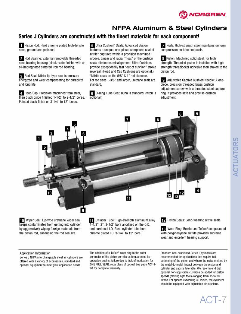
Series J Cylinders are constructed with the finest materials for each component!Ultra Cushion® Seals: Advanced design
features a unique, one-piece, compound seal ofnitrile* captured within a precision machinedgroove. Linear and radial “float” of the cushionseals eliminates misalignment. Ultra Cushionsprovide exceptionally fast “out of cushion” strokereversal. (Head and Cap Cushions are optional.)*Nitrile seals on the 5/8" & 1" rod diameter.For rod sizes 1-3/8" and larger, urethane seals arestandard.
O-Ring Tube Seal: Buna is standard. (Viton isoptional.)
Cylinder Tube: High-strength aluminum alloy1-1/2", 2", 2-1/2" bore anodized on the O.D.and hard coat I.D. Steel cylinder tube hardchrome plated I.D. 3-1/4" to 12" bore.
Tie Rods: High-strength steel maintains uniformcompression on tube end seals.
Piston: Machined solid steel, for highstrength. Threaded piston is installed with highstrength threadlocker adhesive then staked to thepiston rod.
Adjustable Captive Cushion Needle: A one-piece, precision threaded brass cushionadjustment screw with a threaded steel capturering. It provides safe and precise cushionadjustment.
Standard non-cushioned Series J cylinders arerecommended for applications that require fullbottoming of the piston and where the noise emitted bythe metal-to-metal impact between the piston andcylinder end caps is tolerable. We recommend thatoptional non-adjustable cushions be added for pistonspeeds (moving light tools) ranging from 15 to 30in/sec. For speeds exceeding 30 in/sec, the cylindersshould be equipped with adjustable air cushions.
11 12
13
Piston Rod: Hard chrome plated high-tensilesteel, ground and polished.
Rod Bearing: External removable threadedsteel bearing housing (black oxide finish), with anoil-impregnated sintered iron rod bearing.
Rod Seal: Nitrile lip-type seal is pressureenergized and wear compensating for durabilityand long life.
Head/Cap: Precision machined from steel,then black oxide finished 1-1/2" to 2-1/2" bores.Painted black finish on 3-1/4" to 12" bores.
1
2
3
5
Wiper Seal: Lip-type urethane wiper sealkeeps contaminates from getting into cylinderby aggressively wiping foreign materials fromthe piston rod, enhancing the rod seal life.
Application InformationSeries J NFPA interchangeable steel air cylinders areoffered with a variety of accessories, standard andoptional equipment to meet your application needs.
7
8
9
The addition of a Teflon® wear ring to the outerperimeter of the piston permits us to guarantee itsoperation against failure due to lack of lubrication forONE FULL YEAR, regardless of cycles! See page ACT-1-98 for complete warranty.
4
10
2
1
7
3 64
58
9
4
1312 1211
10
9
6
ACTU
ATORS
www.norgren.com/info/US-ACT-8ACT-8
NFPA Aluminum & Steel Cylinders
ACTU
ATORS
12
2
23
4
67
1381
11
9
48
10
1
Tie Rods: High-strength steel maintainsuniform compression on tube end seals.
Cylinder Tube: High-strength aluminum alloy1-1/2", 2". 2-1/2" bore anodized on the O.D.and hard coat I.D. Steel cylinder tube hardchrome plated I.D. 3-1/4" to 12" bore.
Rod Seal: Nitrile lip-type seal is pressureenergized and wear compensating for durabilityand long life.
Rod Bearing: External removable steelbearing housing (black oxide finish), with an oil-impregnated sintered iron rod bearing.
11
10
13
Piston Rod: Hard chrome plated high-tensilesteel, ground and polished.
Head/Cap: Precision machined from steel,then black oxide finished 1-1/2" to2-1/2" bores. Painted black finish 3-1/4"to 12" bores.
Wear Ring: Reinforced Teflon®
compounded with polyphenylene sulfide providessupreme wear and excellent bearing support.
7
8
9
12
Series EJ Ecology Cylinders are constructed with the finest materials foreach component!
Ultra Cushion® Seals: Advanced designfeatures a unique, one-piece, compound seal ofnitrile* captured within a precision machinedgroove. Linear and radial “float” of the cushionseals eliminates misalignment. Ultra Cushionsprovide exceptionally fast “out of cushion”stroke reversal. (Head and Cap Cushions areoptional.)*Nitrile seals on the 5/8" & 1" rod diameter.For rod sizes 1-3/8" and larger, urethane seals are standard.
Impact Dampening Piston Seals: Our impactdampening piston seals, in conjunction with ouradvanced cushion design, decelerate and reduceend-of-stroke noise.
Piston: Machined solid steel, for high strength.Threaded piston is installed with high strengththreadlocker adhesive then staked to the pistonrod.
21
3
O-Ring Tube Seal: Buna is standard. (Vitonis optional.)
Adjustable Captive Cushion Needle (notshown): Fine thread allows for safe and precisionadjustment of cushion. (See page ACT-1-6.)
Wiper Seal: Lip-type urethane wiper sealkeeps contaminates from getting into cylinder byaggressively wiping foreign materials from thepiston rod, enhancing the rod seal life.
Energy AbsorptionCapacity of the ImpactDampening Seals
The impact-dampening Piston Seals in theSeries EJ cylinder allow for guaranteed,repeatable cushioning. The compressivequalities of the piston seals are predictable.The degree of seal compression at varioussupply pressures is documented. (See EnergyAbsorption Chart.) This allows you to computethe exact cylinder size required by knowing theweight (pounds) you are stopping at a givenspeed.
Series EJ cylinders have a impact dampeningpiston seal that accomplishes 80% of theactual load stopping. The air cushion accountsfor only 20%. (A conventional air cushioningcylinder depends 100% on the compressibilityof air to do the stopping.) The EJ seal absorbshigh impact loads allowing the effect of the aircushion to be reduced by using a larger aircushion bleed orifice. As a result the piston canmove at a faster speed for a longer period oftime before the EJ seal does the final stopping.
3
Norgren Ecology Cylinders offer these advantages:
Norgren GuaranteesNon-lubricated Operationfor a Full Year!
The piston rod is self-lubricated by the oil-impregnated rod bearing during operation.Lubrication between piston and cylinder barrel isderived from the polishing qualities of thereinforced Teflon® wear ring.
The low friction surfaces extend the life of theseals beyond normal expectations, permittingNorgren to unconditionally guarantee non-lubricated operation for one full year.
Series EJ cylinders are NFPA interchangeableand are available in many different mountingstyles.
Operates Quietlyto MeetOSHA Specifications.
Series EJ cylinders provide substantial reductionsin impact noise, which reduces overall machinenoise and helps meet government regulations.
The summary of sound decibels chart illustratesthe operating sound levels.
The impact dampening qualities of thePiston Seals are guaranteed for ONE FULL YEAR!
1 2Summary of Sound Levels in Decibels
+ Peak sound pressure is given in decibels (dB)re:2 x 10⁵ N/m2.
++End position of mike was 3' on centerline from end ofcylinder; side position of mike was 3' perpendicular tocenterline abeam of end of cylinder.
Note: At 5 feet, cylinder sound levels would be less by 9 dB fromside figure and 13 dB from end figure. The total noise emitted willdepend on the structure to which the cylinder is attached. If it ismounted on a thin flat plate of considerable area, the noise willbe increased by a sounding board effect.
Effect of Impact Dampening Seals on Total Stroke of Cylinders
*The weight of the cylinder piston has been deducted from the figures shown above.Note: The use of Viton® Seals limits the absorption of the impact dampening seals by 50%.
Energy Absorption Capacity of the Impact Dampening Seals*Usable Pounds Stoppable at the Following Piston SpeedsThis chart features the energy absorption capacity of the impact dampening piston sealswith a Non-Adjustable cushions. For higher loads and velocities please refer to the Decel- Air Cushion.
Note: These figures are for new cylinders. The impact dampening seals will take some compression set during operationof the cylinder and the stroke loss will decrease. Also, the pressure at zero stroke loss will decrease to about 80 psi.At pressures above those of zero stroke loss, a slight clicking sound may be produced during impact.To determine the stroke loss for either the head or cap end, divide the value shown by 2.
PSI Air Sound Cylinder ModelPressure J133B3 EJ155B3 J1133A3 EJ1155A3Level+ 5" x 6" 5" x 6" 2" x 6" 2" x 6"
Supply:Filtered compressed air to 250 PSI Petroleumbased hydraulic fluid to 400 PSI
Side Loading:Cylinders are specifically designed to push andpull. Side loading (misalignment)of the piston rod should be avoided to ensuremaximum operating performance and life.
Care should be taken during installationto properly align the load to be moved with thecenter line of the cylinder.The use of a rod alignment coupler (see pageACT-1-22 is strongly recommended wheneverpossible.
Lubrication:None requiredNorgren Air Cylinders are rated for “no lubeadded” service. All internal components arelubricated at time of assembly with a Teflon®
based grease.
Materials:Head and End Caps: precision
machined steelTube: 6063-T832 aluminum, clear
anodized O.D., hard coat anodized I.D.Rod: hard chrome plated steelPiston: machined high-strength
aluminum alloyRod Bearing: oil impregnated sintered ironSeals: nitrile rod seal, urethane rod wiper,
nitrile piston seals, nitrile tubeend seals
Tie Rods: high-tensile strength steel
Air Cylinder Selection:The proper application and selection of an aircylinder requires full consideration of thefollowing: the fluid medium, operating pressures,mounting style, length of stroke, type of rodconnection to the load, thrust or mounting tensionon the rod, mounting attitude, speed of the strokeand how the load motion will be stopped.
The data that follows provides the necessaryinformation in the evaluation of
an average application and will help you inselecting the proper cylinder model and size foryour particular application.
Note: 1-1/2", 2", 2-1/2", 3-1/4", 4" and 5" borecylinders with 1/2" to 2" strokes will be furnishedwith a short head cushion sleeve and short capcushion spear.Only available on 5/8" and 1" rods.
The above specification applies to Series Jcylinders with optional non-adjustable oradjustable cushions.
Series J Fixed Cushions
Piston and rodassembly for1-1/2" thru 5"bore cylinderswith 1/2" to 2" stroke.
On the reverse stroke the EJ seal releases its compressiveenergy to propel the piston away from the end caps,producing an immediate breakaway.
As the piston continues its travel to the point of impact with theend caps, the compressive qualities of the EJ seal provide thefinal decelerating force. This action compresses the EJ seal andabsorbs the remaining kinetic shock vibration and noisecreated by the impact.
As the cushion spear enters the cushion cavity, the exhaustport becomes sealed off creating an air brake. This providesthe initial deceleration in piston speed. The oversized aircushion bleed orifice permits the cushion pressure to exhaustwith minimal restriction. This allows the piston to movequickly and smoothly through the cushion length.
A Major Design and Performance Breakthroughin Air Cylinder Cushioning Systems!Norgren’s advanced cushion design features a unique, one-piece, nitrile compound seal that is captured within aprecision machined groove. This allows both linear and radial“float” of the cushion seal which virtually eliminates problemsassociated with misalignment. Integral flow paths molded inthe periphery of the seal provide exceptionally fast “out ofcushion” stroke reversal without the use of ball checks.
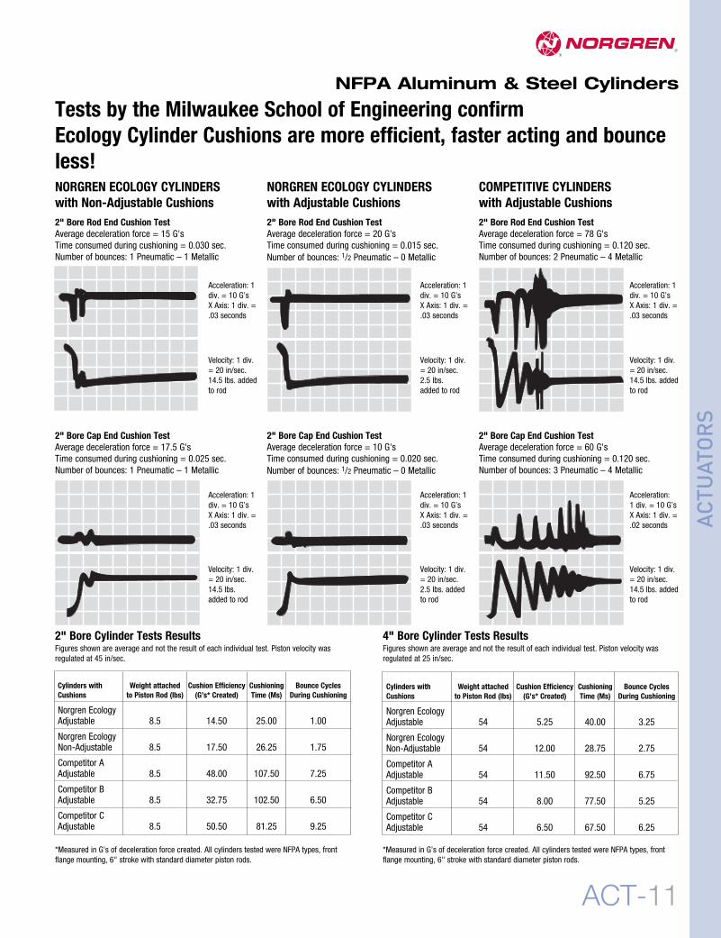
2" Bore Cap End Cushion TestAverage deceleration force = 10 G'sTime consumed during cushioning = 0.020 sec.Number of bounces: 1/2 Pneumatic – 0 Metallic
*Measured in G’s of deceleration force created. All cylinders tested were NFPA types, frontflange mounting, 6" stroke with standard diameter piston rods.
Velocity: 1 div.= 20 in/sec.14.5 lbs. addedto rod
Velocity: 1 div.= 20 in/sec.14.5 lbs. addedto rod
Velocity: 1 div.= 20 in/sec.2.5 lbs. addedto rod
Tests by the Milwaukee School of Engineering confirmEcology Cylinder Cushions are more efficient, faster acting and bounceless!
2" Bore Cylinder Tests ResultsFigures shown are average and not the result of each individual test. Piston velocity wasregulated at 45 in/sec.
NORGREN ECOLOGY CYLINDERSwith Non-Adjustable Cushions2" Bore Rod End Cushion TestAverage deceleration force = 15 G'sTime consumed during cushioning = 0.030 sec.Number of bounces: 1 Pneumatic – 1 Metallic
2" Bore Cap End Cushion TestAverage deceleration force = 60 G'sTime consumed during cushioning = 0.120 sec.Number of bounces: 3 Pneumatic – 4 Metallic
2" Bore Rod End Cushion TestAverage deceleration force = 78 G'sTime consumed during cushioning = 0.120 sec.Number of bounces: 2 Pneumatic – 4 Metallic
2" Bore Rod End Cushion TestAverage deceleration force = 20 G'sTime consumed during cushioning = 0.015 sec.Number of bounces: 1/2 Pneumatic – 0 Metallic
2" Bore Cap End Cushion TestAverage deceleration force = 17.5 G'sTime consumed during cushioning = 0.025 sec.Number of bounces: 1 Pneumatic – 1 Metallic
*Measured in G’s of deceleration force created. All cylinders tested were NFPA types, frontflange mounting, 6" stroke with standard diameter piston rods.
4" Bore Cylinder Tests ResultsFigures shown are average and not the result of each individual test. Piston velocity wasregulated at 25 in/sec.
Explanation of Decel-Air Cushion:Norgren’s Decel Cushioned cylinder was designed for applicationswhere high velocity, low mass, material transfer or machinefunction is required, and where the kinetic energy to be absorbedduring cushioning exceeds the parameters of our standard SeriesEA or EJ air cylinders equipped with non-adjustable or adjustablecushions. Decel cushions employ longer-than-standard aircushions to assist our Impact Dampening Piston Seal.
Why does our Decel-Air Cushion work?The extra cushion length of the Decel cushioned cylinder providesan additional deceleration capability to slow the cylinder’s movingmass to a point where the positive cushioning effect of our ImpactDampening Piston Seals can perform the final cushioning.
Norgren’s Decel-Air Cushioned CylindersVersus
Cylinder Mounted Shock AbsorbersThe first extensive evaluation of pneumatic cylinder cushionperformance was undertaken by the Mechanical EngineeringDepartment of The Ohio State University. The test was conductedon 2-1/2" bore, 12" stroke.The OSU tests found the Decel Cushioned cylinders absorbedalmost three times as much kinetic energy with a lower level ofpeak cushion as a standard Ecology seal configured cylinder.
Because air is compressible and is exhausted out of the cylindereach cycle, the internal heat buildup is minimized. The “MaximumInch Pounds Per Hour” rating which is essential in determiningthe effectiveness of shock absorber performance is not needed tojudge Decel cushion performance.
The test indicated that Norgren Decel-Air Cushioned cylinderscould prove to be superior to a hydralic shock absorber assistedcylinder for high cycle, high velocity applications with light tomoderate loading (precisely the area where most severe cylinderapplications exist). The cycle rates and the cushioning times of theDecel-Air Cushioned cylinders and the hydraulic shock absorberassisted cylinders were comparable.*
Decel-Air Cushioned cylinders are also less costly than shockabsorber mounted cylinders and are self-contained units.
*For comparative evaluation, a well-known hydraulic shockabsorber was chosen. The OSU tests showed a smooth shock-absorbing operation was achieved at very low velocities using theshock absorbers, but at comparable Decel Cushion cylindervelocities, a high mechanical impact took place on the shockabsorber mounted cylinder.
Decel-Air™ Cushioned CylinderEliminates the need for shock absorbers on air cylinder applications.
Ultra Cushion Seals are made of nitrile* captured withina precision machined groove. The seal’s linear andradial “float” eliminates misalignment and providesexceptionally fast “out of cushion” stroke reversal.*Nitrile seals on the 5/8" and 1" rod diameter. For rod sizes 1-3/8" and larger urethane seals are standard.
Extra cushion sleeve and studlength for longer deceleration
Decel-Air Cushion Spacer Blockallows for extra cushion lengthand longer deceleration
Impact Dampening“Ecology” Piston Sealsabsorb final impact andprovide end of strokecushioning assistance.
Adjustable Captive CushionNeedle is a one-piece,precision threaded brasscushion adjustment screwwith a threaded steel capturering. It provides safe andprecise cushion adjustment
2-1/2" - 10.1 lb. + 1.40 lb./in. strokeDouble Weight for double rod end cylinders
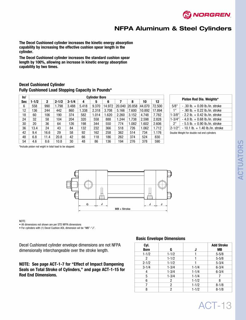
The Decel Cushioned cylinder increases the kinetic energy absorptioncapability by increasing the effective cushion spear length in thecylinder.The Decel Cushioned cylinder increases the standard cushion spearlength by 100%, allowing an increase in kinetic energy absorptioncapability by two times.
G J J J
MB + Stroke
Decel Cushioned cylinder envelope dimensions are not NFPAdimensionally interchangeable over the stroke length.
NOTE: See page ACT-1-7 for “Effect of Impact DampeningSeals on Total Stroke of Cylinders,” and page ACT-1-15 forRod End Dimensions.
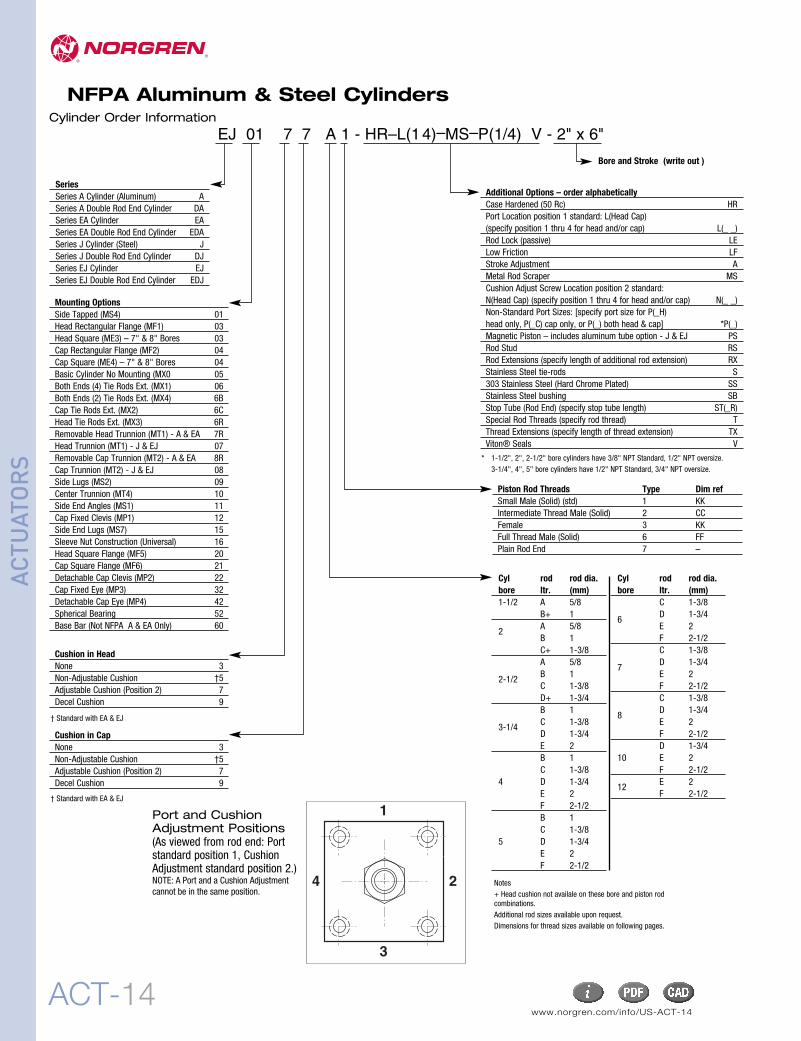
Port and CushionAdjustment Positions(As viewed from rod end: Portstandard position 1, CushionAdjustment standard position 2.)NOTE: A Port and a Cushion Adjustmentcannot be in the same position.
1
3
4 2
Cylinder Order Information
EJ 01 7 7 A 1 - HR–L(14)–MS–P(1/4) V - 2" x 6"
SeriesSeries A Cylinder (Aluminum) ASeries A Double Rod End Cylinder DASeries EA Cylinder EASeries EA Double Rod End Cylinder EDASeries J Cylinder (Steel) JSeries J Double Rod End Cylinder DJSeries EJ Cylinder EJSeries EJ Double Rod End Cylinder EDJ
Mounting OptionsSide Tapped (MS4) 01Head Rectangular Flange (MF1) 03Head Square (ME3) – 7" & 8" Bores 03Cap Rectangular Flange (MF2) 04Cap Square (ME4) – 7" & 8" Bores 04Basic Cylinder No Mounting (MX0 05Both Ends (4) Tie Rods Ext. (MX1) 06Both Ends (2) Tie Rods Ext. (MX4) 6BCap Tie Rods Ext. (MX2) 6CHead Tie Rods Ext. (MX3) 6RRemovable Head Trunnion (MT1) - A & EA 7RHead Trunnion (MT1) - J & EJ 07Removable Cap Trunnion (MT2) - A & EA 8RCap Trunnion (MT2) - J & EJ 08Side Lugs (MS2) 09Center Trunnion (MT4) 10Side End Angles (MS1) 11Cap Fixed Clevis (MP1) 12Side End Lugs (MS7) 15Sleeve Nut Construction (Universal) 16Head Square Flange (MF5) 20Cap Square Flange (MF6) 21Detachable Cap Clevis (MP2) 22Cap Fixed Eye (MP3) 32Detachable Cap Eye (MP4) 42Spherical Bearing 52Base Bar (Not NFPA A & EA Only) 60
Additional Options – order alphabeticallyCase Hardened (50 Rc) HRPort Location position 1 standard: L(Head Cap)(specify position 1 thru 4 for head and/or cap) L(_ _)Rod Lock (passive) LELow Friction LFStroke Adjustment AMetal Rod Scraper MSCushion Adjust Screw Location position 2 standard:N(Head Cap) (specify position 1 thru 4 for head and/or cap) N(_ _)Non-Standard Port Sizes: [specify port size for P(_H)head only, P(_C) cap only, or P(_) both head & cap] *P(_)Magnetic Piston – includes aluminum tube option - J & EJ PSRod Stud RSRod Extensions (specify length of additional rod extension) RXStainless Steel tie-rods S303 Stainless Steel (Hard Chrome Plated) SSStainless Steel bushing SBStop Tube (Rod End) (specify stop tube length) ST(_R)Special Rod Threads (specify rod thread) TThread Extensions (specify length of thread extension) TXViton® Seals V
Piston Rod Threads Type Dim refSmall Male (Solid) (std) 1 KKIntermediate Thread Male (Solid) 2 CCFemale 3 KKFull Thread Male (Solid) 6 FFPlain Rod End 7 –
Notes+ Head cushion not availale on these bore and piston rodcombinations.Additional rod sizes available upon request.Dimensions for thread sizes available on following pages.
Option DescriptionCodeA(–) Stroke adjustment single piston (specify adjustment length)AA(–) Stroke adjustment double piston (specify adjustment length)AN Acorn tie rod nuts (stainless steel)AP Air/Oil piston (piston supplied with O-ring hooded U-cup on cap end for air/oil operation)BL Removable piston rod stud (installed with removable adhesive sealant)EN** Electroless nickel plated cylinderEV(– –) Pneulectric stroke signal valve(s): EV(Head Cap) (specify position)FG Black fiberglass cylinder tubeH Piston rod seals O-ring loaded U-cups – (A & J Only)HR Case hardened piston rodL(– –) Non-standard port location position 1 standard: L (Head Cap) (specify position 1 thru 4 for head and/or cap)LD Rodlock with manual releaseLE RodlockLF Low friction cylinder (Nitrile compounded with Teflon® rod and piston seals) (Not available with Ecology series)MS Metal scraperN(– –) Cushion adjust screw location position 2 standard:N(Head Cap) (specify position 1 thru 4 for head and/or cap)P(–) Non-standard port sizes – [specify port size for P(–H) head only, P(–C) cap only, or P(–) both head & cap]PP Seals in cylinder O-ring loaded U-cups (rod and piston seals) – (A & J Only)PN Pinned piston and rod assemblyPS Magnetic piston modificationRS Studded male piston rod endRX(–) Piston rod extension over standard (specify additional “C” length)S 303/304 Stainless steel tie rods & nutsSB Stainless steel rod bushing nutSC† Single acting spring extend cap end of cylinderSL Steel cylinder tubingSR† Single acting spring retract rod end of cylinderSS 303 Stainless steel piston rodST(–C) Stop tube on cap end (C) of cylinder: ST (stop tube length C)ST(–R) Stop tube on rod end (R) of cylinder: ST (stop tube length R)SV(– –) Stroke signal valve(s): SV (head cap)T(–) Non-standard piston rod thread (specify thread)TF(–) Piston rod thread depth over standard (Female) (specify additional “A” length)TS Stainless cylinder tubingTX(–) Piston rod thread extension over standard (Male) (specify additional “A” length)UB* Head and cap bumpersUC* Cap bumperUH* Head bumper (Adds 1/4" per bumper to overall length)V Viton® seals in cylinderXI(–) Type #10 trunnion set dimension (MT4 model only) (customer must specify length)
Consult Factory for These Options:
†Standard available for 11/2", 2", 2-1/2" bores, 12" max stroke. (Stroke length doubles – 24" max); 12 lbs. force preload, 30 lbs. force compressed.Cushions not available on spring end. For other spring forces, bore sizes or longer strokes, consult factory.*UA Unit Air Assembly** When ordering “EN” option specify S, SS, TS, and SB options.
Option Code DescriptionAS Airsaver stroke adjustmentBB Cylinders mounted back to backCT Close tolerance on cylinder strokeLA Low friction cylinder (Pak-LapTM style seals)NI Nituff® coated cylinderNS No silicone used in cylinder assemblyOE Zero stroke/pneulectric stroke signal valve(s)OV Zero stroke/stroke signal valve(s)RB Rod boot over piston rodTE Nituff® coated cylinder tubingTK Thrust key plate mounting – [01 (MS4), 09 (MS2), and 15 (MS7)VM Valve mounting only
A, EA, J, and EJ Standard and special cylinder options
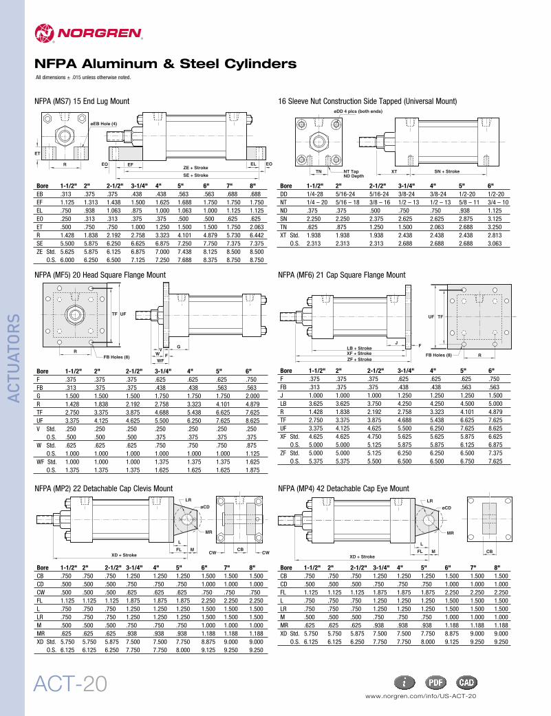
NFPA Aluminum & SteelCylindersNFPA Series A Aluminum & J Steel Cylinders1-1/2 to 12 inch bore size
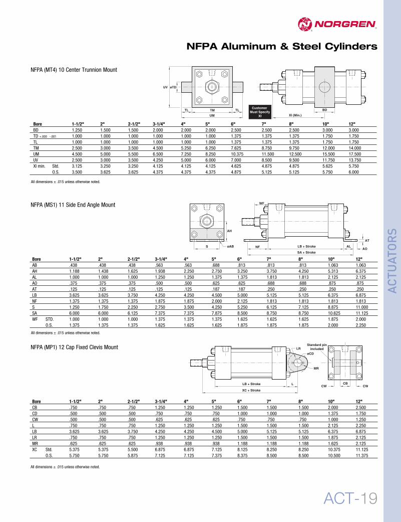
NFPA (ME3) 03 Head Square Mount NFPA (ME4) 04 Cap Square Mount
R C
ZB + Stroke
F
R
DDThds
6C (MX2) 6B (MX4)
ZB + Stroke
BB
DDThds.
6R (MX3)
ZB + Stroke
BB
ZB + Stroke BB
VF K
AA
BB BB
DDThds.
DDThds.
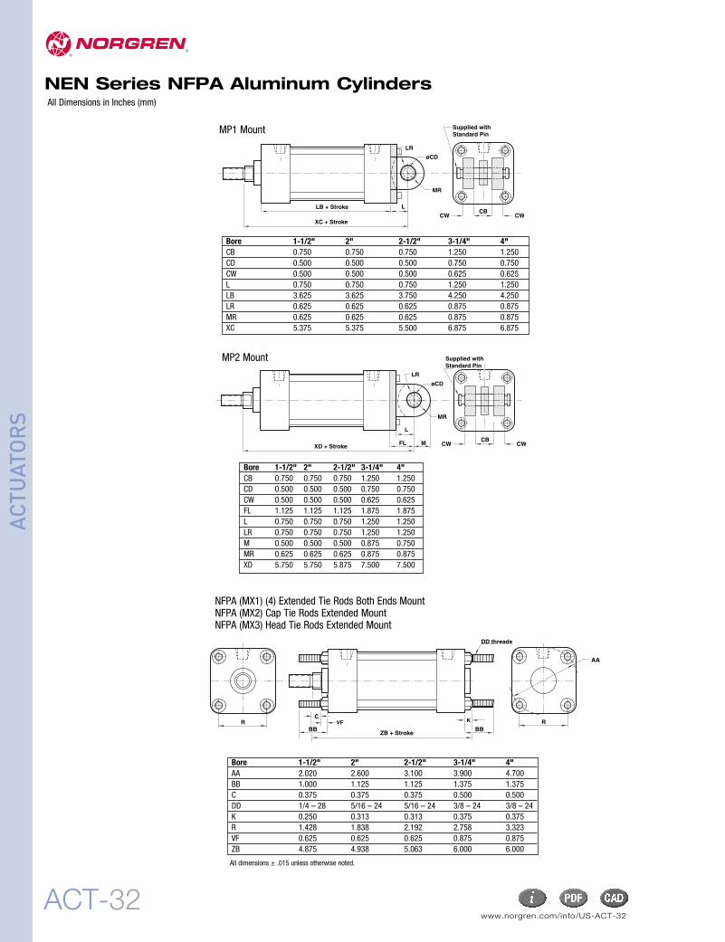
06 (MX1)NFPA (MX1) 06 (4) Extended Tie Rods Both Ends MountNFPA (MX2) 6C Cap Tie Rods Extended MountNFPA (MX3) 6R Head Tie Rods Extended MountNFPA (MX4) 6B (2) Extended Tie Rods Both Ends Mount
All dimensions ± .015 unless otherwise noted.
All dimensions ± .015 unless otherwise noted.
All dimensions ± .015 unless otherwise noted. All dimensions ± .015 unless otherwise noted.
All dimensions ± .015 unless otherwise noted. All dimensions ± .015 unless otherwise noted.
NFPA Aluminum & Steel Cylinders
G Across Flats
øF Shank
.062Radial Float2˚ Spherical
Motion
øB
A Thds.
A Thds.
E E
DC
H AcrossFlats
Rod Alignment CouplerThe Rod Alignment Coupler allows 1/16" of radial float and2° of spherical movement. This prevents cylinder bindingdue to misalignment thusextending bearing and seal life, and permitsgreater tolerance between the centerline of the cylinder andmating part for simplified installation.
Air-Oil TankAvailable in 5 practical bore sizes: 1-1/8", 2", 3-1/4", 5", and8", the Air-Oil Tank includes a translucent fiberglass tubewhich permits viewing of the tank oil level from any position,internal baffles that reduce foaming and aeration of thesystem oil resulting in maximum cylinder control, andstandard angle mounting brackets (except 1-1/8" bore) easilyremoved for convenient fluid port positioning.
Volume of Cylinder:• Cap End Cylinder Bore Area x Stroke = Volume• Head End Cylinder Bore Area – (Piston Rod Area) x Stroke = VolumeLength of Tank = Volume of Cylinder x 1.3*
Tank Bore Area(See chart below.) *30% minimum recommended reserve working volume.
Final Length of Volume of Tank = Working length of tank + 2" minimumsafety factor to prevent aeration of oil. Note: Length must be at least 3".
How to Figure Length of VolumeUse these equations to select the right air/oil tank volume for yourparticular application.
All Dimensions in Inches (mm)All Forces in Pounds (Newtons)
VolumeCu Ft (cm3)
Rod Rod PSI (bar) DisplacementArea 40 (3) 60 (4) 80 (6) 100 (7) 150 (10) 200 (14) Per Inch
Bore Piston PSI (bar) DisplacementArea 40 (3) 60 (4) 80 (6) 100 (7) 150 (10) 200 (14) Per Inch
ACT-25
NFPA Aluminum & Steel Cylinders
ACTU
ATORS
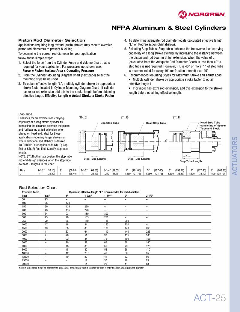
Piston Rod Diameter SelectionApplications requiring long extend (push) strokes may require oversizepiston rod diameters to prevent buckling.To determine the correct rod diameter for your applicationfollow these simple steps:1. Select the force from the Cylinder Force and Volume Chart that is
required for your application. For pressures not shown use:Force = Piston Surface Area x Operating Pressure
2. From the Cylinder Mounting Diagram Chart (next page) select themounting style being used.
3. To obtain effective length “L”, multiply cylinder stroke by appropriatestroke factor located in Cylinder Mounting Diagram Chart . If cylinderhas extra rod extension add this to the stroke length before obtainingeffective length. Effective Length = Actual Stroke x Stroke Factor
4. To determine adequate rod diameter locate calculated effective length“L” on Rod Selection chart (below).
5. Selecting Stop Tubes: Stop tubes enhance the transverse load carryingcapability of a long stroke cylinder by increasing the distance betweenthe piston and rod bearing at full extension. When the value of L(calculated from the Adequate Rod Diameter Chart) is less than 40", astop tube is not required. However, if L is 40" or more, 1" of stop tubeis recommended for every 10" (or fraction thereof) over 40".
6. Recommended Mounting Styles for Maximum Stroke and Thrust Load:• Multiply cylinder stroke by appropriate stroke factor to obtaineffective length L.• If cylinder has extra rod extension, add this extension to the strokelength before obtaining effective length.
Stop TubeEnhances the transverse load carryingcapability of a long stroke cylinder byincreasing the distance between the pistonand rod bearing at full extension whenplaced on head end. Ideal for thoseapplications requiring longer strokes orwhere additional rod stability is desired.TO ORDER: Enter option code ST(–C) CapEnd or ST(–R) Rod End. Specify stop tubelength.NOTE: ST(–R) Alternate design: the stop tuberod end design changes when the stop tubeexceeds J lengths in the chart.
Note: In some cases it may be necessary to use a larger bore cylinder than is required for force in order to obtain an adequate rod diameter.
ACT-26www.norgren.com/info/US-ACT-26
NFPA Aluminum & Steel Cylinders
ACTU
ATORS
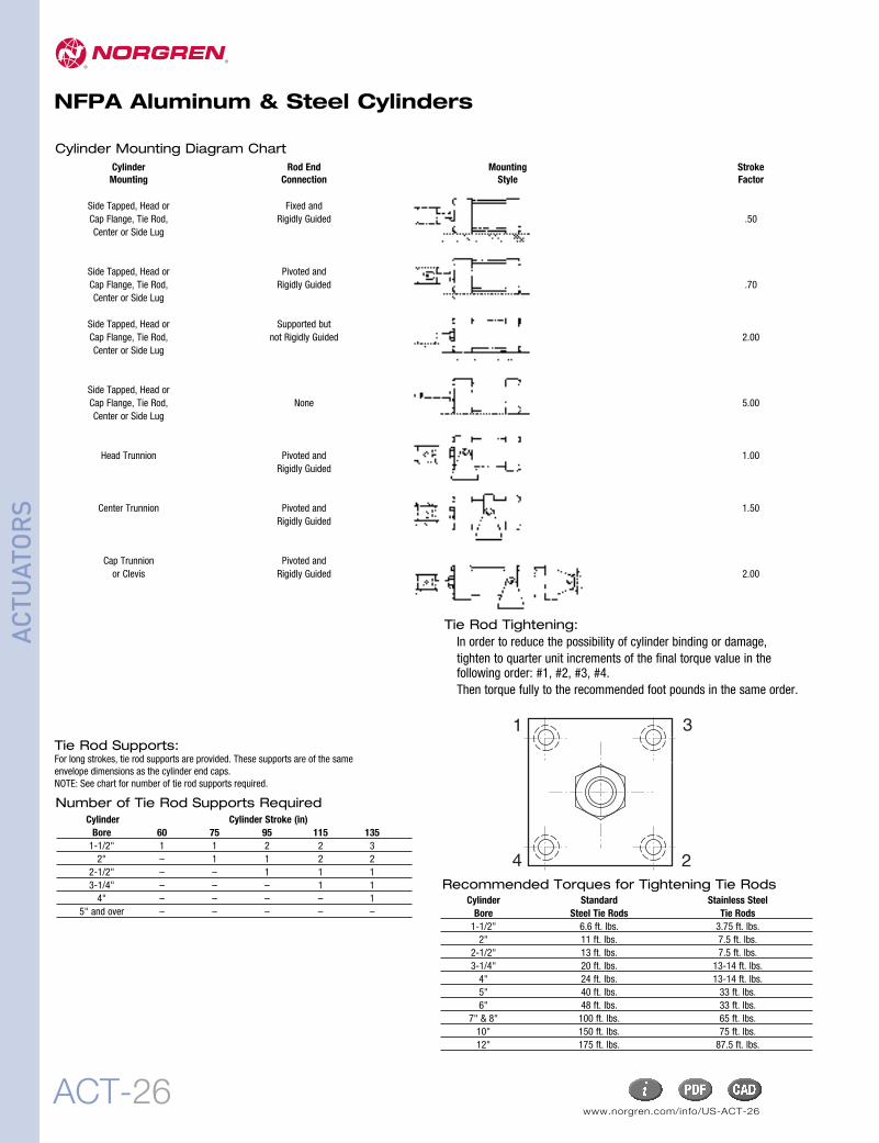
Cylinder Rod End Mounting StrokeMounting Connection Style Factor
Side Tapped, Head or Fixed andCap Flange, Tie Rod, Rigidly Guided .50Center or Side Lug
Side Tapped, Head or Pivoted andCap Flange, Tie Rod, Rigidly Guided .70Center or Side Lug
Side Tapped, Head or Supported butCap Flange, Tie Rod, not Rigidly Guided 2.00Center or Side Lug
Side Tapped, Head orCap Flange, Tie Rod, None 5.00Center or Side Lug
Head Trunnion Pivoted and 1.00Rigidly Guided
Center Trunnion Pivoted and 1.50Rigidly Guided
Cap Trunnion Pivoted andor Clevis Rigidly Guided 2.00
Number of Tie Rod Supports RequiredCylinder Cylinder Stroke (in)Bore 60 75 95 115 1351-1/2" 1 1 2 2 32" – 1 1 2 2
2-1/2" – – 1 1 13-1/4" – – – 1 14" – – – – 1
5" and over – – – – –
Tie Rod Supports:For long strokes, tie rod supports are provided. These supports are of the sameenvelope dimensions as the cylinder end caps.NOTE: See chart for number of tie rod supports required.
Cylinder Mounting Diagram Chart
Tie Rod Tightening:In order to reduce the possibility of cylinder binding or damage,tighten to quarter unit increments of the final torque value in thefollowing order: #1, #2, #3, #4.Then torque fully to the recommended foot pounds in the same order.
1 3
4 2Recommended Torques for Tightening Tie Rods
Cylinder Standard Stainless SteelBore Steel Tie Rods Tie Rods1-1/2" 6.6 ft. lbs. 3.75 ft. lbs.2" 11 ft. lbs. 7.5 ft. lbs.
2-1/2" 13 ft. lbs. 7.5 ft. lbs.3-1/4" 20 ft. lbs. 13-14 ft. lbs.4" 24 ft. lbs. 13-14 ft. lbs.5" 40 ft. lbs. 33 ft. lbs.6" 48 ft. lbs. 33 ft. lbs.
7" & 8" 100 ft. lbs. 65 ft. lbs.10" 150 ft. lbs. 75 ft. lbs.12" 175 ft. lbs. 87.5 ft. lbs.
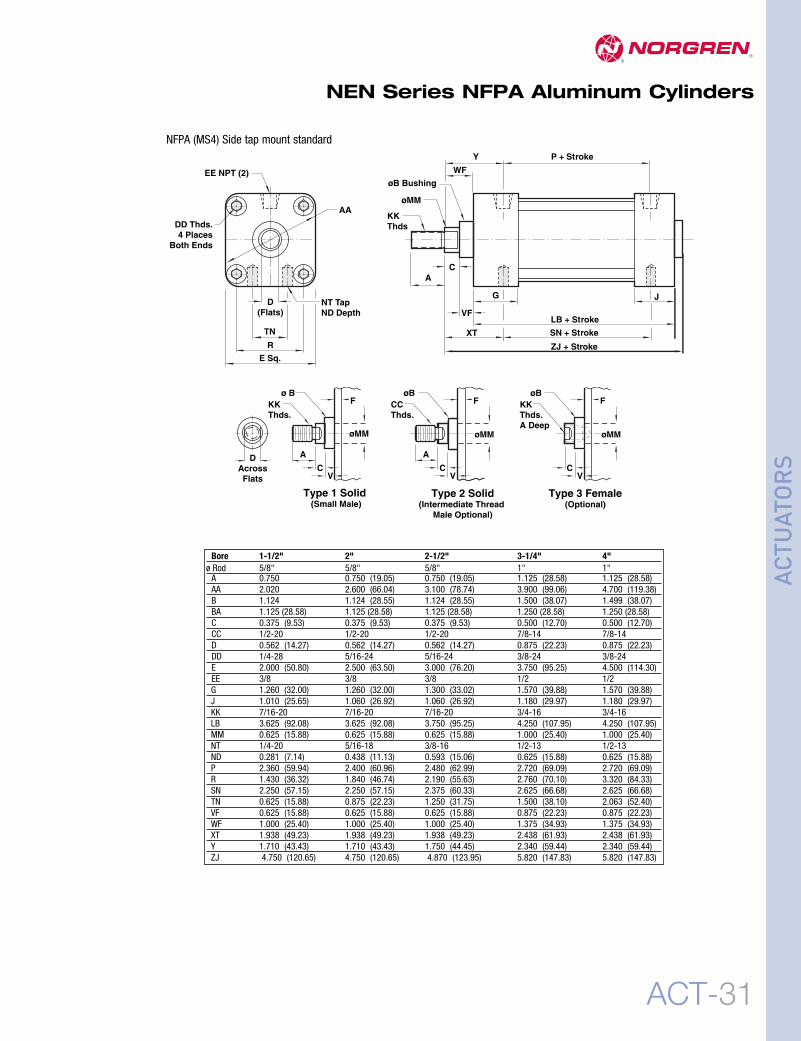
Rod Diameter: 5/8" diameter piston rod in 1-1/2", 2", 2-1/2"
bore
1" diameter piston rod in 3-1/4"
and 4" boreLubrication: None requiredNorgren Air Cylinders are rated for “no lube added” service.
Materials Head and End Caps: Die cast aluminum painted for corrosion protection.
Tube: Aluminum alloy, hard coat anodized
Piston: machined high-strength aluminum casting.
Rod Bearing: clean metal teflon composite
Seals: nitrile rod seal/wiper, nitrile piston seals, nitrile tube end seals
Tie Rods: Nickel plated high-tensile strength steel.
NEN “Add-a-mount” flexibilityNEN cylinders allow you to add NFPA mounts shown below when you order the cylinder from the factory, or add the mounts later.
NFPA MF1 NFPA MF2 NFPA MP1 NFPA MP2
2
7
9
3
4
1
2
11
810
6 5
Piston Rod: Hard chrome plated carbon steel,ground and polished.Head Bearing Housing and cap: Die cast aluminum Tie-Rods: Nickel plated steelPiston: Machined aluminum .Captive Cushion Needle Adjustment: Provides safeand precise cushion adjustment.Wear Ring: Teflon® material provides supreme wearand excellent bearing support.Cylinder Tube: Hard anodized aluminum alloy, withcorrosion and score resistant surface finish.
Piston Rod Wiper/Seal: Abrasion resistant nitrile.Piston Seal: Single Nitrile bi-directional piston seal.Cushion Seal: Nitrile cushion seal is captured withina precision machined groove allowing for linear andradial float eliminating misalignment.Rod Bearing: A composite of Teflon andpolyphenylene sulfide and bronze molded to a steelbacking provides low friction and excellent linearfeatures.
1
2
345
6
7
8910
11
www.norgren.com/info/US-ACT-30ACT-30
NEN Series NFPA Aluminum Cylinders
ACTU
ATORS
Cylinder Order Information
Stock Stroke Cylinders
SeriesNEN
Additional OptionsViton® Seals VRod Extension RXNon-standard piston rod thread TPiston Rod thread extension TXStainless steel piston rod SStainless steel tie rods SS
Piston Rod Threads Small Male (Solid) (std) 1Intermediate Thread Male (Solid) 2Female 3
Bore Single rod 1-1/2" C2.0" D2-1/2" E3-1/4" F4.0" G
Stroke (whole inches) All bores 48" max.*
Mounting Options**MS4 (standard) blankHead Rectangular Flange MF1Cap Rectangular Flange MF2Detachable Cap Clevis MP2Cap Fixed Clevis MP1Tie Rod Extended both ends MX1Tie Rod Extended Cap MX2Tie Rod Extended Head MX3Side Lug Mount MS2
** For factory installed mounts specify mounting option in position 6. If no mount required leave position 6 blank.Mounting kits can be ordered separately
Contact factory for mounting kits, or visit www.norgren.com
Fraction of Stroke length 0 Blank0.125" C0.250 E0.375 G0.500 J0.625 M0.750 P0.875 S
1 2 3 4 5 6 7
NEN 1 C x 4 E – –MP1 V
* Conatact factory for strokes longer than 48".
1-1/2" Bore 2.0" Bore 2-1/2" Bore 3-1/4" Bore 4.0" BoreModel Cylinder Stroke Model Cylinder Stroke Model Cylinder Stroke Model Cylinder Stroke Model Cylinder StrokeNumber Bore Number Bore Number Bore Number Bore Number BoreNEN1C x 1 1-1/2 1.00 NEN1D x 1 2 1.00 NEN1E x 1 2-1/2 1.00 NEN1F x 1 3-1/4 1.00 NEN1G x 1 4 1.00NEN1C x 2 1-1/2 2.00 NEN1D x 2 2 2.00 NEN1E x 2 2 1/2 2.00 NEN1F x 2 3-1/4 2.00 NEN1G x 2 4 2.00NEN1C x 3 1-1/2 3.00 NEN1D x 3 2 3.00 NEN1E x 3 2 1/2 3.00 NEN1F x 3 3-1/4 3.00 NEN1G x 3 4 3.00NEN1C x 4 1-1/2 4.00 NEN1D x 4 2 4.00 NEN1E x 4 2 1/2 4.00 NEN1F x 4 3-1/4 4.00 NEN1G x 4 4 4.00NEN1C x 5 1-1/2 5.00 NEN1D x 5 2 5.00 NEN1E x 5 2 1/2 5.00 NEN1F x 5 3-1/4 5.00 NEN1G x 5 4 5.00NEN1C x 6 1-1/2 6.00 NEN1D x 6 2 6.00 NEN1E x 6 2 1/2 6.00 NEN1F x 6 3-1/4 6.00 NEN1G x 6 4 6.00NEN1C x 8 1-1/2 8.00 NEN1D x 8 2 8.00 NEN1E x 8 2 1/2 8.00 NEN1F x 8 3-1/4 8.00 NEN1G x 8 4 8.00NEN1C x 10 1-1/2 10.00 NEN1D x 10 2 10.00 NEN1E x 10 2 1/2 10.00 NEN1F x 10 3-1/4 10.00 NEN1G x 10 4 10.00NEN1C x 12 1-1/2 12.00 NEN1D x 12 2 12.00 NEN1E x 12 2 1/2 12.00 NEN1F x 12 3-1/4 12.00 NEN1G x 12 4 12.00NEN1C x 14 1-1/2 14.00 NEN1D x 14 2 14.00 NEN1E x 14 2 1/2 14.00 NEN1F x 14 3-1/4 14.00 NEN1G x 14 4 14.00NEN1C x 16 1-1/2 16.00 NEN1D x 16 2 16.00 NEN1E x 16 2 1/2 16.00 NEN1F x 16 3-1/4 16.00 NEN1G x 16 4 16.00NEN1C x 18 1-1/2 18.00 NEN1D x 18 2 18.00 NEN1E x 18 2 1/2 18.00 NEN1F x 18 3-1/4 18.00 NEN1G x 18 4 18.00NEN1C x 20 1-1/2 20.00 NEN1D x 20 2 20.00 NEN1E x 20 2 1/2 20.00 NEN1F x 20 3-1/4 20.00 NEN1G x 20 4 20.00N/A - 24.00 NEN1D x 24 2 24.00 NEN1E x 24 2 1/2 24.00 NEN1F x 24 3-1/4 24.00 NEN1G x 24 4 24.00
MX1 Mount Kit-MK-NEN-MX1Tie Rod extended Both Ends
Kit number DD A BMK-NENC-MX1 1/4-28 1.375 1.375MK-NEND-MX1 5/16-24 1.500 1.500MK-NENE-MX1 5/16-24 1.500 1.500MK-NENF-MX1 3/8-24 1.812 1.937MK-NENG-MX1 3/8-24 1.812 1.937
MX2 Mount Kit-MK-NEN-MX2Tie Rod Extended Cap End
Kit number DD A BMK-NENC-MX2 1/4-28 N/A 1.375MK-NEND-MX2 5/16-24 N/A 1.500MK-NENE-MX2 5/16-24 N/A 1.500MK-NENF-MX2 3/8-24 N/A 1.937MK-NENG-MX2 3/8-24 N/A 1.937
MX3 Mount Kit-MK-NEN-MX3Tie Rod Extended Head End
Kit number DD A BMK-NENC-MX3 1/4-28 1.375 N/AMK-NEND-MX3 5/16-24 1.500 N/AMK-NENE-MX3 5/16-24 1.500 N/AMK-NENF-MX3 3/8-24 1.812 N/AMK-NENG-MX3 3/8-24 1.812 N/A
All dimensions ± .015 unless otherwise noted.
MP1 and MP2 kits come complete with mounting hardware, pivot pin and retaining clips.
A
DD
B
DD
ACT-35
NFPA Aluminum & Steel CylindersNFPA Rodlock LE option Passive
LD option Passive with manual release
ACTU
ATORS
Precision operation maintains accuratepositioning
Large clamping surface ensures consistent performance
Spring-engaged units engage in power-off situations
Sealed to withstand harsh environments
Technical dataBore sizes NFPA cylinders: 1-1/2" to 6" (see chart at right forbore/rod combinations)
Rod lock release pressure: 60 to 120 psi (4 to 8 bar)Caution: Rodlock will not hold a load when mounted to cylinders with operatingpressures in excess of 100 psi (7 bar). Refer to holding force for rod lock chart.
Temperature range: 33°F to 150°F (0.5°C to 66°C)Viton seal option available
Rod lock inlet port: 1/8 NPTRod lock mounting: Any positionHolding: Operates in both directions
NotesIf personal safety is required, an unrelated, redundant safety system should be used.Rod locks require clean, dry, pressure regulated air,lubrication is not required.The rod must be kept clean and dry to maintain optimumholding forces.Rod rotation is not allowed when rod lock is engaged (not intended for torsional braking).
Holding force for rod lockRod Bore Holding* Diameter Size Force0.625 in 1.500 in 180 lbs0.625 in 2.000 in 314 lbs0.625 in 2.500 in 491 lbs1.000 in 3.250 in 830 lbs1.000 in 4.000 in 1257 lbs1.000 in 5.000 in 1960 lbs1.375 in 6.000 in 2825 lbs
* Oversize rod diameters available upon request.* Air assist manual override rod lock available uponrequest.*CAUTION: Rated holding force corresponds tostatic load conditions. If the rated value isexceeded, slipping may occur.
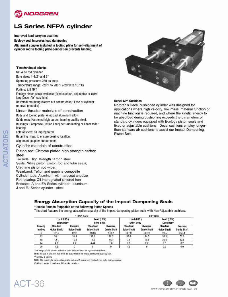
Improved load carrying qualitiesEcology seal improves load dampeningAlignment coupler installed in tooling plate for self-alignment ofcylinder rod to tooling plate connection prevents binding.
Technical dataNFPA tie rod cylinderBore sizes: 1-1/2" and 2"Operating pressure: 250 psi max.Temperature range: -20°F to 200°F (-29°C to 107°C)Porting: 3/8 NPTEcology piston seals available (fixed cushion, adjustable or extralong Decel-Air" cushions)Universal mounting (sleeve nut construction): Ease of cylinderremoval (modular)
Linear thruster materials of constructionBody and tooling plate: Anodized aluminum alloy.Guide rods: Hardened high carbon bearing quality steel.Bushings: Composite (Teflon lined) self-lubricating or linear rollerbearing.Felt washers: oil impregnatedRetaining rings: to ensure bearing location.Alignment coupler: carbon steel
Cylinder materials of constructionPiston rod: Chrome plated high strength carbonsteel Tie rods: High strength carbon steelSeals: Nitrile piston, piston rod and tube seals,Urethane piston rod wiper.Wearband: Teflon and graphite compositeCylinder tube: Aluminum with hardcoat anodizeRod bearing: Oil impregnated sintered ironEndcaps: A and EA Series cylinder - aluminumJ and EJ Series cylinder - steel
Decel-Air" CushionsNorgren's Decel cushioned cylinder was designed forapplications where high velocity, low mass, material function ormachine function is required, and where the kinetic energy tobe absorbed during cushioning exceeds the parameters ofstandard cylinders equipped with Ecology piston seals andfixed or adjustable cushions. Decel cushions employ longer-than-standard air cushions to assist our Impact DampeningPiston Seal.
*The weight of the cylinder piston has been deducted from the figures shown above. Note: The use of Viton® Seals limits the absorption of the impact dampening seals by 50%.** Series J & EJ onlyNOTE: The weight of a tooling plate, guide rods, and 1 extend and 1 retract stop collar has been added.(Guide rod weight is basd on a 6.0" stroke cylinder.)
Energy Absorption Capacity of the Impact Dampening Seals*Usable Pounds Stoppable at the Following Piston SpeedsThis chart features the energy absorption capacity of the impact dampening piston seals with Non-Adjustable cushions.
1-1/2" Bore 2.0" BoreLoad (LBS.) Load (LBS.) Load (LBS.) Load (LBS.)Short Body Long Body Short Body Long Body
Velocity Standard Oversize Standard Oversize Standard Oversize Standard OversizeIn./Sec Guide Shaft Guide Shaft Guide Shaft Guide Shaft Guide Shaft Guide Shaft Guide Shaft Guide Shaft
size 3 (1-1/2" bore) size 4 (2" bore)short body 18" 22"long body 24" 28"
3 4 5 6 7 8 9
2 - Size3 1-1/2"4 2"
7 - Slide Body LengthS shortL long
3 A 3 3 S S C S - Stroke - Options
OptionsAE = stroke adjustment (collar & bumper) - extend strokeAR = stroke adjustment (collar & bumper) - retract strokeCR = corrosion resistance (includes linear slide and cylinder)GL = guide rod lubrication (includes oiler cups installed)GM = guide rod lubrication modification for oiler cupsL() = non-standard port locationME = shock absorber mounting block - extend strokeMR = shock absorber mounting block- retract strokeN() = non-standard adjustable cushion needle locationP() = non-standard port size (down one size = 1/4 NPT, up one size = 1/2 NPT)
PS = magnetic piston (cylinder)PX() = tooling plate extensionTM = side tapped mountingWC = linear thruster assembly without cylinderWS = replacement cylinder without slideV = high temperature viton seals
Dimension Size 3 (1-1/2" Bore) Size 4 (2" Bore)Long body Short body Long body Short body
8 - Guide Rod Bearing TypeC compositeR Roller +, ++
9 - Guide Rod DiameterS standardO oversize
* Non-cushioned cylinders will have U-cup seals as standard.Ecology seals are not available as non-cushioned.** Standard cushion adjustment location is side 1 and adds 1" to the overall length of the cylinder per end with standard port sizes.
+ Roller bearings are not available with oversized guide rods.++ Roller bearing not available with CR (corrosion resistance) option.
3 - Cylinder TypeA aluminum (NFPA tie rod)EA aluminum (NFPA tie rod Ecology SealJ steel (NFPA tie rod)EJ steel (NFPA tie rod Ecology Seal
www.norgren.com/info/US-ACT-38ACT-38
NFPA Aluminum & Steel Cylinders
ACTU
ATORS
1-1/2" bore, 1 inch guide rod, short body, composite bearing
1-1/2" bore, 3/4 inch guide rod, short body, roller bearing
1-1/2" bore, 3/4 inch guide rod, short body, composite bearing
Load and Deflection Graphs
ACT-39
NFPA Aluminum & Steel Cylinders
ACTU
ATORS
1-1/2" bore, 3/4 inch guide rod, long body, roller bearing
Load and Deflection Graphs
1-1/2" bore, 3/4 inch guide rod, long body, composite bearing
1-1/2" bore, 1 inch guide rod, long body, composite bearing
www.norgren.com/info/US-ACT-40ACT-40
ACTU
ATORS
2.0" bore, 1 inch guide rod, long body, composite bearing
2.0" bore, 1 inch guide rod, long body, roller bearing
2.0" bore, 1-3/8 inch guide rod, long body, composite bearing
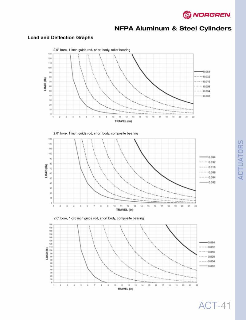
Load and Deflection Graphs
NFPA Aluminum & Steel Cylinders
ACT-41
NFPA Aluminum & Steel Cylinders
ACTU
ATORS
2.0" bore, 1 inch guide rod, short body, roller bearing
2.0" bore, 1 inch guide rod, short body, composite bearing
2.0" bore, 1-3/8 inch guide rod, short body, composite bearing


![D]Q)### D]Q*### D]Q2### · 2020. 1. 10. · õ õ T T T T T T T T T4 #P$) Ú s j n # ¯ õ õ T T T T T T T T $*#P$, Ú m 3 q n 3 c [ ¯ õ õ T T T T T T T T T T T $. Ú s ÷ Æ](https://static.documents.pub/doc/80x56/60ccfb0c192ea8696a7b5b30/dq-dq-dq2-2020-1-10-t-t-t-t-t-t-t-t-t4-p-s-j-n-.jpg)


