84
7.3 NGP Keypad User Guide

7.3
NGP Keypad User Guide
Lenel® OnGuard® 7.3 NGP Keypad User GuideThis guide is item number 55-3600, revision 7.002, May 2016.© 2016 United Technologies Corporation. All rights reserved.
Lenel®, OnGuard® and Prism® (Registered trademarks of UTC Fire & Security Americas Corporation, Inc.) Lenel is a part of UTC Climate, Controls & Security, a unit of United Technologies Corporation.
All trademarks are the property of their respective owners.
Information in this document is subject to change without notice. No part of this document may be reproduced or transmitted in any form or by any means, electronic or mechanical, for any purpose, without the express written permission of UTC Fire & Security Americas Corporation, Inc.
Non-English versions of Lenel documents are offered as a service to our global audiences. We have attempted to provide an accurate translation of the text, but the official text is the English text, and any differences in the translation are not binding and have no legal effect.
The software described in this document is furnished under a license agreement and may only be used in accordance with the terms of that agreement.
Crystal Reports for Windows is a trademark of Crystal Computer Services, Inc.
OnGuard includes ImageStream® Graphic Filters. © 2002 eBT International, Inc. (f/k/a Inso Corporation). All rights reserved. ImageStream Graphic Filters and ImageStream are registered trademarks of eBT International, Inc. (f/k/a Inso Corporation).
Integral and FlashPoint are trademarks of Integral Technologies, Inc.
Portions of this product were created using LEADTOOLS ©1991-2011, LEAD Technologies, Inc. ALL RIGHTS RESERVED. Portions of this product are licensed under US patent 5,327,254 and foreign counterparts.
Active Directory, Microsoft, SQL Server, Windows, and Windows Server are either registered trademarks or trademarks of Microsoft Corporation in the United States and/or other countries.
Oracle is a registered trademark of Oracle and/or its affiliates. Other names may be trademarks of their respective owners.
Other product names mentioned may be trademarks or registered trademarks of their respective companies and are hereby acknowledged.
Warranty
UTC Fire & Security Americas Corporation, Inc. ("Lenel") warrants that the product is free from defects in material and workmanship under normal use and service with proper maintenance for one year from the date of factory shipment. Lenel assumes no responsibility for products damaged by improper handling, misuse, neglect, improper installation, over-voltages, repair, alteration, or accident. This warranty is limited to the repair or replacement of the defective unit. In no event shall Lenel be liable for loss of use or consequential damages of any kind, however occasioned. There are no expressed warranties other than those set forth herein. Warranty expressly excludes third party additions, deletions and/or upgrades to this product, including those

contained herein. Lenel does not make, nor intends, nor does it authorize any agent or representative to make any other warranties or implied warranties, and expressly excludes and disclaims all implied warranties of merchantability or fitness for a particular purpose.
Returned units are repaired or replaced from a stock of reconditioned units. All returns must be accompanied by a return authorization number (RMA) obtained from the Lenel customer service department prior to returning or exchanging any product. The RMA number must appear on the outside of the shipping box and on the packing slip. Any items returned without an RMA number will not be accepted and will be returned at the customer's expense. All returns must have transportation, insurance, and custom brokers' fees prepaid.
Liability
It is expressly understood and agreed that the interface should only be used to control exits from areas where an alternative method for exit is available. This product is not intended for, nor is rated for operation in life-critical control applications. Lenel is not liable under any circumstances for loss or damage caused by or partially caused by the misapplication or malfunction of the product. Lenel's liability does not extend beyond the purchase price of the product.

NGP Keypad User Guide
Table of Contents
Compliance Statements .......................................................9
1. Industry Canada Customer Information .......................................................... 11
1.1 Notices ............................................................................................... 11
1.2 Cautions ............................................................................................. 11
2. Customer Instructions Pertaining to FCC Regulations (North America) ......... 12
2.1 Notices ............................................................................................... 12
2.2 Cautions ............................................................................................. 12
2.3 Warnings (North America, Australia) ................................................. 13
2.4 Restrictions and Requirements for UL Listed Systems ..................... 13
Welcome ............................................................................15
1. Before You Begin ........................................................................................... 17
2. The NGP LCD Keypad ................................................................................... 17
2.1 What You Can Do with the LCD Keypad ........................................... 18
2.2 Keypad Display and Buttons .............................................................. 18
2.3 Logging Into the Keypad (User ID and/or PIN) .................................. 19
2.4 If You Are Being Forced to Enter Protected Premises ...................... 19
2.5 Overview of Screens (Topics) ............................................................ 20
2.6 Keypad Entry Basics .......................................................................... 21
Alarms, Turning Protection On and Off ..............................23
3. Alarm Monitoring Features ............................................................................. 25
4. Audible Keypad Tones ................................................................................... 25
5. Sirens ............................................................................................................. 27
5.1 Conventional Siren ............................................................................ 27
5.2 Voice Siren (optional) ........................................................................ 27
revision 7 — 5
Table of Contents
6. Dealing with Alarms (What to Do If the Keypad Is Beeping) .......................... 27
7. Silencing a False Alarm .................................................................................. 28
8. Using the Emergency Keys ............................................................................ 30
9. Worklate: Extending the Scheduled Closing Time ......................................... 31
10. Suspending Schedules for an Area or Areas ............................................... 32
11. Turning Protection On, Stay, or Viewing the Present Arming-Level ............. 33
12. Turning Protection Off .................................................................................. 35
13. Turning Protection On by Area or Group of Areas ....................................... 36
13.1 Area Priority Protection On/Off ........................................................ 36
13.2 Common Area Protection On/Off ..................................................... 36
13.3 Turning On an Area’s Protection Using an Access Token ............... 37
13.4 Turning Off an Area’s Protection Using an Access Token ............... 37
Checking Status and Controlling Items ..............................39
14. Status and Control Features ......................................................................... 41
15. Using the Function Keys ............................................................................... 42
16. Checking the System Status (Monitored Conditions for Control Unit) .......... 43
17. Checking the Status of Sensors (Points) and Areas .................................... 44
18. Bypassing or Isolating a Faulty Sensor ........................................................ 45
19. Checking the Status or Controlling Readers or Doors .................................. 47
20. Checking the Status of an Application Module (POD) .................................. 49
21. Removing Persistent POD Status or Trouble Messages from the Keypad .. 50
Administration and Maintenance Tasks .............................51
22. Changing Your Own PIN .............................................................................. 53
23. Adding a User to the System ........................................................................ 54
24. Default Authority Settings ............................................................................. 55
25. Viewing or Changing Settings for a User ...................................................... 57
6 — revision 7
NGP Keypad User Guide
26. Deleting a User ............................................................................................. 59
27. Setting the Date and Time ............................................................................ 60
28. Viewing the History ....................................................................................... 61
29. Printing the History Log ................................................................................ 62
30. Changing the Printed History Language ....................................................... 63
31. Testing Monitored Sensors (Performing a Walk Test) .................................. 64
32. Testing Panic Buttons (Performing a Hold-up Test) ..................................... 66
33. Testing Sirens (System Test) ....................................................................... 67
Reference Topics ...............................................................69
34. System Information ....................................................................................... 71
34.1 Contact Information ......................................................................... 71
34.2 System Details ................................................................................. 72
34.3 Function Key Reference .................................................................. 73
35. Arming Station Reference (Option) .............................................................. 74
35.1 Arming Station Commands .............................................................. 74
35.2 Arming Station Lights and Tones/Sirens ......................................... 77
36. Error Messages and Trouble Indications ...................................................... 79
36.1 Keypad Screen Display Error Messages ......................................... 79
36.2 Keypad Yellow Trouble Light ........................................................... 79
36.3 System Status Trouble .................................................................... 79
36.4 Things to Do to Prevent False Alarms ............................................. 80
Index ............................................................................................................. 81
revision 7 — 7

Table of Contents
8 — revision 7

COMPLIANCE STATEMENTS

NGP Keypad User Guide
1 Industry Canada Customer Information
1.1 Notices
This equipment meets the applicable Industry Canada Terminal Equipment Technical Specifications. This is confirmed by the registration number. The abbreviation, IC, before the registration number signifies that registration was performed based on a Declaration of Conformity indicating that Industry Canada technical specifications were met. It does not imply that Industry Canada approved the equipment.
The Ringer Equivalence Number (REN) assigned to each terminal equipment provides an indication of the maximum number of terminals allowed to be connected to a telephone interface. The termination on an interface may consist of any combination of devices subject only to the requirement that the sum of the Ringer Equivalence Numbers of all the devices does not exceed five (5).
The REN for the NGP using the North American Modem is 0.1.
The REN for the NGP using the Worldwide Modem is 0.0.
Repairs to certified equipment should be coordinated by a representative designated by the supplier. Any repairs or alterations made by the user to this equipment, or equipment malfunctions, may give the telecommunications company cause to request the user to disconnect the equipment.
Users should ensure for their own protection that the electrical ground connections of the power utility, telephone lines, and internal metallic water pipe system, if present, are connected together. The precaution may be particularly important in rural areas.
1.2 Cautions
Users should not attempt to make such connections themselves, but should contact the appropriate electric inspection authority, or electrician, as appropriate.
revision 7 — 11
Compliance Statements
2 Customer Instructions Pertaining to FCC Regulations (North America)
2.1 Notices
This equipment complies with the Federal Communications Commission (FCC) rules and regulations governing telephone equipment and the Technical Requirements for Connection to the Telephone Network published by the industry’s Administrative Council for Terminal Attachments (ACTA). On modem board of this equipment is a label that contains, among other information, a product identifier in the format US:AAAEQ##TXXXX. If requested, this number must be provided to the telephone company.
This equipment is designed to be connected to the telephone network or premises wiring using a hard wired connection that does not rely on a modular jack. If a modular jack is installed, it is the responsibility of the installing company to ensure that the jack and/or plug is compliant with the criteria of the telecommunication industry.
The Ringer Equivalence Number (or REN) is used to determine the number of devices that may be connected to a telephone line. Excessive RENs on a telephone line may result in the devices not ringing in response to an incoming call. In most, but not all areas, the sum of RENs should not exceed five (5.0). To be certain of the number of devices that may be connected to a line, as determined by the total RENs, contact the local telephone company.
The REN for the NGP using the North American Modem is 0.2.
The REN for the NGP using the Worldwide Modem is 0.0.
2.2 Cautions
If this equipment (NGP) is deemed potentially harmful to the telephone network, the telephone company will attempt to notify you in advance of discontinuing service. If advance notice is not practical, the telephone company will notify you as soon as possible. If service is disconnected, you will be advised of your right to file a complaint with the Federal Communications Commission (FCC) should you believe it necessary.
The telephone company may make changes in its facilities, equipment, operations, or procedures that could affect the operation of this equipment. Should this occur, advance notice to you will be provided for you to make necessary modifications to maintain uninterrupted service.
If trouble is experienced with this equipment (NGP), for repair or warranty information, please contact the installing company.
If the equipment is causing harm to the telephone network, the telephone company may request that you disconnect the equipment until the problem is resolved.
There are no user serviceable parts which may be repaired by the customer. All repairs must be performed by an authorized dealer representative.
This equipment cannot be used on public coin phone service provided by the telephone company. Connection to party line service is subject to state tariffs. (Contact the state public utility commission, public service commission or corporation commission for information.)
12 — revision 7
NGP Keypad User Guide
2.3 Warnings (North America, Australia)
This equipment has been tested and found to comply with the limits for a Class A digital device, pursuant to Part 15 of the FCC Rules. These limits are designed to provide reasonable protection against harmful interference when the equipment is operated in a commercial environment. This equipment generates, uses, and can radiate radio frequency energy and, if not installed and used in accordance with the instruction manual, may cause harmful interference to radio communications. Operation of this equipment in a residential area is likely to cause harmful interference in which case users will be required to correct the interference at their own expense.
This is a class A product. In a domestic environment this product may cause radio interference in which case the user may be required to take adequate protection measures.
2.4 Restrictions and Requirements for UL Listed Systems
• Access control is not permitted for UL listed residential systems.
• The system must be tested on a weekly basis, including all fire initiating devices. For more information, please refer to Testing Monitored Sensors (Performing a Walk Test) on page 64.
• Detectors and fire initiating devices will be disabled while making programming changes to the system.
Warning Changes or Modifications not expressly approved by Lenel could void the user’s authority to operate this equipment.
revision 7 — 13

Compliance Statements
14 — revision 7

WELCOME


NGP Keypad User Guide
1 Before You Begin
We recommend that you review the operating procedures in this guide while your system is being installed. Ask your security representative/installer to explain any questions that you may have about the various topics.
Please check the Reference Topics section on page 69 that will list information about your alarm system. Ask your security representative/installer to supply the information that should be entered into this section.
2 The NGP LCD Keypad
The NGP LCD (liquid crystal display) keypad provides an integrated 2-line display and multi-function backlit keypad. (The keypad is hidden behind a hinged access cover.)
Keypad LEDs
1. Yellow On: When trouble condition present
Flashing: When there is no AC mains
2. Green On: Always with power present
3. Red Flashing: Protection ON
Solid: Partial protection (STAY)
revision 7 — 17

Welcome
2.1 What You Can Do with the LCD Keypad
NGP LCD keypads provide a convenient local interface that allows:
• Turning protection On and Off.
• Checking status of items.
• Controlling/commanding items.
• Performing administrative tasks.
• Some models can act as a card reader to permit access to locked doors.
2.2 Keypad Display and Buttons
The display is your “window” into the NGP system. When you enter your user ID and/or PIN, you will be given access to all menus and features as assigned through your user authorities.
2.2.1 Buttons Under the Display Screen
The buttons directly under the display screen allow selecting associated items on the display screen. This means the item displayed on the screen above each button.
Note: Like the rest of the keypad, these buttons are backlit for use in poor lighting conditions.
2.2.2 The Numeric Keypad
The main keypad (in the bottom-left portion of the unit) provides a convenient way to enter numbers and letters as well (when applicable).
2.2.3 The Key
This is the escape key, which allows you to return to a previous screen or exit from a menu (log out).
2.2.4 ThearrowKeys on the Keypad
These keys allow selecting different items and topics. When available, the leftor rightarrow keys will appear on-screen.
2.2.5 Emergency Keys and Programmed Function Keys
Pressing a number and the f key at the same time will perform the action as programmed for that key-sequence. The emergency keys at the bottom of the keypad each transmit a specific emergency message (to the central monitoring station).
Note: See Using the Emergency Keys on page 30 and Using the Function Keys on page 42.
18 — revision 7

NGP Keypad User Guide
2.3 Logging Into the Keypad (User ID and/or PIN)
Note: Your security representative/installer will provide your User ID and PIN for pressing into the keypad and logging into the system. (The default Master User ID and PIN is: e.g., ID: 01 or 001, PIN: 7793)
Logging in provides you with access to the features of the LCD keypad. To log in:
Notes: When finished viewing or entering items, you can use the key to exit (press multiple times as needed until the login screen appears).
Tip: You will also be logged out automatically if you do not press any keys for approximately one (1) minute.
2.4 If You Are Being Forced to Enter Protected Premises
If a user is being forced to enter protected premises, entry depends on how the system administrator configured the system. There are two methods:
1. The default method is that the user enters a duress code at the reader keypad or system LCD keypad. The duress code is the PIN with a one (1) added to the last digit, as shown in the following examples:
• If the normal PIN is 1234, then the duress code is 1235.
• If the normal PIN is 5129, then the duress code is 5120.
Note: The NGP reader must be in card & PIN mode. For more information, please refer to Checking the Status or Controlling Readers or Doors on page 47.
2. The second method is to issue two cards, one card for normal use and one card for duress use. If being forced to enter protected premises, the user would present the duress card at the reader.
Note: To configure a duress card in OnGuard, go to System Administration > Access Levels > Permission Profiles > General tab and check the Treat token as panic/duress check box.
Both methods cause a duress (panic) alarm to be triggered in the OnGuard Alarm Monitoring application.
Open the keypad cover and press in your user ID number and/or PIN as indicated on the display.
Welcome Enter ID: _ _ _
Your Name Appears Enter PIN: _ _ _
revision 7 — 19

Welcome
For the duress code method (PIN +1), OnGuard can be configured to grant or deny access, depending on the following setting:
• If the OnGuard > System Administration > Access Control > Reader and Doors > Settings tab option Deny on Duress PIN is enabled (checked), then access will be denied under duress and the event Denied Under Duress will be generated.
• If the OnGuard System Administration > Access Control > Reader and Doors > Settings tab option Deny on Duress PIN is not enabled (unchecked), then access will be granted under duress. The event Granted Under Duress or Granted Under Duress, No Entry will be generated depending on whether or not the door was opened.
2.5 Overview of Screens (Topics)
When logged in, you will see only the topics that you have the authority to use. Some or all of the following topics will be available:
Note: Selecting a Topic: Press thekey until your desired topic appears on-screen. Then press the key directly under your topic to select it.
Off/Stay/On:
The first screen that you will see allows you to arm or disarm the area(s) as desired, or to access other topics.
Status:
This allows checking the status of various items in the system, or commanding items into different states.
Note: Please ignore uncommon status screens that may show up like Comms, Modem, Licns. They are for a service technician’s purposes.
Bypass:
This allows bypassing faulty sensor(s) so the system ignores them, and/or to allow arming the system.
History:
This allows viewing a record of the tasks that users have performed (disarm areas, bypass sensors, etc.)
Only two of arm/disarm selections will appear at a time, depending on the present arming-state of the area(s).
Pushfor MenusStay On
• Off: all intrusion protection fully Off.
• Stay: partial protection. Internal motion detectors disabled. Only perimeter protection On. For users to remain inside the protected area.
• On: all protection fully On. No one remaining in the protected area.
20 — revision 7

NGP Keypad User Guide
My PIN:
This allows the person who is logged in to change his or her password.
Users:
This allows adding or deleting users from the system, or viewing or editing settings for specific users. A User is a person who has the authority to log into system keypads and/or to gain entry at access-controlled doors.
Test:
This allows testing different aspects of the system.
Verify:
This allows you to prove that you are present. This lets a monitoring facility know that you are present after accidentally tripping a sensor and/or silencing a false alarm.
Schdule:
This allows extending the scheduled closing time for an area (the worklate feature) or suspending a schedule altogether.
Arm/Disarm:
Re-enters the screen for turning the system to Off, Stay, or On.
Time:
This allows changing the time and/or date for a system panel.
2.6 Keypad Entry Basics
Use the buttons directly under the display screen when the arrow beside desired subjects on the screen is pointing down to the corresponding keypad buttons.
Theandbuttons allow you to view additional topics, when available. (and/orwill appear on the display screen to indicate these keys can be used.)
Use the escape key when finished with your present menu/topic to return to the main screen or back out of inner screens.
2.6.1 Entering Letters (e.g., for a User’s Name)
The numeric keypad allows entering numbers and letters for items that support this.
When required, press the specific key multiple times until the desired letter appears:
Pressing 2 multiple times produces: 2 A B C on the screen.
Pressing 3 multiple times produces: 3 D E F on the screen.
...etc. (look for the letters on each key).
revision 7 — 21

Welcome
Note: The _ on the 0 (zero) key represents a space.
22 — revision 7
ALARMS, TURNING PROTECTION ON AND OFF


NGP Keypad User Guide
3 Alarm Monitoring Features
Depending on how the system is set up, specific alarms may be indicated by any of the following items:
• An alarm message will appear on specific keypad(s).
• Keypad “sonalerts” (beepers) may sound.
• A local siren may be triggered.
Note: For UL listed systems, a local siren must be triggered.
• An alarm message may be transmitted to a monitoring station (and/or to a management PC running the access control software.
Note: For UL listed systems, an alarm message must be transmitted.
• A programmable “output” may be triggered (this can cause a horn to sound or perform any other type of automated “switching” function).
• A numeric pager may be called to let the wearer know that a specific type of alarm has occurred.
Note: These actions can be fully customized for each type of event, for each arming level that the system can be in at any time (Off, Stay, or fully On).
4 Audible Keypad Tones
The following audible keypad tones accompany keypad visual indications like lights and screen messages. There are two (2) versions for some of the tones to operate:
• Standard: regular tone operation.
• Alternative: opposite to regular operation.
New systems will use Standard tone operation. Alternative tone operation must be especially programmed by a security representative. These tones also apply to the ones emitting from an Arming Station (see Arming Station Reference (Option) on page 74 for details.)
Pressing Keypad Keys/Buttons
• Single short beep
Error Tones for Wrong Keys Pressed
• Six (6) short beeps
revision 7 — 25
Alarms, Turning Proctection On and Off
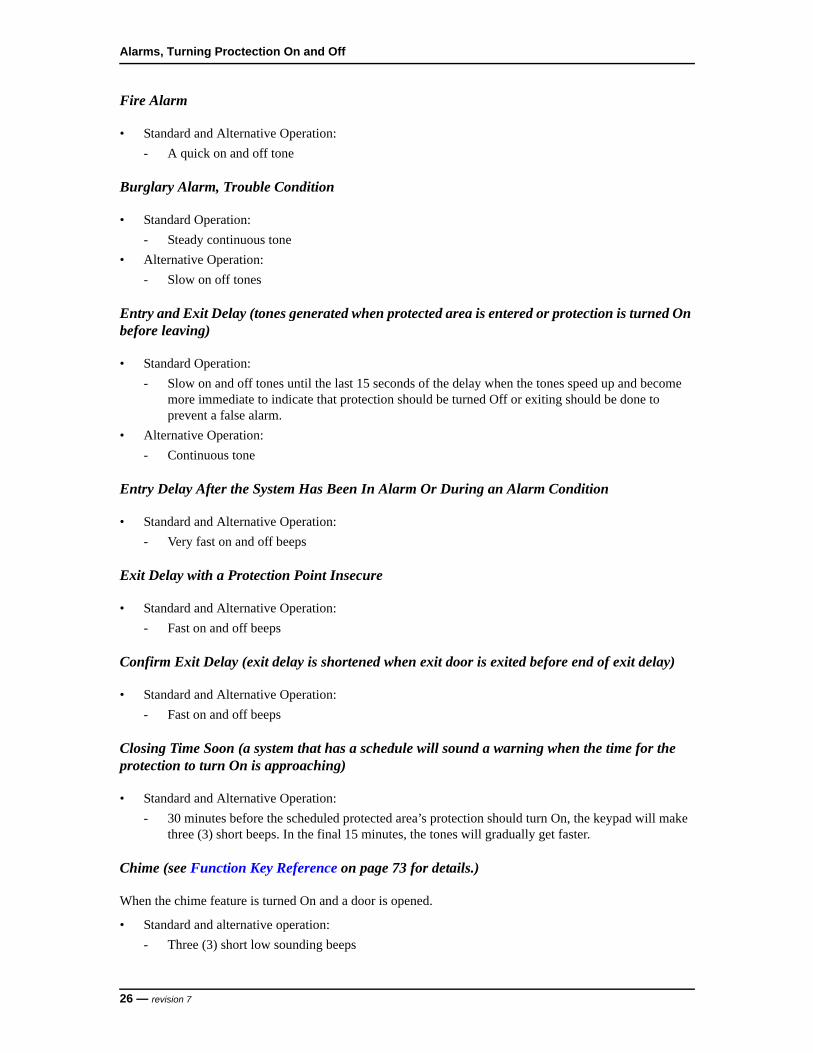
Fire Alarm
• Standard and Alternative Operation:
- A quick on and off tone
Burglary Alarm, Trouble Condition
• Standard Operation:
- Steady continuous tone
• Alternative Operation:
- Slow on off tones
Entry and Exit Delay (tones generated when protected area is entered or protection is turned On before leaving)
• Standard Operation:
- Slow on and off tones until the last 15 seconds of the delay when the tones speed up and become more immediate to indicate that protection should be turned Off or exiting should be done to prevent a false alarm.
• Alternative Operation:
- Continuous tone
Entry Delay After the System Has Been In Alarm Or During an Alarm Condition
• Standard and Alternative Operation:
- Very fast on and off beeps
Exit Delay with a Protection Point Insecure
• Standard and Alternative Operation:
- Fast on and off beeps
Confirm Exit Delay (exit delay is shortened when exit door is exited before end of exit delay)
• Standard and Alternative Operation:
- Fast on and off beeps
Closing Time Soon (a system that has a schedule will sound a warning when the time for the protection to turn On is approaching)
• Standard and Alternative Operation:
- 30 minutes before the scheduled protected area’s protection should turn On, the keypad will make three (3) short beeps. In the final 15 minutes, the tones will gradually get faster.
Chime (see Function Key Reference on page 73 for details.)
When the chime feature is turned On and a door is opened.
• Standard and alternative operation:
- Three (3) short low sounding beeps
26 — revision 7

NGP Keypad User Guide
5 Sirens
5.1 Conventional Siren
Fire Alarm
• Intermittent Tone (same as a Fire Alarm on page 26)
Burglar Alarm:
• Steady Tone
5.2 Voice Siren (optional)
Fire Alarm
• Steady tone, followed by optional voice Fire Alarm Message (e.g., “FIRE! FIRE! ... Leave Immediately!”)
Burglar Alarm:
• On and off tone, followed by optional voice Burglar Alarm Message (e.g., “Intrusion! Intrusion!... The police have been called, leave immediately.”)
6 Dealing with Alarms (What to Do If the Keypad Is Beeping)
If an alarm occurs, you must first decide if it is a valid alarm (break-in, battery failure, etc.) or a false alarm. If a valid alarm occurs, be sure to notify the appropriate persons and/or take steps to either deal with the item yourself, if appropriate, or get yourself and others to safety.
revision 7 — 27
Alarms, Turning Proctection On and Off
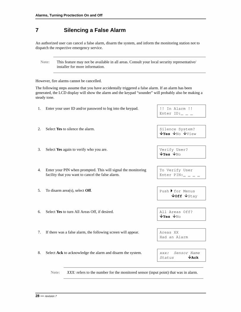
7 Silencing a False Alarm
An authorized user can cancel a false alarm, disarm the system, and inform the monitoring station not to dispatch the respective emergency service.
Note: This feature may not be available in all areas. Consult your local security representative/installer for more information.
However, fire alarms cannot be cancelled.
The following steps assume that you have accidentally triggered a false alarm. If an alarm has been generated, the LCD display will show the alarm and the keypad “sounder” will probably also be making a steady tone.
1. Enter your user ID and/or password to log into the keypad. !! In Alarm !!Enter ID:_ _ _
2. Select Yes to silence the alarm. Silence System?Yes No View
3. Select Yes again to verify who you are. Verify User?Yes No
4. Enter your PIN when prompted. This will signal the monitoring facility that you want to cancel the false alarm.
To Verify UserEnter PIN:_ _ _ _
5. To disarm area(s), select Off. Pushfor MenusOff Stay
6. Select Yes to turn All Areas Off, if desired. All Areas Off?Yes No
7. If there was a false alarm, the following screen will appear. Areas XXHad an Alarm
8. Select Ack to acknowledge the alarm and disarm the system. xxx: Sensor NameStatus Ack
Note: XXX: refers to the number for the monitored sensor (input point) that was in alarm.
28 — revision 7

NGP Keypad User Guide
To return to the main screen (log out), press the escape key a few times, or let the system time-out (1 minute).
Notes: The entry tones will now stop sounding and the selected areas are now fully disarmed.
If the Verify option is used, it must be done within one (1) minute of the false alarm occurring for the station to acknowledge the signal.
9. Press this key to perform another function. Disarming...Next Function
revision 7 — 29

Alarms, Turning Proctection On and Off
8 Using the Emergency Keys
There are three (3) emergency keys that will cause an emergency alarm. This will be transmitted to the monitoring station and may also turn on a local alarm, a programmable output, and/or cause a numeric pager message to be sent (depending on how the system is set up).
To transmit an emergency alarm, press the button on both sides of the specific symbol at the same time.
Alert Keys
Note: Alert keys are only available if they have been ordered by you and supplied by your security representative.
Fire Press the f function key (discussed in Using the Function Keys
on page 42) and the left arrow keyat the same time.
Panic/Police Alarm Press the left and right arrow keysat the same time.
Emergency (non medical) Press the left arrow key and the escape key at the same time.
30 — revision 7

NGP Keypad User Guide
9 Worklate: Extending the Scheduled Closing Time
A Schedule represents the period when, for example, a commercial system is open for normal business hours. If the scheduled closing time is approaching when the protection is turned on and you wish to remain in the area, you can extend the closing time.
To return to the main screen (log out), press the escape key a few times, or let the system time-out (1 minute).
Note: An authorized user may only change the Worklate Schedule for the current day. Fifteen (15) minutes before a Schedule ends, the system will chime indicating that a scheduled closing is pending. At this stage, an authorized user may change the Worklate time to suspend the system closing until a specified time.
1. Enter your user ID and/or PIN to log into the keypad. WelcomeEnter ID:_ _ _
2. Press thearrow keys until you see Schdule. Then select Schdule.
Menu OptionsSchdule Ok
3. Select Schd to change the Schedule for the selected area (e.g., Office), or select Next Area to select a different area.
AreaName.....OffSchd Next Area
4. Select Worklate to change the closing time for your selected area. Close -> 09:30pMoWorklate Susp
5. Select + or - to adjust (Adj) the closing time as desired. ..until 17:30pFrOk + Adj -
Note: The + and - (Adj) keys adjust the closing time by increments of 30 minutes.
6. Once the scheduled closing time is correct, select Ok. ..Until 17:30pFrOk + Adj -
revision 7 — 31

Alarms, Turning Proctection On and Off
10 Suspending Schedules for an Area or Areas
A schedule can be blocked altogether if you do not want a scheduled closing to occur.
To return to the main screen (log out), press the escape key a few times, or let the system time-out (1 minute).
1. Enter your user ID and/or PIN to log into the keypad. WelcomeEnter ID:_ _ _
2. Press thearrow keys until you see Schdule. Then press the key under Schdule to select it.
Menu OptionsSchdule Ok
3. Select Schd to suspend the Schedule for the selected area (e.g., Office) or select Next Area to select a different area.
Area..........OffSchd Next Area
4. Select Susp to suspend the Schedule for the selected area. Close by 17:30pMoWorklate Susp
5. Select Ok to suspend the schedule and return to the main screen. Select Resume to reinstate the schedule.
SuspendedOk Resume
Warning A Schedule will remain suspended indefinitely until Resume is selected.
32 — revision 7
NGP Keypad User Guide
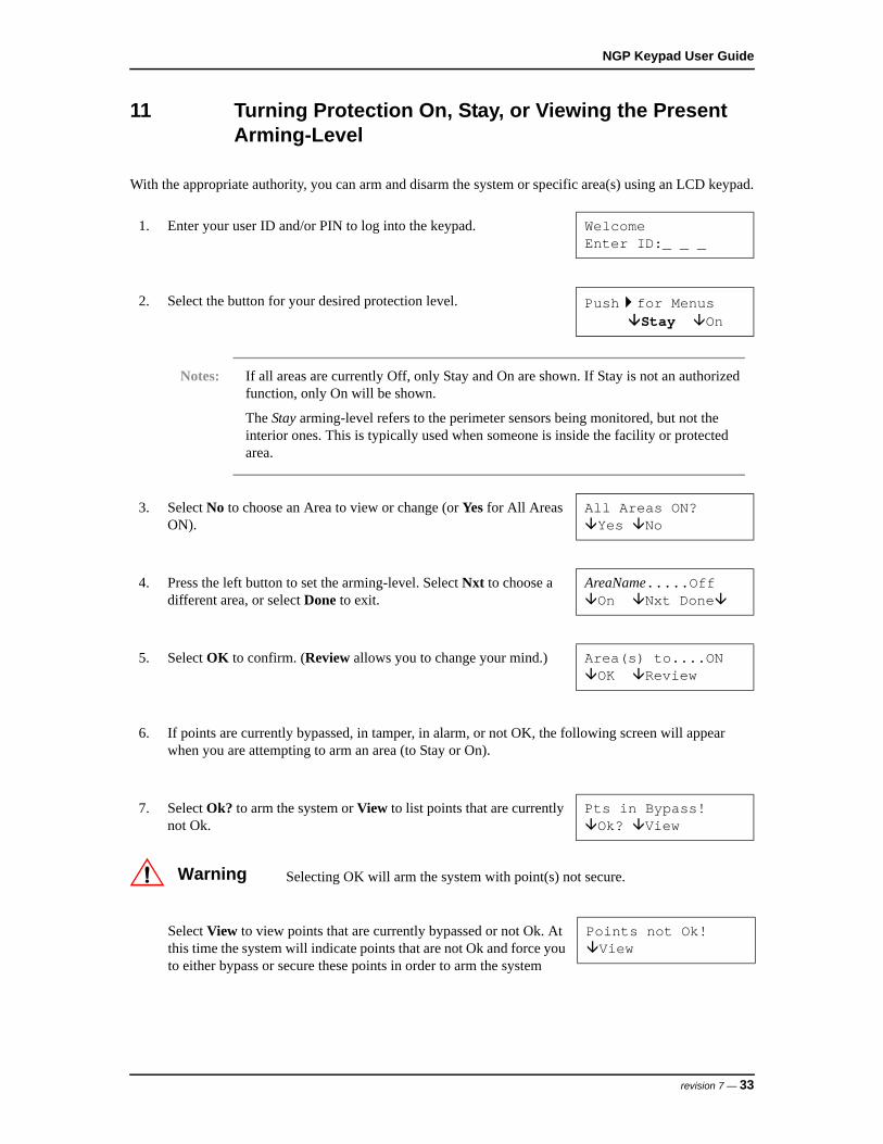
11 Turning Protection On, Stay, or Viewing the Present Arming-Level
With the appropriate authority, you can arm and disarm the system or specific area(s) using an LCD keypad.
1. Enter your user ID and/or PIN to log into the keypad. WelcomeEnter ID:_ _ _
2. Select the button for your desired protection level. Pushfor MenusStay On
Notes: If all areas are currently Off, only Stay and On are shown. If Stay is not an authorized function, only On will be shown.
The Stay arming-level refers to the perimeter sensors being monitored, but not the interior ones. This is typically used when someone is inside the facility or protected area.
3. Select No to choose an Area to view or change (or Yes for All Areas ON).
All Areas ON?Yes No
4. Press the left button to set the arming-level. Select Nxt to choose a different area, or select Done to exit.
AreaName.....OffOn Nxt Done
5. Select OK to confirm. (Review allows you to change your mind.) Area(s) to....ONOK Review
6. If points are currently bypassed, in tamper, in alarm, or not OK, the following screen will appear when you are attempting to arm an area (to Stay or On).
7. Select Ok? to arm the system or View to list points that are currently not Ok.
Pts in Bypass!Ok? View
Warning Selecting OK will arm the system with point(s) not secure.
Select View to view points that are currently bypassed or not Ok. At this time the system will indicate points that are not Ok and force you to either bypass or secure these points in order to arm the system
Points not Ok!View
revision 7 — 33

Alarms, Turning Proctection On and Off
The tone you will hear is a reminder for you to quickly leave the area or premises. During the last 15 seconds this intermittent tone will speed up. The exit tones will now stop sounding and the selected areas are now fully armed.
Select the desired topic:
• Pts: Bypassable points (sensors) in the displayed area
• Next: Show the next area
• All: All bypassable points regardless of area
AreaName.....OffPts Next All
When a point/sensor is displayed, you will have these options:
• : Press the arrow keys to scan through the sensors (points) in the system (or the selected area).
• Bypass: Select this for the system to ignore (bypass) the selected sensor.
• ? jumps to the next point that is not Ok.
xxx: Sensor NameStatus Bypass ?
Once all points have been bypassed or secured, the system will automatically arm.
Arming...BypassNext Function
After arming (On), leave immediately by the designated exit route!
Area(s) armingPlease Leave
34 — revision 7

NGP Keypad User Guide
12 Turning Protection Off
1. When you have entered the area with the protection On, the keypad will beep and the screen will display:
To DisarmEnter ID:_ _ _
2. Enter your user ID and/or PIN to log into the keypad.
3. This screen will display. It allows you to choose turning the area fully Off or putting it in Stay for partial protection.
Pushfor MenusOff Stay
4. After making your selection, this screen will ask if the protection for all areas should be changed, if there is more than one area.
All Areas Off?Yes No
If No is selected, this screen will display the current condition of the available areas, e.g., On and selections for that area.
Selections for other areas are displayed by pressing Nxt, or just change the protection level for the area you are in.
Pressing the button below Done will process the selections you made.
Area 1.........OnOff Nxt Done
revision 7 — 35

Alarms, Turning Proctection On and Off
13 Turning Protection On by Area or Group of Areas
Check with your security representative/installer to have this feature added to your system. You must have the proper authority to control additional protected areas.
13.1 Area Priority Protection On/Off
Priority Arming requires that areas are armed and disarmed in order of their priority. If protection for Area 1 is turned On first, then area 2, and then 3, disarming the areas would then require area 3 to be turned Off first, then area 2, and then 1. This sequence can vary and it is necessary to learn the order from your security representative/installer or system administrator.
13.2 Common Area Protection On/Off
A user who has authority for only certain areas in a multiple area system must be able to enter the entrance to reach his or her areas. At the same time, a user who only has authority for other areas beyond the same entrance must also be able to enter. This can make the main entrance a common area. Both users can have authority for the common area to reach their particular areas. This allows them to be able to turn the protection On and Off to the common area when their authorized areas are in use.
Check with your security representative/installer or system administrator for information and authority for a Common Area.
1. Enter your user ID and/or PIN to log into the keypad. WelcomeEnter ID:_ _ _
2. Select the button for your desired protection level.
• Selecting Stay will supply selections for the areas separately.
• Selecting On will supply the special way to turn area protection on.
Pushfor MenusStay On
3. Select Yes if an authorized user has been assigned with the authority level to turn On a certain group or groups of areas at the same time.
All Areas ON?Yes No
4. If authorized, select No to choose individual Area Groups or Areas to turn On.
Choose Area by?Group Area
• If protection for areas is not turned On or Off in their proper sequence, this error screen will appear and the process will not occur. It will have to be repeated properly.
AREA 1Priority Fail
36 — revision 7
NGP Keypad User Guide
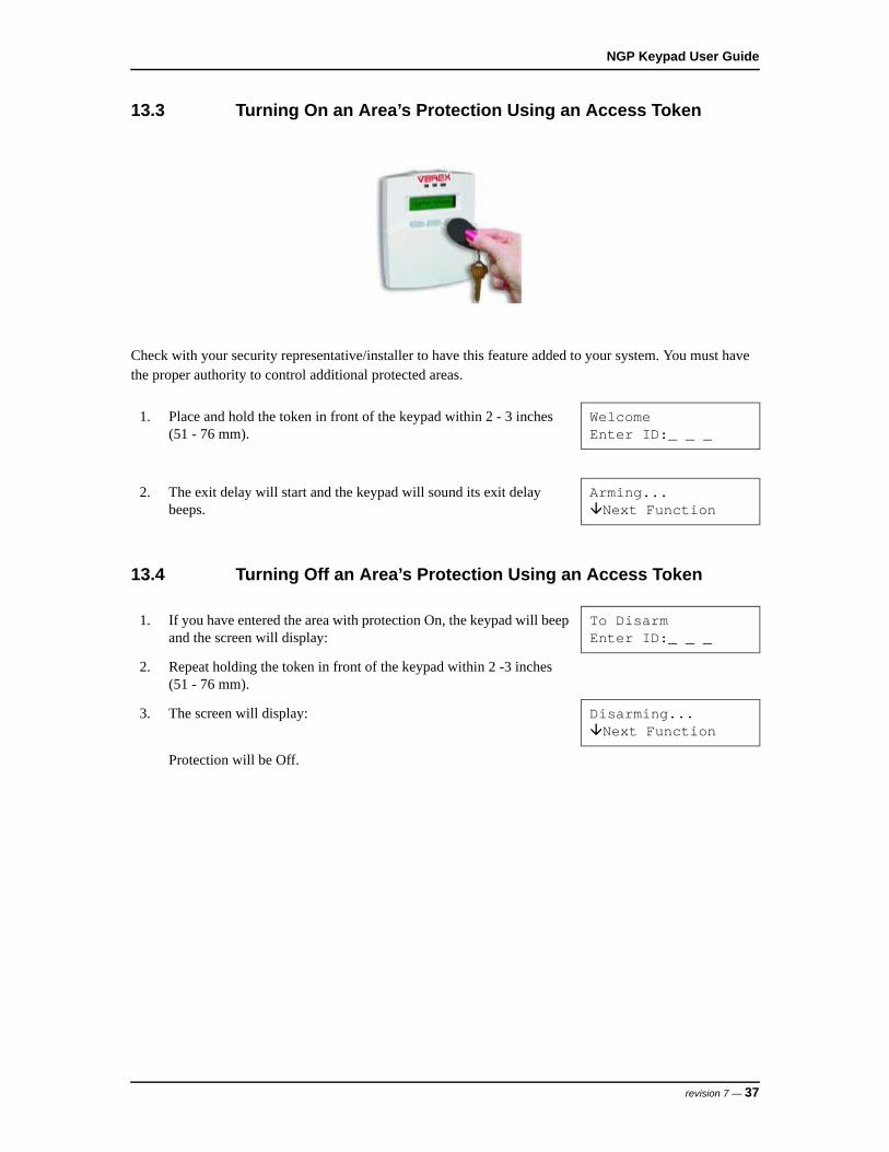
13.3 Turning On an Area’s Protection Using an Access Token
Check with your security representative/installer to have this feature added to your system. You must have the proper authority to control additional protected areas.
13.4 Turning Off an Area’s Protection Using an Access Token
1. Place and hold the token in front of the keypad within 2 - 3 inches (51 - 76 mm).
WelcomeEnter ID:_ _ _
2. The exit delay will start and the keypad will sound its exit delay beeps.
Arming...Next Function
1. If you have entered the area with protection On, the keypad will beep and the screen will display:
To DisarmEnter ID:_ _ _
2. Repeat holding the token in front of the keypad within 2 -3 inches (51 - 76 mm).
3. The screen will display: Disarming...Next Function
Protection will be Off.
revision 7 — 37

Alarms, Turning Proctection On and Off
38 — revision 7

CHECKING STATUS AND CONTROLLING ITEMS


NGP Keypad User Guide
14 Status and Control Features
Note: Status will display certain options, for example, Comms, Modem, Licns, that will not appear familiar because they are not covered in this publication. These options should be ignored by the end user because they are for a technician’s use only.
Using an LCD keypad, you can:
• Check the status of various items in the system and view the present arming-level of desired area(s).
• Bypass faulty sensors to allow arming the system and/or specific area(s).
• Command doors to unlock, relock, or change operating characteristics.
• Use the function keys to perform pre-programmed signalling and/or switching functions.
revision 7 — 41

Checking Status and Controlling Items
15 Using the Function Keys
LCD keypads provide 10 function keys that can perform various signalling and/or switching functions. Consult with your security representative/installer to learn what the ones you may have ordered do.
To use function key 1, 2, 3, 4, or 5, simply press and hold the f key, and press the desired number at the same time.
For function keys 6, 7, 8, 9, and 0, users with function-key authority may need to enter the ID/PIN to be allowed to use these function keys.
Note: This requirement can be assigned as necessary to any areas. Check with your security representative.
1. To log in, open the keypad cover and key in your user ID number and/or PIN as indicated on the display.
Welcome Enter ID: _ _ _
Your Name Appears Enter PIN: _ _ _ _
2. Then press and hold the f key and press the desired number at the same time.
42 — revision 7
NGP Keypad User Guide
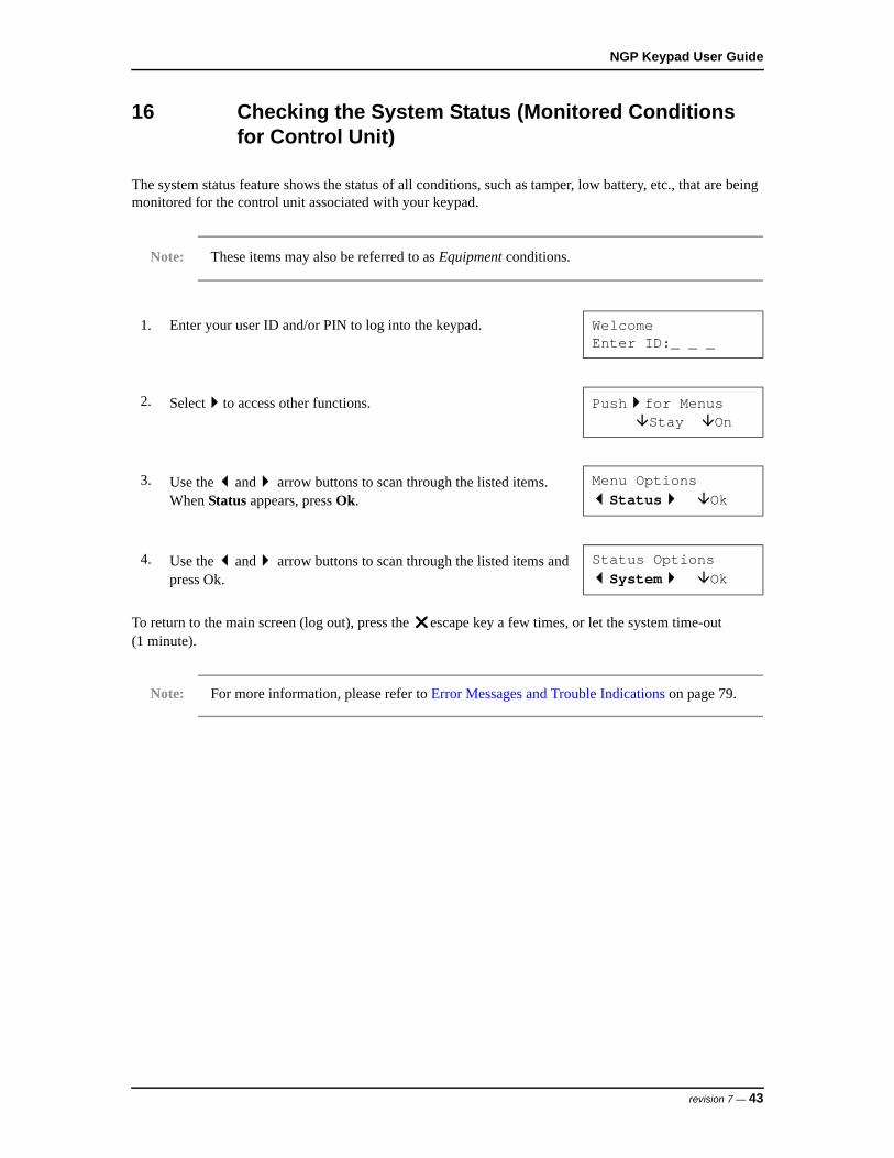
16 Checking the System Status (Monitored Conditions for Control Unit)
The system status feature shows the status of all conditions, such as tamper, low battery, etc., that are being monitored for the control unit associated with your keypad.
Note: These items may also be referred to as Equipment conditions.
To return to the main screen (log out), press the escape key a few times, or let the system time-out (1 minute).
Note: For more information, please refer to Error Messages and Trouble Indications on page 79.
1. Enter your user ID and/or PIN to log into the keypad. WelcomeEnter ID:_ _ _
2. Selectto access other functions. Pushfor MenusStay On
3. Use the and arrow buttons to scan through the listed items. When Status appears, press Ok.
Menu OptionsStatus Ok
4. Use the and arrow buttons to scan through the listed items and press Ok.
Status OptionsSystem Ok
revision 7 — 43
Checking Status and Controlling Items
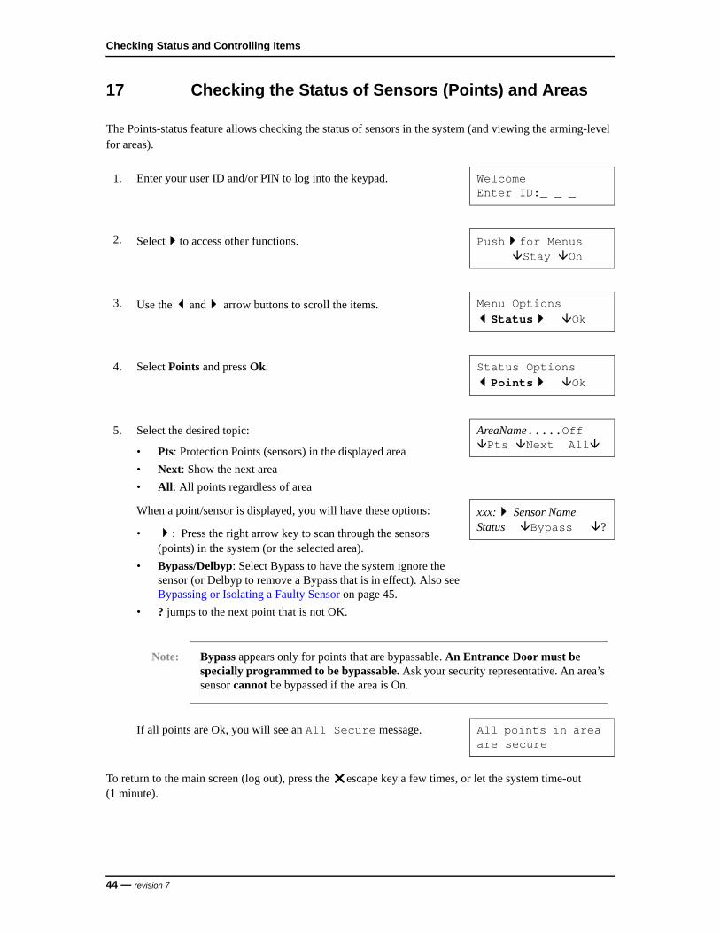
17 Checking the Status of Sensors (Points) and Areas
The Points-status feature allows checking the status of sensors in the system (and viewing the arming-level for areas).
To return to the main screen (log out), press the escape key a few times, or let the system time-out (1 minute).
1. Enter your user ID and/or PIN to log into the keypad. WelcomeEnter ID:_ _ _
2. Selectto access other functions. Pushfor MenusStay On
3. Use the and arrow buttons to scroll the items. Menu OptionsStatus Ok
4. Select Points and press Ok. Status OptionsPoints Ok
5. Select the desired topic:
• Pts: Protection Points (sensors) in the displayed area
• Next: Show the next area
• All: All points regardless of area
AreaName.....OffPts Next All
When a point/sensor is displayed, you will have these options:
• : Press the right arrow key to scan through the sensors (points) in the system (or the selected area).
• Bypass/Delbyp: Select Bypass to have the system ignore the sensor (or Delbyp to remove a Bypass that is in effect). Also see Bypassing or Isolating a Faulty Sensor on page 45.
• ? jumps to the next point that is not OK.
xxx: Sensor NameStatus Bypass ?
Note: Bypass appears only for points that are bypassable. An Entrance Door must be specially programmed to be bypassable. Ask your security representative. An area’s sensor cannot be bypassed if the area is On.
If all points are Ok, you will see an All Secure message. All points in area are secure
44 — revision 7
NGP Keypad User Guide
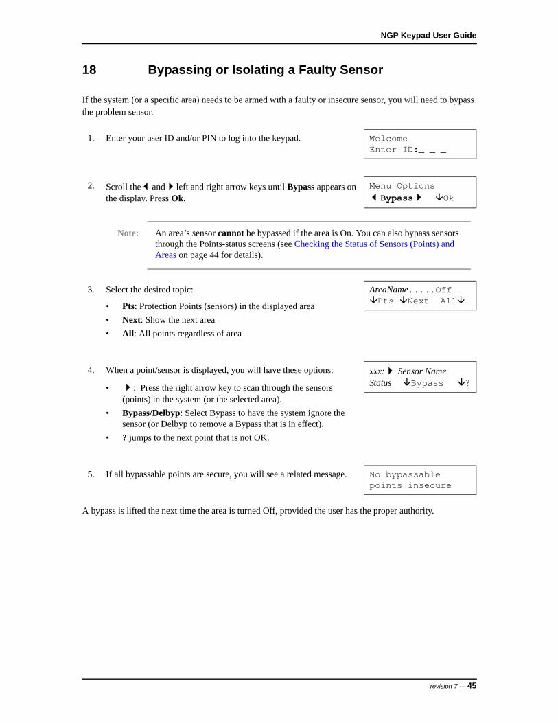
18 Bypassing or Isolating a Faulty Sensor
If the system (or a specific area) needs to be armed with a faulty or insecure sensor, you will need to bypass the problem sensor.
A bypass is lifted the next time the area is turned Off, provided the user has the proper authority.
1. Enter your user ID and/or PIN to log into the keypad. WelcomeEnter ID:_ _ _
2. Scroll theandleft and right arrow keys until Bypass appears on the display. Press Ok.
Menu OptionsBypass Ok
Note: An area’s sensor cannot be bypassed if the area is On. You can also bypass sensors through the Points-status screens (see Checking the Status of Sensors (Points) and Areas on page 44 for details).
3. Select the desired topic:
• Pts: Protection Points (sensors) in the displayed area
• Next: Show the next area
• All: All points regardless of area
AreaName.....OffPts Next All
4. When a point/sensor is displayed, you will have these options:
• : Press the right arrow key to scan through the sensors (points) in the system (or the selected area).
• Bypass/Delbyp: Select Bypass to have the system ignore the sensor (or Delbyp to remove a Bypass that is in effect).
• ? jumps to the next point that is not OK.
xxx: Sensor NameStatus Bypass ?
5. If all bypassable points are secure, you will see a related message. No bypassable points insecure
revision 7 — 45
Checking Status and Controlling Items
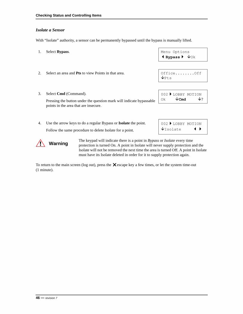
Isolate a Sensor
With “Isolate” authority, a sensor can be permanently bypassed until the bypass is manually lifted.
To return to the main screen (log out), press the escape key a few times, or let the system time-out (1 minute).
1. Select Bypass. Menu OptionsBypass Ok
2. Select an area and Pts to view Points in that area. Office........OffPts
3. Select Cmd (Command).
Pressing the button under the question mark will indicate bypassable points in the area that are insecure.
002LOBBY MOTIONOk Cmd ?
4. Use the arrow keys to do a regular Bypass or Isolate the point.
Follow the same procedure to delete Isolate for a point.
002LOBBY MOTIONIsolate
WarningThe keypad will indicate there is a point in Bypass or Isolate every time protection is turned On. A point in Isolate will never supply protection and the Isolate will not be removed the next time the area is turned Off. A point in Isolate must have its Isolate deleted in order for it to supply protection again.
46 — revision 7
NGP Keypad User Guide
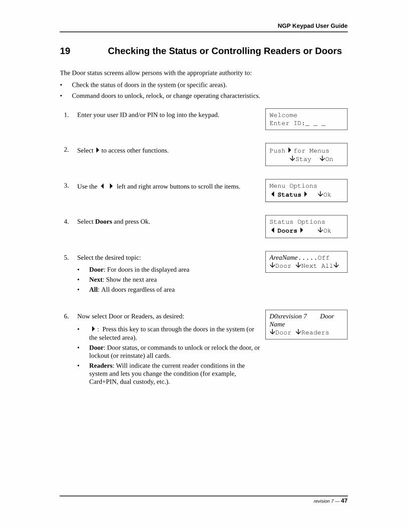
19 Checking the Status or Controlling Readers or Doors
The Door status screens allow persons with the appropriate authority to:
• Check the status of doors in the system (or specific areas).
• Command doors to unlock, relock, or change operating characteristics.
1. Enter your user ID and/or PIN to log into the keypad. WelcomeEnter ID:_ _ _
2. Selectto access other functions. Pushfor MenusStay On
3. Use the left and right arrow buttons to scroll the items. Menu OptionsStatus Ok
4. Select Doors and press Ok. Status OptionsDoors Ok
5. Select the desired topic:
• Door: For doors in the displayed area
• Next: Show the next area
• All: All doors regardless of area
AreaName.....OffDoor Next All
6. Now select Door or Readers, as desired:
• : Press this key to scan through the doors in the system (or the selected area).
• Door: Door status, or commands to unlock or relock the door, or lockout (or reinstate) all cards.
• Readers: Will indicate the current reader conditions in the system and lets you change the condition (for example, Card+PIN, dual custody, etc.).
D0xrevision 7 Door NameDoor Readers
revision 7 — 47
Checking Status and Controlling Items
To return to the main screen (log out), press the escape key a few times, or let the system time-out (1 minute).
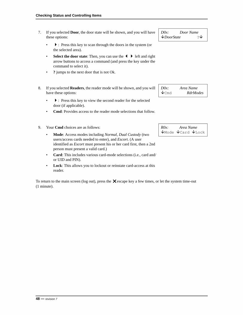
7. If you selected Door, the door state will be shown, and you will have these options:
• : Press this key to scan through the doors in the system (or the selected area).
• Select the door state: Then, you can use the left and right arrow buttons to access a command (and press the key under the command to select it).
• ? jumps to the next door that is not Ok.
D0x: Door NameDoorState ?
8. If you selected Readers, the reader mode will be shown, and you will have these options:
• : Press this key to view the second reader for the selected door (if applicable).
• Cmd: Provides access to the reader mode selections that follow.
D0x: Area NameCmd RdrModes
9. Your Cmd choices are as follows:
• Mode: Access modes including Normal, Dual Custody (two users/access cards needed to enter), and Escort. (A user identified as Escort must present his or her card first, then a 2nd person must present a valid card.)
• Card: This includes various card-mode selections (i.e., card and/or UID and PIN).
• Lock: This allows you to lockout or reinstate card-access at this reader.
R0x: Area NameMode Card Lock
48 — revision 7
NGP Keypad User Guide
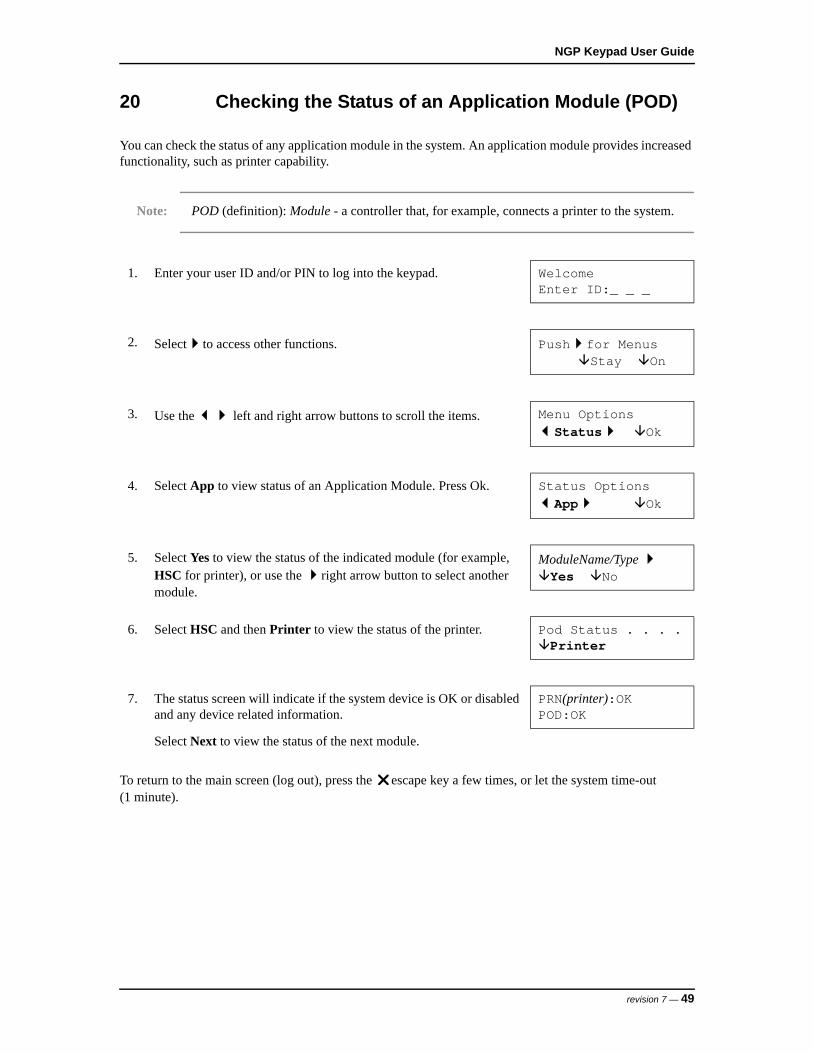
20 Checking the Status of an Application Module (POD)
You can check the status of any application module in the system. An application module provides increased functionality, such as printer capability.
Note: POD (definition): Module - a controller that, for example, connects a printer to the system.
To return to the main screen (log out), press the escape key a few times, or let the system time-out (1 minute).
1. Enter your user ID and/or PIN to log into the keypad. WelcomeEnter ID:_ _ _
2. Selectto access other functions. Pushfor MenusStay On
3. Use the left and right arrow buttons to scroll the items. Menu OptionsStatus Ok
4. Select App to view status of an Application Module. Press Ok. Status OptionsApp Ok
5. Select Yes to view the status of the indicated module (for example, HSC for printer), or use the right arrow button to select another module.
ModuleName/Type Yes No
6. Select HSC and then Printer to view the status of the printer. Pod Status . . . .Printer
7. The status screen will indicate if the system device is OK or disabled and any device related information.
PRN(printer):OKPOD:OK
Select Next to view the status of the next module.
revision 7 — 49

Checking Status and Controlling Items
21 Removing Persistent POD Status or Trouble Messages from the Keypad
POD status messages that are displayed on the NGP keypad are persistent and are only cleared when following procedure (a) or (b):
a. Log on to the NGP keypad as the Server User and then scroll through the list of messages on the Status menu item on the keypad.
– OR –
b. Log on to the NGP keypad as an NGP Panel User that has the Access service menu permission profile setting checked, and then scroll through the list of messages on the Status menu item on the keypad.
Note: The Access service menu setting is an elevated privileged setting on the NGP panel that is not configurable by default. Please contact Technical Support for assistance.
50 — revision 7

ADMINISTRATION AND MAINTENANCE TASKS


NGP Keypad User Guide
22 Changing Your Own PIN
The person who is logged in can change his or her PIN at any time.
1. Enter your user ID and/or PIN to log into the keypad. WelcomeEnter ID:_ _ _
2. Pressto scroll to the PIN option. Pushfor MenusStay On
3. Select My PIN to change your PIN, then press Ok. Menu OptionsMy Pin Ok
4. Enter your new 4-digit or 5-digit PIN. New PIN _ _ _ _ For User: UID#
Note: You can use the letters on the keypad to spell a word as a reminder of your PIN.
Re-enter the new PIN a second time when prompted (this helps to protect against typing errors).
Note: The last two digits of the PIN can not be identical. Do not use consecutive numbers such as 1234. For security reasons, duplicate PINs are not allowed on systems with a PIN only user code. If the message PIN not allowed appears, select a different PIN.
The PIN changed screen displays and then returns to the system standby screen.
PIN Changed
revision 7 — 53

Administration and Maintenance Tasks
23 Adding a User to the System
New users can be added to the system as needed.
Note: A User is a person who can use system keypads and/or gain entry at access-controlled doors.
Refer to the details that follow while working with any of the listed topics.
1. Enter your user ID and/or PIN to log into the keypad. WelcomeEnter ID:_ _ _
2. Press until Users appears and press Ok. Menu OptionsUsers Ok
3. Enter an available user number (and select OK), or select OK and then pressuntil a user number appears with Add (instead of Edit and Delete).
0xx OK Select User
4. Undfnd (Undefined) appears. Select Add. 0xx UndfndAdd
Aut: Use the Next and Prev(ious) buttons to select an authority profile for the user. (Select Ok when finished).
0xx AuthProfileOk Next Prev
Notes: The authority profile determines what doors the users can enter (and at what time of day), and the tasks they will be able to perform at system keypads. This selection cannot be Undfnd (Undefined).
Consult your security representative/installer to make changes to the authority levels.
54 — revision 7

NGP Keypad User Guide
24 Default Authority Settings
Default Authority Settings - Intrusion
Default Authority Settings - Access
Default Authority Settings Master Supervisor Employee Worker Cleaner
Emergency Off
Isolate
Bypass
Auto-lift Bypass
Test
Service Test
Silence Alarm
Status
History
Function Key Authorization
Worklate
Suspend Schedule
On
Off
Stay
Auto Disarm to Off
Auto Disarm all Areas
Default Authority Settings Master Supervisor Employee Worker Cleaner
Access when Area is Off/On/Stay
Escort
Master Override
Reset Door Alarm
Door Command
revision 7 — 55

Administration and Maintenance Tasks
To return to the main screen (log out), press the escape key a few times, or let the system time-out (1 minute).
More: Provides access to additional screens.
Name: Use the keypad to enter the user’s name, and select OK when finished.
_ . . . .OK
Notes: Check the letters on the numeric keypad. Then, for each letter of the name, press the specific key until the letter appears (for example, pressing 2 makes a 2, A, B, C; 0 provides 0, Z, _ <space>, Q, etc.).
To move to the next letter-position, use theright arrow button, or wait two (2) seconds. To
retype a previous letter, use theleft or right arrow keys, and then enter the letter as before.
Card: Enter the card version number (if applicable) and the access-card/token number for this user. Select OK when finished.
0xx UserNameOK vv_nnnnnnnnn
Notes: If card-access (entry at controlled doors) does not apply, leave the card number as 000000000.
Card Version number support is supplied by your security representative.
Firmware revisions needed for 9-digit card IDs or cards with version numbers: Panel firmware V3.2, and door controller firmware V1.5.
PIN: Allows setting or changing the Personal ID Number for this user. (You will be asked to enter it twice to help protect against typing errors.)
New PIN - - - -For User 0xx
Note: The last two digits of the PIN must be different. Do not use consecutive numbers like 1234.
Lang/Chal: This screen allows setting the LCD language for this user, and whether or not the physically-challenged unlock times and door-held-open times apply to this user. Select Lang to toggle the language, or Chal to toggle the Challenged setting. When finished, select OK.
0xx..Lng:Eng.C:NOK Lang Chal
Notes: Watch the screen for the settings to change. (You will remain in this same screen.)
Lng:Eng means Language is EnglishC:N means Challenged? - No.
56 — revision 7
NGP Keypad User Guide
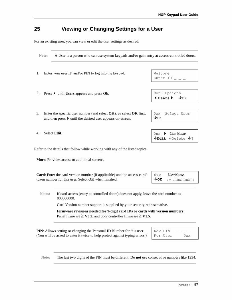
25 Viewing or Changing Settings for a User
For an existing user, you can view or edit the user settings as desired.
Note: A User is a person who can use system keypads and/or gain entry at access-controlled doors.
Refer to the details that follow while working with any of the listed topics.
1. Enter your user ID and/or PIN to log into the keypad. WelcomeEnter ID:_ _ _
2. Press until Users appears and press Ok. Menu OptionsUsers Ok
3. Enter the specific user number (and select OK), or select OK first, and then pressuntil the desired user appears on-screen.
0xx Select UserOK
4. Select Edit. 0xx UserNameEdit Delete ?
More: Provides access to additional screens.
Card: Enter the card version number (if applicable) and the access-card/token number for this user. Select OK when finished.
0xx UserNameOK vv_nnnnnnnnn
Notes: If card-access (entry at controlled doors) does not apply, leave the card number as 000000000.
Card Version number support is supplied by your security representative.
Firmware revisions needed for 9-digit card IDs or cards with version numbers: Panel firmware V3.2, and door controller firmware V1.5.
PIN: Allows setting or changing the Personal ID Number for this user. (You will be asked to enter it twice to help protect against typing errors.)
New PIN - - - -For User 0xx
Note: The last two digits of the PIN must be different. Do not use consecutive numbers like 1234.
revision 7 — 57

Administration and Maintenance Tasks
To return to the main screen (log out), press the escape key a few times, or let the system time-out (1 minute).
Name: Use the keypad to enter the user’s name and select OK when finished.
UserName . . . .OK
Notes: Check the letters on the numeric keypad. Then, for each letter of the name, press the specific key until the letter appears (for example, pressing 2 makes a 2, A, B, C; 0 provides 0, Z, _ <space>, Q, etc.).
To move to the next letter-position, use theright arrow button, or wait two (2) seconds. To
retype a previous letter, use theleft or right arrow keys, and then enter the letter as before.
Aut: Use the Next and Prev(ious) buttons to select an authority profile for the user. (Select Ok when finished).
0xx AuthProfileOk Next Prev
Notes: The authority profile determines what doors the users can enter (and at what time of day), and the tasks they will be able to perform at system keypads. This selection cannot be Undfnd (Undefined).
Consult your security representative/installer to make changes to the authority levels.
Lang/Chal: This screen allows setting the LCD language for this user, and whether or not the physically-challenged unlock times and door-held-open times apply to this user. Select Lang to toggle the language, or Chal to toggle the Challenged setting. When finished, select OK.
0xx..Lng:Eng.C:NOK Lang Chal
Note: Watch the screen for the settings to change. (You will remain in this same screen.)
58 — revision 7

NGP Keypad User Guide
26 Deleting a User
Users can be deleted from the system when necessary.
Notes: To allow tracking card-usage, you can alternatively leave the users in the system, but set them to an authority profile that provides no access to doors or keypads. (For more information, please refer to Viewing or Changing Settings for a User on page 57.)
Setting the authority to undefined will delete the user (equivalent to selecting Delete).
To return to the main screen (log out), press the escape key a few times, or let the system time-out (1 minute).
1. Enter your user ID and/or PIN to log into the keypad. WelcomeEnter ID:_ _ _
2. Use theleft and right arrow buttons to scroll the items until Users appears and press Ok.
Menu OptionsUsers Ok
3. Enter the specific user number (and select OK), or select OK first, and then pressuntil the desired user appears on-screen.
0xx Select UserOK
4. With the desired user on-screen, select Delete. 0xx UserNameEdit Delete ?
5. Then, select Yes to delete the user, or Cancel to stop the action. Del?Yes Cancel
revision 7 — 59
Administration and Maintenance Tasks
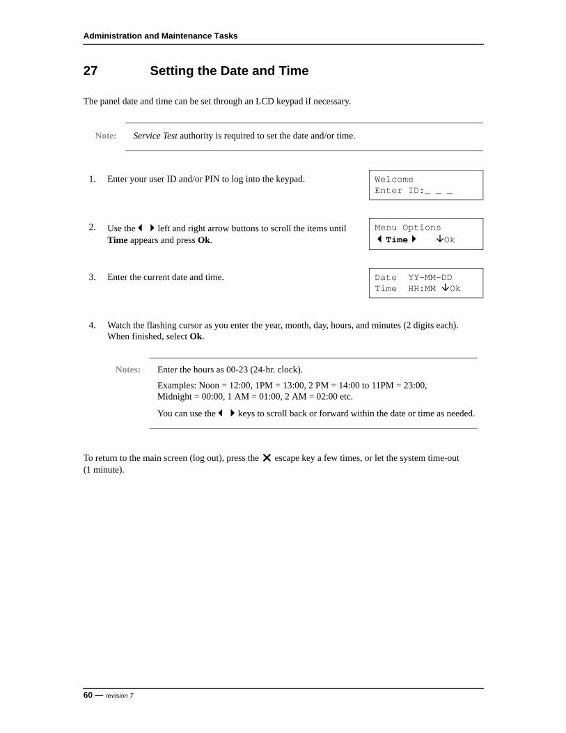
27 Setting the Date and Time
The panel date and time can be set through an LCD keypad if necessary.
Note: Service Test authority is required to set the date and/or time.
To return to the main screen (log out), press the escape key a few times, or let the system time-out (1 minute).
1. Enter your user ID and/or PIN to log into the keypad. WelcomeEnter ID:_ _ _
2. Use theleft and right arrow buttons to scroll the items until Time appears and press Ok.
Menu OptionsTime Ok
3. Enter the current date and time. Date YY-MM-DDTime HH:MM Ok
4. Watch the flashing cursor as you enter the year, month, day, hours, and minutes (2 digits each). When finished, select Ok.
Notes: Enter the hours as 00-23 (24-hr. clock).
Examples: Noon = 12:00, 1PM = 13:00, 2 PM = 14:00 to 11PM = 23:00, Midnight = 00:00, 1 AM = 01:00, 2 AM = 02:00 etc.
You can use thekeys to scroll back or forward within the date or time as needed.
60 — revision 7

NGP Keypad User Guide
28 Viewing the History
All activity that occurs in the system can be viewed one event at a time. This includes area (alarms)/door activity, as well as the tasks that users have performed at a keypad.
Note: Depending on your system type and licensing permissions, up to 65,536 events will be recorded. Viewing an area’s history requires authority for that area.
To return to the main screen (log out), press the escape key a few times, or let the system time-out (1 minute).
1. Enter your user ID and/or PIN to log into the keypad. WelcomeEnter ID:_ _ _
2. Use theleft and right arrow buttons to scroll the items until History appears and press Ok.
Menu OptionsHistory Ok
3. Select All for a complete list, or Category for history referring to an Area, keypad, or Application module (e.g., printer). Press Ok.
View History of:All Ok
4. If you selected Category, select your desired topic (such as by Area).
Note: If you selected All, the area or other items associated with each event will be shown on the screen.
View History of:Area Condo App
5. If you selected by Area, the arming-level for the first area will be shown, and you can select:
• Hist: Shows the log of events for the displayed area.
• Next Area: Jumps to the next area.
AreaName .....OffHist Next Area
6. To cycle through the History, press the left or right arrow keys. For more details about this event select . . . .
Notes: Press any of these keys to continue viewing the History.
T/L next to the time indicates that the date/time had not been set when the event occurred.
xxx 1:23pMarEvent Displays ...
revision 7 — 61
Administration and Maintenance Tasks
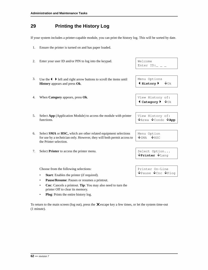
29 Printing the History Log
If your system includes a printer-capable module, you can print the history log. This will be sorted by date.
To return to the main screen (log out), press the escape key a few times, or let the system time-out (1 minute).
1. Ensure the printer is turned on and has paper loaded.
2. Enter your user ID and/or PIN to log into the keypad. WelcomeEnter ID:_ _ _
3. Use theleft and right arrow buttons to scroll the items until History appears and press Ok.
Menu OptionsHistory Ok
4. When Category appears, press Ok. View History of:Category Ok
5. Select App (Application Module) to access the module with printer functions.
View History of:Area Condo App
6. Select SMA or HSC, which are other related equipment selections for use by a technician only. However, they will both permit access to the Printer selection.
Menu OptionSMA HSC
7. Select Printer to access the printer menu. Select Option...Printer Lang
Choose from the following selections:
• Start: Enables the printer (if required).
• Pause/Resume: Pauses or resumes a printout.
• Cnc: Cancels a printout. Tip: You may also need to turn the printer Off to clear its memory.
• Plog: Prints the entire history log.
Printer On-LinePause Cnc Plog
62 — revision 7

NGP Keypad User Guide
30 Changing the Printed History Language
You can change the language for the printed history log when needed.
Note: Check with your security representative/installer to confirm your system version is capable of this feature.
Follow steps 1 to 6 from the procedure Printing the History Log on page 62.
To return to the main screen (log out), press the escape key a few times, or let the system time-out (1 minute).
7. At step 7, select Lang to change the printing language for this application module.
Select Option...Printer Lang
Note: The present printed language will be indicated on the first line next to Lang:.
8. Select Change to change the language. Press Ok when completed. Lang: LanguageOk Change
revision 7 — 63

Administration and Maintenance Tasks
31 Testing Monitored Sensors (Performing a Walk Test)
A Walk Test allows you to test specific sensors (protection points) in the system to ensure that they are functioning properly.
Notes: A Walk Test can be done by users with System Test authority.
A Walk Test must be completed within 15 minutes.
Emergency points (i.e., smoke, fire alarm, panic, etc.) on a Monitored system display as Armed and should not be tested during a Walk Test. The monitoring station must be notified if these points will be tested.
Fire sensors must be tested once per week for UL listed systems.
When tested successfully, Emergency points will indicate Pass and Armed will change to Alarm.
Pass indicates that an intrusion point is functioning correctly (that is, the sensor is operating properly), while Fail indicates that a problem may exist with that point or that the point was not tripped.
All points, except Emergency points, may be bypassed during the Review for convenience. Restore any bypassed points before turning protection On, or they will reduce system security.
1. Enter your user ID and/or PIN to log into the keypad. WelcomeEnter ID:_ _ _
2. Use theleft and right arrow buttons to scroll the items until Test appears and press Ok.
Menu OptionsTest Ok
3. When Area appears, press Ok. Test?Area System
4. Choose from the following selections:
• Test: To test the displayed area.
• Next Area: To jump to the next area.
AreaName .....OffTest Next Area
5. Select Walk to perform a Walk Test of this area. Select test typeWalk Holdup
64 — revision 7

NGP Keypad User Guide
To return to the main screen (log out), press the escape key a few times, or let the system time-out (1 minute).
6. At this time you can proceed to test the protection points in the selected area (i.e., open doors, walk in front of motion detectors, etc.).
Notes: If any fire sensors or 24-hour type inputs must be tested and it is a reporting system, the monitoring station must be notified.
The Walk Test must be completed within 15 minutes.
7. After activating points in the tested area, return to the keypad and select Review to view the results of the Walk Test.
Area in walk testReview End
8. The tested points and the results (Pass/Fail) will be displayed. xxx ItemNameStatus ...
9. Press the . . . key to view all points that passed during the test. Another method is to use the left and right arrow buttons to scroll through the results of all points tested in the area.
revision 7 — 65
Administration and Maintenance Tasks
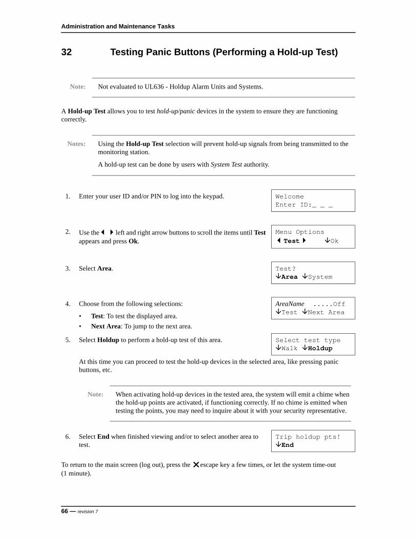
32 Testing Panic Buttons (Performing a Hold-up Test)
Note: Not evaluated to UL636 - Holdup Alarm Units and Systems.
A Hold-up Test allows you to test hold-up/panic devices in the system to ensure they are functioning correctly.
Notes: Using the Hold-up Test selection will prevent hold-up signals from being transmitted to the monitoring station.
A hold-up test can be done by users with System Test authority.
To return to the main screen (log out), press the escape key a few times, or let the system time-out (1 minute).
1. Enter your user ID and/or PIN to log into the keypad. WelcomeEnter ID:_ _ _
2. Use theleft and right arrow buttons to scroll the items until Test appears and press Ok.
Menu OptionsTest Ok
3. Select Area. Test?Area System
4. Choose from the following selections:
• Test: To test the displayed area.
• Next Area: To jump to the next area.
AreaName .....OffTest Next Area
5. Select Holdup to perform a hold-up test of this area. Select test typeWalk Holdup
At this time you can proceed to test the hold-up devices in the selected area, like pressing panic buttons, etc.
Note: When activating hold-up devices in the tested area, the system will emit a chime when the hold-up points are activated, if functioning correctly. If no chime is emitted when testing the points, you may need to inquire about it with your security representative.
6. Select End when finished viewing and/or to select another area to test.
Trip holdup pts!End
66 — revision 7
NGP Keypad User Guide
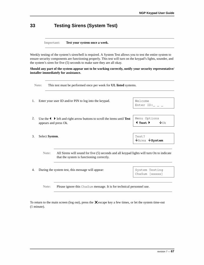
33 Testing Sirens (System Test)
Important: Test your system once a week.
Weekly testing of the system’s siren/bell is required. A System Test allows you to test the entire system to ensure security components are functioning properly. This test will turn on the keypad’s lights, sounder, and the system’s siren for five (5) seconds to make sure they are all okay.
Should any part of the system appear not to be working correctly, notify your security representative/installer immediately for assistance.
Note: This test must be performed once per week for UL listed systems.
To return to the main screen (log out), press the escape key a few times, or let the system time-out (1 minute).
1. Enter your user ID and/or PIN to log into the keypad. WelcomeEnter ID:_ _ _
2. Use theleft and right arrow buttons to scroll the items until Test appears and press Ok.
Menu OptionsTest Ok
3. Select System. Test?Area System
Note: All Sirens will sound for five (5) seconds and all keypad lights will turn On to indicate that the system is functioning correctly.
4. During the system test, this message will appear: System TestingChxSum [xxxxx]
Note: Please ignore this ChxSum message. It is for technical personnel use.
revision 7 — 67

Administration and Maintenance Tasks
68 — revision 7

REFERENCE TOPICS

NGP Keypad User Guide
34 System Information
Your alarm system has specific information. This information should be recorded below at the time of your system’s installation.
34.1 Contact Information
Security Representative:
___________________________________
___________________________________
___________________________________
Monitoring Station Phone Number:
___________________________________
Your System Number:
___________________________________
When to Contact the Monitoring Station
• When an accidental alarm happens.
• When major work is being done on the premises that could interfere with the alarm.
• If you lose your system number and password.
• When doing a periodic test that may involve testing panic buttons, some sensors, or with all the protection turned On.
When to Contact your Security Representative
• If there appears to be a fault with the system.
• To order additional protection equipment for installation, such as a contact for a new door, smoke sensors, motion detector for a new room addition, etc.
Protected Area Names:
Area 1:_____________________________
Area 2:_____________________________
Area 3:_____________________________
Area 4:_____________________________
Area 5:_____________________________
revision 7 — 71

Reference Topics
Area 6:_____________________________
Area 7:_____________________________
Area 8:_____________________________
Area 9:_____________________________
Area 10:_____________________________
Area 11:_____________________________
Area 12:_____________________________
Area 13:_____________________________
Area 14:_____________________________
Area 15:_____________________________
Area 16:_____________________________
34.2 System Details
Entry and Exit Delays:
Entry Delay:_______ Exit Delay:_______
Miscellaneous Features:
Emergency Keys that are Available:
Yes No
Duress PIN entry supported
Entry Delay in Stay
Arm to Stay if Failure to Exit
Terminate Exit Delay
Alarm if Failure to Exit
Yes No
Fire
Police
Emergency (non medical)
72 — revision 7
NGP Keypad User Guide
34.3 Function Key Reference
The Function key f is pressed and held in while pressing specific number keys for customized functions.
Note: Function keys are not active until they have been added to the system by your security representative.
Function keys 1 - 5 can be used by anyone. Function keys 6, 7, 8, 9 and 0 may require users (with function key authority) to enter their user numbers before they can operate the function keys.
Function Key Assignments:
f + 1 = _________________________
f + 2 = _________________________
f + 3 = _________________________
f + 4 = _________________________
f + 5 = _________________________
(also turns chime On and Off)
f + 6 = _________________________
f + 7 = _________________________
f + 8 = _________________________
f + 9 = _________________________
f + 0 = _________________________
Door Chime Feature
The Door Chime feature refers to LCD keypads emitting tones when a perimeter door is opened to alert the person(s) inside that someone has entered. This feature can be used when the system is turned off or while it is in perimeter protection (doors only), referred to as Stay. The system has to be programmed for Allow User Entry at the Front Door in Stay by the installer.
Pressing keypad keys f and 5 simultaneously always toggles the chime feature on and off. This function key sequence can also be programmed for an additional function that can turn on or off when the chime is turned on or off.
revision 7 — 73
Reference Topics
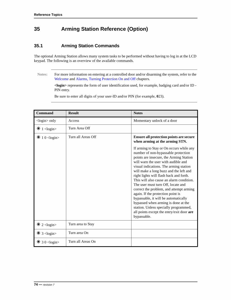
35 Arming Station Reference (Option)
35.1 Arming Station Commands
The optional Arming Station allows many system tasks to be performed without having to log in at the LCD keypad. The following is an overview of the available commands.
Notes: For more information on entering at a controlled door and/or disarming the system, refer to the Welcome and Alarms, Turning Protection On and Off chapters.
<login> represents the form of user identification used, for example, badging card and/or ID - PIN entry.
Be sure to enter all digits of your user-ID and/or PIN (for example, 023).
Command Result Notes
<login> only Access Momentary unlock of a door
1 <login> Turn Area Off
1 0 <login> Turn all Areas Off Ensure all protection points are secure when arming at the arming STN.
If arming to Stay or On occurs while any number of non-bypassable protection points are insecure, the Arming Station will warn the user with audible and visual indications. The arming station will make a long buzz and the left and right lights will flash back and forth. This will also cause an alarm condition. The user must turn Off, locate and correct the problem, and attempt arming again. If the protection point is bypassable, it will be automatically bypassed when arming is done at the station. Unless specially programmed, all points except the entry/exit door are bypassable.
2 <login> Turn area to Stay
3 <login> Turn area On
3 0 <login> Turn all Areas On
74 — revision 7
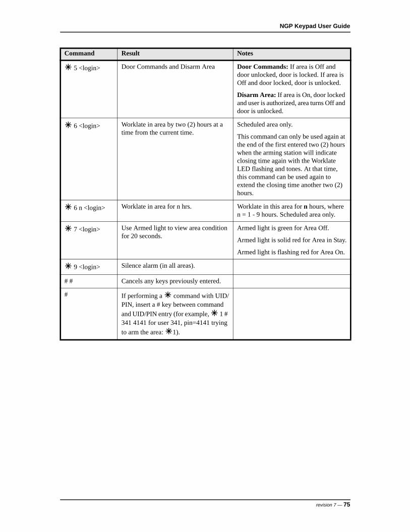
NGP Keypad User Guide
5 <login> Door Commands and Disarm Area Door Commands: If area is Off and door unlocked, door is locked. If area is Off and door locked, door is unlocked.
Disarm Area: If area is On, door locked and user is authorized, area turns Off and door is unlocked.
6 <login> Worklate in area by two (2) hours at a time from the current time.
Scheduled area only.
This command can only be used again at the end of the first entered two (2) hours when the arming station will indicate closing time again with the Worklate LED flashing and tones. At that time, this command can be used again to extend the closing time another two (2) hours.
6 n <login> Worklate in area for n hrs. Worklate in this area for n hours, where n = 1 - 9 hours. Scheduled area only.
7 <login> Use Armed light to view area condition for 20 seconds.
Armed light is green for Area Off.
Armed light is solid red for Area in Stay.
Armed light is flashing red for Area On.
9 <login> Silence alarm (in all areas).
# # Cancels any keys previously entered.
# If performing a command with UID/PIN, insert a # key between command
and UID/PIN entry (for example, 1 # 341 4141 for user 341, pin=4141 trying
to arm the area: 1).
Command Result Notes
revision 7 — 75
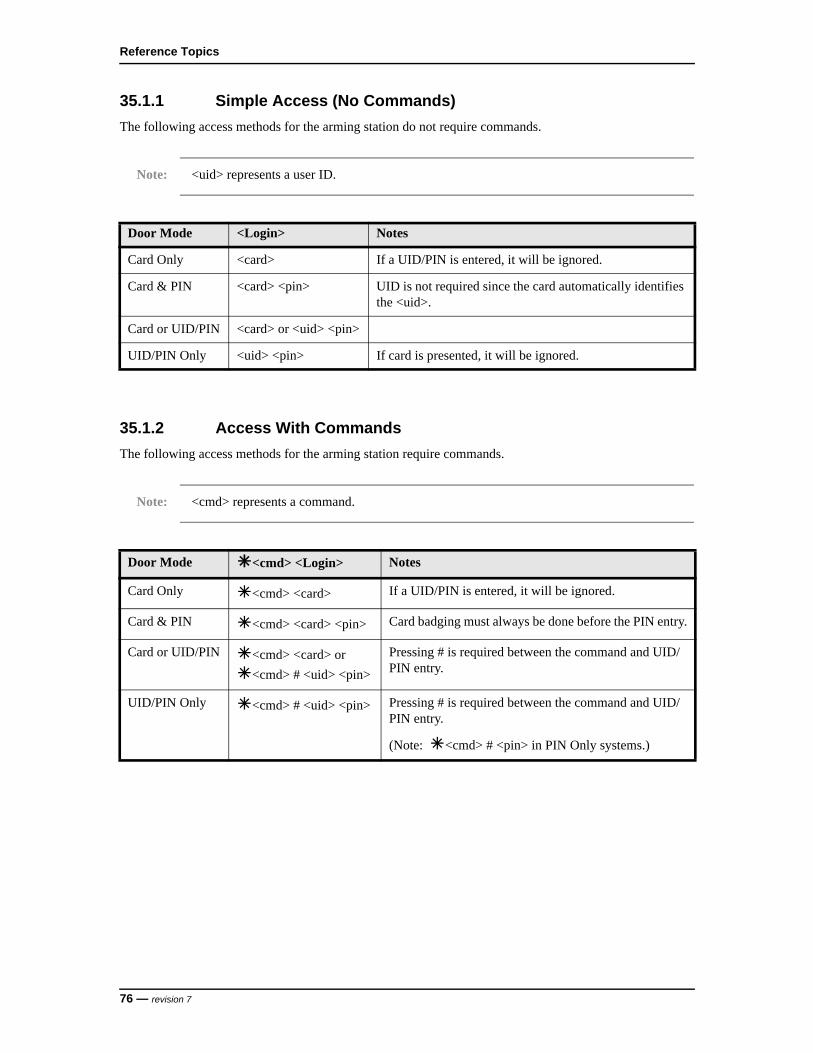
Reference Topics
35.1.1 Simple Access (No Commands)
The following access methods for the arming station do not require commands.
Note: <uid> represents a user ID.
35.1.2 Access With Commands
The following access methods for the arming station require commands.
Note: <cmd> represents a command.
Door Mode <Login> Notes
Card Only <card> If a UID/PIN is entered, it will be ignored.
Card & PIN <card> <pin> UID is not required since the card automatically identifies the <uid>.
Card or UID/PIN <card> or <uid> <pin>
UID/PIN Only <uid> <pin> If card is presented, it will be ignored.
Door Mode <cmd> <Login> Notes
Card Only <cmd> <card> If a UID/PIN is entered, it will be ignored.
Card & PIN <cmd> <card> <pin> Card badging must always be done before the PIN entry.
Card or UID/PIN <cmd> <card> or
<cmd> # <uid> <pin>
Pressing # is required between the command and UID/PIN entry.
UID/PIN Only <cmd> # <uid> <pin> Pressing # is required between the command and UID/PIN entry.
(Note: <cmd> # <pin> in PIN Only systems.)
76 — revision 7

NGP Keypad User Guide
35.2 Arming Station Lights and Tones/Sirens
The optional NGP Arming Station has three lights to indicate door, system, and arming status. The following list indicates the light messages and audible results from the Arming Station. For detailed information on keypad tones, see Audible Keypad Tones on page 25.
1. Arming Station Lights
2. The icon on key 9 is for the command to silence an alarm: 9 <login>
Arming Station Lights
Worklate LightYellow light On solid within 15 minutes of the scheduled closing time. Off if the area is not scheduled, or there are more than 15 minutes to the scheduled closing time.
Door State LightRed light On solid if the door is locked. Same light solid green if the door is unlocked. Flashing red while protection turning Off if there was an alarm in the area.
Armed LightOn solid green if the area is disarmed (Off). On solid red if the area is set to the Stay arming-level (only the perimeter sensors being monitored). Flashing red if the area is armed (On).
revision 7 — 77
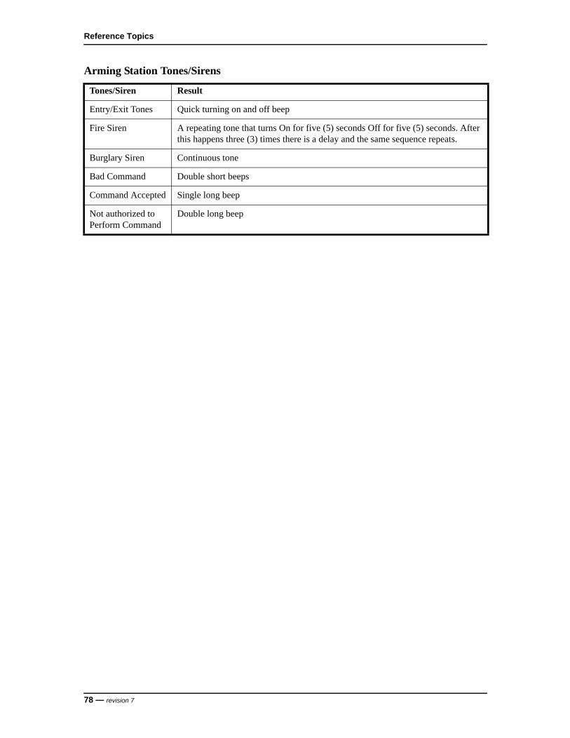
Reference Topics
Arming Station Tones/Sirens
Tones/Siren Result
Entry/Exit Tones Quick turning on and off beep
Fire Siren A repeating tone that turns On for five (5) seconds Off for five (5) seconds. After this happens three (3) times there is a delay and the same sequence repeats.
Burglary Siren Continuous tone
Bad Command Double short beeps
Command Accepted Single long beep
Not authorized to Perform Command
Double long beep
78 — revision 7

NGP Keypad User Guide
36 Error Messages and Trouble Indications
36.1 Keypad Screen Display Error Messages
This section contains a list of error messages that may appear on the keypad’s display screen. The condition responsible for each message is explained below.
Note: If a trouble condition persists, contact your security representative/installer to investigate.
36.2 Keypad Yellow Trouble Light
The Yellow Trouble Light on the keypad may turn On when the following system conditions occur:
System Tamper, Battery Trouble, AC Failure (Flashing), Phone Line Trouble, Report Delay, Time Lost, Time Changed, Program Error, Fuse Trouble, Module Trouble, Module Program Error, Misc. (Test Failure), HSC Trouble, Fire Circuit Faults.
36.3 System Status Trouble
The following conditions may appear when viewing the system status:
• System Tamper
• LoNoBattery
• AC Failure
• No PhoneLine
• Report Delay
Error Message Error Condition
Power Failure AC Failure
System Trouble Control Unit or Module Tamper condition, module Communications failure, Fuse Failure, Fire Circuit Faults
Battery Trouble Low voltage from Control Unit or module battery or missing/disconnected
Phone Trouble Trouble with Communications to the monitoring station
Report Trouble Trouble with Communications to the monitoring station
Area in Test Walk Test or Hold-up Test in-progress
Program Lost Alarm System Operations Configuration lost
Program Error Error in Alarm System Configuration on Control Unit, Error in Configuration on module
HSC Comms Alarm Communications Trouble
revision 7 — 79
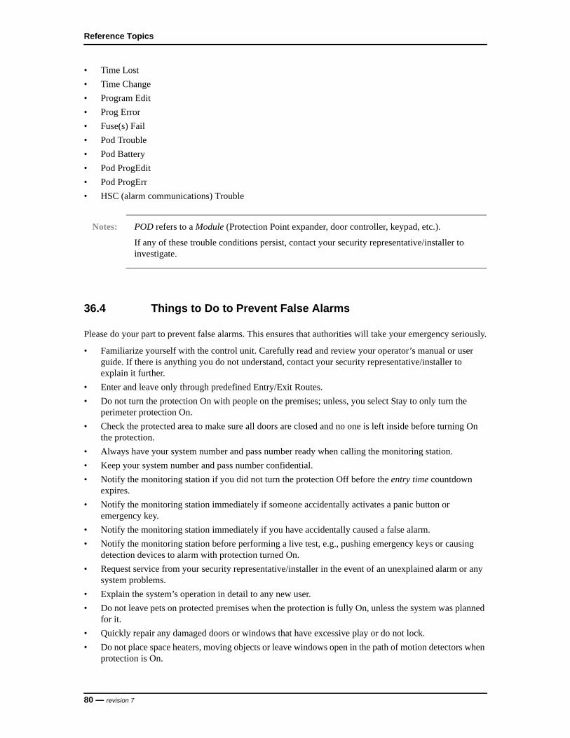
Reference Topics
• Time Lost
• Time Change
• Program Edit
• Prog Error
• Fuse(s) Fail
• Pod Trouble
• Pod Battery
• Pod ProgEdit
• Pod ProgErr
• HSC (alarm communications) Trouble
Notes: POD refers to a Module (Protection Point expander, door controller, keypad, etc.).
If any of these trouble conditions persist, contact your security representative/installer to investigate.
36.4 Things to Do to Prevent False Alarms
Please do your part to prevent false alarms. This ensures that authorities will take your emergency seriously.
• Familiarize yourself with the control unit. Carefully read and review your operator’s manual or user guide. If there is anything you do not understand, contact your security representative/installer to explain it further.
• Enter and leave only through predefined Entry/Exit Routes.
• Do not turn the protection On with people on the premises; unless, you select Stay to only turn the perimeter protection On.
• Check the protected area to make sure all doors are closed and no one is left inside before turning On the protection.
• Always have your system number and pass number ready when calling the monitoring station.
• Keep your system number and pass number confidential.
• Notify the monitoring station if you did not turn the protection Off before the entry time countdown expires.
• Notify the monitoring station immediately if someone accidentally activates a panic button or emergency key.
• Notify the monitoring station immediately if you have accidentally caused a false alarm.
• Notify the monitoring station before performing a live test, e.g., pushing emergency keys or causing detection devices to alarm with protection turned On.
• Request service from your security representative/installer in the event of an unexplained alarm or any system problems.
• Explain the system’s operation in detail to any new user.
• Do not leave pets on protected premises when the protection is fully On, unless the system was planned for it.
• Quickly repair any damaged doors or windows that have excessive play or do not lock.
• Do not place space heaters, moving objects or leave windows open in the path of motion detectors when protection is On.
80 — revision 7
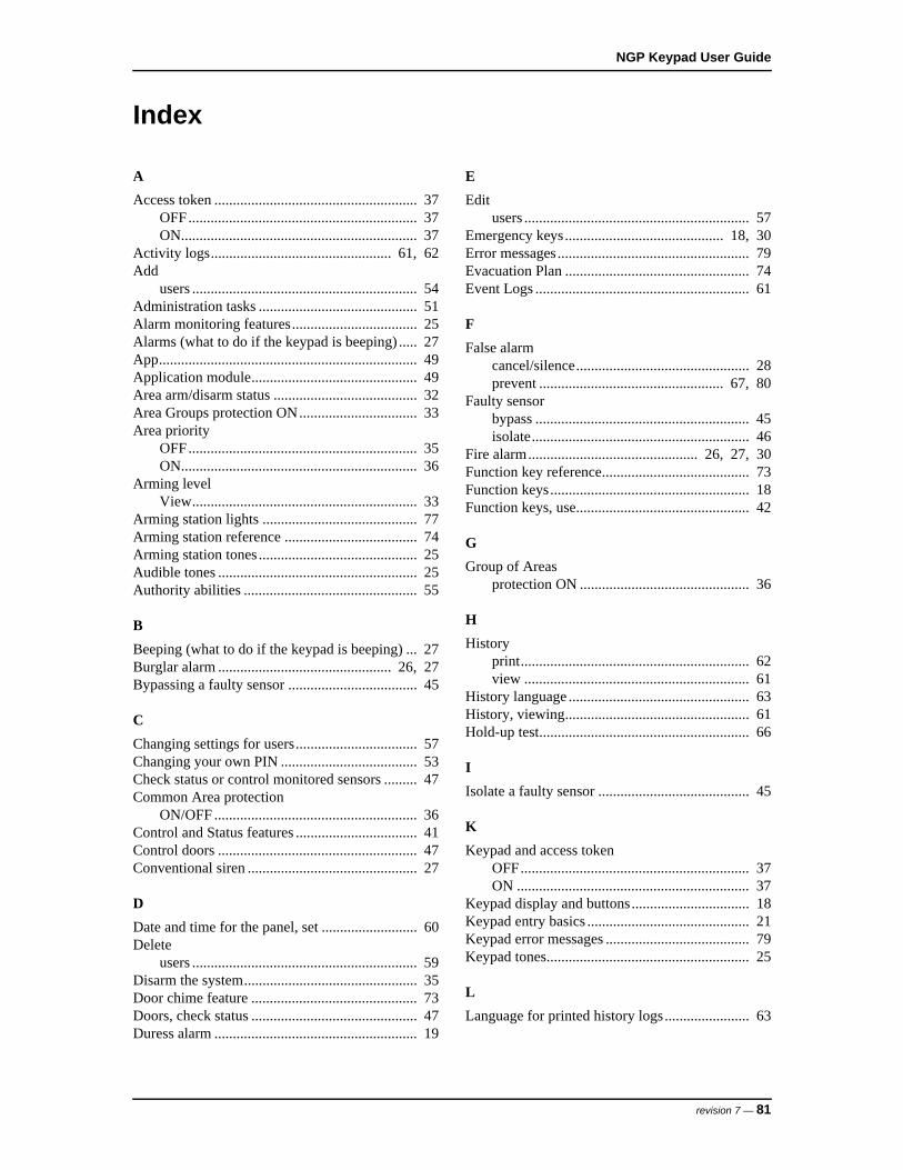
NGP Keypad User Guide
Index
A
Access token ....................................................... 37OFF.............................................................. 37ON................................................................ 37
Activity logs................................................. 61, 62Add
users ............................................................. 54Administration tasks ........................................... 51Alarm monitoring features.................................. 25Alarms (what to do if the keypad is beeping) ..... 27App...................................................................... 49Application module............................................. 49Area arm/disarm status ....................................... 32Area Groups protection ON................................ 33Area priority
OFF.............................................................. 35ON................................................................ 36
Arming levelView............................................................. 33
Arming station lights .......................................... 77Arming station reference .................................... 74Arming station tones ........................................... 25Audible tones ...................................................... 25Authority abilities ............................................... 55
B
Beeping (what to do if the keypad is beeping) ... 27Burglar alarm ............................................... 26, 27Bypassing a faulty sensor ................................... 45
C
Changing settings for users................................. 57Changing your own PIN ..................................... 53Check status or control monitored sensors ......... 47Common Area protection
ON/OFF ....................................................... 36Control and Status features ................................. 41Control doors ...................................................... 47Conventional siren .............................................. 27
D
Date and time for the panel, set .......................... 60Delete
users ............................................................. 59Disarm the system............................................... 35Door chime feature ............................................. 73Doors, check status ............................................. 47Duress alarm ....................................................... 19
E
Editusers ............................................................. 57
Emergency keys........................................... 18, 30Error messages.................................................... 79Evacuation Plan .................................................. 74Event Logs .......................................................... 61
F
False alarmcancel/silence............................................... 28prevent .................................................. 67, 80
Faulty sensorbypass .......................................................... 45isolate........................................................... 46
Fire alarm.............................................. 26, 27, 30Function key reference........................................ 73Function keys...................................................... 18Function keys, use............................................... 42
G
Group of Areasprotection ON .............................................. 36
H
Historyprint.............................................................. 62view ............................................................. 61
History language ................................................. 63History, viewing.................................................. 61Hold-up test......................................................... 66
I
Isolate a faulty sensor ......................................... 45
K
Keypad and access tokenOFF.............................................................. 37ON ............................................................... 37
Keypad display and buttons................................ 18Keypad entry basics ............................................ 21Keypad error messages ....................................... 79Keypad tones....................................................... 25
L
Language for printed history logs....................... 63
revision 7 — 81
Index
M
Maintenance tasks............................................... 51Monitoring Station, when to contact................... 71
O
OFF, protection ................................................... 35ON, protection .................................................... 33ON, protection by Area Groups .......................... 36
P
Panic buttonstest................................................................ 66
PIN ...................................................................... 19add 1 to last digit to indicate duress............. 19change .......................................................... 53
POD .................................................................... 49Points (sensors)
bypass or isolate........................................... 45check status.................................................. 44
Print the history log............................................. 62Printer.................................................................. 49Priority arming.................................................... 36Protection
OFF.............................................................. 35ON................................................................ 36ON, STAY ................................................... 33
R
Readers, checking status or controlling .............. 47Relock doors ....................................................... 47
S
Scheduleblock ............................................................ 32extend........................................................... 31suspend ........................................................ 32
Security Representative, when to contact ........... 71Sensors
bypass or isolate........................................... 45check status.................................................. 44
Setate and time for the panel............................. 60
Set date and time................................................. 60Sirens .................................................................. 27
test................................................................ 67STAY, protection................................................ 33System test .......................................................... 67
T
Testsirens ............................................................ 67
Test the system
panic buttons (Hold-up Test) ....................... 66walk test ....................................................... 64
Tonesarming station .............................................. 25audible ......................................................... 25keypad.......................................................... 25
Trouble indications ............................................. 79
U
Unlock doors....................................................... 47User ID................................................................ 19User settings
view ............................................................. 57Users
add ............................................................... 54delete............................................................ 59edit ............................................................... 57view ............................................................. 57
V
Viewhistory .......................................................... 61user settings ................................................. 57users ............................................................. 57
Voice siren .......................................................... 27
W
Walk test ............................................................. 64When to Contact the Monitoring Station............ 71When to Contact your Security Representative .. 71Worklate.............................................................. 31
82 — revision 7

NGP Keypad User Guide
revision 7 — 83

UTC Fire & Security Americas Corporation, Inc.1212 Pittsford-Victor RoadPittsford, New York 14534 USATel 866.788.5095 Fax [email protected]


