60
NGR-3000 OM E. 20170815-02 NGR-3000 GPS NAVIGATOR (TSO) USER’S MANUAL NEW SUNRISE
| Date post: | 22-Apr-2018 |
| Category: |
Documents |
| Upload: | trinhnguyet |
| View: | 214 times |
| Download: | 0 times |

NGR-3000 OM E. 20170815-02
NGR-3000
GPS NAVIGATOR
(TSO)
USER’S MANUAL
NEW SUNRISE

NGR-3000 USER’S MANUAL
NOTICE TO USERS
- Thanks for your purchasing this product NGR-3000 GPS NAVIGATOR.
- The copyright of this manual is owned by the manufacturer, NEW SUNRISE CO., LTD
(NSR). Prior written permission is required for copying or reproducing the manual or
part of the manual.
- Software version in your product may be some different from that described as in this
manual. Such difference will not affect the performance of the product. NSR reserves
the right of continuous improvement on products both in software and in hardware
without any prior notice.
- NSR will assume no responsibility for the damage caused by improper use or
modification of the product or claims of loss of profit by a third party.
- Please read this manual carefully to ensure proper use before installation and use of the
product.
- Please keep the manual for your future reference.
NGR-3000 USER’S MANUAL
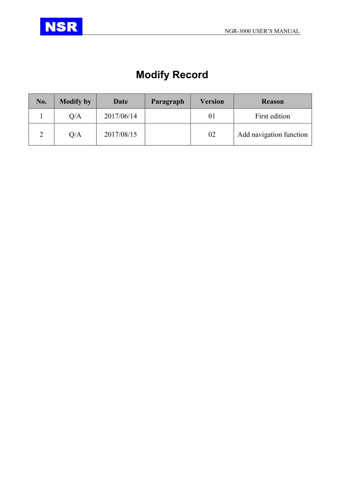
Modify Record
No. Modify by Date Paragraph Version Reason
1 Q/A 2017/06/14 01 First edition
2 Q/A 2017/08/15 02 Add navigation function

NGR-3000 USER’S MANUAL
SAFETY INSTRUCTIONS FOR THE OPERATOR
Warning Keep away from heat source or direct sunshine.
Prohibition Don’t open the equipment. Only qualified personnel should work inside the equipment. Don’t disassemble or try to modify the equipment.
Dangerous Turn off the power immediately when smoke or fire is emitted.
SAFETY INSTRUCTIONS FOR THE INSTALLER
Warning Connect the earthing cord to ship’s body. Observe the compass safe distance to prevent deviation of an onboard magnetic compass.
Prohibited Don’t open the equipment unless you have fully understood the structure and circuits of the equipment. Only qualified personnel should work inside the equipment. Don’t disassemble or try to modify the equipment.
Dangerous Turn off the power at power distribution board before installation.

NGR-3000 USER’S MANUAL
NGR-3000 OM E. 20170815-02
TABLE OF CONTENTS
1. PRODUCT FEATURES ...................................................................................................... 1
2. OPERATIONAL OVERVIEW .............................................................................................. 2
2.1 CONTROL DESCRIPTION .............................................................................................................. 2
2.2 TURN ON AND OFF THE POWER .................................................................................................. 4
2.3 ADJUST DIMMER AND CONTRAST .............................................................................................. 4
2.4 DISPLAY MODES............................................................................................................................... 5
2.4.1 Plotter display................................................................................................................ 5
2.4.2 Highway display ............................................................................................................ 6
2.4.3 Nav data display ........................................................................................................... 7
2.4.4 Compass display .......................................................................................................... 8
2.5 BASIC MENU OPERATION................................................................................................................... 8
2.6 HOW TO ENTER CHARACTER DATA........................................................................................................ 9
3. PLOTTER DISPLAY OVERVIEW .................................................................................... 10
3.1 ENLARG/SHRINK THE DISPLAY RANGE ............................................................................................... 10
3.2 STOP THE NAVIGATION BY THE CURRENT ROUTE ....................................................................................... 10
3.3 ADD A NEW WAYPOINT TO THE ROUTE .................................................................................................. 11
4. WAYPOINT AND ROUTE ................................................................................................. 11
4.1 REGISTERING WAYPOINTS ................................................................................................................ 12
4.1.1 Insert a NEW waypoint .............................................................................................. 13
4.1.2 EDIT a waypoint ......................................................................................................... 13
4.1.3 DELETE a waypoint ................................................................................................... 14
4.2 ROUTE PLANNING .......................................................................................................................... 14
4.2.1 Edit a route .................................................................................................................. 15
4.2.2 Navigation by the Route Forward ........................................................................... 16
4.2.3 Navigation by the Route Reverse ........................................................................... 17
4.2.4 Stop navigation ........................................................................................................... 18
4.2.5 Create a new route .................................................................................................... 18
4.2.6 Delete a route ............................................................................................................. 18
5. NAVIGATION SETTING .................................................................................................. 19
5.1 SETUP XTE (CROSS TRACK ERROR) ALARM ........................................................................................ 19
5.2 SET UP SPEED ALARM ..................................................................................................................... 20
5.3 SET UP ARRIVAL ALARM AND ANCHOR WATCH ALARM ...................................................................... 21
5.4 SET UP THE TRACK RECORD .............................................................................................................. 22
6. MAINTENANCE & DIAGNOSTICS .................................................................................. 24

NGR-3000 USER’S MANUAL
NGR-3000 OM E. 20170815-02
6.1 MAINTENANCE .............................................................................................................................. 24
6.2 ERROR ALARMS DISPLAYED .............................................................................................................. 24
6.3 DIAGNOSTIC TEST .......................................................................................................................... 24
6.3.1 Software version ...................................................................................................... 25
6.3.2 GNSS monitoring ..................................................................................................... 26
6.3.3 Key test ...................................................................................................................... 26
6.3.4 LCD test .................................................................................................................... 26
6.3.5 Erase navigation data.............................................................................................. 26
6.3.6 Factory default .......................................................................................................... 26
7. MENU OPERATION .......................................................................................................... 28
7.1 BASIC MENU OPERATION ......................................................................................................... 28
7.2 GNSS SETTING ........................................................................................................................... 28
7.2.1 GEODETIC DATUM .................................................................................................. 28
7.2.2 RAIM ............................................................................................................................ 29
7.2.3 ACCURACY LEVEL .................................................................................................. 29
7.2.4 RTCM ........................................................................................................................... 30
7.3 SYSTEM SETTING ....................................................................................................................... 30
7.3.1 KEY BUZZER ............................................................................................................. 30
7.3.2 LCD/KEY DIMMER .................................................................................................... 30
7.4 ALARM SETTING ........................................................................................................................ 30
7.4.1 ALARM LIST ............................................................................................................... 30
7.4.2 ALARM PERIOD ........................................................................................................ 30
7.4.3 ALARM HISTORY ...................................................................................................... 30
8. INSTALLATION ................................................................................................................. 31
8.1 INSTALLATION OF MAIN UNIT ................................................................................................... 31
8.2 INSTALLATION OF ANTENNA UNIT ............................................................................................ 31
8.3 CABLING ................................................................................................................................... 32
8.3.1 POWER CONNECTION .......................................................................................... 32
8.3.2 GPS DATA OUTPUT................................................................................................ 32
8.3.3 GROUNDING ............................................................................................................ 32
8.4 INITIAL SETTINGS ...................................................................................................................... 32
8.4.1 SENTENCE SETTING ............................................................................................. 32
8.1.2 BAUD RATE SETTING ........................................................................................... 35
APPEDIX I MENU TREE ..................................................................................................... 36
APPEDIX II TECHNICAL SPECIFICATIONS .................................................................... 37
APPEDIX III SENTENCE DISCRIPTION ........................................................................... 38
APPEDIX IV INSTALLATION DRAWINGS ....................................................................... 54

NGR-3000 USER’S MANUAL
NGR-3000 OM E. 20170815-02 1
1. PRODUCT FEATURES
The NGR-3000 is a GPS NAVIGATOR and consists of a display unit and an antenna unit.
The high sensitive GPS NAVIGATOR tracks up to 50 satellites simultaneously. It ensures optimum
accuracy in determination of vessel position, course and speed.
The main features of the NGR-3000 are:
• Comprehensive navigation data displays.
• Alarms: Lost of Position.
• Lost of differential signal, HDOP Exceeded.
• Menu-driven operation.
• 7 inch, color LCD, touch screen operation
• 2 GPS data outputs, 1 INS output, 1 INS input.
• A DGPS beacon receiver (external) may be connected to the NGR-3000 to add DGPS function.
The product meets the requirements of relative IMO and IEC regulation & standards, including
IMO MSC112 (73), IEC61108-1, etc.
EQUIPMENT LIST:
Scope of Supply
No. Name Quantity Description
1 NGR-3000 Main Unit 1
2 GPS Antenna 1 Cable length 10m or 20m
3 Installation Materials
3.1 Mount Pole 1
3.2 Steel Tie 2
3.3 Accessories 1
4 Options
4.1 DGPS Beacon
4.2 Flush Mount Brackets

NGR-3000 USER’S MANUAL
NGR-3000 OM E. 20170815-02 2
2. OPERATIONAL OVERVIEW
2.1 CONTROL DESCRIPTION
The GPS NAVIGATOR can by operated by key & knob on panel or touch-screen.
When operating with knob, turn the knob to select an item on screen and press the knob to confirm
the selection.
Panel Button Description
Turn to select an item.
Press down to confirm the selection or input.
PWR Power ON/OFF.
To power OFF, press and hold this key more than 3
seconds.
DIM Brightness key for LCD brightness control.
Touch-screen Button Description
MENU Enter the Menu, and use as delete button in input
option.
DATA
Change among four screens:
- Plotter display;
- Highway display;
- Compass display;
- Nav data display.
ACK ALL Acknowledge Alarm.
NGR-3000 USER’S MANUAL
NGR-3000 OM E. 20170815-02 3
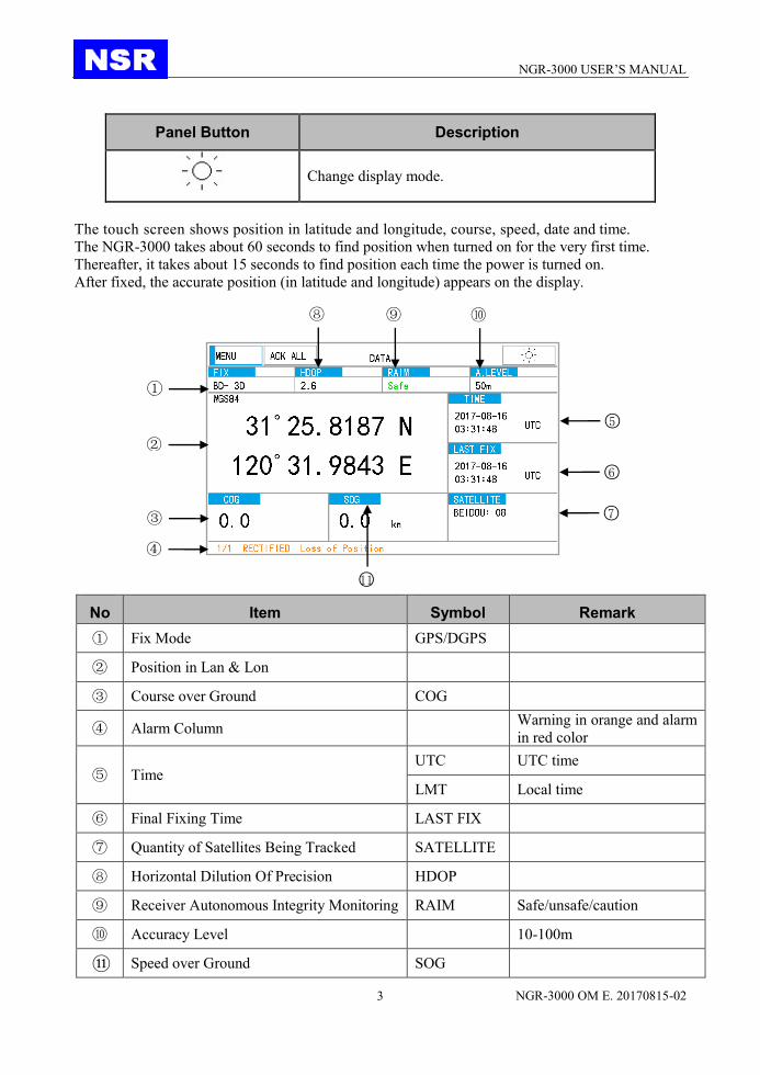
Panel Button Description
Change display mode.
The touch screen shows position in latitude and longitude, course, speed, date and time.
The NGR-3000 takes about 60 seconds to find position when turned on for the very first time.
Thereafter, it takes about 15 seconds to find position each time the power is turned on.
After fixed, the accurate position (in latitude and longitude) appears on the display.
No Item Symbol Remark
① Fix Mode GPS/DGPS
② Position in Lan & Lon
③ Course over Ground COG
④ Alarm Column Warning in orange and alarm
in red color
⑤ Time UTC UTC time
LMT Local time
⑥ Final Fixing Time LAST FIX
⑦ Quantity of Satellites Being Tracked SATELLITE
⑧ Horizontal Dilution Of Precision HDOP
⑨ Receiver Autonomous Integrity Monitoring RAIM Safe/unsafe/caution
⑩ Accuracy Level 10-100m
⑪ Speed over Ground SOG
⑨
①
②
③ ④
⑩
○11
○6
○7
○5
⑧

NGR-3000 USER’S MANUAL
NGR-3000 OM E. 20170815-02 4
Indication Meaning
GP-2D/ GP-3D GPS fix
GP-D2D/GP-D3D DGPS fix
BD-2D/BD-3D BD fix
BD-D2D/BD-D3D DBD fix
GN-2D/GN-3D GN fix
GN-D2D/GN-D3D DGN fix
2.2 TURN ON AND OFF THE POWER Turn on the power
Press the PWR button to turn on the power.
Usually it will take about one minute to find its position when turned on for the very first time.
The equipment shows receiver status at the bottom of the screen.
Turn off the power
Press and hold down the PWR button for 3s until the screen goes blank.
2.3 ADJUST DIMMER AND CONTRAST There are two ways to adjust the brightness and contrast of the LCD.
- Adjust the brightness in the [SYSTEM SETTING].
- Press the DIM button to adjust the brightness.
Note:
When the power is turned off, the last status of brightness is stored. Therefore when the power
is turned on, the screen will display with the last brightness before powered off.
NGR-3000 USER’S MANUAL
NGR-3000 OM E. 20170815-02 5
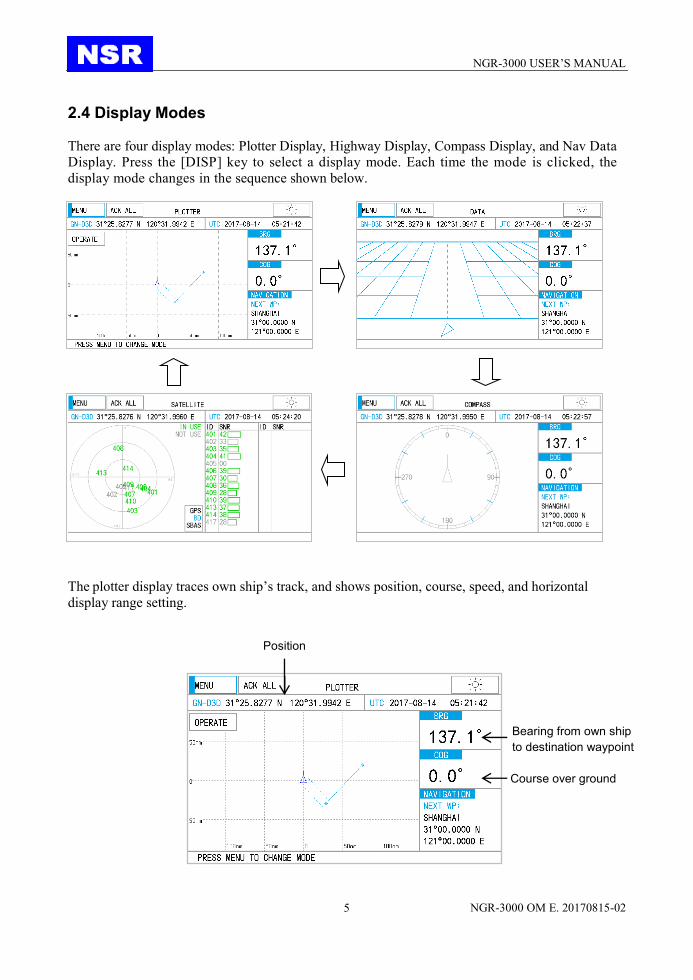
2.4 Display Modes There are four display modes: Plotter Display, Highway Display, Compass Display, and Nav Data
Display. Press the [DISP] key to select a display mode. Each time the mode is clicked, the
display mode changes in the sequence shown below.
2.4.1 Plotter display
The plotter display traces own ship’s track, and shows position, course, speed, and horizontal
display range setting.
Position
Course over ground
Bearing from own ship
to destination waypoint

NGR-3000 USER’S MANUAL
NGR-3000 OM E. 20170815-02 6
2.4.2 Highway display The highway display provides a 3-D view of own ship’s progress toward destination. Nav data is
also shown.
Cursor position
Range
Own ship mark Speed
Cursor mark
Own ship mark
Bearing from own ship
to destination waypoint
Course over ground
NGR-3000 USER’S MANUAL
NGR-3000 OM E. 20170815-02 7
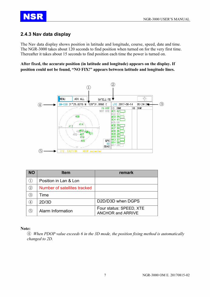
2.4.3 Nav data display The Nav data display shows position in latitude and longitude, course, speed, date and time.
The NGR-3000 takes about 120 seconds to find position when turned on for the very first time.
Thereafter it takes about 15 seconds to find position each time the power is turned on.
After fixed, the accurate position (in latitude and longitude) appears on the display. If
position could not be found, “NO FIX!” appears between latitude and longitude lines.
Note:
④ When PDOP value exceeds 6 in the 3D mode, the position fixing method is automatically
changed to 2D.
NO Item remark
① Position in Lan & Lon
② Number of satellites tracked
③ Time
④ 2D/3D D2D/D3D when DGPS
⑤ Alarm Information Four status: SPEED, XTE
ANCHOR and ARRIVE
①
③ ④
⑤
②

NGR-3000 USER’S MANUAL
NGR-3000 OM E. 20170815-02 8
2.4.4 Compass display The compass display provides course with ship’s speed, and position.
2.5 Basic Menu Operation Most operations of your unit are done through the menu. Below is to introduce how to select a
menu and change menu settings. If you get lost in operation, press the [PWR] key to return to
the MAIN menu. Please refer to complete MENU TREE in the Appendix.
1) Click the [MENU] to display the menu.
2) Turn the knob and press the knob to confirm the selection or click directly to select an item
on screen.
Course over ground
Date and time
2D/3D
Own ship position
Bearing from own ship
to destination waypoint
Alarm information

NGR-3000 USER’S MANUAL
NGR-3000 OM E. 20170815-02 9
2.6 How to enter character data In some instances it is necessary to enter character data. The example below shows how to
enter a waypoint by soft keyboard on screen.
Operate the menus until the above screen is got. (Please refer to WAYPOINT/ROUTE)
1) When the first line is selected, click EDIT to locate the first character to edit.
2) Click RENAME to rename the route desired.
3) Click the character among A-Z desired. Turn the knob to select an item on screen and
press the knob to confirm the selection.
4) Click the [√] to finish.

NGR-3000 USER’S MANUAL
NGR-3000 OM E. 20170815-02 10
3. PLOTTER DISPLAY OVERVIEW
3.1 Enlarg/Shrink the Display Range You may increase or decrease the display range on the plotter display. The horizontal range in
the plotter display is available among 0.02, 0.05, 0.1, 0.2, 0.5, 1, 2, 5, 10, 20, 40, 80, 160 and
320 nautical miles.
1) Click the [OPERATE] key. The pop-up menu appears.
2) Click “ZOOM IN” or “ZOOM OUT” to select range desired.
3) Click on any blank space to finish.
3.2 Stop the navigation by the current route

NGR-3000 USER’S MANUAL
NGR-3000 OM E. 20170815-02 11
Click “STOP” to stop the navigation by the current route.
The route is cleared on the plotter display.
3.3 Add a new waypoint to the route Click “ADD” to add the current position as new waypoint to the route.
The screen will change to WAYPOINT LIST display.
4. WAYPOINT AND ROUTE
Often a trip from one place to another involves several course changes, requiring a series of
waypoints which you navigate to, one after another. The sequence of waypoints leading to the
ultimate destination is called a route. The NGR-3000 can automatically advance to the next
waypoint on a route, so you do not have to change the destination waypoint repeatedly. The
NGR-3000 can store 30 routes and each route may include up to 30 waypoints.
There are two ways to enter Waypoint and Route.
(1) Click NAVIGATION in SETTINGS to open the menu.

NGR-3000 USER’S MANUAL
NGR-3000 OM E. 20170815-02 12
(2) Click PLOTTER in MENU, then click WAYPOINT/ROUTE in OPERATE to open the
menu.
4.1 Registering waypoints
Click NAVIGATION in SETTINGS to open the list.

NGR-3000 USER’S MANUAL
NGR-3000 OM E. 20170815-02 13
1) Turn the knob to select the waypoint desired.
2) Select “ADD”,”DELETE” or “EDIT” desired.
4.1.1 Insert a NEW waypoint Create a new waypoint with the position as own ship’s current position. The new waypoint
will be inserted after the waypoint which is selected by the current cursor.
4.1.2 EDIT a waypoint Edit the selected waypoint.

NGR-3000 USER’S MANUAL
NGR-3000 OM E. 20170815-02 14
1) Click “EDIT” to edit the contents of the waypoint.
2) Click “LAT” or “LON” to locate the first character to edit, turn the knob to select the
character to be edited.
3) Turn the knob to change the characters among 0-9 until the desired character is got. Turn
the knob to move the cursor to the next digit to edit.
4) Turn the knob to select “latitude”, “longitude”.
5) Click the [√] key to finish the waypoint.
4.1.3 DELETE a waypoint Delete the selected waypoint.
4.2 Route Planning
NGR-3000 USER’S MANUAL
NGR-3000 OM E. 20170815-02 15
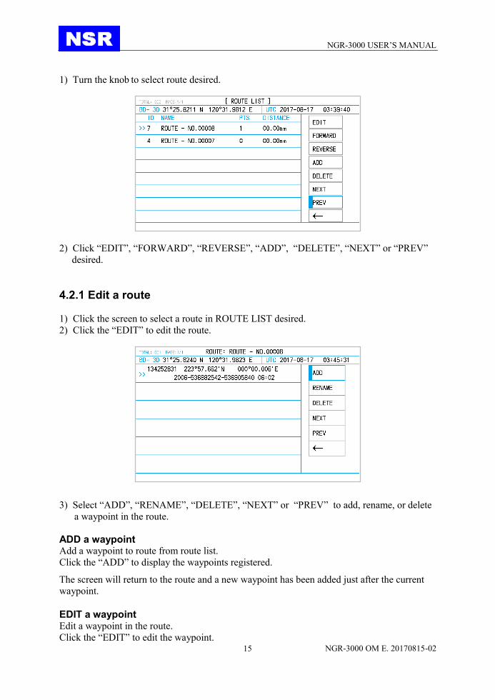
1) Turn the knob to select route desired.
2) Click “EDIT”, “FORWARD”, “REVERSE”, “ADD”, “DELETE”, “NEXT” or “PREV”
desired.
4.2.1 Edit a route
1) Click the screen to select a route in ROUTE LIST desired.
2) Click the “EDIT” to edit the route.
3) Select “ADD”, “RENAME”, “DELETE”, “NEXT” or “PREV” to add, rename, or delete
a waypoint in the route.
ADD a waypoint Add a waypoint to route from route list.
Click the “ADD” to display the waypoints registered. The screen will return to the route and a new waypoint has been added just after the current
waypoint.
EDIT a waypoint Edit a waypoint in the route.
Click the “EDIT” to edit the waypoint.

NGR-3000 USER’S MANUAL
NGR-3000 OM E. 20170815-02 16
It’s in the same way with editing waypoint in waypoint list.
Please refer to “4.1.2 Edit a waypoint”.
RENAME the route Click the “RENAME” , the pop-up menu appears.
The route name can be made of up to 6 characters.
1) Click RENAME to rename the route desired.
2) Click the character among A-Z desired. Turn the knob to select an item on screen and
press the knob to confirm the selection.
3) Click the [√] to finish.
DELETE a waypoint Click the “DELETE” to delete the selected waypoint from the route.
4.2.2 Navigation by the Route Forward
Click the “FORWARD” in MENU to start navigation forward. The plotter screen is
displayed.

NGR-3000 USER’S MANUAL
NGR-3000 OM E. 20170815-02 17
4.2.3 Navigation by the Route Reverse
Click the “REVERSE” to start navigation reversely. The plotter screen is displayed.

NGR-3000 USER’S MANUAL
NGR-3000 OM E. 20170815-02 18
4.2.4 Stop navigation Click the “STOP” to stop navigation and no navigation data is listed on Plotter display.
4.2.5 Create a new route Click the “ADD” to add a new route just after the current route.
4.2.6 Delete a route Click the “DELETE” to delete the selected route from route list.

NGR-3000 USER’S MANUAL
NGR-3000 OM E. 20170815-02 19
5. NAVIGATION SETTING
Select NAVIGATION SETTING in WAYPOINT/ROUTE to open the menu.
5.1 Setup XTE (Cross Track Error) Alarm The XTE alarm warns by an internal buzzer you when own ship is off its intended route.

NGR-3000 USER’S MANUAL
NGR-3000 OM E. 20170815-02 20
1) Click the XTE field ON/OFF.
2) Click the submenu to select ON or OFF as appropriate.
3) Click the XTE value to edit.
4) Click the digits among 0-9 desired until the desired digit is got.
5) Turn the knob to move the cursor to the next digit to edit.
5.2 Set up Speed Alarm The speed alarm is activated when ship’s speed is higher (or lower) than the set values.
1) Select SPEED ALARM.
2) Click the SPEED ALARM to select OFF, HIGH or LOW as appropriate.
OFF: Disables the speed alarm.
LOW: Alarm is activated when speed is lower than the speed set.
HIGH: Alarm is activated when speed is higher than the speed set.
3) Click the SPEED value to edit.
4) Click the digits among 0-9 until the desired digit is got.
5) Turn the knob to move the cursor to the next digit to edit.

NGR-3000 USER’S MANUAL
NGR-3000 OM E. 20170815-02 21
5.3 Set up Arrival Alarm and Anchor Watch Alarm
You may activate the arrival alarm or the anchor watch alarm while they cannot be
activated together.
Arrival alarm
The arrival alarm informs you that own ship is approaching a destination waypoint. The area
that defines an arrival zone is that of a circle which you approach from the out- side of the
circle. The alarm will be activated if own ship enters the circle.
1) Select ARV(arrival) from ARV/ANC/OFF.
2) Click the ALARM value to edit.
3) Click the digits among 0-9 until the desired digit is got.
4) Turn the knob to move the cursor to the next digit to edit.
The alarm range is (0.01-99.99 nm).
Anchor watch alarm The anchor watch alarm sounds to warn you that own ship is moving beyond the set area.

NGR-3000 USER’S MANUAL
NGR-3000 OM E. 20170815-02 22
Before setting the anchor watch alarm, set current position as destination.
1) Select ANC (anchor) from ARV/ANC/OFF.
2) Click the ALARM value to edit.
3) Click the digits among 0-9 until the desired digit is got.
4) Turn the knob to move the cursor to the next digit to edit..
The alarm range is (0.01-99.99 nm).
NOTE: Anchor watch alarm and arrival alarm are combined to serve a route. After a route is
finished while the destination is arrived at, keep the navigation on the route while
setting ANC. The anchor watch starts.
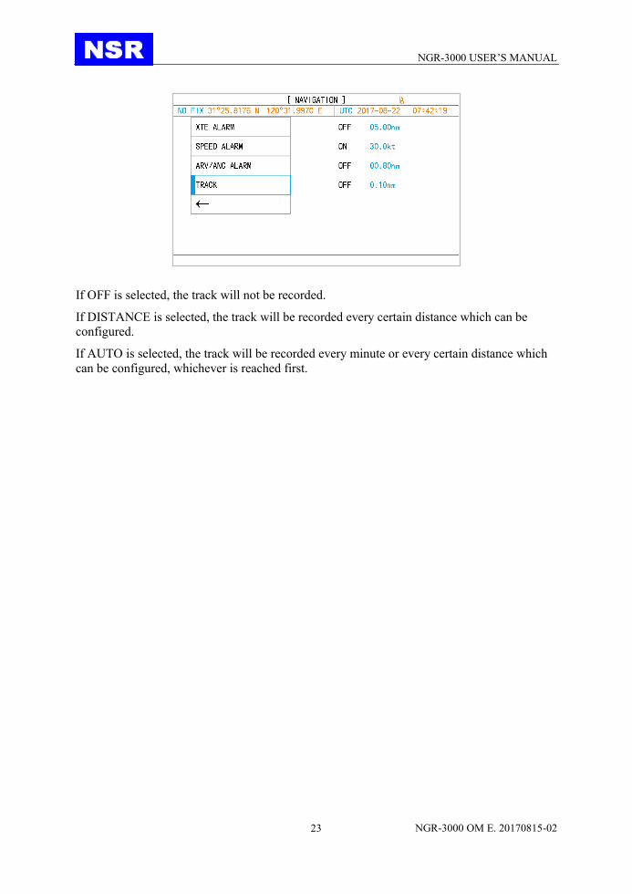
5.4 Set up the Track record TRACK is to set the interval of every two recorded dots.
NGR-3000 USER’S MANUAL
NGR-3000 OM E. 20170815-02 23
If OFF is selected, the track will not be recorded. If DISTANCE is selected, the track will be recorded every certain distance which can be
configured. If AUTO is selected, the track will be recorded every minute or every certain distance which
can be configured, whichever is reached first.

NGR-3000 USER’S MANUAL
NGR-3000 OM E. 20170815-02 24
6. MAINTENANCE & DIAGNOSTICS
6.1 Maintenance Check the following points regularly to maintain performance:
• Check that connectors on the rear panel are firmly tightened and free of rust.
• Check that the ground system is free of rust and the ground wire is tightly fastened.
• Check the antenna for damage. Replace if damaged.
• Dust and dirt on the keyboard and display screen may be removed with a soft cloth. Do not
use chemical cleaners to clean the equipment; they may remove paint and markings.
6.2 Error alarms displayed When an error occurs, the alarm will be displaying on the current screen. The meanings
of the alarms are stated in below table:
The alarm parameters are set in NAVIGATION SETTING.
6.3 Diagnostic Test The diagnostic test checks software version, keyboard and LCD for proper operation.
Message Meaning, Remedy
ANCHOR! Anchor watch alarm setting violated.
ARRIVAL! Arrival alarm setting violated.
NO FIX! No GPS signal. Check antenna cable.
SPEED! Speed alarm setting violated.
XTE! XTE alarm setting violated.
OUTPUT ERROR! Too many sentences selected.

NGR-3000 USER’S MANUAL
NGR-3000 OM E. 20170815-02 25
6.3.1 Software version Select SOFTWARE VERSION item and press the [ENT] key to check the software version.
NGR-3000 USER’S MANUAL
NGR-3000 OM E. 20170815-02 26
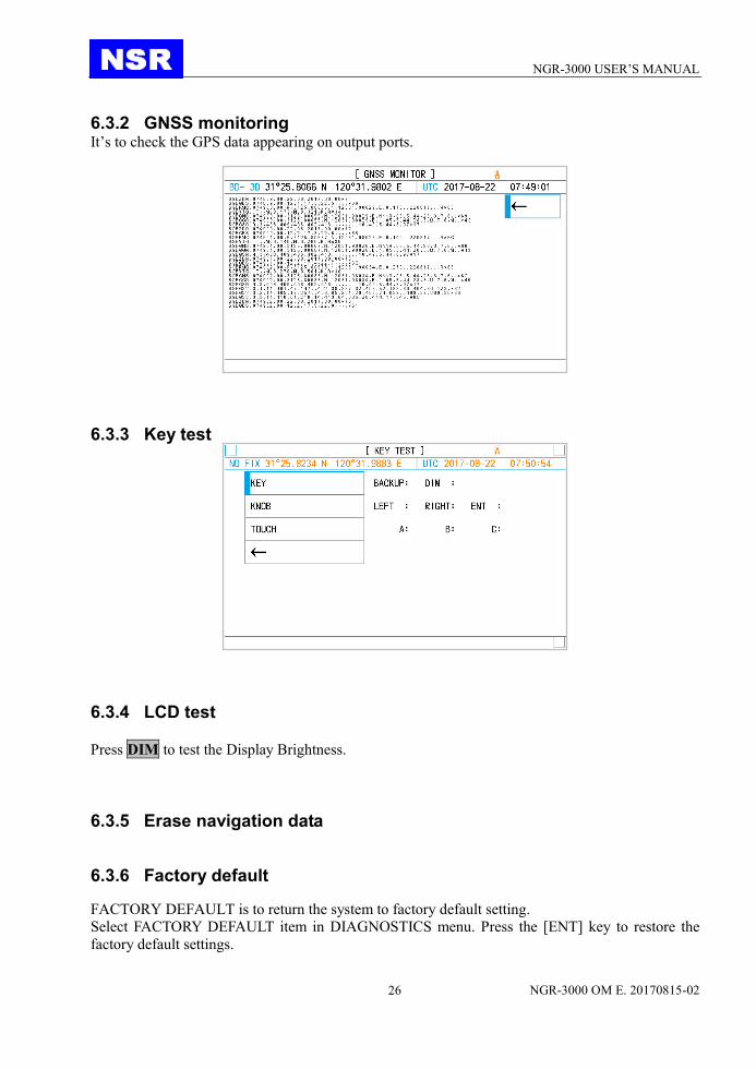
6.3.2 GNSS monitoring It’s to check the GPS data appearing on output ports.
6.3.3 Key test
6.3.4 LCD test
Press DIM to test the Display Brightness.
6.3.5 Erase navigation data
6.3.6 Factory default
FACTORY DEFAULT is to return the system to factory default setting.
Select FACTORY DEFAULT item in DIAGNOSTICS menu. Press the [ENT] key to restore the
factory default settings.

NGR-3000 USER’S MANUAL
NGR-3000 OM E. 20170815-02 27
NOTE: The navigation settings and GPS settings will restore to factory default while the waypoints and
routes registered remain unchanged.
NGR-3000 USER’S MANUAL
NGR-3000 OM E. 20170815-02 28
7. MENU OPERATION
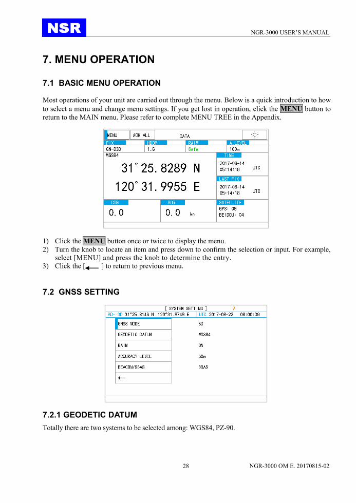
7.1 BASIC MENU OPERATION Most operations of your unit are carried out through the menu. Below is a quick introduction to how
to select a menu and change menu settings. If you get lost in operation, click the MENU button to
return to the MAIN menu. Please refer to complete MENU TREE in the Appendix.
1) Click the MENU button once or twice to display the menu.
2) Turn the knob to locate an item and press down to confirm the selection or input. For example,
select [MENU] and press the knob to determine the entry.
3) Click the [ ] to return to previous menu.
7.2 GNSS SETTING
7.2.1 GEODETIC DATUM
Totally there are two systems to be selected among: WGS84, PZ-90.

NGR-3000 USER’S MANUAL
NGR-3000 OM E. 20170815-02 29
7.2.2 RAIM
RAIM (Receiver Autonomous Integrity Monitoring) can be set ON or OFF.
When set ON, RAIM will display SAFE, UNSAFE or CAUTION in below conditions:
Conditions for the "safe" state
The result of integrity calculation by means of RAIM will be stated as "safe", if the integrity
calculation can be performed with a confidence level above 95 % for the selected accuracy level
and RAIM calculates the probable position error to be within the selected accuracy level.
This generally requires at least 5 "healthy" satellites available and in a robust geometry, i.e. the
worst 4 satellite geometry is still suitable for navigation.
Conditions for the "caution" state
The "caution" status will be used to indicate:
– insufficient information to reliably calculate with a confidence level above 95 % for the selected
accuracy level, or
– the probability of false alarms >5 %, or
– the probability of not detecting an error condition >5 %.
Those conditions may occur if an insufficient number of satellites are available, for example 4 or 5
with 2 satellites "close" together in azimuth and elevation, causing the geometry to degrade to the
point that the RAIM calculation becomes unreliable. Note that the resulting accuracy based on 4 or
5 satellites in use may be within the selected accuracy level, but the RAIM algorithm cannot verify
it.
Conditions for the "unsafe" state
The "unsafe" status will be used if the integrity calculation is performed with a confidence level
above 95 % for the selected accuracy level, and RAIM calculates the probable position error
exceeding the selected accuracy level. Note that also here a robust geometry is required to reach
this confidence level. The "unsafe" state can be reached when satellite range errors degrade the
navigation solution, causing the resulting accuracy to be outside the selected accuracy level.
7.2.3 ACCURACY LEVEL
Accuracy level can be set between 10-100m.

NGR-3000 USER’S MANUAL
NGR-3000 OM E. 20170815-02 30
7.2.4 RTCM
RTCM can be set ON or OFF. When set ON, DGPS beacon input will be checked by NGR-3000.
7.3 SYSTEM SETTING
7.3.1 KEY BUZZER
Buzzer can be muted so that operation is not heard.
7.3.2 LCD/KEY DIMMER
Dimmer can be adjusted either by DIM button or set in menu.
7.4 ALARM SETTING
When an error occurs, the alarm will be displaying on the current screen. The meanings of
the alarms are stated in below table:
When one of below three conditions met, an audible alarm will be generated:
1. GPS not fixed.
2. HDOP greater than 4.
3. DGPS input not detected when RTCM is set ON.
7.4.1 ALARM LIST
It’s to check current alarm events.
7.4.2 ALARM PERIOD
Alarm period can be set between 1-5 minutes.
When an alert occurs, a warning will be displayed at the bottom of screen and can be heard as a
warning tone.
If an alert lasts for above set period, an alarm will be displayed at the bottom of screen and can be
heard as an alarm tone.
Either a warning tone or an alarm tone can be muted by pressing the alert on screen or being set in
menu.
7.4.3 ALARM HISTORY
All history alarms will be displayed here.

NGR-3000 USER’S MANUAL
NGR-3000 OM E. 20170815-02 31
8. INSTALLATION
8.1 INSTALLATION OF MAIN UNIT
The main unit can be installed on a table-top, on the overhead, or in a panel (optional flush
mounting brackets required). Refer to the outline drawings at the end of this manual for
installation instructions. When selecting a mounting location, keep in mind the following points:
• Locate the unit away from exhaust pipes and vents.
• The mounting location should be well ventilated.
• Mount the unit where shock and vibration are minimal.
• Locate the unit away from equipment which generates electromagnetic fields such as a motor or
generator.
• Allow sufficient maintenance space at the sides and rear of the unit and leave sufficient slack in
cables, to facilitate maintenance and servicing.
• Observe the following compass safe distances to prevent deviation of a magnetic compass.
Standard compass, 0.5 m, Steering compass, 0.3 m.
8.2 INSTALLATION OF ANTENNA UNIT
Install the antenna unit referring to the antenna installation diagram at the end of this manual. When
selecting a mounting location for the antenna unit, keep in mind the following points:
• Do not shorten the antenna cable.
• Select a location out of the radar beam. The radar beam will obstruct or prevent reception of the
GPS signal.
• The location should be well away from a VHF/UHF antenna. A GPS NAVIGATOR is interfered
by a harmonic wave of a VHF/ UHF antenna.
• There should be no interfering object within the line-of-sight to the satellites. Objects within
line-of-sight to a satellite, for example, a mast, may block reception or prolong acquisition
time.
• Mounting the antenna unit as high as possible keeps it free of interfering objects and water
spray, which can interrupt reception of GPS satellite signal if the water freezes.
• If the antenna cable is to be passed through a hole which is not large enough to pass the
connector, you may unfasten the connector. Refasten it after running the cable through the
hole.

NGR-3000 USER’S MANUAL
NGR-3000 OM E. 20170815-02 32
8.3 CABLING
8.3.1 POWER CONNECTION
PIN NO DESCRIPTION
13 PWR (+ 24V)
14 PWR (0V)
The power cable with a rated capacity of 3A should be used. Pin definition for the connector is
showed above.
Suggest using the 3A DC Power Supply Unit (DC 24V output).
8.3.2 GPS DATA OUTPUT
There are totally 2 RS422 GPS data ports. The output data format is NMEA0183, as IEC61162-1
standard.
PIN NO DESCRIPTION
5 GPS OUT 1+
6 GPS OUT 1-
7 GPS OUT 2+
8 GPS OUT 2-
9 INS OUT+
10 INS OUT+
11 INS IN+
12 INS IN+
The default baud rate is 4800 bps, which can also be reset into among 9600 / 19200 / 38400 bps.
8.3.3 GROUNDING
The display unit contains a CPU. While it is operating, it radiates noise, which can interfere with
radio equipment. Ground the unit as follows to prevent interference:
• The ground wire should be 1.25sq or larger.
• The ground wire should be as short as possible.
8.4 INITIAL SETTINGS
This equipment can output navigation data to external equipment, in NMEA 0183 format. For
example, it can output position data to a radar or echo sounder for display on its display screen.
8.4.1 SENTENCE SETTING

NGR-3000 USER’S MANUAL
NGR-3000 OM E. 20170815-02 33
For each port, up to five sentences can be selected to output. If the selected sentences exceed 5
items, OVERFLOW will be indicated in the relative column. In this case, OUTPUT ERROR will
also be shown in displayed screens.
Move the cursor to the item and click it to select it or deselect a sentence.

NGR-3000 USER’S MANUAL
NGR-3000 OM E. 20170815-02 34
Data sentence description
ACN: Equipment is operating normally, or for supervision of a connection between two units.
ALC: Cyclic alert list. The cyclic alert list transmission shall never stop. When all alerts are in
normal state the cyclic alert list is empty i.e. number of alert entries is 0.
ALF: Report an alert condition and the alert state of a device. An ALF message shall be
published for an alert each time the alert information in this sentence changes and on alert
request (see ALC – Cyclic alert list).
GNS: Fix data for GPS, GLONASS.
GBS: Support Receiver Autonomous Integrity Monitoring (RAIM).
GGA: GPS position fixing condition (time of fix, latitude, longitude, receiving condition,
number of satellites used, DOP).
HBT: The sentence is transmitted at regular intervals specified in the corresponding equipment
standard. The repeat interval may be used by the receiving unit to set the time-out value
for the connection supervision.
RMC: Generic navigational information (UTC time, latitude, longitude, ground speed, true course,
day, month, year).
VTG: Actual track and ground speeds.
ZDA: UTC time (day, month, year).
DTM: Datum reference.
GSA: GNSS receiver operating mode, satellites used in the navigation solution reported by the
GGA 2148 or GNS sentences, and DOP values.
NOTE: As default, GNS, GBS, GGA, RMC, ZDA and DTM are selected.

NGR-3000 USER’S MANUAL
NGR-3000 OM E. 20170815-02 35
8.1.2 BAUD RATE SETTING
Select each of four outputs to configure the baud rate.
Default baud rate of all ports is 4800bps.
Move the cursor to the output and click it continuously until a desired rate is shown.
1、The baud rate can be selected among 4800/ 9600/ 19200/ 38400bps.
2、The NMEA Version can be selected among 1.5/ 2.0/ 2.3/IEC61162 Ed4/IEC61162 Ed5.

NGR-3000 USER’S MANUAL
NGR-3000 OM E. 20170815-02 36
APPEDIX I MENU TREE
NGR-3000 USER’S MANUAL
NGR-3000 OM E. 20170815-02 37
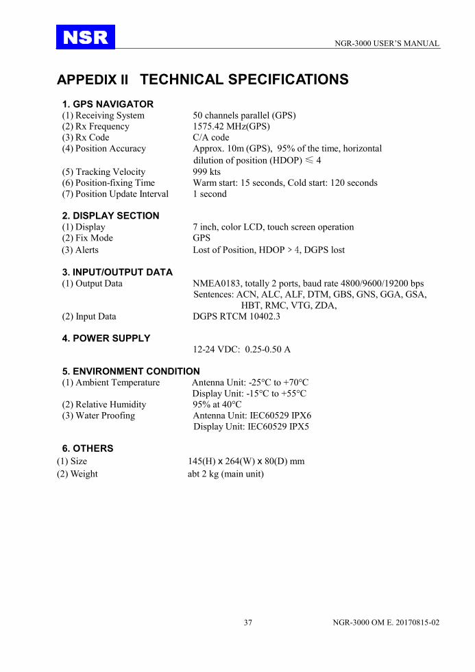
APPEDIX II TECHNICAL SPECIFICATIONS
1. GPS NAVIGATOR (1) Receiving System 50 channels parallel (GPS)
(2) Rx Frequency 1575.42 MHz(GPS)
(3) Rx Code C/A code
(4) Position Accuracy Approx. 10m (GPS), 95% of the time, horizontal
dilution of position (HDOP) ≤ 4
(5) Tracking Velocity 999 kts
(6) Position-fixing Time Warm start: 15 seconds, Cold start: 120 seconds
(7) Position Update Interval 1 second
2. DISPLAY SECTION (1) Display 7 inch, color LCD, touch screen operation
(2) Fix Mode GPS
(3) Alerts Lost of Position, HDOP﹥4, DGPS lost
3. INPUT/OUTPUT DATA (1) Output Data NMEA0183, totally 2 ports, baud rate 4800/9600/19200 bps
Sentences: ACN, ALC, ALF, DTM, GBS, GNS, GGA, GSA,
HBT, RMC, VTG, ZDA,
(2) Input Data DGPS RTCM 10402.3
4. POWER SUPPLY 12-24 VDC: 0.25-0.50 A
5. ENVIRONMENT CONDITION (1) Ambient Temperature Antenna Unit: -25°C to +70°C
Display Unit: -15°C to +55°C
(2) Relative Humidity 95% at 40°C
(3) Water Proofing Antenna Unit: IEC60529 IPX6
Display Unit: IEC60529 IPX5
6. OTHERS
(1) Size 145(H) x 264(W) x 80(D) mm
(2) Weight abt 2 kg (main unit)

NGR-3000 USER’S MANUAL
NGR-3000 OM E. 20170815-02 38
APPEDIX III SENTENCE DISCRIPTION

NGR-3000 USER’S MANUAL
NGR-3000 OM E. 20170815-02 39
ACN – Alert command $--ACN,hhmmss.ss,aaa,x.x,x.x,c,a*hh <CR><LF>
| | | | | | | | | | | +--------------------------------- 6 | | | | +---------------------------- 5 | | | +-------------------------- 4 | | +------------------------- 3 | +----------------------- 2
+---------------------------- 1 1. Time (see Note 1) 2. Manufacturer mnemonic code (see Note 2) 3. Alert Identifier (see Note 3) 4. Alert Instance, 1 to 999999 (see Note 4)
5. Alert command, A, Q, O or S (see Note 5) 6. Sentence status flag (see Note 6)
NOTE 1: Release time of the alert command. (e.g. for VDR purposes), optional can be a null
field. Sender is allowed to use all alternatives defined in Table 5 Field type
summary. Receiver is allowed to ignore content of this field. If receiver does not
ignore this field it should support all alternatives defined in Table 5 Field type
summary.
NOTE 2: Used for proprietary alerts defined by the manufacturer. For standardized alerts this
should be a null field.
NOTE 3: The alert identifier is unique within a single alert source. The alert identifier is a
variable length integer field of maximum 7-digit integer. It identifies the type of the
alert e.g. a “lost target” alert. Standardized alerts use unique alert identifiers
described in equipment standards. Number range 10000-9999999 is reserved for
proprietary alerts. Alert Identifier examples: “001”, “2456789”, “245” .
NOTE 4: The alert instance identifies the current instance of an alert to distinguish alerts of
the same type (Alert identifier) and from the same source (e.g. dangerous target).
Alert instance is maximum 6-digit integer from 1 to 999999. The number of alert
instance can be freely defined by the manufacturer as long as it is unique for one
type of alert (alert identifier). It is not permitted to modify the alert instance within a
life cycle of a distributed alert (from ‘active & unacknowledged’ state until
‘normal’ state is reached). It can be also a null field, when there is only one alert of
that type.
NOTE 5: This should not be null field
acknowledge : A
request / repeat information : Q
responsibility transfer: O
silence : S
NOTE 6: This field should be “C” and should not be null field. This field indicates a
command. A sentence without “C” is not a command.

NGR-3000 USER’S MANUAL
NGR-3000 OM E. 20170815-02 40
ALC - Cyclic alert list $--ALC, xx, xx, xx, x.x, aaa, x.x, x.x, x.x, ........, aaa, x.x, x.x, x.x*hh <CR><LF>
| | | | | | | | | | | | | | | | | | | | | | | | | | | | | | | | | | +---------------+----------- 7 | | | | | | | | +--+-------------------------- 6 | | | | +-----+----+---+------------------------------ 5 | | | +---------------------------------------------- 4 | | +--------------------------------------------- 3 | +------------------------------------------- 2 +------------------------------------------ 1
1. Total number of sentences for this message, 01 to 99 (see Note 1) 2. Sentence number, 01 to 99 (see Note 1) 3. Sequential message identifier, 00 to 99 (see Note 2) 4. Number of alert entries (see Note 3)
5. Alert entry 1 6. Additional Alert entries (see Note 4)
7. Alert entry n (see Note 4)
NOTE 1: The first field specifies the total number of sentences used for a message, minimum
value 1. The second field identifies the order of this sentence in the message,
minimum value 1, These cannot be null fields.
NOTE 2: The sequential message identifier relates all sentences that belong to a group of
multiple sentences (i.e. message). Multiple sentences (see Note 1) with the same
sequential message identifier, make up one message.
NOTE 3: Contains the number of alert entries transported within this sentence.
NOTE 4: Alert entry 0 – n: Each alert entry consists of four fields:
• Manufacturer Identifier (see ALF Manufacturer Identifier)
• Alert Identifier (see ALF Alert Identifier)
• Alert instance (see ALF Alert instance)
• Revision Counter (see ALF Revision Counter)
Each entry identifies a certain alert with a certain state. It is not allowed that an alert entry is
split between two ALC sentences.

NGR-3000 USER’S MANUAL
NGR-3000 OM E. 20170815-02 41
ALF - Alert sentence $--ALF, x, x,x,hhmmss.ss,a,a,a,aaa,x.x,x.x,x.x,x,c---c*hh <CR><LF>
| | | | | | | | | | | | | | | | | | | | | | | | | +------------------------ 13 | | | | | | | | | | | +------------------------ 12 | | | | | | | | | | +------------------------- 11 | | | | | | | | | +------------------------- 10 | | | | | | | | +-------------------------- 9 | | | | | | | +---------------------------- 8 | | | | | | +--------------------------- 7 | | | | | +----------------------- 6 | | | | +-------------------- 5 | | | +---------------------------- 4 | | +-------------------------- 3 | +----------------------- 2 +---------------------1
1. Total number of ALF sentences for this message, 1 to 2 (see Note 1) 2. Sentence number, 1 to 2 (see Note 1) 3. Sequential message identifier, 0 to 9 (see Note 2) 4. Time of last change (see Note 3)
5. Alert category, A, B or C (see Note 4) 6. Alert priority, E, A, W or C (see Note 5)
7. Alert state, A, S, R, O, U or D (see Note 6) 8. Manufacturer mnemonic code (see Note 7) 9. Alert identifier (see Note 8) 10. Alert instance, 1 to 999999 (see Note 9) 11. Revision counter, 1 to 99 (see Note 10) 12. Escalation counter, 0 to 9 (see Note 11) 13. Alert text (see Note 12)
NOTE 1: The first field specifies the total number of sentences used for a message, minimum
value 1. The second field identifies the order of this sentence in the message,
minimum value 1, These cannot be null fields. When the sentence number is 2, the
following Alert category, Alert priority and Alert state can be null fields.
NOTE 2: The sequential message identifier relates all sentences that belong to a group of
multiple sentences (i.e. message). Multiple sentences (see Note 1) with the same
sequential message identifier, make up one message.
NOTE 3: Time should represent the last time the data within the alert message has changed.
For example changing the alert text by in-/decrementing a contained counter or
count down should cause a revision of alert message and a new time. Time is an
optional field. The time-field is additional information about when this happened
and not used for decision making. There is no mandatory requirement for time
synchronization between the equipment. It should by either a null field (if not used)
or UTC (if used). Sender is allowed to use all alternatives defined in Table 5 Field
type summary. Receiver is allowed to ignore content of this field. If the receiver

NGR-3000 USER’S MANUAL
NGR-3000 OM E. 20170815-02 42
does not ignore this field it should support all alternatives defined in Table 5 Field
type summary.
NOTE 4: The alert category is in compliance with the category definition as described in INS
Performance Standard (MSC.252(83)) and Bridge Alert Management Performance
Standard (MSC.302(87)):
A, Category A: Alerts where information at operator unit directly assigned to the
function generating the alert is necessary, as decision support for the
evaluation of the alert-related condition, e.g. graphical information
of danger of collision or graphical information of danger of
grounding.
B, Category B: Alerts where no additional information for decision support is
necessary besides the information which can be presented using
alert source and alert description text.
C, Category C: Alerts that cannot be acknowledged on the bridge but for which
information is required about the status and treatment of the alerts,
e.g., certain alerts from the engine.
NOTE 5: Alert priority: Emergency Alarm: E, for use with Bridge alert management
Alarm: A
Warning: W
Caution: C
NOTE 6: The alert state transition is defined in Annex J
active – unacknowledged: V
active – silenced: S
active – acknowledged or active: A
active – responsibility transferred: O
rectified – unacknowledged: U
normal: N
NOTE 7: Used for proprietary alerts defined by the manufacturer. For standardized alerts this
should be a null field.
NOTE 8: The alert identifier is unique within a single alert source. The alert identifier is a
variable length integer field of maximum 7-digit integer. It identifies the type of the
alert e.g. a “lost target” alert. Standardized alerts use unique alert identifiers
described in equipment standards. Number range 10000-9999999 is reserved for
proprietary alerts. Alert Identifier examples: “001”, “2456789”, “245” .
NOTE 9: The alert instance identifies the current instance of an alert to distinguish alerts of
the same type (Alert identifier) and from the same source (e.g. dangerous target).
Alert instance is maximum 6-digit integer from 1 to 999999. The number of alert
instance can be freely defined by the manufacturer as long as it is unique for one
type of alert (alert identifier). It is not permitted to modify the alert instance within a
life cycle of a distributed alert (from ‘active & unacknowledged’ state until
‘normal’ state is reached). It can be also a null field, when there is only one alert of
that type.

NGR-3000 USER’S MANUAL
NGR-3000 OM E. 20170815-02 43
NOTE 10: The revision counter is the main method to follow up-to-date status. Revision
counter is also unique for each instance of alert. Revision counter starts with 1
and the step for increment is 1. The count resets to 1 after 99 is used. Revision
counter increments on each change of content of any field of the alert.
NOTE 11: The escalation counter is presenting the number of alert escalations after time
expiration during the state active-unacknowledged. The escalation counter starts
with 0 and the step for increment is 1. The count resets to 1 after 9 is used. The
alert escalation can be the escalation from warning into warning (activation of
audible signal only), the escalation from warning to alarm or the escalation from
alarm to alarm with activation of back-up navigator alarm
NOTE 12: This field is used for Alert title which is mandatory and for additional alert
description which is optional.

NGR-3000 USER’S MANUAL
NGR-3000 OM E. 20170815-02 44
DTM - Datum reference $--DTM,ccc,a,x.x,a,x.x,a,x.x,ccc*hh<CR><LF>
| | | | | | | | | | | | | | | | | +--- 7 | | | | | | | +------ 6 | | | | | | +---------- 5 | | | | +--+------------- 4 | | +---+------------------- 3 | +------------------------- 2 +---------------------------- 1
1. Local datum W84 - WGS84 W72 - WGS72 S85 - SGS85 P90 - PE90 999 - User defined IHO datum code
2. Local datum subdivision code 3. Lat offset, min, N/S 4. Lon offset, min, E/W 5. Altitude offset, m 6. Reference datum W84 - WGS84
W72 - WGS72 S85 - SGS85 P90 - PE90
7. Checksum

NGR-3000 USER’S MANUAL
NGR-3000 OM E. 20170815-02 45
GBS– GNSS satellite fault detection $--GBS, hhmmss.ss, x.x, x.x, x.x, xx, x.x, x.x, x.x, h, h *hh <CR><LF>
| | | | | | | | | | | | | | | +--------------------------- 8 | | | | | | +------------------------- 7 | | | | | +--------------------------- 6 | | | | +------------------------- 5 | | | +------------------------ 4 | | +----------------------- 3 | +--------------------- 2
+---------------------------- 1 1. UTC time of the GGA or GNS fix associated with this sentence 2. Expected error in latitude (see Note 1) 3. Expected error in longitude 4. Expected error in altitude 5. ID number (see Note 2) of most likely failed satellite
6. Probability of missed detection for most likely failed satellite 7.Estimate of bias on most likely failed satellite 8.Standard deviation of bias estimate

NGR-3000 USER’S MANUAL
NGR-3000 OM E. 20170815-02 46
GNS - GNSS fix data $-- GNS, hhmmss.ss, llll.ll, a, yyyyy.yy, a, c--c,xx,x.x,x.x,x.x,x.x,x.x,a *hh<CR><LF>
| | | | | | | | | | | | | | | +--------- 6 | | | | | | +---------- 5 | | | | | +------------- 4 | | | +----------+------------- 3 | +-- +-------------------- 2 +---------------------------- 1
1. UTC of position 2. Latitude, N/S 3. Longitude, E/W 4. Mode indicator 5. Total number of satellites in use, 00-99 6. HDOP

NGR-3000 USER’S MANUAL
NGR-3000 OM E. 20170815-02 47
GGA -Global positioning system fix data $--GGA,hhmmss.ss,llll.lll,a,yyyyy.yyy,a,x,xx,x.x,x.x,M,x.x,M,x.x,xxxx*hh<CR><LF>
| | | | | | | | | | | | | | | | | | | | | | | | | | | | | +----------------
11 | | | | | | | | | | | | | +------------------ 10 | | | | | | | | | | | | +--------------------- 9 | | | | | | | | | | +---+--------------------- 8 | | | | | | | | +---+------------------------- 7 | | | | | | | +------------------------------ 6 | | | | | | +---------------------------- 5 | | | | | +------------------------- 4 | | | +----+------------------------ 3 | +---+---------------------------------- 2 +-------------------------------------------- 1
1. UTC of position 2. Latitude, N/S 3. Longitude, E/W 4. GPS quality indicator (0: No fix, 1: GPS, 2: Differential, 8: Demo mode) 5. Number of satellite in use,00-12, may be different from the number in view 6. Horizontal dilution of precision 7. Antenna altitude above/below mean sea level, m 8. Geoidal separation, m 9. Age of differential GPS data 10. Differential reference station ID, 0000-1023 11. Checksum
NGR-3000 USER’S MANUAL
NGR-3000 OM E. 20170815-02 48
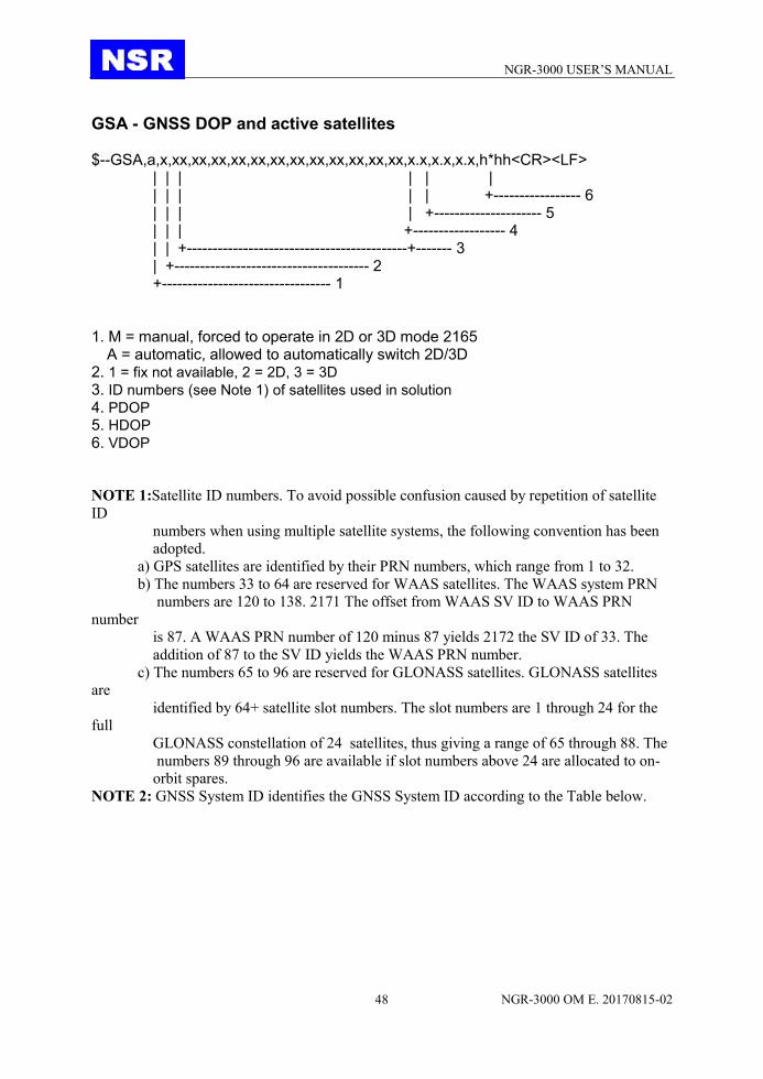
GSA - GNSS DOP and active satellites
$--GSA,a,x,xx,xx,xx,xx,xx,xx,xx,xx,xx,xx,xx,xx,x.x,x.x,x.x,h*hh<CR><LF> | | | | | | | | | | | +----------------- 6 | | | | +--------------------- 5 | | | +------------------ 4 | | +-------------------------------------------+------- 3 | +-------------------------------------- 2 +--------------------------------- 1
1. M = manual, forced to operate in 2D or 3D mode 2165
A = automatic, allowed to automatically switch 2D/3D 2. 1 = fix not available, 2 = 2D, 3 = 3D 3. ID numbers (see Note 1) of satellites used in solution 4. PDOP 5. HDOP 6. VDOP
NOTE 1:Satellite ID numbers. To avoid possible confusion caused by repetition of satellite
ID
numbers when using multiple satellite systems, the following convention has been
adopted.
a) GPS satellites are identified by their PRN numbers, which range from 1 to 32.
b) The numbers 33 to 64 are reserved for WAAS satellites. The WAAS system PRN
numbers are 120 to 138. 2171 The offset from WAAS SV ID to WAAS PRN
number
is 87. A WAAS PRN number of 120 minus 87 yields 2172 the SV ID of 33. The
addition of 87 to the SV ID yields the WAAS PRN number.
c) The numbers 65 to 96 are reserved for GLONASS satellites. GLONASS satellites
are
identified by 64+ satellite slot numbers. The slot numbers are 1 through 24 for the
full
GLONASS constellation of 24 satellites, thus giving a range of 65 through 88. The
numbers 89 through 96 are available if slot numbers above 24 are allocated to on-
orbit spares.
NOTE 2: GNSS System ID identifies the GNSS System ID according to the Table below.

NGR-3000 USER’S MANUAL
NGR-3000 OM E. 20170815-02 49
HBT – Heartbeat supervision sentence
$--HBT, x.x, A, x*hh<cr><lf>
| | | | | +----------------------- 3 | +------------------- 2 +------------------- 1
1. Configured repeat interval (see Note 1) 2. Equipment status (see Note 2) 3. Sequential sentence identifier (see Note 3)
NOTE 1: Configured autonomous repeat interval in seconds. This field should be set to
NULL in response to a query if this feature is supported.
NOTE 2: Equipment in normal operation A = yes, V = no
This field can be used can be used to indicate the current equipment status. This could be the
result of an built-in integrity testing function.
NOTE 3: The sequential sentence identifier provides a message identification number from 0
to 9 that is sequentially assigned and is incremented for each new sentence. The
count resets to 0 after 9 is used.

NGR-3000 USER’S MANUAL
NGR-3000 OM E. 20170815-02 50
RMC- Recommended minimum specific GPS/TRANSIT data $--RMC,hhmmss.ss,A,llll.ll,a,yyyyy.yyy,a,x.x,x.x,xxxxxx,x.x,a,a,a*hh<CR><LF>
| | | | | | | | | | | | | | | | | | | | | | | +-------------------- 9 | | | | | | | | | +--+------------------ 8 | | | | | | | | +-------------------------- 7 | | | | | | | +---------------------------- 6 | | | | | | +---------------------------- 5 | | | | +------+--------------------------- 4 | | +-- -+-------------------------------------- 3 | +---------------------------------------- 2 +-------------------------------------------- 1
1. UTC of position fix 2. Status(see Note 3 ): A=data valid, V=navigation receiver warning 3. Latitude, N/S 4. Longitude, E/W 5. Speed over ground, knots 6. Course over ground, degrees true 7. Date: dd/mm/yy 8. magnetic variation, degrees E/W(see Note 1) 9. Mode indicator (see Notes 2 and 3 ) NOTE 1: E = Easterly variation subtracts from True course
W = Westerly variation adds to True course
NOTE 2: Positioning system mode Indicator A = Autonomous. Satellite system used in non-differential mode in position fix;
D = Differential. Satellite system used in differential mode in position fix;
E = Estimated (dead reckoning) mode;
F = Float RTK. Satellite system used in real time kinematic mode with floating
integers;
M = Manual input mode;
N =No fix. Satellite system not used in position fix, or fix not valid;
P = Precise. Satellite system used in precision mode. Precision mode is
defined as: no deliberate degradation (such as selective availability) and higher
resolution code (P-code) is used to compute position fix. P is also used for
satellite system used in multi-frequency, SBAS or Precise Point Positioning
(PPP)
mode;
R = Real time kinematic. Satellite system used in RTK mode with fixed integers;
S = Simulator mode.
NOTE 3 :The positioning system mode indicator field supplements the positioning system
status field. The status field should be set to V = Invalid for all values of the mode
indicator except for A= Autonomous, D = Differential, F = Float RTK, P = Precise
and R = Real time kinematic. The positioning system mode indicator and status
fields should not be null fields.

NGR-3000 USER’S MANUAL
NGR-3000 OM E. 20170815-02 51
NOTE 4 :The navigational status indicator is according to IEC 61108 requirements on
‘Navigational (or Failure) warnings and status indications’. This field should not be
a NULL field and the character should take one of the following values:
S = Safe. when the estimated positioning accuracy (95 % confidence) is within the
selected accuracy level corresponding to the actual navigation mode, and/or
integrity is available and within the requirements for the actual navigation
mode, and/or a new valid position has been calculated within 1 s for a
conventional craft and 0,5 s for a high speed craft.
C = Caution when integrity is not available.
U = Unsafe when the estimated positioning accuracy (95 % confidence) is less than
the selected accuracy level corresponding to the actual navigation mode, and/or
integrity is available but exceeds the requirements for the actual navigation
mode, and/or a new valid position has not been calculated within 1 s for a
conventional craft and 0,5 s for a high speed craft.
V = Navigational status not valid, equipment is not providing navigational status
indication.
NGR-3000 USER’S MANUAL
NGR-3000 OM E. 20170815-02 52
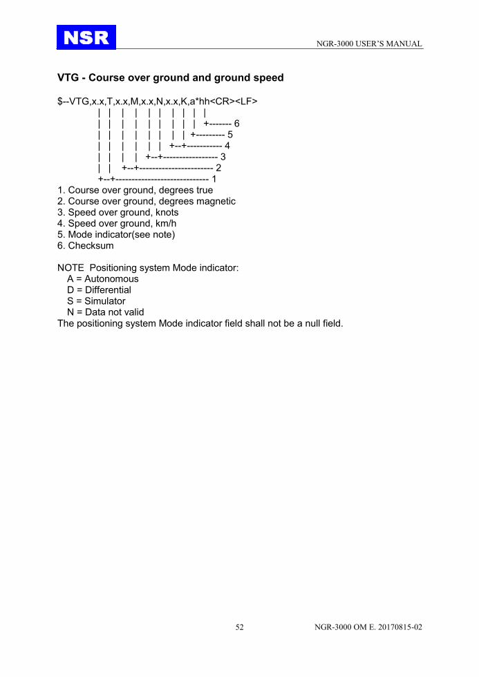
VTG - Course over ground and ground speed $--VTG,x.x,T,x.x,M,x.x,N,x.x,K,a*hh<CR><LF>
| | | | | | | | | | | | | | | | | | | +------- 6 | | | | | | | | +--------- 5 | | | | | | +--+----------- 4 | | | | +--+----------------- 3 | | +--+----------------------- 2 +--+----------------------------- 1
1. Course over ground, degrees true 2. Course over ground, degrees magnetic 3. Speed over ground, knots 4. Speed over ground, km/h 5. Mode indicator(see note) 6. Checksum NOTE Positioning system Mode indicator:
A = Autonomous D = Differential S = Simulator N = Data not valid
The positioning system Mode indicator field shall not be a null field.

NGR-3000 USER’S MANUAL
NGR-3000 OM E. 20170815-02 53
ZDA - Time and date $--ZDA,hhmmss.ss,xx,xx,xxxx,xx,xx*hh<CR><LF>
| | | | | | | | | | | | | +--------- 7 | | | | | +----------- 6 | | | | +-------------- 5 | | | +------------------ 4 | | +---------------------- 3 | +------------------------- 2 +--------------------------------- 1
1. UTC 2. Day, 01 to 31 (UTC) 3. Month, 01 to 12 (UTC) 4. Year (UTC) 5. Local zone hours, 00h to +-13h 6. Local zone minutes, 00 to +59
as local hours 7. Checksum

NGR-3000 USER’S MANUAL
NGR-3000 OM E. 20170815-02 54
APPEDIX IV INSTALLATION DRAWINGS


![t New CUBEs with Heavy Attitude t€¦ · METAL ZONE, EXTREME), GAIN Knob, VOLUME Knob, [EQUALIZER] BASS Knob, MIDDLE Knob, TREBLE Knob Indicators CLEAN Channel, LEAD Channel Connectors](https://static.documents.pub/doc/80x56/6067859789f730682b1d8a48/t-new-cubes-with-heavy-attitude-t-metal-zone-extreme-gain-knob-volume-knob.jpg)


![New t New CUBEs with Heavy Attitude t - American Musical Supply · 2013. 11. 26. · METAL ZONE, EXTREME), GAIN Knob, VOLUME Knob, [EQUALIZER] BASS Knob, MIDDLE Knob, TREBLE Knob](https://static.documents.pub/doc/80x56/6067859789f730682b1d8a47/new-t-new-cubes-with-heavy-attitude-t-american-musical-supply-2013-11-26.jpg)

