1 Important: This paper consists of 50 questions in 12 pages. Answer all questions. Write your index number in the space provided on the answer sheet. choose the correct or most appropriate answer from the amswers numbered (1) , (2) , (3) , (4) , (5) for each question from 1 to 50 and put a cross (X) according to the instructions given in the answer sheet 01. Which of the following is not equivalent to the unit of surface tension? (1) N m -1 (2) J m -2 (3) kg m -2 (4) kg s -2 (5) W m -2 s 02. An experimental set up used by a student to measure the diameter of a beaker is shown above. The diameter derived from the measurement is (1) 3.5 cm (2) 4 cm (3) 4.5 cm (4) 5cm (5) 8 cm 03. The above figure shows the wave fronts of the sound waves produced by an aero plane in three different instances during a horizontal fly. The Mach number and the directions of the movement in these three instances respectively are (1) Equal to one, lesser than one, greater than one, right hand side in three instances (2) Greater than one, equal to one, lesser than one, right hand side in three instances (3) Greater than one, equal to one, lesser than one, left hand side in three instances (4) Lesser than one, equal to one, greater than one, right hand side in three instances (5) Lesser than one, equal to one, greater than one, left hand side in three instances Use of calculator is prohibited (g = 10 N kg -1 ) Physics-I ngsjpftpay; -I Scale Wooden bar Beaker
Transcript
1
Important:
This paper consists of 50 questions in 12 pages.
Answer all questions.
Write your index number in the space provided on the answer sheet.
choose the correct or most appropriate answer from the amswers numbered (1) , (2) , (3) , (4) , (5) for each
question from 1 to 50 and put a cross (X) according to the instructions given in the answer sheet
01. Which of the following is not equivalent to the unit of surface tension?
(1) N m-1 (2) J m-2 (3) kg m-2 (4) kg s-2 (5) W m-2 s
02.
An experimental set up used by a student to measure the diameter of a beaker is shown above. The
diameter derived from the measurement is
(1) 3.5 cm (2) 4 cm (3) 4.5 cm (4) 5cm (5) 8 cm
03.
The above figure shows the wave fronts of the sound waves produced by an aero plane in three different
instances during a horizontal fly. The Mach number and the directions of the movement in these three
instances respectively are
(1) Equal to one, lesser than one, greater than one, right hand side in three instances
(2) Greater than one, equal to one, lesser than one, right hand side in three instances
(3) Greater than one, equal to one, lesser than one, left hand side in three instances
(4) Lesser than one, equal to one, greater than one, right hand side in three instances
(5) Lesser than one, equal to one, greater than one, left hand side in three instances
Use of calculator is prohibited
(g = 10 N kg-1)
Physics-I
ngsjpftpay;-I
Scale
Wooden bar
Beaker
2
04. In which of the following instance/ process, photo electric effect does not not happen?
which of the following is suitable for those steps?
First step
Second step
(1) β- emmision neutron- emmision
(2) β- emmision α- emmision
(3) β- emmision γ- emmision
(4) Deutron- emmision two neutron- emmision
(5) α- emmision γ- emmision
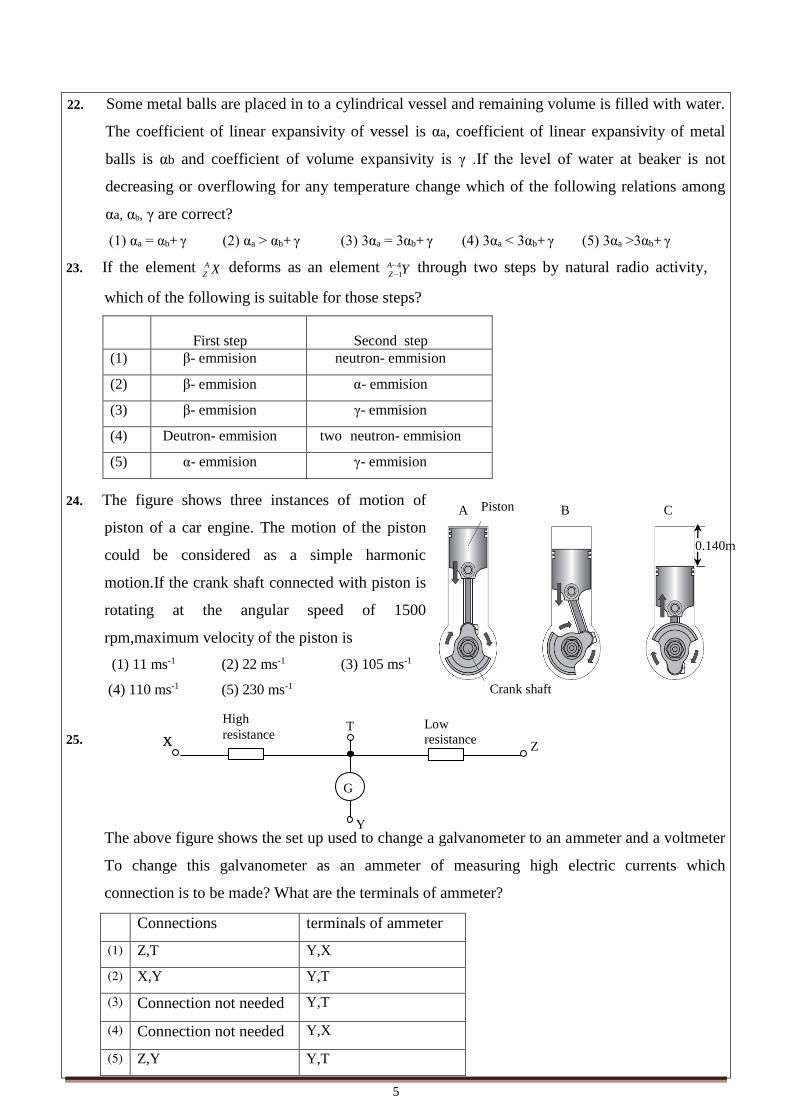
24. The figure shows three instances of motion of
piston of a car engine. The motion of the piston
could be considered as a simple harmonic
motion.If the crank shaft connected with piston is
rotating at the angular speed of 1500
rpm,maximum velocity of the piston is
(1) 11 ms-1 (2) 22 ms-1 (3) 105 ms-1
(4) 110 ms-1 (5) 230 ms-1
25.
The above figure shows the set up used to change a galvanometer to an ammeter and a voltmeter
To change this galvanometer as an ammeter of measuring high electric currents which
connection is to be made? What are the terminals of ammeter?
Connections terminals of ammeter
(1) Z,T Y,X
(2) X,Y Y,T
(3) Connection not needed Y,T
(4) Connection not needed Y,X
(5) Z,Y Y,T
T High
resistance Low
resistance
X X
Y
Z
G
Piston
Crank shaft
A B C
0.140m
6
26. A girl is moving on a diving board from A towards the
other end of the board .Which of the follwing graph
shows the variation of reaction F given by the support
to the board.(The board is able to rotate freely about A)
27.
A room consists of two windows A and B with equal cross sectional area.Window A consist a
glass of thickness 4cm.Window B consists two very thin glass layers at 2mm gap and the gap is
filled with air.Thermal conductivity of glass and air is 0.8Wm-10C-1 ,0.025Wm-1 0C-1respectively
(1) 2 (2) 4 (3) 8 (4) 16 (5) 32
28. A parallel laser beam coming from He,Ne laser has 1mm diameter.This beam is sent through a
convex lens of focal length 1.5cm inorder to get a parallel beam of diameter 10 mm, the focal
lenth of second lens to be used and the distance from the first lens is
Focal lenth
lenth
(1) 4.5cm 6.0cm
(2) 10cm 10.0cm
(3) 10cm 11.5cm
(4) 15cm 15.0cm
(5) 15cm 16.5cm
F
x
F
x
F
x
F
x
F
x
(1) (2) The
ratio
betw
een
the
heat
flow
thro
ugh
the
wind
ow
A
Heat
flow
thro
ugh
the
wind
ow
B
(3) (4) (5)
Weight of the girl
A
Glass
Glass Outside Inside
4mm
Window A
Air Outside
Inside
Glass
2mm
Window B
The rate of heat flow through the window A
The rate of heat flow through the window B
The ratio
7
B A C
P Q
29. From two points at separation of 50m in a horizontal ground, two balls A, B are thrown towards
each other. Ball A is thrown with speed 20ms-1at an inclination of 30 0upwards and another ball
B is thrown with speed 20 ms-1 at an inclination of 600 in the same plane. Which of the
following statements is/are correct about the motion of the balls until they reach the ground?
(1) Velocity of B relative to A increases with time
(2) Velocity of B relative to A increases with time
(3) Two balls will collide with each other during the motion
(4) When the both balls are at same vertical line ball A will be above ball B
(5) When the both balls are at same vertical line ball B will be above ball A
30. Two current carrying parallel conductors P, Q are kept
perpendicularly to the plane of sheet where three magnetic
pins A, B, C are kept. If the current through Q is reversed
what will happen to the directions of magnetic pins?
(1) directions of A,B,C will change
(2) directions of A,B,C will not change
(3) direction of C will change
(4) directions of A,B will not change
(5) directionsof B,C may change
31. The word physics on the sheet is 14mm height. It is observed through
a convex lens of focal length 16 cm and it is seems like in the nearby
figure. If the height of the image formed by the lens is 56mm,the
distance between the lens and the sheet is
(1) 12 cm (2) 16cm (3) 20cm
(4) 22cm (5) 40cm
32. A ball releasing from a point above the horizontal floor , collide on the floor, bounces and rises
again and again.Which of the following graph correctly shows the variation of its speed with
time graph?
(1) (2) (3)
(4) (5)
Time
Speed Speed
Time
Speed
Time
Speed Speed
Time Time
8
33. A rectangular coil of A cross sectional area and N
number of turns is kept inside a uniform magnetic
field. When the coil is rotated about the axis XY with
a constant angular frequency. The maximum electro
motive force induced in the coil is E0.The magnetic
field intensity is of that magnetic field is
NAf
Eo
2)1(
NAf
Eo
)2(
f
Eo
2)3(
f
Eo
)4(
ofE2)5(
34. One end of a string is connected at a post and able to move.The figure
shows an instance of a pulse moving right handside along the
string.Which of the following graph correctly shows the vertical
displacement (s) with time?
35. Directions of the motion of sound source (S) and the observer (O) at different instances are given below.
sound source (S) observer (O)
a
b
c
d
Connect the above instances with the below predictions
f-frequency felt by observer ,fo-frequency of the source
f>fo f<fo Can’t predict
(1) c and d a b
(2) a and b c d
(3) d c a and b
(4) c d a and b
(5) c a b and d
36. The following set up is used to verify force parallelogram
law.the length of the diagonal of the parallegram gain in the
paper is 4cm .The relative density of X is 8.If X is totally
immersed under the water and the experiment is done again
then value of L is
(1) 2.4cm (2) 2.8cm (3) 3.2cm (4) 3.5cm (5) 3.8cm
X
X
m1g m2g
Direction
of
magnetic
field
(1) (2) (3) (4) (5)
s
t
s
t
s
t
s
t
s
t
9
37.
The capacitor shown in thefigure(1) is fully charged by touching the switch S at a. At t=0if
the switch is made to touch at b,which of the following graph will correctly shows the
variation of current passing through the resistance?
(1) A (2) B (3) C (4) D (5) E
38.
Two identical masses P,Q are kept at same horizontal level on two smooth inclined planes
inclined at angles A,B which are kept at same horizontal floor and let to move at same time.
The ratio between the times to attain same horizontal displacements TP/TQ is?
)cos()sin(
)cos()sin()1(
BB
AA
)cos()sin(
)cos()sin()2(
AA
BB
B
A
sin
sin)3(
A
B
sin
sin)4(
)cos()sin(
)cos()sin()5(
AA
BB
39. Two AND gates are connected as shown in the figure.consider the following combinatios for
logical levels for the inputs Q1,Q2
Logical level of Q1 logical level of Q2
(A) 0 0
(B) 0
1
(C) 1
0
(D) 1
1
Which of the above combinations will give stable logical levels for the inputs Q1,Q2?
(1) (A) only (2) (D) only (3) (A),(B) only (4) (A),(D) only (5) (B),(C) only
40. When we put a copper below in to the water it was sunk. And when we put copper scrapings,
they were float.Which of the following statement/statements is/ are correct?
(A) The weight of the displaced water is less than the weight of copper block
(B) The weight of displaced water is equal to the weight of the copper block
(C) When change copper block into scrapings, its volume increases
(1) (A) only (2) (A), (B) only (3) (A),(C) only (4) (B),(C) only (5) All (A),(B),(C)
Q1 Q2
figure (2)
a b
s r
R C
V
figure(1)
A B
Q P
10
41.
the figure shows the wave pattern of a cathode ray
oscilloscope which is connected across the points
R,S in the electric circuit drawn in the above
figure.If the circuit is changed as shown in the
nearby figure below,the correct graph shows the
variation of output (Vout) with time is
42. The variation of temperature of two liquid samples of equal volume
which are taken in two identical vessels at same environment and
heated by identical heaters is shown in the nearby graph.The
conclusions you may attain from this graph is
(A) Specific heat capacity of A is greater than the specific heat
capacity of B
(B) Liquid B attained the boiling point
(C) Liquid A attained the boiling point
(1) (A) only (2) (B) only (3) (C) only (4) (B),(C) only (5) All (A),(B),(C) ;
43. A closed cylindrical vessel filled with water is pulled with an
acceleration a. the figure shows the longitudinal section of the
vessel. If the pressure at the points A, B which are at the separation
d is PA,PB. Which of the following statrement/statements is/are true?
(A) when the depth from the upper level increases the pressure
differences between the points A,B will increase
(B) the resultant force by the liquid exerted on the base of the vessel is at the center of the
base
(C) resultant force exterted on the wall of the vessel goes through the center of the vessel
(1) (A) only (2) (B) only (3) (C) only (4) (B),(C) only (5) Non of the obove
Vout
t
Vout
t
Vout
t
Vout
t
Vout
t
(1) (2) (3) (4) (5)
d
h
a B A
LiquidA
LiquidB
Time
Temperature
11
44. The following circuit is made up of a silicon diode and a Zenor diode of
breaking voltage 5V and some resistors. if the electric currents through
the branches are I1,I2,I3,I4,which of the following relation is correct?
(1) I1>I3> I2>I4≠ 0
(2) I1>I3> I2>I4=0
(3) I1>I2= I3=I4 ≠ 0
(4) I1>I2=I3>I4 ≠ 0
(5) I1>I2=I3>I4=0
45. A circuit is made by some resistances and batteries as shown
in the figure .Current through the battery of electro motive
force E is
(1) 1A (2) 2A (3) 3A
(4) 4A (5) 5A
46. The following graph shows the variation of two quantities X,Y
related with a moving particle with time t .which of the following
may suitable for X and Y
(A) X may be the mechanical energy of an object moving downwards in a
smooth inclined plane and Y may be the linear kinetic energy of the
particle
(B) X may be the kinetic energy of a particle slipping downwards in a inclined plane and Y
may be the work done on the object by the resistive forces
(C) X may be the resultant force acting on the object and Y may be the velocity of the
particle
Which of the above is /are correct? (1) (A) only (2) (A), (B) only (3) (A),(C) only (4) (B),(C) only (5) All (A),(B),(C)
47. A rectangular loop shown in the figure is kept coplanar with a long wire carrying current I. The
loop is pulled in the right hand side direction. Which of the following answers correctly gives
the direction of induced current and the directions of the forces acting on the left, right hand
sides of the loop?
Induced current force acting on
left hand side force acting on
left hand side (1) Anticlockwise
towards left towards right
(2) Anticlockwise
towards left towards left
(3) Anticlockwise
towards right towards left
(4) Clockwise towards right towards left
(5) Clockwise towards left towards right
t
X
Y
m
t
A
B
I1
I2
I3
I4
Vz=5
V
10V R
R
R
R
-5V
1A
E
3A
5A
1A
2Ω
2Ω
4Ω
2Ω
2Ω
4Ω 2Ω
4Ω
I
12
48. Two identical vessels having equal volume of water are kept upon two
identical electronic balances and kept inside two closed rooms of equal
volume at temperature 300C and 400C respectively. When observed from
outside the readings of the electronic balances are varied as shown in the
figure. Which of the following statement/statements is/are correct?
(A) At initial the absolute humidity of A is less than that of B
(B) Room A is finally saturated with water vapour
(C) If rooms A and B are connected with a window, water vapour will transfer from A to B
(1) (A) only (2) (A), (B) only (3) (A), (C) only (4) (B),(C) only (5) All (A),(B),(C)
49.
The figure shows two spherical spheres immersed inside a symmetric vessel filled with water.
The pegs are located at equal distances from the edges. The figure shows the longitudinal section
along the diameter consist the pegs and the spherical particles. The spherical spheres of equal
volume and densities d1,d2 are tied and let to float at the distances of l1,l2 from the centre.If the
reactions given by the pegs are equal, the ratio of l1/l2(the density of water is dw)
2
1)1(d
d
1
2)2(d
d
2
1)3(dd
dd
w
w
1
2)4(dd
dd
w
w
w
w
dd
dd
2
1)5(
50.
A rectangular region consist of outward uniform magnetic field in the direction perpendicular to
the sheet and downward electric field E along the sheet .The path of four particles P,Q,R and
with equal magnitude of charge entering into the region from equal distances from the vertices.
If the kinetic energies of those particles when exit from this region are Ep ,Eq,Er ,Es the correct
relations among them is
(1) Ep =Eq=Er =Es (2) Ep =Eq=Es >Er (3) Eq>Er > Ep =Es (4) Ep =Eq>Er >Es (5) Eq =Es>Er >Ep
RA RB l1 l2
P
R
S
Q
a
a
a
a
E E
A
B
m
t
AL/2015/01/E-II ~ 1 ~
[ See page 02
Ôity of Moratuwa, Faculty of Engineering. Tamil students,Tamil student, University of Moratuwa, Faculty of Engineering. Tamil students, Tamil student, University of Moratuwa, Faculty of Engineering.
ìamil students, University of Moratuwa, Faculty of Engineering. Tamil students,Tamil student, University of Moratuwa, Faculty of Engineering. Tamil students, Tamil student, University of Moratuwa, Faculty of Engineering. Tamilstudents,
samil students, University of Moratuwa, Faculty of Engineering. Tamil students,Tamil student, University of Moratuwa, Faculty of Engineering. Tamil students, Tamil student, University of Moratuwa, Faculty of Engineering.Tamil students,
Tamil students, UniverÔity of Moratuwa, Faculty of Engineering. Tamil students,Tamil student, University of Moratuwa, Faculty of Engineering. Tamil students, Tamil student, University of Moratuwa, Faculty of Engineering.Tamil students,
samil students, University of Moratuwa, Faculty of Engineering. Tamil students,Tamil student, University of Moratuwa, Faculty of Engineering. Tamil students, Tamil student, University of Moratuwa, Faculty of Engineering.Tamil students,
ìamil students, University of Moratuwa, Faculty of Engineering. Tamil students,Tamil student, University of Moratuwa, Faculty of Engineering. Tamil students, Tamil student, University of Moratuwa, Faculty of Engineering. Tamilstudents,
samil students, University of Moratuwa, Faculty of Engineering. Tamil students,Tamil student, University of Moratuwa, Faculty of Engineering. Tamil students, Tamil student, University of Moratuwa, Faculty of Engineering.Tamil students,
Tamil students, UniverTamil students,
Tamil students, University of Moratuwa, Faculty of Engineering. Tamil students,Tamil student, University of Moratuwa, Faculty of Engineering. Tamil students, Tamil student, University of Moratuwa, Faculty of Engineering.Tamil students,
Part - A Structured Essay Answer all four questions on this paper itself
(g= 10 N kg -1)
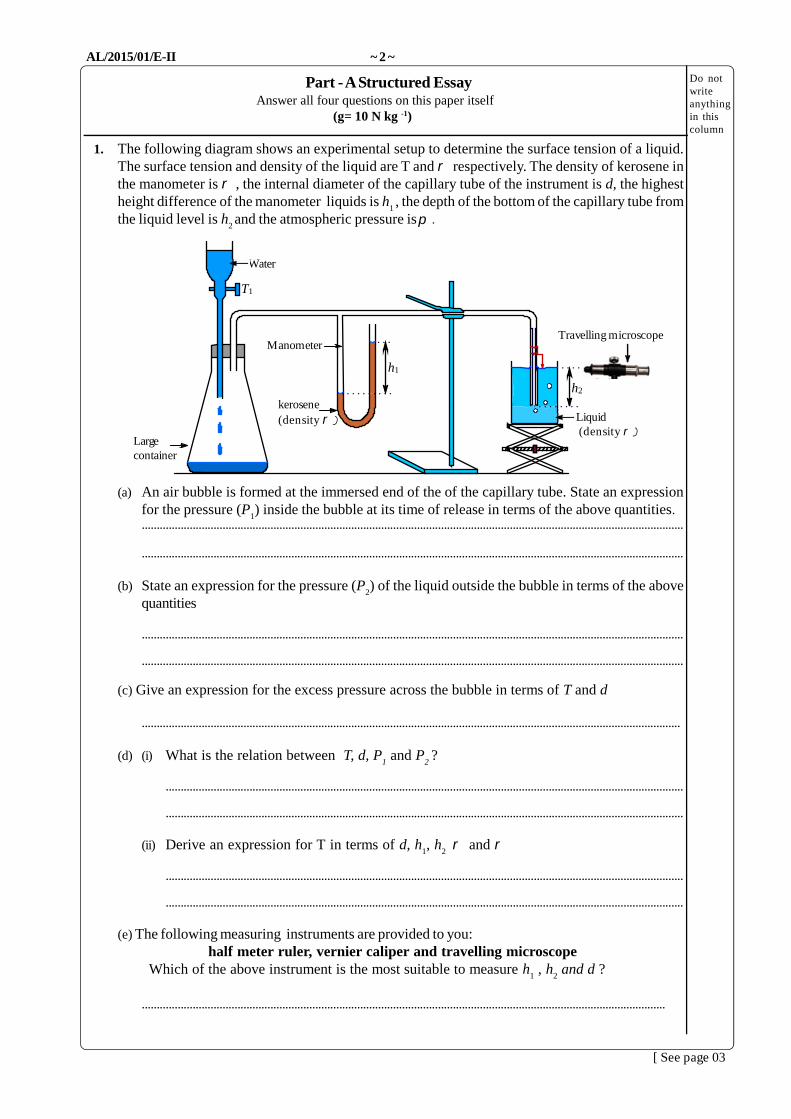
1. The following diagram shows an experimental setup to determine the surface tension of a liquid.The surface tension and density of the liquid are T and respectively. The density of kerosene inthe manometer is , the internal diameter of the capillary tube of the instrument is d, the highestheight difference of the manometer liquids is h
1, the depth of the bottom of the capillary tube from
the liquid level is h2and the atmospheric pressure is .
(a) An air bubble is formed at the immersed end of the of the capillary tube. State an expressionfor the pressure (P
1) inside the bubble at its time of release in terms of the above quantities.
(g) The pressure inside the capillary tube of diameter 4 X 10⁻⁴m was increased and measuredusing a manometer. An air bubble is formed at the end of the capillary tube as a result of theincrement of the pressure. The height difference between the levels of the liquids in themanometer when the bubble tends to break is 9x10 -2m. The lower end of the capillary tubewas at a depth of 2.5x10- 2m below the liquid level. The densities of the liquids in the vessel andmanometer are 800 kgm-3 and 900 kgm-3 respectively. Calculate the surface tension of theliquid in the vessel.
2. An experimental setup to investigate the variation of pressure (p)with volume (V) of dry air at constant temperature is shown in thefigure.(a) What is the disadvantage in using water thread instead of
An experimental setup to determine the focal length of aconcave lens is shown in the figure above. First a straight line isdrawn on the table using a chalk. Lens fixed to a stand is placedon the mid point of the line such that the plane of the lens isperpendicular to the line. Then a screen is placed as shown inthe figure. The following materials are given to find the virtualimage of a real object.
(a) Complete the experimental setup using the provided objects.
(b) Indicate the places where the images are formed in the above setup.
(c) Write down the experimental procedures in the correct order.
(f) State an equation to find the focal length by using a straight line graph, in terms of objectdistance (u), image distance (v) and focal length (f). Mention the dependent and independentvariable.
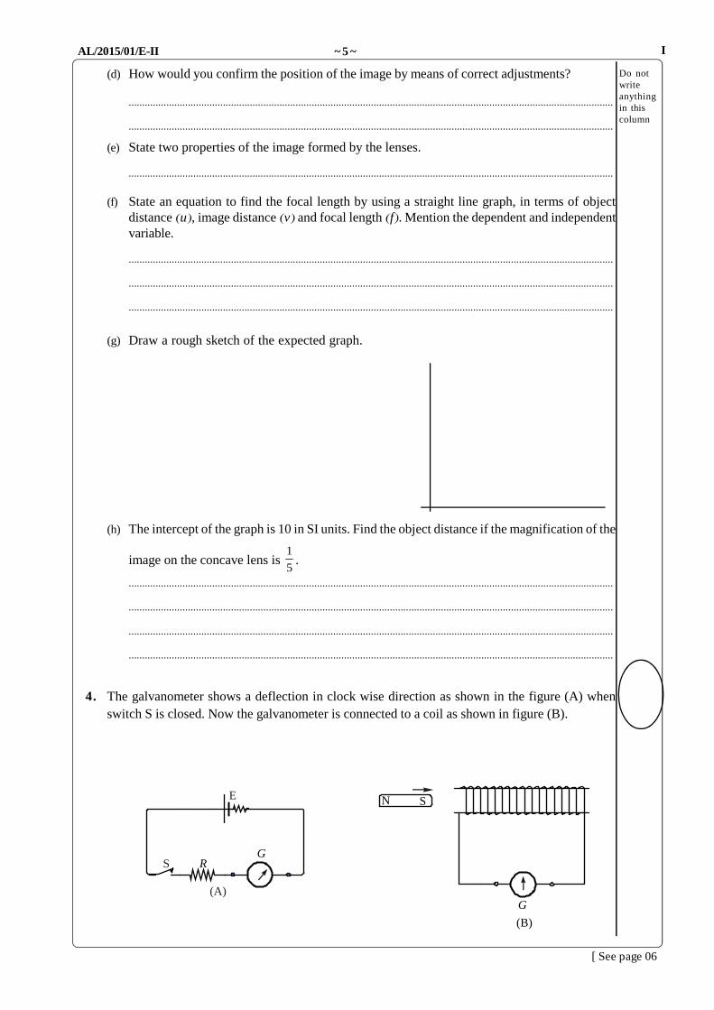
4. The galvanometer shows a deflection in clock wise direction as shown in the figure (A) whenswitch S is closed. Now the galvanometer is connected to a coil as shown in figure (B).
I
[ See page 06
E
GRS
(A)G
SN
(B)
AL/2015/01/E-II ~ 6 ~
Core
SG
Do notwriteanythingin thiscolumn
(a) Now the south pole of the bar magnet is moved quickly towards the coil. What will be thedirection of deflection of the galvanometer?
(d) A simple structure of a transformer is shown in the figure.(i) Underline which of the following is the most suitable material to be used as the core.
A - solid soft iron coreB - insulated copper platesC - insulated soft iron core
(ii) State the reason why the other materials are not suitable.
(f) For the variation of voltage difference in the primary coil with time as shown in figure (I) drawthe graph for the corresponding voltage difference of secondary coil with time in figure (II),when the switch S is opened and closed at equal interval of time.
(g) By using transformers the voltage difference of the sign waves can be increased or decreased. But
alternative current of square wave form cannot be stepped-up or stepped-down. Give reasons.
(h) The number of turns in primary and secondary coils are 6000 and 600 respectively. When analternate current voltage of 240 V is applied to the primary coil what will be the voltage at thesecondary coil?
5. Most of the motions in nature include linear and rotational motions.(a) (i) Figure (1) shows a woman with weight W who is running along
a circular path with velocity v. Copy the diagram in youranswer sheet, denote the two forces exerted on her foot bythe ground and name them. Mention separately which isresponsible for providing those forces.
(ii) Draw the resultant force acting on her foot and denote hercentre of gravity (G) approximately. What is the reason fordenoting it in that position?
(iii)While running she would be inclined towards the centre of thecircular path. What is the reason for that?
(b) (i) If her weight is W, velocity is v, resultant force exerted by the ground is Fr and angle of inclination
with vertical is , find the horizontal and vertical components of the resultant force in terms ofradius of the circular path R, W and v. From this obtain an expression for tan.
(ii) If the radius of the circular path is 15m and running speed is 7ms-1, find the angle of inclination to the vertical.
(c) (i) Most of the body movements while walking (as in figure 2) and runningcan be explained with the help of simple harmonic motion. Each stepmade by the foot can be considered approximately as half theoscillation period of simple harmonic motion. If a man is able to walk ata speed of 2 steps per second and he moves 90cm for every single step,what is his speed of walking?
(ii) What is the maximum speed of the oscillating foot while walking?Compared to the speed of walking approximately how many times isthe maximum speed?
(iii)What is the maximum acceleration of the oscillating foot? Compared tothe gravitational acceleration how many is this maximum acceleration?
(d) (i) While running (as shown in figure 3), legs not only rotate about thehip joint but also rotate about the knee joint. But as the oscillationabout the hip joint is prominent, considering the rotation about thehip joint only mention which provides the required energy to runwith the help of oscillating legs.
(ii) If the moment of inertia of the leg about the hip is I and the highestangular velocity of the foot while oscillating is
max, mention where
does this highest velocity is achieved (A or B) and obtain an expression for the maximum rotational kinetic energy. Does thisenergy provide the required energy for running? Explain.
[ See page 09
Figure (1)
Figure (2)
B
A
Figure (3)
Ôity of Moratuwa, Faculty of Engineering. Tamil students,Tamil student, University of Moratuwa, Faculty of Engineering. Tamil students, Tamil student, University of Moratuwa, Faculty of Engineering.
ìamil students, University of Moratuwa, Faculty of Engineering. Tamil students,Tamil student, University of Moratuwa, Faculty of Engineering. Tamil students, Tamil student, University of Moratuwa, Faculty of Engineering. Tamilstudents,
samil students, University of Moratuwa, Faculty of Engineering. Tamil students,Tamil student, University of Moratuwa, Faculty of Engineering. Tamil students, Tamil student, University of Moratuwa, Faculty of Engineering.Tamil students,
Tamil students, UniverÔity of Moratuwa, Faculty of Engineering. Tamil students,Tamil student, University of Moratuwa, Faculty of Engineering. Tamil students, Tamil student, University of Moratuwa, Faculty of Engineering.Tamil students,
samil students, University of Moratuwa, Faculty of Engineering. Tamil students,Tamil student, University of Moratuwa, Faculty of Engineering. Tamil students, Tamil student, University of Moratuwa, Faculty of Engineering.Tamil students,
ìamil students, University of Moratuwa, Faculty of Engineering. Tamil students,Tamil student, University of Moratuwa, Faculty of Engineering. Tamil students, Tamil student, University of Moratuwa, Faculty of Engineering. Tamilstudents,
samil students, University of Moratuwa, Faculty of Engineering. Tamil students,Tamil student, University of Moratuwa, Faculty of Engineering. Tamil students, Tamil student, University of Moratuwa, Faculty of Engineering.Tamil students,
Tamil students, UniverTamil students,
Tamil students, University of Moratuwa, Faculty of Engineering. Tamil students,Tamil student, University of Moratuwa, Faculty of Engineering. Tamil students, Tamil student, University of Moratuwa, Faculty of Engineering.Tamil students,
6. (a) When waves travel from one medium to another, they involve to reflection or refraction. Consideringa longitudinal wave explain hard and soft reflections with the help of change in wave length,frequency and phase change of vibrating particles.
(b) A boy close to a well is producing a pulse from a sound source above the well on a day withenvironmental temperature 16oC. While observing the reflection of the pulse he heard two sounds.The time interval between the two sounds is 0.002s.(i) Find the depth of water in the well. (Velocity of the longitudinal wave in water is 1500ms-1)(ii) The sound which is heard first is of high intensity and it was observed 0.04s after vibrating the
sound source. If the speed of sound in air is 340ms-1, find the depth of the well.(iii) When the sound source is vibrated continuously, the incident ray and refracted ray from the
water form standing wave and it has been observed that the air column in the well is vibrating inthe first overtone. Find the frequency of the sound source.
(c) (i) On a day with environmental temperature 27oC, a boy drops a stone into the well. After how longwould he hear the sound from the instant the stone strikes the water?
(ii) If the stone is dropped in the middle of the well, the wave length of the formed circulartransitional wave is 1.8m. The velocity of this wave is given by ghv . Find the frequency ofthe wave.
.
7. (a) There is a small hole of radius r in the bottom of a vessel. A liquid is poured slowly into the vessel.Draw the figures representing the progress of the liquid bubble with the depth of the liquid h. Fromthis obtain an expression for h when the liquid starts to flow out through the hole in terms of densityof the liquid , surface tension T and radius of the hole r.
(b) X is an open hollow cylinder. Aweightless base PQ is in aposition as shown in the figuredue to the tension of an elasticstring. Assume that the liquiddoes not leak through the jointwhere the cylinder and the basejoin. AB is a 44cm long uniformtube of 1mm radius. A viscousliquid is collected in thecylindrical vessel underH cmHg pressure.
(i) There is a small hole of radius 1mm on PQ.The density and surface tension of the liquidare 10 kgm-3 and 0.5Nm-1 respectively. Findthe value of h when the liquid starts to flowout through the hole.
(ii) (a) If the volume of the liquid flowing through AB in one second is Q, write down Poiseuille’sequation for Q.
(b) If the viscosity of the liquid is 2 x 10⁻² Pa s and H = 70cm, find the time taken for the liquid toflow out through the hole from the instant the liquid flows into the vessel. The surface area ofthe base PQ is 10-2 m2.
(iii) The natural length of a rubber belt is 1m and its area of cross section is 10-6 m2. What is theextension that should be given to the belt to prevent the leakage of liquid through the joint beforeit flows out through the hole? (Young’s modulus of rubber is 5 x 10⁶ Pa)
I
[ See page 10
A B
X
P Q
Elasticstring
Elasticstring
H
l
h
AL/2015/01/E-II ~ 10 ~
8 Cathode ray oscilloscope (CRO) is an important electrostatis instrument in technological field. A simplediagram of cathode ray oscilloscope is shown.
It has a vacuum glass tube and a screen S coated with ZnS. The functions of some electrostaticcomponents are given below.
The electrons formed by heating the cathode (C) are accelerated by the anode A2
which is at a highpotential relative to cathode. Most of these electrons passes through the plates X,Y and hit the screen Scoated with ZnS. This screen emits green light due to fluorescence.
As the inside is coated with graphite, the region from A2
to S acts as equipotential region. As a result theelectron beam moves without any deflection and hit the screen with constant velocity. G is the brightnesscontrol grid. The potential at G is always negative relative to the cathode C and controls the amount ofelectrons. Therefore, the brghthess of light falling on the screen is alsocontrolled.
If we apply a varying potential difference across X plates as shown indiagram (B), the electron beam passing through it moves from left to right,then immediately to left. Process is repeated again and again due to afrequency based on time. The voltage can be altered by a time based knob.
Due to the electric field intensity created according to the variation of voltage difference between Y platesthe electron beam executes both horizontal and vertical motion. Due to this the variation of voltage of theform of electric signal, to measore small time ofifference and to observe the wave form of an audiblefrequency signal.
(a) (i) Why does the cathode ray tube is evacuated?(ii) Why does electric field is not created in the region with graphite?(iii) Why the intensity of fluorescense light decreases when the negative potential of G is increased?(iv) Between which plates does output signal has to be connected?
(b) (i) When observing through the eye, if the maximum time that can be memorized is 0.1s, find theminimum frequency that has to be applied between X plates to see the horizontal light beam.
(ii) When this frequency increases, draw the wave observed on screen when a 100 Hz sinusodiacvoltage is given.
(c) Find the final velocity of electrons when they are accelerated through a potential difference of 45V.( e = 1.610-19 C, m
e=910-31 kg)
The distance between Y plates is 4mm and the length of the plate is 4cm. Find the voltage that has to beapplied between Y plates for the electrons to exit without colliding with plates. (neglect the gravitationalforces)
I
[ See page 11
A1 A
2 Y XC G
S
cathode
controlgrid
converginganode
acceleratinganode Vacuum
electronbeam
Fluorescentscreen
Bright lightspot.
Y plate X plate
V
t
(B)
0
AL/2015/01/E-II ~ 11 ~
(d) While electrons travel in magentic field a force is created. Explain why that force cannot be used toaccelerate them in straight line.
9. Answer either part (A) or part (B) only.
(A) (a) Power is supplied to a load from a power supply of power P under voltage V. The resistance ofjoining wires when power is supplied to the load is R.
(i) Write an expression for the electric currentsupplied from the power supply.
(ii) Write an expression for the voltage differenceacross the load R
L
(iii) Obtain an expression for the power consumed inR
L
(iv) Write an expression for the power dissipated injoining wires.
(b) There are two types of buses which work by electric energy. One is autonomous which stores energy in batteries and works from it. Other one is non autonomous. It gets electrical energy from a power supply where electrical energy comes through one cable and goes through the other cable. Such a bus is shown below.
(i) Write an expression for the electric resistance of wires used in terms of cross section area A,length and resistivity .
(ii) Cross section area and resistivity are 5 10-3 m2 and 1.75 10-8 m-1 for an over heatedwire of length 1 km. Find its resistance.
(ii) Electric bus is joined to 250V supply. Electricity is supplied to the bus motor by wire andresistance of the track is negligible. Starting point of bus is near the power supply and thepower supply gives 67 kW power. Find the current passing through the motor of the bus.
(iii) Electric current in the circuit is 180A when the bus is at a distance of 30km from the powersupply. What is the potential difference applied for the motor of bus?
(iv) In this state what is the power absorbed by the motor?
(v) What percentage of power supplied from the power supply is used by bus?
I
[ See page 12
R
V RL
load
powersupply-ingregion
+
Electrically poweredbus
250 V
Track
+
overhead electric wires
AL/2015/01/E-II ~ 12 ~
(B) (a) (i) Draw the output characteristic (ID
vs VDS
) for the common source arrangement in JFETtransistor and name the active, saturation and cut off regions.
(ii) Which parameter is kept constant in labeling the curves above in (a)(i)?
(iii) In the (a)(i) above, which region/regions are suitable for amplification?
(b) Above circuit is an npn transistor amplifier circuit. Transistor is biased to supply voltage VCC
= +9V. Voltage of base relative to emitter is 0.6V. The base current and collector current are 20 Aand 2.98m A respectively. The collector potential relative to earth (V
BE) is 4.5V.
(i) What are the uses of capacitors C1 and C
2 ?
(ii) Calculate the value of resistance RB
(iii) Calculate resistance RC
(iv) Draw a graph showing the variation of collector current ICand V
Ccollector voltage with time
when a small input voltage signal is applied.(v) The output voltage (V
out) obtained in cathode ray oscilloscope is shown below. The height of a
small square represents 1V and its width represents 20 s. Find the following.
(1) Maximum value of output voltage.(2) Frequency of output voltage.
I
[ See page 13
RB
RC
VCC = +9 V
Vo
C1
C2
VC
iVi
t0
1 V
200 s
Voltage Measurement
Time Measurement
Vout
t
AL/2015/01/E-II ~ 13 ~
10. Answer either part (A) or part (B) only.(A) (a) The rate of heat flow perpendicular to a surface is given by
(i) Define each term.(ii) Give two conditions, under which the above equation is valid.
(b) When an athlete runs, heat is generated at a rate of 1000 kJ min-1. Moreover, internal bodytemperature increases to 44 oC. A portion of this heat flows perpendicular to the body muscle and isreleased to the environment. The average thickness of the muscle is 1cm, average surface area of thebody is 1.8 m2 and temperature of the external body surface is 34 oC. 1/5 portion of the heat generatedby the body is released through other ways and the remaining flows perpendicular to the muscle.(i) Calculate the average thermal conductivity of the muscle.(ii) What are the other methods through which the heat generated by the body is wasted?(iii) If the room temperature is 30 0C, calculate the cooling constant k.
(c)He is wearing a skinny tightly which is 1mm thick, covering his body surface completely. The thermalconductivity of the skinny is 1/4 of the body muscle. Moreover, its area is equal to the surface area ofthe body. The internal temperature is 44 0C and the temperature of the external surface of skinny is 310C. Assume that the heat loss due to other methods remains the same as earlier. Calculate theexternal body temperature now.
(d) There is a gap between the body and the skinny. Would the external body temperature be the same asin part (c)? Explain.
(e) While he is running without covering the body as much as possible, they will wet his body using water.What would you expect through this action?
(B) Photo electric effect is defined by the equation, hf = F + EK.Name the terms F and E
K. The experimental setup made by a
student to examine the photo electric effect is shown.
(a) Draw a sketch to show the variation of the potentialdifference (V ) across the electrodes with the photocurrent (I ) for the light with constant intensity andfrequency.(1) When increasing the frequency without changing the
intensity(2) When doubling the light intensity without changing the
frequencyDraw the expected variation of I with V on the abovesketch. Name the condition (1) as X and condition (2)as Y.
The stopping potential VS for two values of wave-
length l was measured. It is denoted in the givenV
Svs l graph.Here, stopping potential is the suffi-
cient potential for preventing the electrons fromreaching the anode.(b) What is the maximum kinetic energy of the
photo electrons, when a radiation of wave-length 380nm falls on a radiative metal sur-face?
(c) What is the energy of photon of wavelength380nm?
(d) Calculate the work function of the metal.(e) Calculate the threshold wavelength.(f) Explain why the threshold wavelength of the metal could not be deduced from the data in the above
graph.(Planck’s constant h = 6.63510-34 J s, velocity of light c = 3108 m s-1 charge of electron e = 1.610-19 C)