___________ (x) R16PS01019 x x 5 copies of the amendment; (b) By acknowledging receipt of this amendment on each copy of the offer submitted ; or (c) By separate letter or telegram which includes a reference to the solicitation and amendment numbers. FAILURE OF YOUR ACKNOWLEDGEMENT TO BE RECEIVED AT THE PLACE DESIGNATED FOR THE RECEIPT OF OFFERS PRIOR TO THE HOUR AND DATE SPECIFIED MAY RESULT IN REJECTION OF YOUR OFFER. If by virtue of this amendment you desire to change an offer already submitted , such change may be made by telegram or letter, provided each telegram or letter makes reference to the solicitation and this amendment, and is received prior to the opening hour and date specified. x Salt Lake City UT 84138 R40 125 South State Street, Room 8100 Regional Office Upper Colorado Region Bureau of Reclamation 07/28/2016 000003 2 1 13. THIS ITEM ONLY APPLIES TO MODIFICATION OF CONTRACTS/ORDERS. IT MODIFIES THE CONTRACT/ORDER NO. AS DESCRIBED IN ITEM 14. 12. ACCOUNTING AND APPROPRIATION DATA (If required) is not extended. is extended, Items 8 and 15, and returning Offers must acknowledge receipt of this amendment prior to the hour and date specified in the solicitation or as amended , by one of the following methods: (a) By completing The above numbered solicitation is amended as set forth in Item 14. The hour and date specified for receipt of Offers 11. THIS ITEM ONLY APPLIES TO AMENDMENTS OF SOLICITATIONS FACILITY CODE CODE 10B. DATED (SEE ITEM 13) 10A. MODIFICATION OF CONTRACT/ORDER NO. 9B. DATED (SEE ITEM 11) 9A. AMENDMENT OF SOLICITATION NO. CODE 8. NAME AND ADDRESS OF CONTRACTOR (No., street, county, State and ZIP Code) 7. ADMINISTERED BY (If other than Item 6) CODE 6. ISSUED BY PAGE OF PAGES 4. REQUISITION/PURCHASE REQ. NO. 3. EFFECTIVE DATE 2. AMENDMENT/MODIFICATION NO. 5. PROJECT NO. (If applicable) 1. CONTRACT ID CODE AMENDMENT OF SOLICITATION/MODIFICATION OF CONTRACT 06/23/2016 CHECK ONE A. THIS CHANGE ORDER IS ISSUED PURSUANT TO: (Specify authority) THE CHANGES SET FORTH IN ITEM 14 ARE MADE IN THE CONTRACT B. THE ABOVE NUMBERED CONTRACT/ORDER IS MODIFIED TO REFLECT THE ADMINISTRATIVE CHANGES (such as changes in paying office, C. THIS SUPPLEMENTAL AGREEMENT IS ENTERED INTO PURSUANT TO AUTHORITY OF: D. OTHER (Specify type of modification and authority) appropriation date, etc.) SET FORTH IN ITEM 14, PURSUANT TO THE AUTHORITY OF FAR 43.103(b). E. IMPORTANT: Contractor is not, is required to sign this document and return __________________ copies to the issuing office. ORDER NO. IN ITEM 10A. 14. DESCRIPTION OF AMENDMENT/MODIFICATION (Organized by UCF section headings, including solicitation/contract subject matter where feasible.) The purpose of AMENDMENT 000003 is as follows: 1. To post revised Specifications to the following sections: 33 11 10 - Pipeline General Requirements 33 11 12 - Steel Line Pipe 33 11 16 - PVC Pressure Pipe 33 11 18 - HDPE Pressure Pipe 33 11 19 - Fiberglass Pipe Please see Attachment 1. Continued ... 16A. NAME AND TITLE OF CONTRACTING OFFICER (Type or print) 15A. NAME AND TITLE OF SIGNER (Type or print) 15C. DATE SIGNED 16B. UNITED STATES OF AMERICA 15B. CONTRACTOR/OFFEROR 16C. DATE SIGNED (Signature of person authorized to sign) (Signature of Contracting Officer) Jared F. Van Buskirk STANDARD FORM 30 (REV. 10-83) Prescribed by GSA FAR (48 CFR) 53.243 NSN 7540-01-152-8070 Previous edition unusable Except as provided herein, all terms and conditions of the document referenced in Item 9 A or 10A, as heretofore changed, remains unchanged and in full force and effect .
Transcript
___________
(x)
R16PS01019
x
x
5 copies of the amendment; (b) By acknowledging receipt of this amendment on each copy of the offer submitted ; or (c) By
separate letter or telegram which includes a reference to the solicitation and amendment numbers. FAILURE OF YOUR ACKNOWLEDGEMENT TO BE RECEIVED AT
THE PLACE DESIGNATED FOR THE RECEIPT OF OFFERS PRIOR TO THE HOUR AND DATE SPECIFIED MAY RESULT IN REJECTION OF YOUR OFFER. If by
virtue of this amendment you desire to change an offer already submitted , such change may be made by telegram or letter, provided each telegram or letter makes
reference to the solicitation and this amendment, and is received prior to the opening hour and date specified.
x
Salt Lake City UT 84138
R40
125 South State Street, Room 8100Regional OfficeUpper Colorado RegionBureau of Reclamation
07/28/2016000003
21
13. THIS ITEM ONLY APPLIES TO MODIFICATION OF CONTRACTS/ORDERS. IT MODIFIES THE CONTRACT/ORDER NO. AS DESCRIBED IN ITEM 14.
12. ACCOUNTING AND APPROPRIATION DATA (If required)
is not extended.is extended,
Items 8 and 15, and returning
Offers must acknowledge receipt of this amendment prior to the hour and date specified in the solicitation or as amended , by one of the following methods: (a) By completing
The above numbered solicitation is amended as set forth in Item 14. The hour and date specified for receipt of Offers
11. THIS ITEM ONLY APPLIES TO AMENDMENTS OF SOLICITATIONS
FACILITY CODE CODE
10B. DATED (SEE ITEM 13)
10A. MODIFICATION OF CONTRACT/ORDER NO.
9B. DATED (SEE ITEM 11)
9A. AMENDMENT OF SOLICITATION NO.
CODE
8. NAME AND ADDRESS OF CONTRACTOR (No., street, county, State and ZIP Code)
7. ADMINISTERED BY (If other than Item 6)CODE 6. ISSUED BY
1. CONTRACT ID CODEAMENDMENT OF SOLICITATION/MODIFICATION OF CONTRACT
06/23/2016
CHECK ONE A. THIS CHANGE ORDER IS ISSUED PURSUANT TO: (Specify authority) THE CHANGES SET FORTH IN ITEM 14 ARE MADE IN THE CONTRACT
B. THE ABOVE NUMBERED CONTRACT/ORDER IS MODIFIED TO REFLECT THE ADMINISTRATIVE CHANGES (such as changes in paying office,
C. THIS SUPPLEMENTAL AGREEMENT IS ENTERED INTO PURSUANT TO AUTHORITY OF:
D. OTHER (Specify type of modification and authority)
appropriation date, etc.) SET FORTH IN ITEM 14, PURSUANT TO THE AUTHORITY OF FAR 43.103(b).
E. IMPORTANT: Contractor is not, is required to sign this document and return __________________ copies to the issuing office.
ORDER NO. IN ITEM 10A.
14. DESCRIPTION OF AMENDMENT/MODIFICATION (Organized by UCF section headings, including solicitation/contract subject matter where feasible.)
The purpose of AMENDMENT 000003 is as follows:
1. To post revised Specifications to the following sections:
33 11 10 - Pipeline General Requirements
33 11 12 - Steel Line Pipe
33 11 16 - PVC Pressure Pipe
33 11 18 - HDPE Pressure Pipe
33 11 19 - Fiberglass Pipe
Please see Attachment 1.
Continued ...
16A. NAME AND TITLE OF CONTRACTING OFFICER (Type or print)15A. NAME AND TITLE OF SIGNER (Type or print)
15C. DATE SIGNED 16B. UNITED STATES OF AMERICA 15B. CONTRACTOR/OFFEROR 16C. DATE SIGNED
(Signature of person authorized to sign) (Signature of Contracting Officer)
Jared F. Van Buskirk
STANDARD FORM 30 (REV. 10-83)
Prescribed by GSA
FAR (48 CFR) 53.243
NSN 7540-01-152-8070
Previous edition unusable
Except as provided herein, all terms and conditions of the document referenced in Item 9 A or 10A, as heretofore changed, remains unchanged and in full force and effect .
ITEM NO. SUPPLIES/SERVICES QUANTITY UNIT UNIT PRICE AMOUNT
NAME OF OFFEROR OR CONTRACTOR
2 2CONTINUATION SHEET
REFERENCE NO. OF DOCUMENT BEING CONTINUED PAGE OF
(A) (B) (C) (D) (E) (F)
R16PS01019/000003
2. To post additional Questions and Answers
received. Please see Attachment 2.
NSN 7540-01-152-8067 OPTIONAL FORM 336 (4-86)
Sponsored by GSA
FAR (48 CFR) 53.110
SOLICITATION NO.: R16PS01019
NAVAJO GALLUP WATER SUPPLY PROJECT – Reach 22b
SAN JUAN COUNTY, NEW MEXICO
Contractor Questions and Answers Amendment #3
7/27/2016 Page 1 of 5
1) Question: Drawing 1695-D-60096 shows a detail for a Repeater Station. Section 27 20 01 – 3.01.J
describes furnishing repeater stations as needed to achieve communication. Section 27 20 01 –
3.01A describes a Radio Survey Report: Supplied by the Government. Contact COR.
1. Can you define how many Repeater Stations are required for the project?
Response: Once the radio study is completed Reclamation will make it available to the Awardee. Bidders should assume that two repeater stations will be required to be installed within the scope of this contract. The towers will be located within the Reach 22B pipeline right-of-way. Exact locations will be determined in the radio study.
2. Can you confirm based on the government supplied radio survey that 30 foot towers will
be sufficient for the repeater station(s) and for the NAPI Turnout site? Or can you provide the government supplied radio survey?
Response: Bidders should assume that 30 foot tall towers are sufficient height for the repeater stations and the NAPI turnout site.
2) Question: Section 22 11 35 – 2.08.B describes leaving room in the Pre-manufactured Pump Stations
for the SCADA Equipment Cabinet, with 2.08.C, D, E & F describing the Local Area Network, Communication Systems, etc. being supplied by others. Drawing 1695-D-60096 shows the RTU and OIT for the Pump Stations installed in the SCADA Equipment Cabinet.
1. With the control of the Pump Stations a requirement of Section 22 11 35, it would appear the RTU and the OIT that are shown in the SCADA Equipment Cabinet are to be supplied as part of the Pre-manufactured Pump Stations. Are the SCADA Equipment Cabinets to be supplied with the Pre-manufactured Pump Stations, with the Local Area Network, Communication Systems, etc. being supplied by others?
Response: In accordance with Specification Section 22 11 35, Part 2.08, Control and Monitoring, B. SCADA System, 2., the Pre-manufactured Pump Station vendor that the Reached 22b contract awardee (Prime Contractor) selects is only required to “Provide location for SCADA Equipment Cabinet (36 inches wide by 24 inches depth by 80 inches height) with adequate room for opening single door to 180 degrees for operation and maintenance tasks.” The awardee (Prime Contractor) will be responsible for coordinating, subcontracting or performing the following 2 Specification Sections: 1) Section 25 00 01 - Control and Monitoring, describes the product to be installed of the SCADA equipment cabinet in the space provided by within the pre-manufactured pumping plant and the internal features to be installed within the SCADA equipment cabinet. 2) Section 25 00 02 - Programmable Controller describes the product, installation, and programming of the PLC.
SOLICITATION NO.: R16PS01019
NAVAJO GALLUP WATER SUPPLY PROJECT – Reach 22b
SAN JUAN COUNTY, NEW MEXICO
Contractor Questions and Answers Amendment #3
7/27/2016 Page 2 of 5
1) Question: Spec 331116, 2.02, D, 4 calls for MegaLug 2500 Series Restraints between Mitre Fittings and PVC Pipe. This Restraint is designed around a PVC Fabricated fitting. Per the Spec these wiwalte Steel Fabricated fittings, these steel fittings will not be capable of using an integral Gasket like a PVC Molded fitting could. This means that the gasket will require a backup gland (or similar) for compression. This will create a conflict between this required backup ring and the through bolts for the Megalug 2500 series restraint. Please provide a detail for these connections? Response: Joint details are to be provided to suit the material type, dimensions, and restraint requirements for the pipe and fitting material selected by the contractor. Shop drawings are to be submitted per RSN 33 11 16-1.
2) Question: Spec 331116, 2.02, D, 4 calls for MegaLug 2500 Series Restraints between Mitre Fittings
and PVC Pipe. Per EBAA.COM these restraints seem to have a pressure rating of 165 psi. Will that
be sufficient for ALL locations?
Response: Please see Revised Specification Section 33 11 16, PVC Pressure Pipe. Pressure ratings of
the fittings need to match or exceed the symbol pipe pressure designations.
3) Question: Spec 099620, Tabulation #6, Option 1 mentions only the Cement Mortar Lining, what are
the Coating requirements under Tabulation #6, Option 1?
Response: Per Tabulation #6, Option 1, the interior cement mortar lining is to be in accordance with
AWWA C104, C205, and/or C602.
4) Question: Will Ductile Iron Fittings along the Line Pipe be coated and lined according to Tabulation
#5 or #6? Please clarify.
Response: Ductile iron fittings should be shop coated by the fitting supplier in accordance with the
AWWA standards.
5) Question: Spec 099620, Tabulation #6, mentions metal fittings for Turnout PVC piping. Details for
NAPI Turnout call for Steel Pipe. Is PVC an option at this location?
Response: PVC fitting is not an option at this location. Steel or ductile iron are allowable per 33 11
1. Install horizontally or vertically as follows and as directed by the COR:
a. Steel Line Pipe Location:
1) Install 2 anode beds.
a) Sixteen anodes per bed as shown in drawing 1695-D-60107.
i. Eight anodes on each side of the anode junction box.
2) One anode bed at each end of pipe section.
3) Minimum 40 feet from nearest part of structures to be protected.
4) Minimum 20 feet from one another.
Question Re: # 2) above what constitutes a “pipe section”? We need to be able to determine an anode bed spacing the designer is requesting.
Response: The pipe section is for the entire length of metallic pipe (Steel or Ductile) which is in one
section (See Plan and Profile Sheets). Two anode beds (total) are needed for the metallic line pipe
portion of the pipeline “One anode bed at each end of pipe section”. Please reference Specification
Drawing 1695-D-60107 (Sheet #83) for anode bed detail.
1) Question: In section 27 20 01-3 article 2.04 and section 27 20-01-4 article 3.01 it states that a radio survey report as well as LOS Study is to be supplied by the Government and to contact the COR. Is this report currently available to verify antennas for the project as well as to verify suggested antenna mounting heights at the tower locations as well as at the 2 pumping plants?
Response: Once the radio study is completed Reclamation will make it available to the Awardee. Bidders should assume that 30 foot tall towers are sufficient height for the repeater stations and the NAPI turnout site.
2) Question: In section 27 20 01-3 article 2.03 item A says the equipment cabinets are to be used only
at repeater sites. We are unable to locate in the plans or documents anywhere that describes which sites are to be considered a repeater site. The only reference we have seen regarding a repeater site is in drawing 1695-D-60096 “REACH 22B MDS RADIO REPEATER STATION”, where exactly is this to be?
SOLICITATION NO.: R16PS01019
NAVAJO GALLUP WATER SUPPLY PROJECT – Reach 22b
SAN JUAN COUNTY, NEW MEXICO
Contractor Questions and Answers Amendment #3
7/27/2016 Page 4 of 5
Response: Once the radio study is completed Reclamation will make it available to the Awardee. Bidders should assume that two repeater stations will be required to be installed within the scope of this contract. The towers will be located within the Reach 22B pipeline right-of-way. Exact locations will be determined in the radio study.
3) Question: In section 27 20 01-4 article 2.06 it says to reference 27 15 00- for cables and conductors. In section 27 15 00-5 article 2.08 “Coaxial Cable” item B calls out an RG-58U cable. In drawing 1695-D-60096 it calls out RG-59 cable instead. Is the coaxial cable a hard spec or can comparable/ better products be used? With some of the distances from the radio to the antenna there is a significant amount of signal line loss and for installations similar to this we would typically use a 3/8” coaxial comparable to being slightly larger than RG-11. Would this be sufficient to run from the surge arrestor device to the antenna and then a smaller gauge that would be more flexible comparable to the RG58/ 59 size from the surge device to the radio? Response: Please Note: Official revised Specification and Drawing will be posted in a forthcoming amendment. Changes to the following Specification section and drawing as follows: In Specification Section 27 15 00, Page 5, Part 2.08, Coaxial Cable, Item B is changed from RG Type: 58/U to “Type: RG” and on Drawing 1695-D60096 (Sheet 76) is changed from RG59 Coax to read “Coax”. The Contractor can submit on and use comparable and preferably better products if approved and at no additional cost to the Government. The contractor is responsible for making the communications operate properly. If the design calls for antenna placement creating longer distances requiring a lower attenuation cable such as RG-11 then it may be acceptable to deviate from the cable types called out in Specifications to make the system function properly. Any deviations would have to submitted and approved by the Contracting Officer.
4) Question: For antenna cabling at the pump site 1 and 2 is it safe to assume that RMC will be required as well to run from the panel to exit the structure?
Response: Clarification needed to answer, but RMC connectors for antenna cabling are required for equipment terminations.
5) Question: In section 27 30 01, is there a particular brand/ model phone to be used? What phone system will they need to integrate with? Response: Any brand which meets the salient requirements of Section 27 30 01 will be acceptable.
1) Question: Industry standard such as AWWA C950 and AWWA M45 clearly require clean and free of object. Under “Questions and Answers,” the bedding and backfill for FRP pipe is changed from select fill to native soils, without clarifications as the native has to be processed to be free of sharp rocks and cobles that are larger than ½”. Larger rocks in the backfill could point load the pipe wall and result in early failure of the pressure containment in the system.
SOLICITATION NO.: R16PS01019
NAVAJO GALLUP WATER SUPPLY PROJECT – Reach 22b
SAN JUAN COUNTY, NEW MEXICO
Contractor Questions and Answers Amendment #3
7/27/2016 Page 5 of 5
Response: ¾” is the maximum particle size allowable for 24” per M45 Table 6-3. This ¾” maximum size is shown in the 22B specification on Table 31-23-22A and on Drawing 1695-D- 60045.
2) Question: The specifications adds ASTM D5686-11 for Fiberglass Pressure Pipe Fittings. That ASTM is discontinued since 2002. However there is an ASTM D5685-11 in existence covering FRP pipes made per ASTM D2996 and D2997 (fiberglass with no mortar fillers). Please clarify what the intent of USBR is for the fiberglass fittings and what ASTM must be met?
Response: D5686 has been corrected to D5685. Fittings are fabricated in accordance with ASTM D3517 and as per 33 11 19, 2.01. Fittings are to be tested in accordance with procedures in ASTM D5685 and as per 33 11 19, 2.04.
3) Question: If ASTM D5685 is used, then Fiberglass Pressure Pipes made per ASTM D2996 Filament-Wound and D2997 Centrifugally Cast will be included in the specifications. Please clarify. Response: Fittings are fabricated in accordance with ASTM D3517 and as per 33 11 19, 2.01. Fittings are to be tested in accordance with procedures in ASTM D5685 and as per 33 11 19, 2.04.
4) Question: ASTM D5685 (if correct) under Paragraphs 6.3 and 7.4, require 100% of the fittings to be tested in the factory to 1.5X the design pressure. It does not clearly state that combined surge and design pressure (total) should be set as the minimum when determining the test pressure. Please confirm if the factory test is up to maximum design times 1.5 and or combined surge+design (peak pressure) times 1.5? Response: ASTM D5685, 6.3.1, requires three times the static-rated pressure. Test pressures are defined by head classes as shown on drawings.
5) Question: Paragraph 1.03-D “Qualifications” require three prior pressure pipe projects in 24” and larger without the minimum footage or design pressure. For example would a project with 500 LF of 36” pipe designed at 25 psi be acceptable as a qualifier as part of the submittals? Response: Qualifications are as identified in section 33 11 10, 1.07.
6) Question: Please confirm all fittings, couplings and connections have to be tested for minimum 162 hours under static testing and 262,000 cycles under cyclic loading per ASTM D5685-11. See below the exact requirements per ASTM D5685 for more details. Response: Test specimens for cyclic tests are identified in ASTM D5685, 7.4.3
1. Measurement: Length along pipe centerline between ends of pipe in place. Continuous through fittings, and road crossings with no allowance for lap at joints.
a. Measurement for line pipe will begin downstream of Pumping Plant No. 1 yard (1695-D-60028) and end upstream of Regulating Tank No. 2 (1695-D-60044).
b. Stations shown on plan and profile drawings are break points between various bid items for providing line pipe.
c. Includes
1) Coating Line Pipe and Fittings.
2) Pipe Crossings.
2. Payment: Applicable linear foot price offered in the Price Schedule for various sizes and classes of line pipe.
a. Includes cost of furnishing materials; providing pipe; fittings, providing bedding and embedment; providing utility markers; providing concrete, cement, and reinforcement steel in encasements, blocking, and collars not included elsewhere.
b. If after award of contract, the next larger size of pipe is required to meet the inside diameter requirement of this section, fittings and associated valves must be the same as the larger pipe size.
c. Payment for larger size pipe, valves, and fittings will be made at the unit price offered in the Price Schedule for this section denoted size and not for the larger size.
B. Filling and Testing Water:
1. Measurement: Volume of Water for filling and testing.
a. Only water used as directed by the COR will be included.
b. Quantity will be measured in tanks or tank trucks of predetermined capacity or by means of water meters.
c. Types of water meters used for measuring water for subject to COR's approval.
2. Payment: M (1,000) gallons price offered in the Price Schedule.
C. Repair Kit:
1. Payment: Lump sum price offered in Price Schedule.
1.02 DEFINITIONS
A. Line Pipe Stationing:
1. Sta 22249+52.72 to Sta 22608+47.06.
2. Sta 22610+23.06 to Sta 23092+42.55.
B. Pipe sizes and classes: Designated on plan and profile drawings by an alphanumeric symbol.
1. PVC and HDPE pipe:
a. Symbol identifies pipe diameter and dimension ratio as follows:
1) First number in the symbol indicates nominal diameter in inches.
2) Alphanumeric indicates dimension ratio as defined in AWWA C900, AWWA C905 and AWWA C906.
3) Number in parenthesis is the hydrostatic head measured to centerline of pipe.
4) A symbol of 24DR25 means the pipe is 24 inches in diameter with a dimension ratio (DR) of 25.
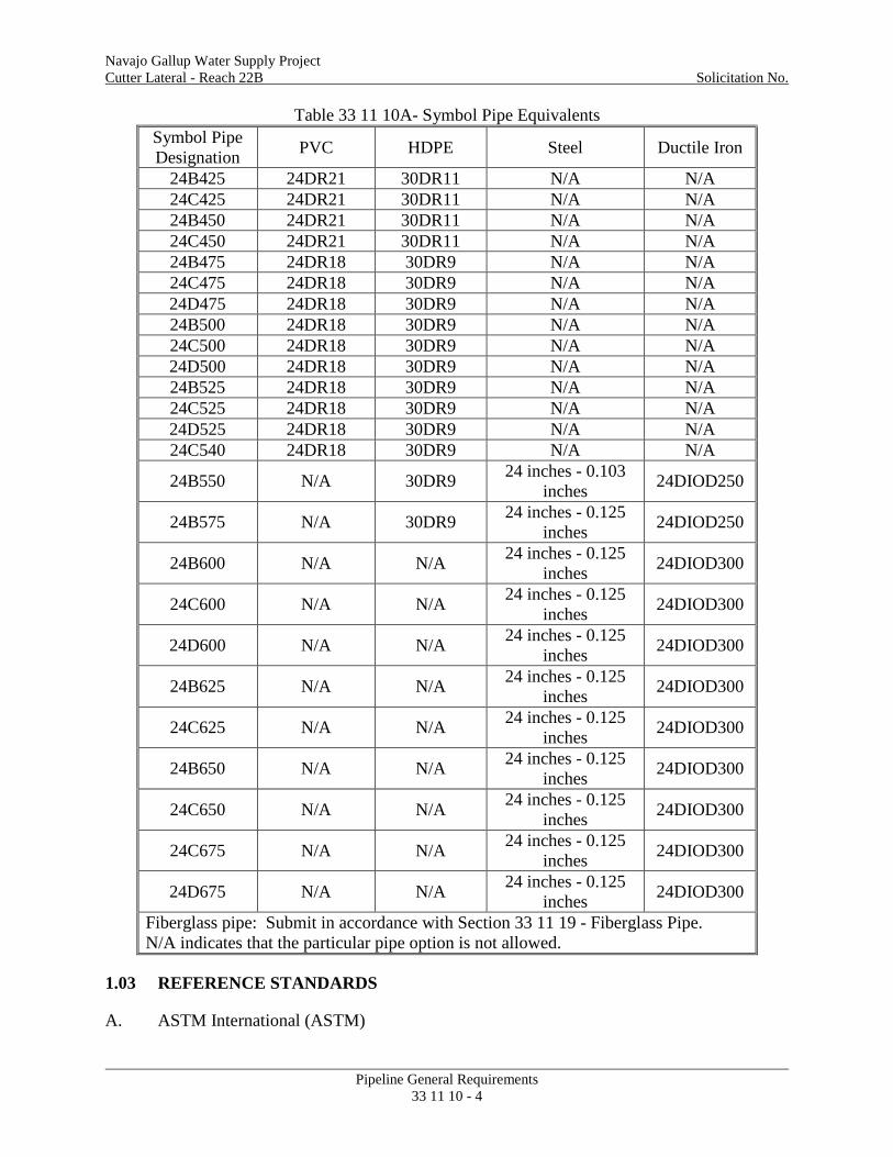
2. Symbol Pipe Designation is defined as follows:
1) First number in the symbol indicates nominal diameter in inches.
2) The alphabetic character represents the cover class of pipe where; A < 5 ft., 5 ft. < B < 10 ft, 10 ft. < C < 15 ft and 15 ft. < D < 20 ft.
3) Second number in the symbol is the hydrostatic head measured to centerline of pipe.
4) A symbol of 24C600 means the pipe is 24 inches in diameter with a cover between 10 and 15 feet and a hydrostatic head of 600 feet at the center line of pipe.
3. Unless specific reference is made to outside diameter of pipe, pipe diameters shown on drawings and used in this section are inside diameters.
4. Ductile Iron Pipe (DI):
a. Symbol identifies pipe as follows:
1) First number indicates nominal diameter in inches.
2) Nominal diameter nomenclature DIOD for ductile iron outside diameter.
3) The next number is the pipe pressure class in psi.
4) A symbol of 24DIOD250 means the nominal diameter of the pipe is 24 inches with a ductile iron outside diameter nomenclature. The pressure class is 250 psi.
5. Steel Pipe:
a. Symbol identifies the pipe as follows:
1) First number is the nominal diameter in inches.
2) The second number is the steel pipe wall thickness in inches.
3) A symbol of 24 inches - 0.125 inches means the nominal diameter for the pipe is 24 inches and the steel pipe wall thickness is 0.125 inches.
6. Pipe designations shown on drawings and in this section establish minimum requirements for pipe types allowed.
Table 33 11 10A- Symbol Pipe Equivalents
Symbol Pipe Designation PVC HDPE Steel Ductile Iron
2. ASTM F2164-13 Field Leak Testing of Polyethylene (PE) and Crosslinked Polyethylene (PEX) Pressure Piping Systems Using Hydrostatic Pressure
B. American Water Works Association (AWWA)
1. AWWA C205-12 Cement-Mortar Protective Lining and Coating for Steel Water Pipe - 4 in. (100 mm) and Larger - Shop Applied
2. AWWA C207-13 Steel Pipe Flanges for Waterworks Service Sizes 4 In. Through 144 in. (100 mm Through 3,600mm)
3. AWWA C600-10 Installation of Ductile Iron Water Mains and Their Appurtenances
4. AWWA C604-11 Installation of Steel Water Pipe 4 in. (100mm) and Larger
5. AWWA C605-13 Underground Installation of Polyvinyl Chloride (PVC) and Molecularly Oriented Polyvinyl Chloride (PVCO) Pressure Pipe and Fittings
6. AWWA C900-07 Polyvinyl Chloride (PVC) Pressure Pipe and Fabricated Fittings, 4 In. Through 12 In. (100 mm Through 300 mm), for Water Transmission and Distribution
7. AWWA C905-10 Polyvinyl Chloride (PVC) Pressure Pipe and Fabricated Fittings, 14 Inches through 48 Inches (350 mm Through 1,200 mm) for Water Transmission and Distribution
8. AWWA C906-15 Polyethylene (PE) Pressure Pipe and Fittings, 4 In. Through 65 In. (100 mm Through 1,650 mm), for Waterworks
C. International Organization for Standardization (ISO)
1. ISO 9001-15 Quality Management
D. National Sanitation Foundation (NSF)
1. NSF Standard 61-13 Drinking Water System Components - Health Effects
1.04 SUBMITTALS
A. Submit the following in accordance with Section 01 33 00 - Submittals:
B. RSN 33 11 10-1, Qualifications:
1. Resumes and references of line pipe manufacturers.
2. Pipe fuser certifications, if needed, for equipment to be used.
C. RSN 33 11 10-2, Pipelaying Diagrams:
1. For each type of pipe furnished.
2. Show position and marking of pipe sections.
3. Include centerline and invert stationing and elevations at horizontal and vertical changes in alignment, and subgrade elevation for each pipe fitting.
D. RSN 33 11 10-3, Filling and Testing Plan:
1. Proposed rate, time, and procedure for:
a. Cleaning.
b. Filling.
c. Field and pressure testing.
d. Draining pipeline.
2. Method of disposing of water drained from pipeline.
E. RSN 33 11 10-4, Floatation Prevention Plan:
1. Show location and describe method of preventing pipe from floating.
1.05 DELIVERY, STORAGE AND HANDLING
A. Place pipe in storage as directed by COR. Within 150 miles from site, as designated by COR.
1.06 REPAIR KIT
A. Furnish 1 repair kit for each type and size of pipe used.
2. At highest loading and pressure rating for each type of pipe used.
1.07 QUALIFICATIONS
A. Pipe manufacturer: 1. Certified in accordance with ISO 9001 or similar nationally certified quality
program as approved by COR. 2. At least 10 years of successful experience producing products as specified. 3. Provide references for at least 3 completed projects with proposed pipe products
between 18-inch and 36-inch diameter and pressure classes above 100 psi.
B. Welding procedures and welders in accordance with AWS D1.1 as applicable
C. Pipelaying Workers: Skilled and experienced in laying pipe with type of pipe and joint being furnished.
PART 2 PRODUCTS
2.01 PIPE CROSSINGS
A. See Section 33 11 50 - Pipe Crossings at Existing Utility Pipelines.
2.02 GENERAL
A. Confirm elevations and locations shown on drawings with COR prior to ordering pipeline materials.
2.03 PIPE OPTIONS
A. Listed in Table 33 11 10A-Symbol Pipe Equivalents and following sections:
1. 33 11 12 - Steel Line Pipe,
2. 33 11 13 - Ductile Iron Pipe,
3. 33 11 16 - PVC Pressure Pipe,
4. 33 11 18 - HDPE Pressure Pipe,
5. 33 11 19 - Fiberglass Pipe.
B. Materials and chemicals that may come into contact with drinking water certified by NSF 61.
A. Two Inch Diameter Air Valve Assemblies: See Section 33 12 10 - Valves and Equipment for Line Pipe Installations.
B. Four Inch Diameter Blowoff Assemblies: See Section 33 12 10 - Valves and Equipment for Line Pipe Installations.
PART 3 EXECUTION
3.01 GENERAL
A. Perform cleaning, filling and testing after backfill has been placed to finished grade or as approved by COR.
B. Surveyor licensed in the State of New Mexico shall be on site during excavation and pipelaying.
C. Protect pipe from contamination, damage, and the elements during storage on site by covering it with a tarp as directed by the COR.
3.02 INSTALLATION
A. Install pipe in accordance with appropriate Section for pipe option installed.
B. Lower pipe into the trench and place pipe in position such that no soil gets inside the pipe and pipe is not damaged.
C. Keep openings to installed pipe closed with watertight plugs during work stoppage, including end of work day, breaks, work delays.
D. After pipelaying and joining operations are completed, clean inside of pipe and remove debris. When pipelaying is not in progress, keep ends of pipelines closed.
E. If pipe is flooded during construction, clear floodwater by draining and flushing with water, or other approved method, until pipe is clean.
F. Lubricant:
1. Keep clean.
2. Apply with dedicated, clean applicator brushes.
G. Concrete in encasements, blocking and collars: Section 03 30 00 - Cast-in-Place Concrete.
1. Pipe joints to be fused or restrained from beginning to end of Wash Crossing stationing. See Section 35 42 35 - Bank Protection and drawings for locations.
3.03 FIELD EXAMINATION
A. Flush pipe before filling.
1. Flush foreign material from pipeline prior to testing.
2. Flush using a minimum velocity of 3 feet per second toward low points in reach.
3. Flush at least 3 pipe volumes until the water is clean as approved by COR.
4. Dispose of flush water in accordance with permits in Section 01 57 30 - Water Pollution Control.
5. Operate valves several times during flushing period.
3.04 FILLING PIPELINE
A. Provide water for filling and testing pipeline in accordance with Section 01 51 00 - Temporary Utilities.
B. Pipeline fill rate, maximum: 2 cubic feet per second.
C. Maintain pipeline completely filled for at least 72 hours before testing.
3.05 CONTRACTOR FIELD QUALITY TESTING
A. Leak testing pipeline:
1. Notify the COR at least 7 days before applying pressure to pipeline.
2. Do not start leak testing when snow or standing water is on the ground. Suspend testing as directed by the COR if precipitation accumulates on the ground.
3. Furnish pumps, power, pressure gages, air valves at each end of line and calibrated flow meters for testing.
4. Comply with applicable test standard except as noted below:
a. AWWA C605 for PVC.
b. ASTM F2164 for HDPE.
5. Test pipeline with hydrostatic pressure equal to:
a. 420 feet elevation downstream of Pre-manufactured Pump Station No. 1.
b. 460 feet elevation downstream of Pre-manufactured Pump Station No. 2.
6. Prior to starting test, maintain pressure in pipe for 24 hours.
7. Test for 96 hours or as approved by COR.
8. If leakage is detected, halt test. Identify and repair leaks.
7. AWWA C905-10 Polyvinyl Chloride (PVC) Pressure Pipe and Fabricated Fittings, 14 in. Through 48 in. (350 mm Through 1,200 mm), for Water Transmission and Distribution
1.03 SUBMITTALS
A. Submit the following in accordance with Section 01 33 00 - Submittals.
B. RSN 33 11 16-1, Shop Drawings:
1. Show fitting fabrication details. Include: miter bend fabrication details (angles, leg lengths), restrained lengths, inside pipe diameters.
2. Dimensions of joints, diameter of rubber gasket including tolerances, other major dimensions, proposed restraint, and location which include station and elevation.
3. Connections details to other pipe types.
C. RSN 33 11 16-2, Pipe Manufacture Certification:
1. Pipe and miter bends meet AWWA C905.
2. Saddle and Sleeve product data.
D. RSN 33 11 16-3, Test Results:
1. Manufacturer’s steel fitting test results.
1.04 QUALIFICATIONS
A. See 33 11 10 - Pipeline General Requirements.
1.05 DELIVERY, STORAGE, AND HANDLING
A. Ship pipe after receiving COR approval of pipe manufacture per submittal.
B. Prevent damage to PVC pipe and fittings during loading, transporting, unloading, storing, and laying.
C. Transport coated fittings with padded bolsters between the pipes. Use heavy padding under ties.
D. Provide sun protection for PVC pipe that is stored outside.
1. At a minimum, wrap pipe in an adequately fastened opaque covering.
a. In warm climates, allow air circulation through and around the pipe by puncturing or cutting the covering in the area of the pipe ends.
E. Support and store pipe above ground surface. Do not allow bells and spigots to contact each other or the ground.
3. Make other changes in alignment and grade by providing deflections at joints.
a. Maximum deflection: 1 degree or deflection recommended by pipe manufacturer, whichever is less.
4. Longitudinal bending of pipe to obtain deflection: Not permitted.
5. Other methods of providing curves in pipelines may be submitted; and if approved, use these methods to install curves at no additional cost to the Government.
a. Methods of providing curves in pipelines which incorporate rubber gasket joints encased in concrete will not be approved.
G. Connections Between PVC Pressure Pipe and Other Types of Pipe:
1. Use rubber gasketed mechanical joints to make connections between PVC pressure pipe and other types of pipe.
H. Schedule work so that at no time will pipe remain in the trench more than 7 days before backfill is placed to original ground surface or to other specified backfill limits shown on drawings.
I. Thrust Restraint:
1. Joint restraint products or other restraint method at miter bends as shown on drawing 1695-D-60049.
a. Other methods of restraint may be used as approved by COR.
b. Coat in accordance with Section 09 96 20 - Coatings.
J. Backfill pipe in accordance with Section 31 23 22 - Pipe Trench Earthwork.
1. Place backfill about pipe carefully to avoid lateral displacement of the pipe and damage to joints.
2. In certain pipeline reaches, where determined necessary by the COR to prevent the possibility of flotation, do not lay more than 300 linear feet of pipe ahead of backfilling operations.
3. If pipelaying operations are interrupted for more than 24 hours, cover pipe laid in the trench with backfill.
3.02 TOLERANCES
A. Lay pipe to lines and grades shown on drawings or established by the COR to the following tolerances:
1. Departure from and return to established alignment and grade, maximum: 1/16 inch per foot of pipe.
2. Total departure from established alignment and grade, maximum: 1 inch.
3.03 PIPE DEFLECTION
A. Allowable vertical pipe diameter deflection after backfilling is complete:
1. Decrease, maximum: 5 percent of nominal pipe diameter.
2. Elongation, maximum: 3 percent of nominal pipe diameter.
B. Within 2 weeks after backfilling is completed, take measurements of internal diameters.
1. Certified by machine manufacturer or representative.
2. Trained on specific fusion machine and bonding procedure and shall:
a. Perform 1 pipe-to-pipe bond and,
b. One pipe-to-fitting bond on each machine to be used.
c. Bonds made as part of operator certification shall be:
1) Visually inspected and tested in accordance with PPI and ASTM standards.
3. Qualification remain in effect for 6 months from date of qualification.
a. Ability to be revoked by certifying entity.
1.05 DELIVERY, STORAGE, AND HANDLING
A. Prevent damage to pipe and fittings during loading, transporting, unloading, storing, and laying.
B. Transport pipe and fittings with padded bolsters. Use heavy padding under ties.
C. Support and store pipe above ground surface.
PART 2 PRODUCTS
2.01 PIPE
A. HDPE Pressure Pipe: AWWA C906, except;
1. PE material:
a. Standard PE code designation: PE 4710.
b. Minimum cell Classification, ASTM D3350: PE 445574C, or E.
2. Each production lot of pipe shall be tested for melt index, density, percent carbon, dimensions and ring tensile strength.
3. Approved for potable water in accordance with NSF Standard 61.
4. Not less than 4 permanent co-extruded, equally spaced, blue color stripes in outside surface of pipe.
2.02 FITTINGS
A. Adaptors, couplings, bends, and connections at structures and encasements: Fabricated from HDPE unless otherwise specified, or as shown on drawings.
1. Material: Ductile iron, Class 150, ASME B16.1 or ASME B16.5, coat in accordance with Section 09 96 02 - Coatings.
C. Steel Fittings:
1. Steel for Fittings: ASTM A283, grade C or D; or ASTM A36.
2. Minimum Steel Wall Thickness: 10 gauge or greater.
3. Welding:
a. AWS D1.1.
b. Temporary or permanent welding for convenience of Contractor: Not permitted on areas where welding will damage fusion-epoxy lining and coating.
c. Lifting eyes and other handling devices: Made part of fitting before lining and coating are applied.
4. Coatings and Linings:
a. Fusion epoxy or coal-tar epoxy paint in accordance with Section 09 96 02 - Coatings.
D. HDPE Pipe Fittings:
1. Molded fittings constructed of HDPE PE 4710 in accordance with ASTM F714 and ASTM F2206.
2. Made by heat fusion joining specially machined shapes cut from pipe, polyethylene sheet stock or molded fittings;
a. Rated for internal pressure service at least equal to full service pressure rating of mating pipe.
b. Tested in accordance with AWWA C906.
3. HDPE flange and mechanical joint adaptors shall be rated to at least the same pressure as mating pipe.
4. Polyethylene flange or mechanical joint adapters made with sufficient through-bore to be clamped in a butt fusion-joining machine without use of a stub-end holder, as per pipe manufacturer’s instructions.
5. HDPE fabricated mechanical adapters shall have steel stiffeners.
2.03 CONCRETE
A. Concrete in encasements, blocking and collars: Section 03 30 00 - Cast-in-Place Concrete.
1. General: AWWA C906 testing of HDPE pipe and fittings and ASTM F2634 testing of HDPE factory test fusions.
a. Completed and documented by qualified personnel.
b. Government reserves right to:
1) Observe testing while in process and to receive testing documentation.
2) Inspect materials both during and after manufacture.
c. Testing reports shall have unique identifiers with shipping bills to verify that pieces shipped belong to same as those tested.
2. Test in accordance with AWWA C906 and/or ASTM F714.
a. Perform 1 butt fusion in accordance with ASTM F2620 and PPI Technical Report TR-33 on each run of pipe and from each batch of material feedstock.
1) Test using Tensile Impact Test in accordance with ASTM F2634 prior to shipping pipe.
b. Joints exhibiting yield point lower than unfused pipe or that fails in a brittle mode is considered unacceptable.
c. Unacceptable test result, Government may reject pipe manufactured in same run and from same batch of material feedstock represented by unacceptable test. Manufacturer may, at own expense, supply additional testing to COR.
d. Acceptable test results do not:
1) Mean that pipe from pipe run or material feedstock batch will be acceptable.
2) Relieve pipe manufacturer or supplier from liability for defects in material or workmanship of pipe discovered during installation or warrantee period.
3. HDPE pipe out-of-roundness tolerances shall not exceed maximum allowances in ASTM D2513, Table 2.
a. HDPE pipe ovality: plus or minus 3 percent at pipe manufacturing facility.
B. HDPE Fittings:
1. Each fitting to be five-second pressured tested in accordance with AWWA C906.
c. Supply data on fusion joints upon request of COR.
7. Thermal Contraction and Expansion of HDPE Pipe:
a. COR may unbolt flange at transition between HDPE and steel to check for tensile or compressive loading due to thermal contraction of the HDPE pipe.
b. Excessive tension or excessive compression of flange shall be cause for Contractor to excavate HDPE pipe, lengthen or shorten and re-bury at own cost.
C. Changes in Alignment and Grade:
1. Where shown as miter bends on drawings, make changes in alignment and grade with miter bends or submit proposal to COR for approval.
2. Make other changes in alignment and grade by bending pipe.
a. Minimum cold (field) bend radius shown in Table 33 11 18A - Minimum Cold Bending Radius.
Table 33 11 18A - Minimum Cold Bending Radius
Pipe DR Minimum Cold Bending Radius
≤ 9 20 times pipe OD
>9 to 13.5 25 times pipe OD
>13.5 to 21 27 times Pipe OD
>21 30 times pipe OD
Fitting or flange present or to be installed in bend
100 times pipe OD
D. After pipelaying and joining operations are completed, clean inside of pipe and remove debris. When pipelaying is not in progress, keep ends of pipelines closed.
E. Closure sections:
1. Last fusion joint for HDPE pipe to HDPE pipe closure sections:
F. Pipe will remain in the trench no more than 7 days before backfill is placed to original ground surface or to other specified backfill limits shown on drawings.
G. Backfill pipe in accordance with Section 31 23 22 - Pipe Trench Earthwork.
3.02 TOLERANCES
A. Lay pipe to lines and grades shown on drawings or established by the COR to the following tolerances:
1. Departure from and return to established alignment and grade, maximum: 1/16 inch per foot of pipe.
2. Total departure from established alignment and grade, maximum: 1 inch.
3.03 CONTRACTOR FIELD QUALITY TESTING
A. Fusion Quality Testing on Polyethylene pipe:
1. Frequency:
a. Minimum: 1 per crew per week or at request of COR.
b. Maximum: 10 percent of welds.
c. Additional testing may be required during changes in:
1) Weather.
2) Fusion machine.
3) Fusion crew.
2. Procedure:
a. Cool trial fusion, then.
1) Cut out test coupons.
2) Test using Tensile Impact Method accordance with ASTM F2634.
3. Rejection of Fusion Joints:
a. Exhibits a yield point lower than unfused pipe or,
b. Fails in brittle mode.
c. Field fusions represented by trial fusion shall be rejected.
1) Make corrections at Contractor expense and re-make rejected fusions.
B. Test field welds on steel pipe and fittings using ultrasonic or radiographic method in accordance with AWS D1.1.
C. Transport pipe and fittings on padded bolsters either curved to fit the outside of the pipe or using triangular chocks. Use heavy padding under ties.
D. Support and store pipe above ground surface. Do not allow bells, couplings or spigots to contact each other or the ground.
E. Use manufacturer’s instructions for handling of pipe.
F. Replace or repair, as approved by the COR, pipe that is damaged during shipment, storage, or installation at the Contractor’s expense.
PART 2 PRODUCTS
2.01 PIPE
A. Fiberglass Pipe: In accordance with AWWA C950 and ASTM D3517.
1. Pressure pipe utilizing a continuous filament wound process with: a. Type 1: glass fiber-reinforced thermosetting polyester resin mortar.
b. Liner 1: reinforced thermoset liner.
c. Grade 1: polyester resin surface layer - reinforced.
d. Class: see Table 33 11 10A - Symbol Pipe Equivalents for required line pipe sizes and pressure classes.
e. Pipe Stiffness: 18 psi minimum.
B. Design pipe for the maximum sustained working pressure and the surge pressure.
1. The maximum sustained and surge pressures are considered the same and are defined by the head classes shown on pipeline plan and profile drawings.
C. Elastomeric Sealing Gaskets: Manufactured and tested in accordance with ASTM F477.
2.02 FITTINGS
A. Tees, bends, adapters, and connections at structures and encasements:
1. As shown on drawings. 2. Fittings should resist the same loading conditions as the adjacent pipe.
B. Fittings: Fabricated from fiberglass, steel or ductile iron.
1. Fiberglass Fittings: In accordance with AWWA M45, AWWA C950, and ASTM D3517.
a. Installed in accordance with manufacture’s recommendations.
1. Test in accordance with AWWA C110 or AWWA C153.
PART 3 EXECUTION
3.01 LAYING PIPE
A. Excavate pipe trench in accordance with Section 31 23 22 - Pipe Trench Earthwork.
1. Grade pipe trenches to provide uniform slope along bottom of pipe.
2. At joints involving bells or collars, provide holes at joint of ample size to prevent bells or collars from coming in contact with subgrade.
B. Keep pipe trenches free of water during pipelaying operations.
C. Lower pipe into the trench and place pipe in position such that no soil gets inside the pipe and pipe is not damaged.
D. On grades exceeding 10 percent, lay pipe uphill.
E. When pipelaying is not in progress, keep ends of pipelines closed.
F. Joining Pipe:
1. Follow manufacturer’s recommendations for installation.
2. Inspect pipe end and/or coupling, elastomeric gasket, and sealing surfaces for damage.
3. Before assembling pipe joints, clean gasket, bell or coupling, especially the groove, and the spigot with a rag, brush, or paper towel to remove dirt or foreign material.
4. Placing Elastomeric Gasket:
a. Spigot Groove Method:
1) Follow manufacturer’s recommended practices for gasket installation.
2) Apply manufacturer’s approved joint lubricant to spigot interior and elastomeric gasket.
3) After placing elastomeric gasket in spigot groove, equalize elastomeric gasket cross section by inserting a tool such as a large screwdriver under the elastomeric gasket and moving it around the periphery of the pipe spigot.
b. Coupling Groove Method:
1) Follow manufacturer’s recommended practices for gasket installation. Typically this method is factory installed.
5. Fit pipe units together, spigot to bell or coupling, and draw the joints together so that the bells or couplings and spigots are fully engaged.
6. Do not swing or "stab" the joint and do not suspend the pipe and swing it into the bell or coupling.
7. Fit pipe units together in a manner to avoid twisting or otherwise displacing or damaging the elastomeric gasket.
8. When using gaskets of circular cross section, after pipe units have been joined, insert a feeler gauge between the pipe bell and pipe spigot and move it around the periphery of the pipe to determine that the position of the elastomeric gasket is correct and there are no fish-mouth problems. If adjustment of the position of a length of pipe is required after installation, remove and relay the length of pipe as for a new pipe.
9. Maintain pipe securely in final position.
G. Changes in Alignment and Grade:
1. Make changes in alignment and grade with miter bends.
2. Make minor changes in alignment and grade by pulling pipe joints.
a. Pull rubber gasket coupling or bell and spigot joint.
b. Maximum deflection:
1) 1 degree or deflection As recommended by pipe manufacturer, whichever is less for pipe head class less than or equal to 450 feet.
2) 0.75 degree or deflection recommended by pipe manufacturer, whichever is less for pipe head class equal to or greater than 475 feet.
3. Lay ends of each section of pipe on the theoretical centerline of the curve and to the grade shown on the drawings within the laying tolerances prescribed above.
H. Thrust Restraint:
1. Restrained joint couplings in combination with concrete blocking, encasements and collars.
a. Concrete in encasements, blocking and collars in accordance with Section 03 33 00 - Cast-in-Place Concrete.
2. Joint restraint couplings to lengths shown on drawing 1695-D-60049:
a. Double bell with rubber gaskets and locking rods.
3. Alternate methods of coupling restraint may be used if approved by the COR.
I. Closure Sections:
1. Use closure sections where necessary as determined by the Contractor, subject to the approval of the COR.
J. After pipelaying and joining operations are completed, clean inside of pipe and remove debris. When pipelaying is not in progress, keep ends of pipelines closed.
3.02 TOLERANCES
A. Lay pipe to lines and grades shown on the drawings or established by the COR to the following tolerances:
1. Total departure from established alignment and grade, maximum: 1 inch.
3.03 BACKFILL
A. Backfill pipe in accordance with Section 31 23 22 - Pipe Trench Earthwork.
1. Place backfill about pipe carefully to avoid lateral displacement of the pipe and damage to joints.
2. In certain pipeline reaches, where determined necessary by the COR to prevent the possibility of flotation, do not lay more than 300 linear feet of pipe ahead of backfilling operations.
3. If pipelaying operations are interrupted for more than 24 hours, cover pipe laid in the trench with backfill.
3.04 PIPE DEFLECTION
A. Allowable vertical pipe diameter deflection after backfilling is complete.
1. Decrease, maximum: 3 percent of nominal pipe diameter.
2. Elongation, maximum: 1.5 percent of nominal pipe diameter as measured when backfill reaches pipe crown.
B. Within 2 weeks after backfilling is completed, take measurements of internal diameters.
C. Measurement Frequency:
1. Midpoint of pipe section at approximate 50 feet intervals for the first 500 feet of backfilled pipe, and once every 200 feet intervals thereafter.
2. In areas of deep burial or where special problems are encountered, the frequency of measurements may be increased at the discretion of COR.
D. Measurements:
1. Measure vertical and horizontal diameter at approximate midpoint of pipe unit.
2. Record pipe deflections and station where measurements were taken.
3. If a pipe deflection exceeds the allowable:
a. Take measurements at midpoint of pipe unit upstream and downstream at approximate 50 foot intervals to determine extend of excessive deflection.