25
NHDES Guidance for the Energy Efficient Design of Drinking Water System Infrastructure

NHDES Guidance for the Energy Efficient
Design of Drinking Water System
Infrastructure

2
WD-20-03
NHDES Guidance for the Energy Efficient Design of
Drinking Water System Infrastructure
Prepared by the
New Hampshire Department of Environmental Services
Drinking Water and Groundwater Division
29 Hazen Drive Concord, NH 03302-0095
September 2020
Robert R. Scott, NHDES Commissioner
Thomas O’Donovan, Director of NHDES’ Water Division

3
Acknowledgments
The New Hampshire Drinking Water System Energy Efficiency Design Supplement (EE Design Supplement)
was developed to provide energy efficiency design strategies that can be promoted by the New Hampshire
Department of Environmental Services (NHDES). The document is intended to be used as guidance to
improve the energy efficient design of water system pumping stations, infrastructure and water treatment
facility upgrades. In addition to the specific recommendations provided in this document, the benefits of
performing a comprehensive process energy evaluation and meeting with electric utility representatives
before starting a design project can help identify additional energy saving projects that can be included in
the project scope that may qualify for NHSaves incentives which may make the projects more financially
feasible and appealing to the communities.
Steve Bolles, Process Energy Services
Mark Toussaint, Eversource
Bob Reals, Liberty Utilities
Bob Reals, New Hampshire Electric Cooperative
Sharon Nall, NHDES
Sarah Pillsbury, NHDES
4
Table of Contents 1.0 Energy Efficiency Perspective _______________________________________________ 6
2.0 Efficient Infrastructure Design ______________________________________________ 7
2.1 Raw Water Reservoirs ________________________________________________ 7
2.2 Finished Water Tanks _________________________________________________ 8
2.3 Finished Water Piping & Pressure Loss ___________________________________ 8
2.4 PRVs/System Pressure Controls ________________________________________ 9
3.0 General Process Equipment & Control System Design ____________________________ 9
3.1 Pump Systems ______________________________________________________ 9
3.2 Blowers & Mixers ___________________________________________________ 10
3.3 Motors and VFDs ___________________________________________________ 10
3.4 SCADA & Control Systems ____________________________________________ 11
3.5 Electric Submeters __________________________________________________ 11
4.0 Groundwater Systems ____________________________________________________ 12
4.1 Wells _____________________________________________________________ 12
4.2 Air Strippers & Chemical Treatment ____________________________________ 13
5.0 Water Treatment Plants & Distribution ______________________________________ 13
5.1 Raw Water Pumping ________________________________________________ 13
5.2 Flocculation/Sedimentation __________________________________________ 13
5.3 Filtration __________________________________________________________ 14
5.4 Chemical Systems ___________________________________________________ 14
5.5 Sludge Handling ____________________________________________________ 14
5.6 Finished Water Pumping _____________________________________________ 14
5.7 Booster Pumping ___________________________________________________ 15
6.0 Building Construction & Equipment System Design _____________________________ 15
6.1 Building Construction________________________________________________ 15
6.2 Building System Equipment ___________________________________________ 16
6.2.1 Lighting ___________________________________________________________ 16
6.2.2 Heating & Ventilation Systems ________________________________________ 16
5
6.2.3 Dehumidification ___________________________________________________ 17
6.2.4 Domestic Hot Water ________________________________________________ 18
6.3 Emergency Generators ______________________________________________ 18
7.0 Renewable Energy _______________________________________________________ 18
7.1 Net Metering ______________________________________________________ 18
7.2 PV Solar Systems ___________________________________________________ 19
7.3 Transpired Solar Wall Collectors _______________________________________ 19
7.4 Wind Turbines _____________________________________________________ 19
7.5 Hydro Turbines _____________________________________________________ 19
8.0 Utility Rate Schedules & Fuel Costs__________________________________________ 20
8.1 Electric Utility Rate Schedules __________________________________________ 20
8.1.1 Demand Charges ___________________________________________________ 20
8.1.2 Power Factor Correction _____________________________________________ 20
8.1.3 Off-Peak Rates _____________________________________________________ 21
8.2 Fuel Source for Space Heating & Emergency Generators ____________________ 21
9.0 Documentation _________________________________________________________ 22
9.1 O&M Manual ______________________________________________________ 22
9.2 Benchmarking _____________________________________________________ 22
9.3 Non-Revenue Water ________________________________________________ 23
10.0 Energy Guidance Document Implementation _________________________________ 23
10.1 Energy Guideline to Evaluate Project Cost Effectiveness ____________________ 24
10.2 Initiatives to Develop Energy Efficiency Projects __________________________ 24

6
1.0 Energy Efficiency Perspective
The concept of being more efficient is commonly applied to all aspects of facility operations. The term may
be loosely used without specific calculations that quantify real cost savings. For energy related
improvements, the majority of efficiency projects are focused on equipment component “efficiency”
upgrades (motors, pumps, HVAC equipment) or building construction/equipment improvements. Facilities
are also influenced when electric utilities provide prescriptive financial incentives for component efficiency
improvements (motors, lights, HVAC equipment) instead of looking at the entire system efficiency.
Very rarely is a broader perspective applied to quantify the long-term benefits of reducing non-revenue
water or the potential cost reduction and related energy savings for avoiding or downsizing facility
upgrades. These higher-level reviews may also quantify environmental benefits (such as the carbon
footprint) and the energy/material production that goes into the entire construction process. This type of
perspective embraces the idea that “the most efficient facility is the one that is never built” and the
importance of reducing water distribution system leakage and pursuing water conservation opportunities
before expensive facility upgrades are considered.
The NHDES 2020 theme of “Data to Dollars” (originally used for the NHDES
Asset Management Program) illustrates how data collection can be reviewed
and connected with meaningful costs to better define the real “bottom line”
savings of energy efficiency projects. Again, this is about quantifying the
costs/benefits of projects – not just buying a new motor, VFD or pump
because a vendor indicated that it would be “more efficient” or that the
electric utility would provide an incentive.
For water and wastewater systems, this can be illustrated with the decision-making process when building
a simple pump station. If reducing carbon footprint is the primary concern, then each design decision
should include research further back into the production of materials/construction methods to evaluate
the environmental impact. For example, it is difficult to say that heat pumps have a lower carbon footprint
than natural gas heaters unless the power supply generation mix in New England is considered.
According to the ISO New England website, 78% of power was generated from natural gas and nuclear in
2019. The efficiency converting natural gas to electric power (~38%) and transmission/line losses (5%
estimated from Energy Information Administration at EIA.gov) should also be included. These details are
essential if the carbon footprint is the key factor in the decision making process.
Ultimately, the core benefit of efficiency projects that carries the greatest weight with stakeholders is
energy cost savings. This also is the one part of the project that can be quantified with a reasonable
amount of effort, and when paired with a preliminary cost estimate, provides the simple payback
relationship that all parties recognize to provide accountability. Due to the reality of time/budget
constraints and the accuracy of analyzing the benefits beyond this level, the opportunity to reduce a
facility’s carbon footprint should be accepted as a side benefit since highlighting this factor to justify
taxpayer/customer dollars is often not enough to persuade decision makers to move forward with a
project.

7
Each of the decisions made throughout the design process impacts construction costs, lifetime energy costs
and carbon footprint. These concepts have been applied to the pump station construction example below.
Compare long-term benefits of alternative options before moving forward with the pump station
construction.
Evaluate the benefits of reducing station building size and the potential for using submersible or
below grade pumps to reduce building materials and long term heating costs.
Determine if a permanent generator is required (20+ years of operating a 1500-watt block heater
at 120+ degrees) or can a portable generator (typically no block heater) be used for multiple sites.
Evaluate the environmental impact of the size of the building. Should the additional cost of LEED
certification be pursued to certify that the building is more “efficient”? Should the building wall
construction be increased to accommodate more insulation? Should solar panels be considered
even though the simple payback may be 15+ years?
Should stand-alone cost effectiveness be used to evaluate the economic benefits of projects or
should incentive money be included in the analysis?
What is the best choice for the pump station heating system? If it’s judged based on component
efficiency, a heat pump would most likely be the choice. If it’s based on smart engineering and cost
effectiveness, a small panel heater in the control panel and heat tape around the piping may be the
most cost effective solution and offer the greatest “system efficiency.”
Minimizing infiltration and maintaining pump station thermostat settings as low as possible are the
most cost effective actions that every system operator can do to maintain low energy use and
reduce the building carbon footprint. This action typically provides a greater environmental impact
than covering the pump station roof with solar panels or investing in “high efficiency” equipment.
The selection of a tankless, on demand hot water heater to provide tempered water to an
emergency shower station should be considered instead of a standard hot water tank. This will cost
more up front but will reduce energy use over the life of the equipment.
This document has been developed to encourage engineers to use their skills to step back from the design
process and evaluate system efficiency with a different perspective that incorporates cost effective
efficiency improvements into every part of a project.
On a smaller scale but perhaps just as important message from this guideline is the role that water system
owners and operators play in creating more energy efficient water systems.
2.0 Efficient Infrastructure Design
2.1 Raw Water Reservoirs
No energy efficiency recommendations at this time

8
2.2 Finished Water Tanks
The effective use of water storage in the system is based on a number
of factors including fire flow, adequate pressure for high elevation
services, and sufficient turnover for water quality. Water storage
capacity can also provide municipalities with the option of taking
advantage of off-peak energy rates. Having adequate storage to
consistently allow distribution system pumps to only be activated
during the off-peak evening hours can provide long-term energy
savings for municipalities. In some cases, tank capacity is excessive, and
maintaining a lower elevation can be done without compromising fire
flow capacity or system pressure.
The energy savings for operating large pump systems off-peak can be
significant enough to justify additional instrumentation and improved
controls, but typically cannot support the expense of additional tanks.
The Antrim/Bennington Water System is currently considering this
strategy to operate their well pumps off-peak. The cost for tank SCADA improvements was determined to
be approximately $11,500 (for two tanks) to activate the wells off-peak with the tank levels used as a
secondary method of control. With annual energy cost savings of $6,600, the cost of the control system
upgrade will pay for itself in less than two years.
If the tanks are not large enough to take advantage of off-peak electric rates, maintaining the lowest
elevation possible without compromising water quality or fire flow reduces the head or pressure on all
parts of the distribution system. The slightly lower system pressure typically reduces system leakage and
the lower average static head (elevation between pump suction and discharge tank level), reduces pumping
energy use.
2.3 Finished Water Piping & Pressure Loss
Distribution system frictional losses can be challenging to reduce cost effectively when older distribution
lines have tuberculation/sediment buildup? within the piping over many years of service.
Repairing/replacing large sections of distribution piping to reduce friction losses are typically not cost
effective based only on pump system energy savings. Pipeline cleaning projects have included “jet
cleaning” and “pipeline pigging” which uses foam bullet shaped inserts with pressurized water to scour the
piping. These methods can increase flow and reduce system pumping energy use enough to make these
projects cost effective and extend the life span of the distribution piping.
Higher or lower friction losses can be a problem when head calculations for pump systems are not
accurate. During start-up/commissioning, engineers have resorted to throttling the pump discharge valve
for oversized/mismatched pumps to avoid “running out on the head curve” which can result in high
amperage draw, premature pump wear and cavitation. For these situations, it is typically more cost
Water-Storage-Tank-Peterborough-NH

9
effective to downsize the pump with a smaller impeller, install a variable frequency drive (VFD) or even
replace the pump unit if the pump run time is high enough
Pump station friction losses within a pump station can be minimized with low-friction loss component
selection (check valves, surge relief valves, etc…). For example, selecting a ball type pressure/surge relief
valve instead of a globe type valve can reduce system discharge pressure by 2 to 4 psi, which can result in
thousands of dollars in pump system energy savings over the life of the equipment.
Some municipalities have installed strainers before turbine type meters as a low capital cost option.
However, as the strainers become clogged and create higher head losses, the initial selection of the low
cost turbine meter results in higher energy costs (pump shaft horsepower = flow * head / 3960 / pump
efficiency) compared to investing in a magnetic type flow meter with lower head and a corresponding
lower power draw.
2.4 PRVs/System Pressure Controls
A pressure-reducing valve (PRV) typically requires an on-site building for the piping and controls. A small
electric heater and dehumidifier are used to prevent excessive condensation and provide freeze protection.
For systems with consistent flow and adequate pressure drop, a PRV station can also provide the
opportunity for installing a hydroturbine unit (also discussed in Section 7.5).
3.0 General Process Equipment & Control System Design
3.1 Pump Systems
Water system pump equipment typically represents over 80% of water system energy use. In addition to
selecting a suitable pump that matches the required flow and head requirements, engineers should also
include design features and instrumentation that give operators the ability to optimize pump system
operation.
Water system pump types include vertical turbine and submersible pumps for groundwater wells, and
horizontal split case, end suction or vertical multi stage centrifugal pumps for raw water/finished water and
booster pump systems. Semi open and closed type impellers are often used for water system centrifugal
pumps to achieve high efficiency.
Designing and operating a pump system efficiently requires key field data to evaluate pump system
performance and an awareness of utility rate schedules to develop an operating strategy that provides the
lowest energy cost. Although flow meters are included for the majority of pump systems, well level
transducers, kW submeters (or VFDs with a kW display) and reliable discharge pressure instrumentation are
also needed to give operators enough field data to evaluate pump system efficiency on a regular basis. For
pump upgrades, a system curve should also be developed from field pressure measurements to size the
pump based on actual system conditions.

10
In January 2020, the US Department of Energy (DOE) energy efficiency standard 10CFR 431.462 for clean
water pump systems went into effect. The standard applies to all manufactured clean water pumps
between 1 and 200 hp with a nominal speed of 1800 or 3600 RPM and a flow that exceeds 25 gpm at full
speed operation.
The standard provides a pump energy index (PEI) metric for common types of centrifugal pumps. The
metrics also consider whether the pump application is a constant or variable load system. A PEI greater
than 1.0 indicates that the pump consumes more energy than allowed by the DOE standard, and a rating
below 1.0 indicates compliance. Engineers and Owners should work with manufacturers when specifying a
pump to determine if a proposed pump complies with the DOE Standards. Even though some submersible
pumps are excluded from the standards, a pump/motor efficiency comparison can still be done to
determine the impact on long-term energy costs for each application. A general description of the energy
efficiency standards.
3.2 Blowers & Mixers
Blowers and mixers should be sized to operate at the highest efficiency for average flow conditions when
possible. If Variable Frequency Drives (VFD) are applied, the most efficient speed and recommended
operating range should be included in the specifications.
Passive chemical mixing can be accomplished with the use of static mixers. If a mechanical mixer is required,
it should include a VFD to allow the operator to manually adjust mixer capacity to the minimum level needed
for suitable mixing.
3.3 Motors and VFDs
Specifying premium efficiency motors that comply with National Electrical Manufacturers Association
(NEMA) efficiency standards has become a common design practice for new centrifugal pump systems.
However, submersible pump motors are exempt from these standards, and although premium efficiency
motors are an option from some submersible pump manufacturers, the additional savings versus cost
should be evaluated. This analysis should include the annual kW demand savings (based on the higher
efficiency) and kWh savings determined using the estimated pump run time.
When pumps are equipped with VFDs, they should be selected to have the best efficiency point at a value
close to the expected average flow instead of selecting the pump with a best efficiency point at the
maximum flow point. An alternative is to include space for a smaller “pony” pump that operates at a lower
capacity for low flow requirements and larger pumps for high flow conditions. The additional cost for a
pony pump or VFD should be evaluated for each pump application.
VFDs should only be proposed if the system frictional head is high enough to provide energy savings by
operating at reduced speeds, when excessive pump cycling could occur, or if demand savings can be
realized by programming the VFDs to operate at lower speeds until future higher flows are required. VFDs
should not be specified without energy saving calculations to justify the additional expense. Including a VFD
to only provide equipment with soft start capability introduces an additional component that reduces

11
system reliability and creates a 3% system loss compared to a lower cost soft start motor starter with less
than 1% efficiency loss.
For small booster pump stations (less than 10 hp), VFDs do not typically provide a significant energy saving
benefit compared to using a hydro pneumatic tank. However, for large pump systems with higher flows,
VFDs may provide the benefit of less pump cycling, and lower energy costs.
3.4 SCADA & Control Systems
The majority of water systems are equipped with basic Supervisory Control And Data Acquisition (SCADA)
systems that are primarily used to display run time/flow/process data (visually on a system schematic
screen). Additional screens summarize equipment run time and can provide graphs of the process data
over a selected interval (day/week/month). Features that are typically not included, but would help
quantify system performance and potentially identify efficiency improvements include:
The ability to display an average of a selected process interval for trended data. This provision
should be configured to exclude inactive equipment operation data.
A screen that displays equipment run time is a standard feature for most facilities. However, the
run time display is typically a cumulative value from when the system was initially installed. Having
an interval run time (such as a reset column next to a cumulative column) could be included as part
of a SCADA system design at a minimal cost.
Installing temperature/humidity sensors integrated with SCADA systems has been used successfully
by many New Hampshire municipalities to remotely monitor pump station temperatures to
minimize space heating costs.
3.5 Electric Submeters
It is becoming more common to install electric submeters for multiple sub
panels or high-energy systems with the intention of providing useful energy
use data. Unfortunately, these meters are not used due to complicated
menus and minimal training during project commissioning. Improving
facility staff training and providing sample templates on how the data could
be used would help staff evaluate system efficiency on a regular basis.
To make better use of submeters, the following is recommended:
Install kWh/kW meters for each major process and each motor control center. For example,
monitoring energy use specifically for the finished water pump system will allow facility staff to
evaluate energy use compared to total flow pumped. If energy use increases, it will help identify if
pump efficiency has decreased, or if controls need to be adjusted to optimize pump/VFD
operation. The key factor is to be able to assess system efficiency by benchmarking energy use
with a process variable.

12
Specify simple meters that provide instantaneous kW and cumulative kWh. Having the ability to
activate and deactivate demand/energy use data collection for trending is also a useful feature.
This energy data can also be transmitted to the plant SCADA system.
As part of the facility O&M manual/SOPs, include an example of how the energy use data can be
recorded and used to evaluate system efficiency.
Energy submeters (specifically for system equipment), pressure taps/gauges and flow meters will provide
the information needed for staff to evaluate system efficiency. The pressure transducers can also transmit
the data to the plant SCADA system to provide continuous trending/monitoring.
4.0 Groundwater Systems
4.1 Wells
Designing and operating a well pump system efficiently
requires key field data to evaluate pump system
performance and an awareness of utility rate schedules to
develop an operating strategy that provides the lowest
energy cost. Although flow meters are included for the
majority of wells, well level transducers, kW submeters and
reliable discharge pressure instrumentation should be
included in the well pump system design. This data will give
operators the information needed to evaluate pump system
efficiency on a regular basis.
Many designers/municipalities have been replacing traditional vertical turbine type pump systems with
submersible pump/motor systems. These pump systems appear to have similar efficiencies and can
provide a lower cost installation when a pump house is not required for an exposed motor. With no
building to heat, that can have long-term energy savings benefits. However, submersible motors are 5% to
7% less efficient compared to the same size premium efficiency motors used on vertical turbine deep well
pumps.
Vertical turbine pumps are also typically equipped with hollow shaft motors that allow staff to adjust
impeller clearance without pulling the pump. This adjustment can maintain pump efficiency at a higher
level on a regular basis instead of operating an inefficient pump for a longer period of time between
scheduled maintenance.
For submersible and vertical turbine type pump systems, it is becoming standard practice for engineers to
specify variable frequency drives with new well installations or as a retrofit option. There are occasions
when a VFD can be adjusted to a lower speed to optimize well operation (lowest kWh/MG) and also reduce
monthly electric demand charges. However, engineers need to provide more detailed information in the
O&M manual to provide guidance for operations staff to make these adjustments (using flow/kW and
pressure instrumentation) to verify pump performance.

13
For pump selection and application of VFDs, the general pumping guidelines discussed in Sections 3.1 and
3.3 apply to well pump systems.
4.2 Air Strippers & Chemical Treatment
Some well systems are equipped with air strippers to remove radon, hydrogen sulfide, manganese or
carbon dioxide. These systems may include a vertical tower or horizontal tank where flow is aerated as it
passes through. Positive displacement or centrifugal blowers are typically specified for the process with
very little instrumentation (flow meters, pressure instrumentation) to verify performance. At a minimum,
engineers should provide pressure instrumentation and ideally include airflow meters. This instrumentation
will help operators determine the blower capacity is higher than the stripper design requirements. This
information can be used to optimize the blower capacity with new belt/sheaves or VFD adjustment (if
applicable).
Although blowers are often equipped with VFDs, there are no automatic controls that adjust blower
capacity when well pumps are operated at lower capacities. With some blowers exceeding 20 hp, there is
significant energy savings that can be realized if the blower VFD can be automatically adjusted to a lower
speed when the well VFD (and discharge flow) is reduced.
Chemical treatment systems are typically low energy and do not contribute significantly to facility energy
use.
5.0 Water Treatment Plants & Distribution
5.1 Raw Water Pumping
The raw water pump system in a water treatment plant is typically a low head/high flow system that brings
raw water flow from a surface water reservoir to the first stage of the treatment process. For pump
selection and application of VFDs, the general pumping guidelines discussed in Section 3.1 and 3.3 apply to
raw water pump systems.
5.2 Flocculation/Sedimentation
The flocculation and sedimentation process systems typically include low horsepower chemical pumps and
mixers and represent minimal energy use.
Settled sludge is collected in the sedimentation basins and is withdrawn through telescoping valves or
pumped out periodically with sludge pumps. Sludge pump operation is intermittent and does not
contribute significantly to facility energy use.

14
5.3 Filtration
The filter beds in a water treatment plant typically consist of granular activated carbon and sand media.
Periodically the filters require cleaning to remove the sediment trapped in the media. Cleaning or
backwashing is performed using an air scour blower and washwater pumps.
The air scour operation is first activated for a short
period of time before a cleaning cycle is performed
with a washwater pump operated. Even though the
blower and backwash pumps are operated for a
short amount of time (typically under 10 minutes)
and have a minimal impact on energy use (kWh), the
equipment can have an impact on demand charges.
Reviewing the electric rate schedule in more detail
will determine if off-peak (evening) operation of the backwash cycle will provide demand savings. Variable
frequency drives (VFDs) may provide demand savings, but the actual savings should be calculated instead
of assuming the VFDs will provide a cost savings benefit.
Filter performance should also be monitored on a routine basis to determine if backwash cycles can be
extended to minimize raw water flow and the associated energy use from raw water pumping. In the case
of pressure filters, an air scour may not even be necessary and should be evaluated.
5.4 Chemical Systems
Chemical treatment systems are typically low energy and do not contribute significantly to facility energy
use. However, the minimum temperature requirements for some chemicals/concentrations can increase
space heating energy costs. These heating costs can be minimized with tight temperature control and
reducing infiltration.
In addition, standard electric water heaters are commonly specified to supply emergency showers with
tempered water. Since these showers are seldom used, on-demand water heaters are ideal for this
application.
5.5 Sludge Handling
Various equipment technologies are available for water treatment solids handling systems. When a new
system is considered, it is important that in addition to direct energy comparisons of the equipment, other
indirect energy costs for disposal, chemical, and water system energy use are considered.
5.6 Finished Water Pumping
Finished Water Pumps (also called high service pumps) are typically the highest energy use pumps for a
water treatment system. Energy costs for these systems can be reduced through several initiatives
previously discussed. These include:
Trident Filter Diagram

15
Section 2.2: Maintaining a slightly lower system pressure can reduce system leakage and provide a lower
average static head (elevation between pump suction and discharge tank level) for the finished water
pump system.
Section 2.2: Water storage capacity can provide municipalities with the option of taking advantage of off-
peak energy rates to activate finished water pumps during the off-peak evening hours to provide energy
cost savings.
Section 2.3: Pipeline cleaning projects can increase flow, reduce system friction losses and lower finished
water pumping energy use.
Section 2.3: Finished water pump station friction losses can be minimized with low-friction loss component
selection such as pressure/surge relief valves and check valves.
For pump selection and application of VFDs, the general pumping guidelines discussed in Sections 3.1 and
3.3 apply to finished water pump systems.
5.7 Booster Pumping
Booster pump systems can maintain zone pressure with the benefit of
a water storage tank/level control or pump directly into a closed
system (typically for smaller systems) where a pump is activated and
deactivated to maintain a designated pressure. In both cases, VFDs
can be applied to adjust pump flow to extend the pump cycle time to
avoid frequent starts and stops. Depending on the pump curve
configuration and the shape of the system curve, a pump equipped
with a VFD can be optimized to operate at the lowest kWh/MG.
For pump selection and application of VFDs, the general pumping guidelines discussed in Sections 3.1 and
3.3 apply to booster water pump systems.
6.0 Building Construction & Equipment System Design
6.1 Building Construction
Efficient building design for water treatment facilities, pump stations and metering buildings begins with
minimizing square footage, well-insulated buildings, louvers with tight weather seals and site orientation to
take advantage of southerly exposure.
Whenever possible, above grade water system buildings and pump stations should have an orientation
with the longest wall length perpendicular to the south to benefit from natural solar heating and a
potential future installation of a transpired wall collector (solar wall). Building square footage that requires
heating should be minimized to reduce ventilation and heating costs.
Consideration should be given to specifying board or spray foam insulation instead of fiberglass batt
insulation to minimize rodent issues. Concrete block walls that include insulation inserts should be
16
supplemented with 2” of board or spray foam insulation to minimize the effect of thermal bridging of the
block wall.
6.2 Building System Equipment
Building system equipment includes all non-process systems such as heating and ventilation equipment, air
conditioning systems (HVAC), lighting and miscellaneous equipment. In some cases, the building system
energy use will also be affected by operation of process equipment.
6.2.1 Lighting
Lighting does not usually represent a significant portion of the energy use for water treatment plants and
pump stations. Most facilities take advantage of lighting audits through the electric utility to upgrade
lighting periodically. Design engineers and owners/operators should always make an effort to use the latest
proven technologies (such as switching from fluorescents to LEDs) and take an inventory of all lighting,
wattage and hours during the design phase to provide a baseline of energy use that will help facilities
qualify for utility incentives. When feasible, solar tubes and skylights should be considered to supplement
lighting systems.
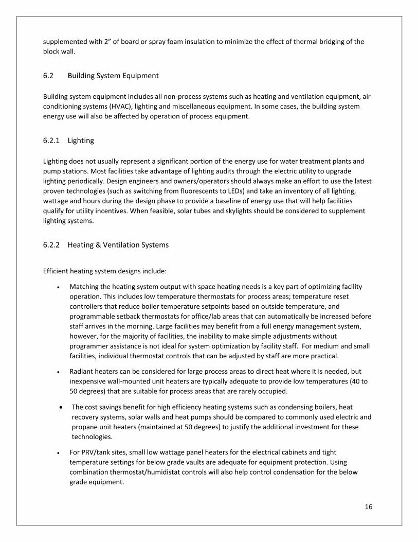
6.2.2 Heating & Ventilation Systems
Efficient heating system designs include:
Matching the heating system output with space heating needs is a key part of optimizing facility
operation. This includes low temperature thermostats for process areas; temperature reset
controllers that reduce boiler temperature setpoints based on outside temperature, and
programmable setback thermostats for office/lab areas that can automatically be increased before
staff arrives in the morning. Large facilities may benefit from a full energy management system,
however, for the majority of facilities, the inability to make simple adjustments without
programmer assistance is not ideal for system optimization by facility staff. For medium and small
facilities, individual thermostat controls that can be adjusted by staff are more practical.
Radiant heaters can be considered for large process areas to direct heat where it is needed, but
inexpensive wall-mounted unit heaters are typically adequate to provide low temperatures (40 to
50 degrees) that are suitable for process areas that are rarely occupied.
The cost savings benefit for high efficiency heating systems such as condensing boilers, heat
recovery systems, solar walls and heat pumps should be compared to commonly used electric and
propane unit heaters (maintained at 50 degrees) to justify the additional investment for these
technologies.
For PRV/tank sites, small low wattage panel heaters for the electrical cabinets and tight
temperature settings for below grade vaults are adequate for equipment protection. Using
combination thermostat/humidistat controls will also help control condensation for the below
grade equipment.

17
Heat recovery systems should only be specified when continuous ventilation must be provided. To
operate a heat recovery supply and exhaust ventilation system continuously when outside airflow
is not essential, uses more electric energy and exhausts more building heat (heat recovery systems
typically recover 60% of the exhausted heat). A better option is to include VFDs/cycle controls on
ventilation units to allow plant staff to adjust ventilation airflow based on requirements.
Adequate ventilation is needed to minimize condensation for some stations. However, tight
temperature setpoints and ventilation fan systems that are activated with humidistats or timers
should be considered. Specifying dampers with tight seals is also recommended for maintaining
low energy costs.
Strategies used by some New Hampshire water plants to reduce building heating costs include:
One water treatment plant uses a heat recovery system that exhausts warm air from a compressor
room to help heat adjacent process areas.
Wall/roof ventilation openings include outside louvers and inside motor operated dampers with
tight closure blades and seals.
All unit heaters include wall thermostats with minimum temperature settings of 40 degrees.
High/low knobs are not used on any pump station electric heater. This includes small pump stations
and control panel heaters.
100-watt electrical panel heaters are used instead of 3,000 to 5,000-watt space heaters for outdoor
electrical panels where only moisture protection is required.
For pump station space heating, outdoor air source heat pumps can provide heating, cooling and
dehumidification.
High kW duct heaters have been removed at some facilities. These large heaters are typically sized
for maximum airflows and can contribute to high facility electric demand costs during the winter
months.
Some process systems may not need heated buildings. Using low cost 100-watt electric panel
heaters are very effective to protect electrical panels without heating the entire space.
Maintenance buildings with separate heated/unheated bays to allow for cold storage. In heated
bays, water piping can be heat traced and insulated to allow for low room temperatures.
Tankless water heaters are used instead of standard electric hot water storage tanks.
6.2.3 Dehumidification
Pipe condensation can be an issue for water plants, pump and PRV stations. The dehumidification
equipment options considered by engineers include commercial dehumidifiers, heat pumps, exhaust fans,
and residential dehumidifiers. An alternative to using dehumidification equipment is to insulate the water
piping (typically not specified since corrosion can occur under the insulation) or using electric unit heaters
during the summer months (the least efficient approach).

18
There is no one solution that is right for all water plant buildings/pump station applications. Based on
efficiency and simplicity, the energy use of an energy star rated residential dehumidifier can be comparable
to some heat pump options depending on the rated coefficient of performance (COP). For new
construction the most cost effective option may be to combine heating and dehumidification in one
efficient heat pump unit.
Regardless of the equipment choice, the most important component of the system is a quality humidistat
to maintain dehumidification energy use as low as possible by setting the humidistat at the highest level to
only activate equipment when required.
6.2.4 Domestic Hot Water
Domestic hot water for water treatment plants, pump stations and PRV stations is typically only required
for intermittent use. Depending on the flow and temperature requirements for eyewash and emergency
showers, on-demand electric, propane or natural gas hot water heaters are the ideal solution for
bathrooms and eyewash stations. Hot water tank systems should include insulation blankets and can be
enhanced with roof mounted solar hot water systems to reduce energy costs.
6.3 Emergency Generators
Emergency generators typically use more energy over the equipment life than the generator ever
produces. To minimize the energy use for these systems, the following is recommended.
Block heaters should be maintained at the lowest level acceptable to the manufacturer.
Consideration should be given to specifying block heaters with circulating pumps and tight
temperature controls that activate the heaters at 100 degrees and de-activate at 120 degrees.
Propane and diesel fuel should be the preferred fuel source over natural gas for emergency
generators to avoid monthly utility charges that can amount to over $1,000 annually.
Generators qualified as Level 1 or 2 by NFPA 110 should be exercised for 30 minutes under load
once per month. Additional generator exercising can be performed if recommended by the
manufacturer, however, exercising a generator beyond these recommendations can result in
excessive fuel costs.
7.0 Renewable Energy
Municipalities often pursue renewable energy as the first option to reduce energy costs. However, the 20+
year simple payback of most renewable energy systems should only be considered after a comprehensive
review of all potential energy efficiency improvements. After all cost-effective efficiency projects are
performed, renewable energy can be pursued to offset the remaining energy use and reduce the building
carbon footprint. A brief summary of the most common renewable energy projects is provided below.
7.1 Net Metering

19
Over the last five years, there have been utility regulation changes in New Hampshire that now allow
customers to receive a net credit for generating on-site power (100 kW maximum rating) to reduce their
energy bill through net metering. The regulations include a provision to allow “group” or aggregate
metering for customers with multiple sites to generate power at one location and apply the excess power
created at other utility account locations. For municipalities, this is ideal to help reduce energy use/cost at
multiple town buildings using renewable energy systems installed at water and wastewater facilities. Large
solar arrays and water system hydro turbine renewable energy systems have worked well for several New
Hampshire municipalities that have taken advantage of net metering.
7.2 PV Solar Systems
Solar photovoltaic (PV) panels have been installed at multiple New
Hampshire water and wastewater facilities. Some municipalities have
contracted with firms that install the systems with no upfront costs if
the facility agrees to a long term purchase contract at reduced kWh
rates. Other approaches include design work and installation with
local contractors or working with national solar panel firms. If
design/installation costs are low and project grants can be obtained,
these projects can be a worthwhile investment after plant process
systems are optimized.
With net metering available in New Hampshire, this is not a site-specific project that must be installed at a
municipal water plant to take advantage of the high pump system energy load. Solar panels can be installed
on any municipal property since the power generated can be allocated to all municipal facilities when the
system capacity is less than 100 kW.
7.3 Transpired Solar Wall Collectors
A transpired solar collector consists of a thin, metal panel mounted a few inches off a south-facing
wall, which creates an air cavity that absorbs the sun's heat as air passes through the small holes in the
panel. A space behind the perforated wall allows the air streams from the holes to mix together. The
heated air is then pulled out from the top of the space into the building. These “low tech” solar projects
work well at water and wastewater facilities and typically have a simple payback of less than 10 years
without grants if installation costs can be kept low.
7.4 Wind Turbines
Wind is also a popular option discussed by municipal officials. However, even with an ideal location these
systems are not cost effective (+30 year payback) without significant grants.
7.5 Hydro Turbines
Hydro turbines can be an opportunity for a municipal water system with high elevation reservoirs/tanks.
The combination of constant flow and high pressure that would otherwise need to be reduced with
Exeter High School 98 kW Solar Array
20
pressure reducing valves is an ideal system for a small hydro turbine application. However, these projects
can have high simple paybacks (+20 years).
8.0 Utility Rate Schedules & Fuel Costs
8.1 Electric Utility Rate Schedules
New Hampshire electric utilities include energy consumption (kWh), peak demand charges and occasionally
power factor penalties. NH design engineers currently make an effort to minimize energy consumption
costs by recommending high efficiency equipment and VFDs. However, most designs do not include
additional features to minimize peak electrical demand, take advantage of off-peak rates and reduce power
factor charges.
8.1.1 Demand Charges
The monthly peak demand charge is based on the highest average kW use over a 30-minute or 15-minute
period (depending on the utility). There are several strategies that can be incorporated into new designs to
help facilities avoid high demand charges.
During the winter months, high kW electric heaters can be interlocked with intermittent pumping
equipment to alternate equipment. Using propane/natural gas unit heaters instead of electric heat
also minimizes electric demand charges. A cost benefit review will help determine the most cost
effective option.
For oversized equipment with VFDs, the VFDs can be programmed to operate at a lower speed to
minimize facility peak demand.
Other non-critical equipment can be alternated to minimize impact on demand charges. This may
include ventilation systems, block heaters and water filtration backwash pumps that automatically
deactivate when other critical equipment is operated.
Strategies to shift electrical demand (such as backwashing filters during the evening) will only reduce
demand charges when the facility rate schedule has a lower cost off-peak demand charge.
8.1.2 Power Factor Correction
Power factor is defined as the ratio of real power to apparent power. In a purely resistive circuit, such as an
incandescent light, the two are equal and power factor is unity or 1.0. In a circuit with inductive loads such
as an AC induction motor, there is reactive energy present (kVAR) and apparent energy (kVA). As power
factor decreases, the kVA value increases more than the real energy (kW). When the power factor is below
a value specified on the utility rate schedule (usually 0.85), a penalty may be added to the bill.
Power factor costs can be found on electric rates for Eversource Large Service Users, Liberty Utility
commercial rates and for some New Hampshire municipal electric utilities. This penalty can be recognized
when the demand charge is billed based on kVA instead of kW.

21
Facilities that have poor power factor can reduce charges by adding capacitance to the electrical
distribution system to increase kVAR, bringing the power factor closer to unity (1.0). This investment
typically has a fast payback (2 to 3 years). Variable frequency drives can also provide the additional benefit
of improving power factor enough to avoid utility penalties (for rate schedules that use kVA to determine
demand charges).
8.1.3 Off-Peak Rates
New Hampshire electric utilities offer time of day (TOU) rate schedules that provide lower energy rates
during off peak hours and higher rates during on-peak hours (for example 7:00 AM to 11:00 PM for the
NHEC Commercial Rate Schedule TOU and 7:00 AM to 8:00 PM for the Eversource “G” TOU Rate Schedule).
These rate schedules can also have on peak/off peak demand charges that provide additional savings.
Several New Hampshire water systems that have adequate water storage available have been able to take
advantage of these rates with annual cost savings exceeding 25%. As part of system upgrades, sizing water
storage and including controls to activate/deactivate pumps based on a timed cycle would provide water
utilities with the option of pursuing this alternative operating mode.
The North Conway Water Precinct (NWCP) has been operating system wells on a time-of-use rate schedule
for years and reduced energy costs by $30,000 in 2018. As of March 2020, this operating strategy has been
recommended for the Conway Water System, Antrim/Bennington Water System and Bristol Water System.
All of these systems have adequate tank capacity to implement the off-peak operation strategy.
8.2 Fuel Source for Space Heating & Emergency Generators
When selecting a fuel source for space heating and back-up emergency generators, the design engineer
should consider the following to minimize costs.
With building related operational parameters and efficiency issues being equal, (component
efficiency, building temperature, building envelope heat loss, etc), the cost/MBTUs for natural gas
has been historically lower than other fuels and electric resistance heat. Natural gas can be a cost
effective choice for heating large buildings. However, when natural gas is used for small buildings
or as a fuel source for emergency generators, the high monthly service fees make this option a
costly fuel source. All utility monthly fees and the annual fuel use should be reviewed before
considering natural gas as a fuel source.
Propane should be considered for pump stations/buildings that require space heating and
emergency generators. For these applications, the cost of purchasing the propane tank can also
be justified for multiple end use applications. Unit costs can be reduced with negotiated annual
contracts.
Compared to electric unit heaters or a central boiler/furnace using natural gas/propane or fuel oil,
propane or natural gas wall mounted unit heaters can be a cost effective approach to heat large
process areas/maintenance shops with low temperature requirements.

22
Instead of using electric resistance unit heaters, heat pumps should be considered for
small/medium size buildings or office areas. The cost/MBTU for space heating and cooling is very
cost effective for these applications.
Facilities that have multiple site buildings with independent heating systems should pursue separate
submeters (for natural gas systems these submeters should be owned by the water utility), separate
propane bills, or separately tracked fuel oil bills to accurately track energy usage for each building and raise
energy use awareness.
9.0 Documentation
New Hampshire water system operators are challenged to operate their systems efficiently when there is a
lack of documentation providing guidance on how to operate system equipment efficiently, and what data
is needed to benchmark system efficiency on a routine basis. This effort starts with including more
equipment performance data in the O&M manuals, and continues with sample tables and data collection
practices to help municipalities operate system equipment efficiently.
9.1 O&M Manual
Process optimization guidance should be included for each O&M Manual section. Useful information for
each section can include:
Discussion of how alternating equipment operation can reduce the peak electrical demand. In
some cases, this can be programmed using typical SCADA controls (such as cycling a filter backwash
operation during the evening).
Details on what process / equipment data is useful to benchmark the efficiency of each process.
Including equipment performance curves and how varying conditions will impact equipment
efficiency.
Guidance for basic VFD functions and navigating electric submeter menus. Including specific VFD
parameters (such as min & max operating range) and the basis for each programmed value.
The engineer is encouraged to offer standard operating procedures (SOPs) based on what is learned during
the equipment commissioning/start-up, process optimization efforts, and how system operation relates to
energy and other O&M costs. When SOPs are developed, they should include details on system
optimization and energy use estimates for various operating modes.
9.2 Benchmarking
Energy benchmarking can be accomplished using internal or external comparisons. Internal benchmarking
allows an organization to evaluate facility energy use year to year to monitor facility efficiency changes. The
results can be used within an organization to track performance over time, identify best practices and
increase management’s understanding of how to analyze and interpret energy data.

23
For external benchmarking, a facility can be compared to similar regional facilities. When process and
energy use data is assembled, the information can be used to assess performance and encourage staff to
investigate why performance is lower than expected, or to confirm efficiency efforts by receiving a high
performance rating relative to other facilities.
The starting point for all New Hampshire water facilities is to collect monthly energy use (kWh) from the
electric bills and benchmark this data with monthly pumped flow (MG). This data does not require
additional costly instrumentation and does not require a spreadsheet. Additional benchmarking can be
done for fuel costs (collecting monthly or seasonal fuel use data and comparing with average outside
temperatures/thermostat settings). Pump efficiency benchmarking typically requires additional power
instrumentation.
Benchmarking is a tool that increases energy awareness for staff. The analysis is simply to compare the
data on a routine basis and evaluate if the monitored systems are becoming more efficient or less efficient
and why these changes are occurring (for example, operating a well VFD at a slower speed thinking that
this action may save energy can actually decrease pump efficiency and increase the kWh/MG benchmark
value).
9.3 Non-Revenue Water
Water loss control represents the efforts of water utilities to
provide accountability in their operation by auditing their
water supplies and implementing controls to minimize
system losses.
Losses include the physical escape of water from the piping
system and losses due to inaccurate metering of customer
consumption, theft of service, and the utility’s own errant
billing and accounting practices; all of which are collectively known as apparent losses. Non-revenue Water
(NRW) includes the real plus apparent losses, along with unbilled authorized consumption, which
represents water used in miscellaneous activities such as hydrant flushing.
To begin the process of becoming more aware of non-revenue water (leakage, un-metered municipal use,
flushing), a municipality should begin the process by tracking quarterly (or even monthly) pumped gallons
with billed gallons to help quantify NRW and use benchmarking data (kWh/MG) to estimate energy savings.
The NHDES water conservation goal of 15% or less non-revenue water can be compared with the collected
data to justify pursuing NHDES leak detection survey grants and provide more accountability to meter flow
for flushing or other maintenance activities.
10.0 Energy Guidance Document Implementation
The emphasis of this document is to outline potential cost effective energy efficiency/ cost saving
improvements, equipment metering, and O&M support that can be proposed by design engineers for
facility upgrades. The document emphasizes accountability and evaluating each efficiency related
improvement based on field data or reasonable estimates for the proposed equipment.

24
As projects move forward, communication between the client, NHDES and the engineer can be beneficial
to quantify the savings for potential utility incentives and energy technical assistance available through the
NHDES.
10.1 Energy Guideline to Evaluate Project Cost Effectiveness
Energy efficiency improvements are based on energy consumption savings (kWh reduction), natural gas,
fuel oil and propane (unit savings), and energy demand (kW savings). A simple payback approach is typically
adequate when energy savings can pay for the project within 10 years. A life cycle cost analysis approach is
recommended when multiple improvement options are available or when comparing large-scale capital-
intensive projects for system upgrades.
The cost for an energy project should only include equipment/controls directly related to the energy
efficiency improvement. Including the cost for redundant equipment, aging infrastructure/ electrical
system upgrades or other improvements that do not have a direct impact on energy savings should not be
included in the cost effectiveness review. This approach is agreeable to utilities when evaluating if an
energy project qualifies for utility incentives. There may be occasions when varying size pumps may need to
be paired up to achieve efficiency at different flow rates. For these equipment configurations, all the pump
units needed to handle normal system operation efficiently should be included in the analysis.
10.2 Initiatives to Develop Energy Efficiency Projects
Recommended initiatives to help engineers work with clients to develop energy efficiency projects include
the following:
For water system upgrades, consider recommending an energy evaluation that will provide a
facility baseline energy use and potentially identify additional energy related projects that can be
added to the scope of work. Pursuing the energy evaluation before work begins provides the
opportunity to also qualify cost effective projects for utility incentives.
Use the recommendations in this guidance document to show clients the value of SCADA
enhancements, electric/fuel submeters, and pressure and flow instrumentation that will allow staff
to monitor pump efficiency on a regular basis.
Identify value added services discussed in the guidance document that can be included as an option
in the scope of work. This can include an enhanced O&M manual with guidance to optimize pump
system operation (illustrated using the existing pump curve), developing SOPs for pump efficiency
tests, and simplified VFD placards mounted on the panels to help operators with basic VFD menu
navigation.
Promoting energy awareness and highlighting cost effective energy efficiency upgrades throughout the
design process, will provide clients with the assurance that the design engineer is providing a thoughtful
design that is mindful of municipal budgets and operating costs after the project is completed.

25
“Energy-saving technologies keep improving faster than they’re applied, so efficiency is an ever
larger and cheaper resource.”
— Amory Lovins


