7
ni.com/awr NI AWR Software Product Portfolio
| Date post: | 09-May-2018 |
| Category: |
Documents |
| Upload: | trinhnguyet |
| View: | 217 times |
| Download: | 1 times |
ni.com/awr
NI AWR SoftwareProduct Portfolio

Powerful, Innovative UI
An intuitive yet powerful design
environment unleashes engineering
productivity, allowing designers to
address the emerging communication
and radar systems driving today’s RF/
microwave hardware developments and
integration technology. System-aware
simulation helps these technologists
investigate and understand the
connection between component and
system performance. From exploring
new, spectrally effi cient architectures for
better performance to specifying and
verifying individual component
requirements within next-generation
systems, today’s high-frequency
electronics must be developed with
simulation and test tools that provide
whole system results.
Robust Simulation Technologies
Advanced simulation technologies
provide fast, accurate results with fully
integrated system, circuit, and EM
analyses that accurately predict and
optimize component performance
before prototype manufacturing and
test, saving development time and
costs. For high-frequency components,
designers must be able to analyze the
design details that will impact electrical
behavior, including transistor
nonlinearities, sensitivity to terminal
impedance mismatch, dispersion,
parasitic coupling, and a host of other
high-frequency phenomena. Simulation
technology must support detailed device
modeling and the same performance
measurements used to specify the
device requirements.
Automation and User Productivity
Design fl ow automation connects
simulation models, third-party tools and
layout geometries to manufacturing
processes. As designs move from early
concept through engineering sign-off,
design details increase and emphasis
switches from electrical performance to
yield and design for manufacturing
concerns, including design rule checking
and layout versus schematic. Design
fl ows are specifi c to PCB, MMIC, RFIC,
and multi-chip module fabrication
processes, requiring specialized support
through process design kits and support
for import/export of layout data such as
GDSII and DXF or fi le formats such as
IPC-2581 or ODB++ for interoperability
with enterprise layout tools.
NI AWR SoftwareWireless Design: Trends and ChallengesNext-generation wireless devices, communications infrastructure, and aerospace/defense electronic systems are creating new
opportunities for engineers to design and develop RF/microwave products. These opportunities are contingent on delivering devices
that achieve high performance goals for bandwidth, linearity, and effi ciency while meeting market requirements for smaller, lighter,
more reliable, and less costly devices. Furthermore, these challenges are compounded by business concerns such as escalating
development costs, limited engineering resources, and time-to-market pressures.
To fulfi ll product requirements, new semiconductor, PCB, and module technologies must achieve unprecedented integration and
functionality within an increasingly smaller form factor. Therefore, engineers are demanding EDA tools that can:
■ Accurately predict electrical performance as it relates to physical design
■ Correctly account for excitations from complex waveforms used in communication and radar systems
■ Offer a seamless flow-to-manufacturing process
To address these trends and challenges, NI AWR Design Environment provides engineers with an integrated, open platform offering
system, circuit, and EM simulation to accelerate the development of high-performance products.
EDA Software: AWR Advantages
Learn more at ni.com/awrAWR
“With intense time-to-market pressures, our designers need proven design fl ows that work seamlessly.NI AWR Design Environment fi lls this need.”
Dr. Simon Mahon, MACOM
Analyst-MP
AntSyn
Ad
ditio
nal P
rod
ucts
NI AWR Design EnvironmentMicrowave Offi ce
Visual System Simulator
Analog Offi ce
AXIEM
Analyst
Ad
d-O
n P
rod
ucts
AWR Connected
iFilter
iMatch
RDR
RFP
TestWave
W5G
Wireless Communications Semiconductor Aerospace/Defense Consumer Electronics Biomedical Automotive Academia

Microwave Offi ceRF and Microwave Circuit Design Software
Advantages Accelerate Design Starts
Powerful design assistance tools such as fi lter, mixer, passive component,
transmission line, and matching network synthesis, along with industry-leading
load-pull analysis for power amplifi er design, provide critical support for all
phases of product development.
Key Analyses
Fast and accurate simulation technology offers robust circuit analysis and
design insight, providing the linear/nonlinear time- and frequency-domain
measurements required to properly characterize and optimize high-frequency
electronics.
Simulation-Ready Models
Comprehensive libraries of high-frequency distributed transmission models, surface-mount vendor components, and process design
kits from leading MMIC/RFIC foundries let engineers accurately simulate designs as they will be manufactured for greater success.
Capabilities
Products Products
Smarter Design Entry
The unifi ed layout editor and schematic
capture with RF-aware model libraries
link electrical design and physical layout,
ensuring greater simulation accuracy
while allowing designers to visualize
products before manufacture.
Parametric control and circuit hierarchy
support development of complex
structures from user-generated building
blocks, as well as design optimization
and re-use.
Insightful Simulation
Analyze key performance metrics of RF
and microwave circuits with frequency-
domain linear simulation for RF/
microwave passive component and
signal integrity applications and the
APLAC harmonic balance/transient
circuit simulation engine for nonlinear
and digitally-modulated circuits such as
power amplifi ers, mixers, and oscillators.
Design for Manufacturing
A leading front-to-back MMIC design
fl ow that enhances engineering
productivity and ensures fi rst-pass
success is provided within a hierarchical
framework that accurately captures the
combined electrical performance
of diverse IC and PCB process
technologies, complex multi-
layer interconnects, embedded passives,
and surface-mounted devices found in
today’s multi-chip RF modules.
Features at a Glance ■ Schematic/Layout – Design entry with industry-leading tuning
■ APLAC – Linear and nonlinear circuit simulation
■ EM Analysis – Fully integrated EM with AXIEM and Analyst
■ Load-Pull – State-of-the-art load-pull analysis
■ Stability – Includes both linear and nonlinear stability analysis
■ DRC/LVS – Design rule checking/layout vs. schematic
■ TX-LINE – Interactive calculator for transmission line analysis
NI AWR Design EnvironmentIntegrated, Open Platform for RF/Microwave Product Development
AdvantagesIntegrated Design
Achieve successful high-frequency circuit and system product development
from initial concept through fi nal verifi cation with powerful electrical/layout
design capture and fully integrated system, circuit, and EM co-simulation.
Intuitive
Software developed by people who understand how RF/microwave products
are designed and built offers an environment that simplifi es complex tasks,
reduces manual design entry, and supports state-of-the-art design fl ows.
Open Platform
Design fl ow automation and interoperability with third-party tools enable
product development to proceed unabated with less hassle and greater
fi rst-pass success. The software’s COM API and scripting allow design teams
to further automate and customize new capabilities within the platform.
CapabilitiesUnifi ed Design Capture
Provides front-to-back design fl ow for
MMIC, RFIC, PCB, and module process
technologies, enhancing productivity and
fi rst pass success with an innovative
user interface and dynamically-linked
electrical and layout design entry.
Superior Design Management
Integrates circuit, system, and EM
simulation technologies within a
comprehensive platform
offering physical layout linked to
simulation-ready schematic capture,
supporting complex hierarchical projects
and virtual test benches.
Design Flow Automation
Supports third-party interoperability with
industry-standard tools, allowing
seamless exchange of design data for
schematic/netlist import, bi-directional
EM co-simulation, ERC/DRC/LVS, and
production-ready GDSII export.
NI AWR Design Environment Platform ■ Microwave Office – RF and Microwave Circuit Design
■ Visual System Simulator – RF Communication and Radar System-Level Design
■ Analog Office – Analog/RFIC Circuit Design
■ AXIEM – 3D Planar EM Analysis
■ Analyst – Full 3D FEM EM Analysis
AWR
“The power and speed of NI AWR Design Environment software made it possible to accurately and effi ciently simulate the entire structure of this very complex NDPA MMIC.”
Dr. Chuck Campbell, Qorvo
Layout
CircuitDesign
SystemDesign
Simulation& Analysis
DRC/LVS
EM/Extraction
AWR
n RF Devices (Amplifi ers, Filters, Passives, Control)
n MMICs (III-V Compound Semiconductors)
n RF and High-Speed PCBs
n Multi-C hip Modules
Applications
Analog Offi ceAnalog/RFIC Circuit Design Software
AdvantagesRF Focused
A powerful yet cost-effective RFIC design platform that enables fast and
accurate entry of design concepts, supporting design management with
parasitic-aware component models, analyses, and design assistance that helps
engineers study and understand the interdependencies of analog, RF, and
mixed-signal design.
RFIC Extraction
Analog Offi ce works with iNet and ACE to perform interconnect modeling and
parasitic extraction of IC structures created with the integrated layout editor or
imported GDS II layouts from 3rd party IC layout tools.
IC Design Ecosystems
Analog Offi ce is fully integrated within the NI AWR Design Environment open platform, allowing designers to exchange design data
between third-party IC layout and EM simulation tools. The Open Access import/export wizard transfers design schematic data
between Analog Offi ce and Cadence Virtuoso, supporting the transfer of IP between tools.
Capabilities
Products Products
RFIC Design Flow
Provides comprehensive simulation
of RFIC technologies from system to
fi nal tapeout. The RF/microwave-aware
active and passive device models, silicon
foundry PDKs, and support for
Spectre netlist simulation accurately
capture the behavior of RF front-end
blocks within an RFIC design, either as a
stand-alone tool or as supplemental
simulation software within a Cadence
Virtuoso design fl ow.
High Frequency Simulation
Provides frequency-domain, harmonic
balance, and transient simulations for
small-scale RFICs and RF front-end
blocks within large-scale RFICs to
effi ciently predict the performance of
high dynamic range RF circuits operating
at RF, microwave, and millimeter-wave
frequencies for wireless communication
and radar applications.
Silicon PDKs
PDKs for leading silicon foundries are
developed for the open NI AWR Design
Environment from foundry-supplied
technology fi les, device models, and
design rules. These PDKs are subjected
to extensive validation at both cell and
circuit level to ensure quality and
conformance to best-in-class design
methodologies for high-frequency RFIC
designs, accelerating silicon tapeouts
and enabling fi rst-pass success.
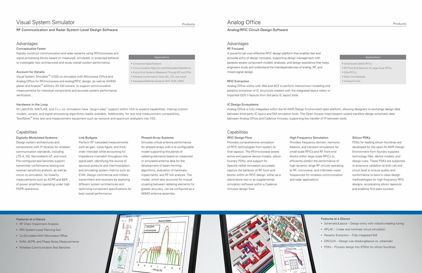
Visual System SimulatorRF Communication and Radar System-Level Design Software
AdvantagesConceptualize Faster
Rapidly construct communication and radar systems using RF/microwave and
signal processing blocks based on measured, simulated, or projected behavior
to investigate new architectures and study overall system performance.
Account for Details
Visual System Simulator™ (VSS) co-simulates with Microwave Offi ce and
Analog Offi ce for RF/microwave and analog/RFIC design, as well as AXIEM
planar and Analyst™ arbitrary 3D EM solvers, to support communication
measurements for individual components and accurate system performance
verifi cation.
Hardware in the Loop
NI LabVIEW, MATLAB, and C++ co- simulation have “plug-n-play” support within VSS to expand capabilities, making custom
models, scripts, and signal processing algorithms readily available. Additionally, for test and measurement compatibility,
TestWave™ links test and measurement equipment such as network and spectrum analyzers into VSS.
CapabilitiesDigitally-Modulated Systems
Design system architectures and
components with IP libraries for wireless
communication standards, including
LTE-A, 5G, Narrowband IoT, and more.
Pre-confi gured test benches support
transmitter conformance testing and
receiver sensitivity analysis, as well as
circuit co-simulation, for linearity
measurements such as ACPR and BER
of power amplifi ers operating under high
PAPR operations.
Link Budgets
Perform RF-cascaded measurements
such as gain, noise fi gure, and third-
order intercept while accounting for
impedance mismatch throughout the
signal path, identifying the source of
spurious products and intermodulation,
and simulating system metrics such as
EVM. Design commercial and military
transmitters and receivers by exploring
different system architectures and
optimizing component specifi cations for
best overall performance.
Phased-Array Systems
Simulate critical antenna performance
for phased arrays with a re-confi gurable
model supporting thousands of
radiating elements based on measured
or simulated antenna data for the
development of beam-forming
algorithms, evaluation of hardware
impairments, and RF link analysis. The
model, which also accounts for mutual
coupling between radiating elements for
greater accuracy, can be confi gured as a
MIMO antenna assembly.
Features at a Glance ■ RF Chain Impairment Analysis
■ RFA System-Level Planning Tool
■ Co-Simulates With Microwave Office
■ EVM, ACPR, and Phase Noise Measurements
■ Wireless Communication Test Benches
Features at a Glance ■ Schematic/Layout – Design entry with industry-leading tuning
■ APLAC – Linear and nonlinear circuit simulation
■ Parasitic Extraction – Fully integrated EM
■ DRC/LVS – Design rule checking/layout vs. schematic
■ PDKs – Process design kits (PDKs) for silicon foundries
n Component Specifi cations
n Communication Algorithm and Modulated Waveforms
n End-to-End Systems (Baseband Through RF and OTA)
n Wireless Conformance Tests (5G, LTE, and more )
n Aerospace/Defense Systems (EW, ECM, ESM)
Applications
n Small-Scale CMOS RFICs
n RF Front-End Sections of Large-Scale RFICs
n SiGe RFICs
n Multi-Chip Modules
n Analog Circuits
Applications

AnalystFull 3D Finite Element Method EM Analysis Software
AdvantagesDiagnostics and Design
Electromagnetic simulation can detect design problems that cause
products to fail performance requirements. With
3D EM simulation easily available within an RF/microwave design fl ow,
engineers can identify and eliminate potential design failures.
Parametric Cells
Libraries of parameterized EM cells for common and custom
3D interconnects and passive PCB and IC components allow designers to
incorporate with a simple drag and place true electrical responses in real time
during the design process.
Robust Solver
A full 3D FEM solver technology with adaptive volumetric tetrahedral meshing, direct and iterative solvers, and discrete and fast-
frequency sweeps to accurately characterize interconnect structures, dense circuitry, and antenna structures.
Capabilities
Products Products
3D Modeling
Proprietary FEM solver technology
supports simulation of arbitrary 3D
structures, including thin and thick
metals, fi nite dielectrics, and surface
roughness, addressing structures such
as MMIC, RFIC, PCB, and module-
based designs and related interconnects
such as wire-bonds and ball grid arrays,
as well as waveguides, coaxial
connectors, and hybrid circuit housings.
Design Exploration
Improve performance and mitigate
design problems from unforeseen
resonances and coupling between
structures automatically with 3D EM
parametric studies, supporting
optimization, tuning, and yield analysis.
Domain and spectral decomposition
combine with remote computing to
expedite simulation run times and
provide answers faster.
Antenna Analysis
Analyze 3D and 2D antennas, including
patch antennas/arrays on fi nite
dielectrics, plotted near- and far- fi eld
radiation patterns, gain plots, return
loss, and surface currents. Designs can
be created with the 2D and/or 3D
editors, converted from an AXIEM
structure, or imported from ACIS, Step,
and IGES fi les.
AXIEM3D Planar EM Analysis Software
AdvantagesFast and Accurate
Fast, adaptive hybrid meshing technology supports thick-metal structures and
vias, automatically fracturing structures into triangular and rectangular elements
for maximum accuracy and robust broadband results, from DC to daylight.
Unparalleled Integration
AXIEM is seamlessly tied to circuit and system simulation, layout, and
verifi cation through the proprietary AWR unifi ed data model (UDM), enabling
direct EM extraction without having to perform explicit layout and EM simulation
setup steps and directly incorporating results into circuit and/or system
simulations.
Versatile
Extensive sources/ports, including auto-calibrated internal ports and de-embedding options, provide greater fl exibility and accuracy for
structures with embedded circuit-based, lumped-element components and active devices such as transistors.
CapabilitiesPassive Modeling
Provides 3D planar EM simulation of
transmission lines and arbitrary
structures on single and multi-layer
circuits using method-of-moments
(MoM) technology with advance
meshing to accurately compute S-, Y-,
and Z-parameters, as well as current
densities of multilayer RFICs, MMICs,
PCBs, hybrids, and MCMs.
Planar Antenna Design
Perform analysis and post-processing
of planar antennas and planar arrays.
The fast N*Log(N) solver technology
addresses large, complex arrays that
were previously impractical to simulate
in their entirety. Post-processing
includes the ability to show currents on
antennas and 2D/3D far-fi eld antenna
pattern measurements for linear, circular,
and elliptical polarizations.
Optimization and Yield
Perform accurate design diagnostics
such yield analysis and optimization for
passive components and complex
interconnects, capturing true coupling
and parasitic effects of circuit topologies
that are specifi ed parametrically and/or
defi ned through rules-based shape
modifi ers/de-featuring.
Features at a Glance ■ Layout/Drawing Editor – 2D and 3D views
■ Proprietary Method-of-Moments Technology
■ Meshing Technology – Automatic adaptive meshing
■ Numerous Sources and Excitations
■ Visualization and Results Post-Processing
■ Parametric Studies – Optimization, tuning, and yield analysis
■ HPC – Multi-core configurations and asynchronous simulation
Features at a Glance ■ Layout/Drawing Editor – 2D/ 3D construction and views
■ Proprietary FEM Full-Wave Technology
■ Meshing Technology – Automatic and adaptive meshing
■ Numerous Sources and Excitations for Ports
■ Visualization and Results Post-Processing
■ Parametric Studies – Optimization, tuning, and yield analysis
■ HPC – Multi-core configurations and asynchronous simulation
“We chose AXIEM because of its speed, capacity, and accuracy. It helped us deliver a higher performing product in less time.”Shinichi Goto, Toshiba
n On-Chip and Off-Chip Passives
n IC, PCB, and Module Interconnects
n Extraction of Critical Transmission Lines (Nets)
n Design Verifi cation of Layout
n Antenna Design and Analysis
Applications
n On-Chip and Off-Chip Passives
n 3D IC, PCB, and Module Interconnects
n Hierarchical Interconnect, Common to SoC, SiP
n Design Verifi cation of Layout, Including Finite Dielectrics
n 3D Antenna Design and Analysis
Applications

Add-On Products
AWR Connected – A collection of plug-and-play modules that integrates NI AWR software with third-party software/hardware
products to provide a range of solutions for the design of high-frequency products. AWR Connected includes design synthesis, PCB
layout/verifi cation, and EM/thermal analysis, as well as test and measurement connectivity.
Synthesis ■ AMCAD
■ AMPSA
■ Nuhertz
■ Optenni Lab
PCB ■ Cadence
■ DWT
■ Intercept
■ Mentor Graphics
■ Zuken
EM/Thermal ■ ANSYS
■ CapeSym
■ CST
■ Sonnet Software
■ WIPL-D
T&M ■ National Instruments
■ Anritsu
■ Focus Microwaves
■ Maury Microwave
■ Rohde & Schwarz
1994 1998 1999 2000 2001 2002 2003 2005 2006 2007 2008 2010 2011 2012 2013 2015 2016 2017
AWR Founded Unified Data Model (UDM)
VSS Circuit/ System Co-Simulation
X-Models
XML Libraries
EM Socket
APLAC
Multi-Technology Support
ACE
RFA
AXIEM
Memory Effects
TDNN
NI Acquires AWR
Circuit Envelope
Analyst
Load-Pull
AntSyn
Measurement-Driven Simulation
Real-Time Tuning
RFP System-Level Load Pull
MRHB
iFilter™ – An NI AWR Design Environment integrated fi lter synthesis module that runs seamlessly as a wizard within Microwave Offi ce
software. It enables fi lter designers to accelerate design starts with powerful synthesis of lumped and distributed fi lter types, with a
ready transition of the resulting circuit topologies into Microwave Offi ce for further refi nement, optimization, EM verifi cation, and
physical design.
iMatch™ – An integrated impedance- matching module (and sub-component of iFilter) that runs seamlessly as a wizard within
Microwave Offi ce software. It quickly and easily takes the user through the process of evaluating different matching topologies and
selecting the optimal solution based on certain user-specifi ed requirements.
RDR – A radar test bench and phased-array library module that works seamlessly with VSS software to support radar applications,
including military, medical, weather, and automotive. RDR offers radar signal generation, radar-specifi c target and propagation
modeling, and radar signal processing capabilities.
RFP – A radio-frequency planner wizard that works seamlessly with VSS software as an essential utility for designers of radio
communications systems, cellular, or military radio links, allowing them to effortlessly and effi ciently determine spurious-free
bandwidths.
W5G – A 5G modulation waveforms library that includes test benches and phased-array features. It works seamlessly with VSS
software and gives VSS users access to current 5G candidate signals, each of which can then be implemented as a fully-
parameterizable block with source subcircuits .
Additional Products
AntSyn™ – Web-based antenna synthesis technology for automated antenna design that takes antenna engineering requirements as
input and produces antenna designs as output.
Applications ■ High Efficiency
■ Wire and Planar
■ Phased Arrays
■ Single, Dual, and Multi-Band
■ Broadband and UWB (>100:1)
Features at a Glance ■ Browser-Based Interface
■ Cloud-Based Execution
■ Proprietary Evolutionary Algorithm
■ Diverse Range Of Antenna Types
■ Export to EM Solvers and CAD Tools
“We chose NI AWR software because of the proven success of AntSyn and Analyst. The resulting designs worked from the start and removed the iteration and experimentation usually required in antenna design efforts.”
Mark Ross, Striiv
Analyst-MP – Analyst multi-physics (MP) is an expanded technology suite of Analyst 3D FEM EM focused on big, multi-physics
applications like particle accelerators, waveguides, and complex resonators.
Features at a Glance ■ Layout/Drawing Editor
■ Automatic and Adaptive Meshing
■ Full-Wave, Quasi-Static
■ Multi-Physics Solvers
■ Domain/Spectral Decomposition
■ Visualization/Results Post-Processing
Applications ■ Particle Accelerators
■ Waveguides
■ Cavities
■ Microwave Tubes/Plumbing
■ Resonators
AWR Innovations
PTFL-2017.04.28
©2017 National Instruments. All rights reserved. Analog Offi ce, AWR, AWR Design Environment, AXIEM, Microwave Offi ce, National Instruments, NI, and ni.com are trademarks of National Instruments. Other product and company names listed are trademarks or trade names of their respective companies.
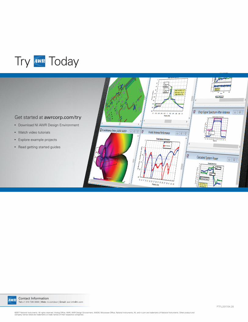
Try AWR Today
Get started at awrcorp.com/try ■ Download NI AWR Design Environment
■ Watch video tutorials
■ Explore example projects
■ Read getting started guides
AWR Contact InformationTel:+1 310 726 3000 | Web: ni.com/awr | Email: [email protected]


