USER GUIDE NI USB-6501 24-Channel, 32-Bit Counter Digital I/O Device The National Instruments USB-6501 is a Full Speed USB 2.0 device that provides 24 DIO channels and a 32-bit counter. This user guide describes how to use the device. For specifications, refer to the NI USB-6501 Device Specifications document available at ni.com/manuals. The following figure shows key functional components of the NI USB-6501. Figure 1. NI USB-6501 Top and Back Views 1 2 2 4 3 NI USB-6501 24-line Digital I/O 1. USB Cable Strain Relief 2. Screw Terminal Connector Plug 3. LED Indicator 4. USB Connector The following figure shows key functional components of the NI USB-6501.
Transcript
USER GUIDE
NI USB-650124-Channel, 32-Bit Counter Digital I/O Device
The National Instruments USB-6501 is a Full Speed USB 2.0 device that provides 24 DIOchannels and a 32-bit counter. This user guide describes how to use the device.
For specifications, refer to the NI USB-6501 Device Specifications document available at ni.com/manuals.
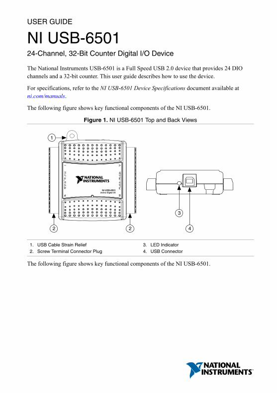
The following figure shows key functional components of the NI USB-6501.
Figure 1. NI USB-6501 Top and Back Views
1
2 2 4
3
NI USB-650124-line Digital I/O
1. USB Cable Strain Relief2. Screw Terminal Connector Plug
3. LED Indicator4. USB Connector
The following figure shows key functional components of the NI USB-6501.
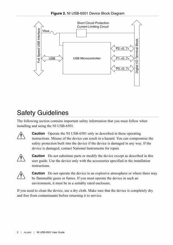
Safety GuidelinesThe following section contains important safety information that you must follow wheninstalling and using the NI USB-6501.
Caution Operate the NI USB-6501 only as described in these operatinginstructions. Misuse of the device can result in a hazard. You can compromise thesafety protection built into the device if the device is damaged in any way. If thedevice is damaged, contact National Instruments for repair.
Caution Do not substitute parts or modify the device except as described in thisuser guide. Use the device only with the accessories specified in the installationinstructions.
Caution Do not operate the device in an explosive atmosphere or where there maybe flammable gases or fumes. If you must operate the device in such anenvironment, it must be in a suitably rated enclosure.
If you need to clean the device, use a dry cloth. Make sure that the device is completely dryand free from contaminants before returning it to service.
2 | ni.com | NI USB-6501 User Guide
Operate the device only at or below Pollution Degree 2. Pollution is foreign matter in a solid,liquid, or gaseous state that can reduce dielectric strength or surface resistivity. The followingis a description of pollution degrees:• Pollution Degree 1 means no pollution or only dry, nonconductive pollution occurs. The
pollution has no influence.• Pollution Degree 2 means that only nonconductive pollution occurs in most cases.
Occasionally, however, a temporary conductivity caused by condensation must beexpected.
• Pollution Degree 3 means that conductive pollution occurs, or dry, nonconductivepollution occurs that becomes conductive due to condensation.
You must insulate signal connections for the maximum voltage for which the device is rated.Do not exceed the maximum ratings for the device. Do not install wiring while the device islive with electrical signals.
Operate the device at or below the Measurement Category I1. Measurement circuits aresubjected to working voltages2 and transient stresses (overvoltage) from the circuit to whichthey are connected during measurement or test. Measurement categories establish standardimpulse withstand voltage levels that commonly occur in electrical distribution systems. Thefollowing is a description of measurement categories:• Measurement Category I is for measurements performed on circuits not directly
connected to the electrical distribution system referred to as MAINS3 voltage. Thiscategory is for measurements of voltages from specially protected secondary circuits.Such voltage measurements include signal levels, special equipment, limited-energy partsof equipment, circuits powered by regulated low-voltage sources, and electronics.
• Measurement Category II is for measurements performed on circuits directly connectedto the electrical distribution system. This category refers to local-level electricaldistribution, such as that provided by a standard wall outlet (for example, 115 V for U.S.or 230 V for Europe). Examples of Measurement Category II are measurementsperformed on household appliances, portable tools, and similar E Series devices.
• Measurement Category III is for measurements performed in the building installation atthe distribution level. This category refers to measurements on hard-wired equipmentsuch as equipment in fixed installations, distribution boards, and circuit breakers. Otherexamples are wiring, including cables, bus-bars, junction boxes, switches, socket-outlets
1 Measurement Category is defined in electrical safety standard IEC 61010-1. MeasurementCategory is also referred to as Installation Category.
2 Working voltage is the highest rms value of an AC or DC voltage that can occur across anyparticular insulation.
3 MAINS is defined as a hazardous live electrical supply system that powers equipment. Suitablyrated measuring circuits may be connected to the MAINS for measuring purposes.
in the fixed installation, and stationary motors with permanent connections to fixedinstallations.
• Measurement Category IV is for measurements performed at the primary electricalsupply installation (<1,000 V). Examples include electricity meters and measurements onprimary overcurrent protection devices and on ripple control units.
Installing the SoftwareSoftware support for the NI USB-6501 is provided by NI-DAQmx or NI-DAQmx Base.
Back up any applications before upgrading your software. You must be an administrator toinstall NI software on your computer. Refer to the NI-DAQmx Readme or the NI-DAQmx BaseReadme on the software media for supported application software and versions.
Complete the following steps to install software:1. If applicable, install an application development environment (ADE), such as LabVIEW,
Microsoft Visual Studio, or LabWindows™/CVI™.2. Install the NI-DAQmx driver or the NI-DAQmx Base driver.
Connecting the DeviceBefore installing the NI USB-6501, you must install the software you plan to use with it.
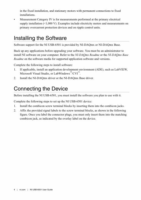
Complete the following steps to set up the NI USB-6501 device:1. Install the combicon screw terminal blocks by inserting them into the combicon jacks.2. Affix the provided signal labels to the screw terminal blocks, as shown in the following
figure. Once you label the connector plugs, you must only insert them into the matchingcombicon jack, as indicated by the overlay label on the device.
1. Overlay Label with Pin Orientation Guides2. Combicon Jack
3. Screw Terminal Connector Plugs4. Signal Name Labels
3. Connect the wiring to the appropriate screw terminals.4. Use the provided USB cable to connect the NI USB-6501 device to your computer.
FeaturesThe NI USB-6501 features USB cable strain relief, an LED indicator, and two screw terminalconnector plugs for I/O.
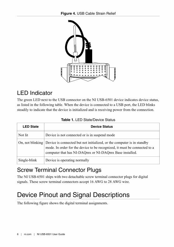
USB Cable Strain ReliefYou can provide strain relief for the USB cable by threading a zip tie through the USB cablestrain relief ring and tightening it around a looped USB cable, as shown in the followingfigure.
LED IndicatorThe green LED next to the USB connector on the NI USB-6501 device indicates device status,as listed in the following table. When the device is connected to a USB port, the LED blinkssteadily to indicate that the device is initialized and is receiving power from the connection.
Table 1. LED State/Device Status
LED State Device Status
Not lit Device is not connected or is in suspend mode
On, not blinking Device is connected but not initialized, or the computer is in standbymode. In order for the device to be recognized, it must be connected to acomputer that has NI-DAQmx or NI-DAQmx Base installed.
Single-blink Device is operating normally
Screw Terminal Connector PlugsThe NI USB-6501 ships with two detachable screw terminal connector plugs for digitalsignals. These screw terminal connectors accept 16 AWG to 28 AWG wire.
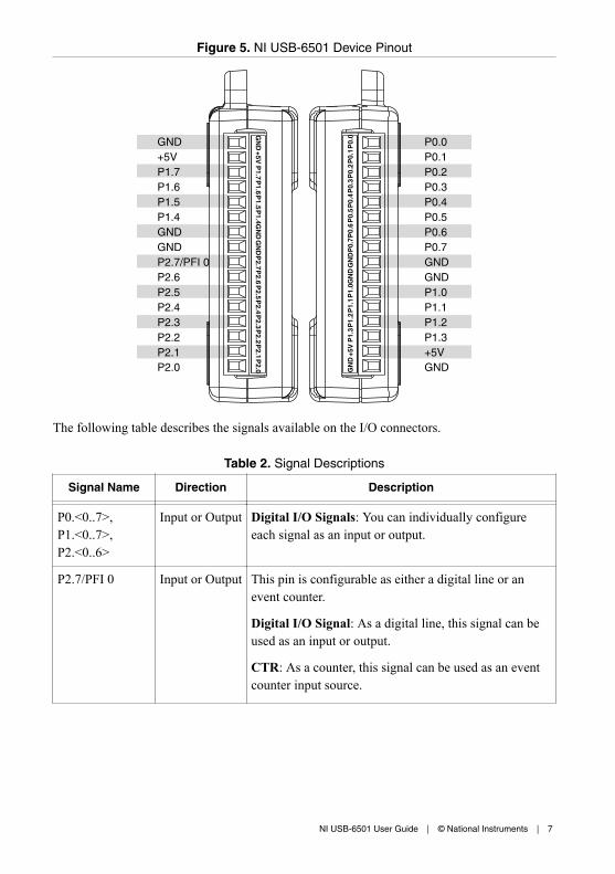
Device Pinout and Signal DescriptionsThe following figure shows the digital terminal assignments.
+5 V Output The voltage source provided by the USB host. Thevoltage is nominally 5 V, but varies from system tosystem.
GND — Ground: The reference for the digital signals and the+5 VDC supply.
Digital I/OThe NI USB-6501 device has 24 single-ended digital lines that comprise the three DIO ports:P0.<0..7>, P1.<0..7>, and P2.<0..7>. P2.7/PFI 0 can also function as a 32-bit event counter.
Static DIOEach DIO line can be individually programmed as a static DI or DO line. You can use staticDIO lines to monitor or control digital signals. All samples of static DI lines and updates ofDO lines are software-timed.
Digital OutputThe following table shows the correlation between terminology used for hardwarefunctionality and for NI-DAQmx.
Table 3. Hardware and NI-DAQmx Terminology
Hardware Functionality NI-DAQmx Terminology
Open-drain Open collector
Push-pull Active drive
The default configuration of the NI USB-6501 DIO ports is open collector, allowing 5 Voperation, with an onboard 4.7 kΩ pull-up resistor. An external, user-provided pull-up resistorcan be added to increase the source current drive up to a 8.5 mA limit per line, as shown in thefollowing figure.
8 | ni.com | NI USB-6501 User Guide
Figure 6. Example of Connecting an External, User-Provided Resistor
GND
P0.0
+5 V
RpRe
Rl
VBus
4.7 KΩ Onboard Resistor
Load
A
Short Circuit ProtectionCurrent Limiting Circuit
Port Pad
ExternalPull-UpResistor
Additionally, you can configure the DIO ports as active drive. When configured as activedrive, the total current sourced by all DO lines simultaneously should not exceed 65 mA.
Determining the Pull-Up Resistor ValueComplete the following steps to determine the value of the user-provided pull-up resistor:1. Place an ammeter in series with the load2. Place a variable resistor between the digital output line and the +5 V.3. Adjust the variable resistor until the ammeter current reads as the intended current. The
intended current must be less than 8.5 mA.4. Remove the ammeter and variable resistor from your circuit.5. Measure the resistance of the variable resistor. The measured resistance is the ideal value
of the pull-up resistor.6. Select a static resistor value for your pull-up resistor that is greater than or equal to the
ideal resistance.7. Reconnect the load circuit and the pull-up resistor.
Digital I/O CircuitryThe following figure shows some common examples of connections of DIO lines withstandard circuits. In the figure, P0.<0..7> is connected to example signals configured as digitalinputs and digital outputs. You can configure P1.<0..7> and P2.<0..7> similarly.
1. P0.0 configured as an open collector digital outputdriving an LED
2. P0.2 configured as a active drive digital outputdriving an LED
3. P0.4 configured as a digital input receiving a TTLsignal from a gated inverter
4. P0.7 configured as a digital input receiving a 0 Vor 5 V signal from a switch
Caution Exceeding the maximum input voltage ratings or maximum output ratingslisted in the device specifications can damage the DAQ device and the computer.National Instruments is not liable for any damage resulting from such signalconnections.
I/O ProtectionEach DIO signal is protected against overvoltage, undervoltage, and overcurrent conditions, aswell as ESD events. However, you should avoid these fault conditions by using the followingguidelines:• If you configure a DIO line as an output, do not connect it to any external signal source,
ground signal, or power supply.• If you configure a DIO line as an output, understand the current requirements of the load
connected to these signals. Do not exceed the specified current output limits of the DAQdevice.
• If you configure a DIO line as an input, do not drive the line with voltages outside of itsnormal operating range.
• Treat the DAQ device as you would treat any static-sensitive device. Always properlyground yourself and the equipment when handling the DAQ device or connecting to it.
10 | ni.com | NI USB-6501 User Guide
Power-On StatesAt system startup and reset, the hardware sets all DIO lines to high-impedance inputs. TheDAQ device does not drive the signal high or low. Each line has a weak pull-up resistorconnected to it.
P2.7/PFI 0 Event CounterYou can configure P2.7/PFI 0 as the source for a 32-bit counter. In this mode, the devicecounts high to low transitions on P2.7/PFI 0. The counter can be armed and disarmed and thecount can be read or reset through software. Refer to your software documentation for moreinformation about counter programming techniques.
+5 V Power SourceThe NI USB-6501 supplies a nominal 5 V from two pins, one on each screw terminal block.The voltage source is provided by the USB host. The voltage is nominally 5 V but varies fromsystem to system. Refer to the NI USB-6501 Device Specifications for more information aboutUSB bus power specifications. This source can be used to power external components.
Note Output is disabled when the device is in USB suspend.
Caution When using the 5 V source, understand the current requirements of theload connected. Do not exceed the specified limits of the +5 V output currentspecification.
Where to Go from HereThis section lists where you can find example programs and additional documentation for theNI USB-6501.
Example ProgramsThe NI-DAQmx and NI-DAQmx Base software includes examples you can use to get startedprogramming with your device. Examples are also available from ni.com/support. Modifyexample code and save it in an application, use examples to develop a new application, or addexample code to an existing application.
NI-DAQmx Example ProgramsNI-DAQmx examples are available on the software media and from ni.com/support. To runexamples without the device installed, use an NI-DAQmx simulated device. For moreinformation, in Measurement & Automation Explorer (MAX), select Help»Help Topics»NI-DAQmx»MAX Help for NI-DAQmx and search for simulated devices.
NI-DAQmx Base Example ProgramsNI-DAQmx Base examples are available on the software media, from ni.com/support, and areaccessible from Start»All Programs»National Instruments»NI-DAQmx Base»Examples.
Related DocumentationEach application software package and driver includes information about writing applicationsfor taking measurements and controlling measurement devices. The following references todocuments assume you have NI-DAQmx 8.7 or later, NI-DAQmx Base 3.x, and whereapplicable, version 7.1 or later of the NI application software
Refer to ni.com/manuals for the most recent documentation.
NI-DAQmxThe NI USB-6501 Quick Start included with the NI USB-6501 describes how to installNI-DAQmx software, install the device, and confirm that your device is operating properly.
The NI-DAQmx Readme is available from the Windows Start menu and lists which applicationsoftware, devices, and ADEs are supported by this version of NI-DAQ.
The NI-DAQmx Help is available from the Windows Start menu and contains API overviews,general information about measurement concepts, key NI-DAQmx concepts, and commonapplications that are applicable to all programming environments.
NI-DAQmx Base (Linux/Mac OS X/LabVIEW PDA 8.x)The Getting Started with NI-DAQmx Base document describes how to install the NI-DAQmxBase software, the NI-DAQmx Base-supported DAQ device, and how to confirm that thedevice is operating properly on your Windows, Linux, or Mac machine. In Windows, selectStart»All Programs»National Instruments»NI-DAQmx Base»Documentation»GettingStarted with NI-DAQmx Base.
The NI-DAQmx Base Readme lists devices supported in different versions of NI-DAQmxBase. In Windows, select Start»All Programs»National Instruments»NI-DAQmx Base»DAQmx Base Readme.
The NI-DAQmx Base VI Reference Help contains VI reference and general information aboutmeasurement concepts. In LabVIEW, select Help»NI-DAQmx Base VI Reference Help.
The NI-DAQmx Base C Function Reference Help contains C reference and generalinformation about measurement concepts. In Windows, select Start»All Programs»NationalInstruments»NI-DAQmx Base»Documentation»C Function Reference Help.
Note All NI-DAQmx Base documentation for Linux is installed at /usr/local/natinst/nidaqmxbase/documentation. All NI-DAQmx Base documentationfor Mac OS X is installed at/Applications/National Instruments/NI-DAQmx Base/documentation.
LabVIEWIf you are a new user, use the Getting Started with LabVIEW manual to familiarize yourselfwith the LabVIEW graphical programming environment and the basic LabVIEW features youuse to build data acquisition and instrument control applications. Open the Getting Startedwith LabVIEW manual by selecting Start»All Programs»National Instruments»LabVIEW»LabVIEW Manuals or by navigating to thelabview\manuals directory and openingLV_Getting_Started.pdf.
Use the LabVIEW Help, available by selecting Help»LabVIEW Help in LabVIEW, to accessinformation about LabVIEW programming concepts, step-by-step instructions for usingLabVIEW, and reference information about LabVIEW VIs, functions, palettes, menus, andtools. Refer to the following locations on the Contents tab of the LabVIEW Help forinformation about NI-DAQmx:
LabWindows/CVIThe Data Acquisition section of the LabWindows/CVI Help contains Taking an NI-DAQmxMeasurement in LabWindows/CVI, which includes step-by-step instructions for creating ameasurement task using the DAQ Assistant. In LabWindows/CVI, select Help»Contents, andthen select Using LabWindows/CVI»Data Acquisition. This book also contains informationabout accessing detailed information through the NI-DAQmx Help.
The NI-DAQmx Library section of the LabWindows/CVI Help contains API overviews andfunction reference for NI-DAQmx. Select Library Reference»NI-DAQmx Library in theLabWindows/CVI Help.
Measurement StudioIf you program your NI-DAQmx-supported device in Measurement Studio using Visual C# orVisual Basic .NET, you can interactively create channels and tasks by launching the DAQAssistant from MAX or from within Visual Studio. You can use Measurement Studio togenerate the configuration code based on your task or channel. Refer to the DAQ AssistantHelp for additional information about generating code.
The NI Measurement Studio Help is fully integrated with the Microsoft Visual Studio help. Toview this help file in Visual Studio, select Measurement Studio»NI Measurement StudioHelp. For information related to developing with NI-DAQmx, refer to the following topicswithin the NI Measurement Studio Help:• For step-by-step instructions on how to create an NI-DAQmx application using the
Measurement Studio Application Wizard and the DAQ Assistant, refer to Walkthrough:Creating a Measurement Studio NI-DAQmx Application.
• For help with NI-DAQmx methods and properties, refer to NationalInstruments.DAQmxNamespace and NationalInstruments.DAQmx.ComponentModel Namespace.
• For conceptual help with NI-DAQmx, refer to Using the Measurement Studio NI-DAQmx .NET Library and Developing with Measurement Studio NI-DAQmx.
• For general help with programming in Measurement Studio, refer to Getting Started withthe Measurement Studio Class Libraries.
To create an application in Visual Basic .NET or Visual C#, follow these general steps:
ANSI C without NI Application SoftwareThe NI-DAQmx Help contains API overviews and general information about measurementconcepts. Select Start»All Programs»National Instruments»NI-DAQ»NI-DAQmx Help.
The NI-DAQmx C Reference Help describes the NI-DAQmx Library functions, which you canuse with National Instruments data acquisition devices to develop instrumentation, acquisition,and control applications. Select Start»All Programs »National Instruments»NI-DAQ»Text-Based Code Support»NI-DAQmx C Reference Help.
.NET Languages without NI Application SoftwareWith the Microsoft .NET Framework version 2.0 or later, you can use NI-DAQmx to createapplications using Visual C# and Visual Basic .NET without Measurement Studio. You needMicrosoft Visual Studio .NET 2005 or later for the API documentation to be installed.
The installed documentation contains the NI-DAQmx API overview, measurement tasks andconcepts, and function reference. This help is fully integrated into the Visual Studiodocumentation. To view the NI-DAQmx .NET documentation, go to Start»All Programs»National Instruments»NI-DAQ»Text-Based Code Support. For function reference, refer tothe NationalInstruments.DAQmx Namespace andNationalInstruments.DAQmx.ComponentModel Namespace topics. For conceptual help, referto the Using the Measurement Studio NI-DAQmx .NET Library and Developing withMeasurement Studio NI-DAQmx sections.
To get to the same help topics from within Visual Studio 2005 or 2008, go to Help»Contentsand select Measurement Studio from the Filtered By drop-down list. To get to the same helptopics from within Visual Studio 2010, go to Help»View Help and select NI MeasurementStudio Help from the Related Links section.
Training CoursesIf you need more help getting started developing an application with NI products, NI offerstraining courses. To enroll in a course or obtain a detailed course outline, refer to ni.com/training.
Worldwide Support and ServicesThe National Instruments website is your complete resource for technical support. At ni.com/support, you have access to everything from troubleshooting and application developmentself-help resources to email and phone assistance from NI Application Engineers.
Visit ni.com/services for NI Factory Installation Services, repairs, extended warranty, andother services.
Visit ni.com/register to register your National Instruments product. Product registrationfacilitates technical support and ensures that you receive important information updates fromNI.
A Declaration of Conformity (DoC) is our claim of compliance with the Council of theEuropean Communities using the manufacturer’s declaration of conformity. This systemaffords the user protection for electromagnetic compatibility (EMC) and product safety. Youcan obtain the DoC for your product by visiting ni.com/certification. If your product supportscalibration, you can obtain the calibration certificate for your product at ni.com/calibration.
National Instruments corporate headquarters is located at 11500 North Mopac Expressway,Austin, Texas, 78759-3504. National Instruments also has offices located around the world.For telephone support in the United States, create your service request at ni.com/support ordial 1 866 ASK MYNI (275 6964). For telephone support outside the United States, visit theWorldwide Offices section of ni.com/niglobal to access the branch office websites, whichprovide up-to-date contact information, support phone numbers, email addresses, and currentevents.
Refer to the NI Trademarks and Logo Guidelines at ni.com/trademarks for information on National Instruments trademarks.Other product and company names mentioned herein are trademarks or trade names of their respective companies. For patentscovering National Instruments products/technology, refer to the appropriate location: Help»Patents in your software, thepatents.txt file on your media, or the National Instruments Patent Notice at ni.com/patents. You can find information aboutend-user license agreements (EULAs) and third-party legal notices in the readme file for your NI product. Refer to the ExportCompliance Information at ni.com/legal/export-compliance for the National Instruments global trade compliance policy andhow to obtain relevant HTS codes, ECCNs, and other import/export data. NI MAKES NO EXPRESS OR IMPLIED WARRANTIESAS TO THE ACCURACY OF THE INFORMATION CONTAINED HEREIN AND SHALL NOT BE LIABLE FOR ANY ERRORS.U.S. Government Customers: The data contained in this manual was developed at private expense and is subject to theapplicable limited rights and restricted data rights as set forth in FAR 52.227-14, DFAR 252.227-7014, and DFAR 252.227-7015.