NICHOLS CONSULTING ENGINEERS, Chtd. Engineering and Environmental Services 501 Canal Blvd., Suite I Pt. Richmond, CA 94804 (510) 215-3690 FAX (510) 215-2898 TECHNICAL M E M O R A N D U M NCE Project No. 517.04.20 TO: Mr. Allan Palmer FROM: J. Ryan Shafer DATE: December 23, 2009 SUBJECT: Geotechnical Memorandum - Hydrogen Fuel Station Limited Geotechnical Investigation Nichols Consulting Engineers, Chtd (NCE) is pleased to submit this technical memorandum presenting our geotechnical recommendations for the proposed Hydrogen Fuel Station at the Richmond Field Station (RFS), a satellite research campus for UC Berkeley located northwest of the main campus of the main Campus in Richmond, California, just west of I-580 at the Bayview exit. BACKGROUND The proposed site for this fuel station is a mostly undeveloped parcel at the east side of the campus between Egret Way and S. 46 th Street, just south of Plover Drive, as shown on the attached Site Plan. We understand that the planned fuel station will require site improvements in support of the following planned facility features: Portland Cement Concrete (PCC) pad for parked hydrogen fuel tube trailers (80,000 lb when fully loaded) Asphalt concrete (AC) access from S. 46 th Street PCC supported fuel dispenser Light pole foundation and fuel dispenser pad Hydrogen gas line from PCC truck pad to fuel dispenser (by others) Electrical line for fuel dispenser and light pole Bollards for protection of fuel dispenser FIELD INVESTIGATION To provide geotechnical foundation recommendations in support of the planned facilities we performed a limited geotechnical investigation at the site that included drilling two borings to a depth of 16.5 feet below existing grade as shown on Figure 1. We generally encountered very stiff to hard clays with varying amounts of sand and gravel contents. Organics and plant roots “Bringing the state of the art to the standard of practice” Page 1 of 7
Transcript
NICHOLS CONSULTING ENGINEERS, Chtd. E n g i n e e r i n g a n d E n v i r o n m e n t a l S e r v i c e s
501 Canal Blvd., Suite I Pt. Richmond, CA 94804 (510) 215-3690 FAX (510) 215-2898
TECHNICAL M E M O R A N D U M
NCE Project No. 517.04.20
TO: Mr. Allan Palmer
FROM: J. Ryan Shafer
DATE: December 23, 2009
SUBJECT: Geotechnical Memorandum - Hydrogen Fuel Station Limited Geotechnical Investigation
Nichols Consulting Engineers, Chtd (NCE) is pleased to submit this technical memorandum presenting our geotechnical recommendations for the proposed Hydrogen Fuel Station at the Richmond Field Station (RFS), a satellite research campus for UC Berkeley located northwest of the main campus of the main Campus in Richmond, California, just west of I-580 at the Bayview exit.
BACKGROUND
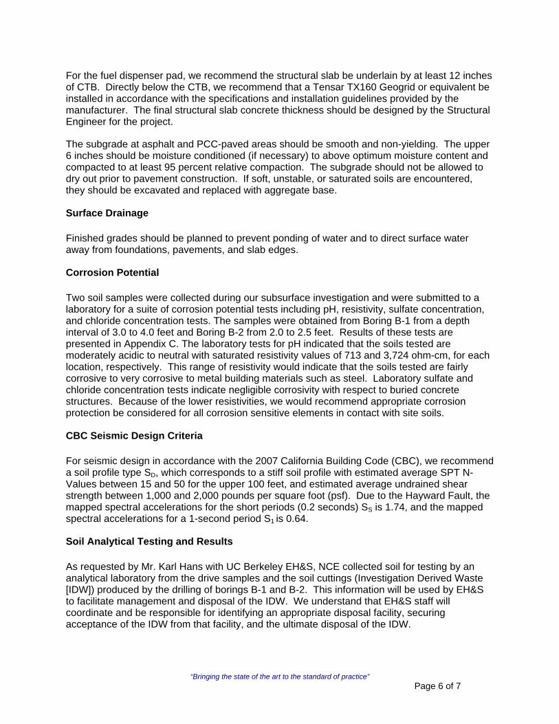
The proposed site for this fuel station is a mostly undeveloped parcel at the east side of the campus between Egret Way and S. 46th Street, just south of Plover Drive, as shown on the attached Site Plan. We understand that the planned fuel station will require site improvements in support of the following planned facility features:
Portland Cement Concrete (PCC) pad for parked hydrogen fuel tube trailers (80,000 lb when fully loaded) Asphalt concrete (AC) access from S. 46th Street PCC supported fuel dispenser Light pole foundation and fuel dispenser pad Hydrogen gas line from PCC truck pad to fuel dispenser (by others) Electrical line for fuel dispenser and light pole Bollards for protection of fuel dispenser
FIELD INVESTIGATION
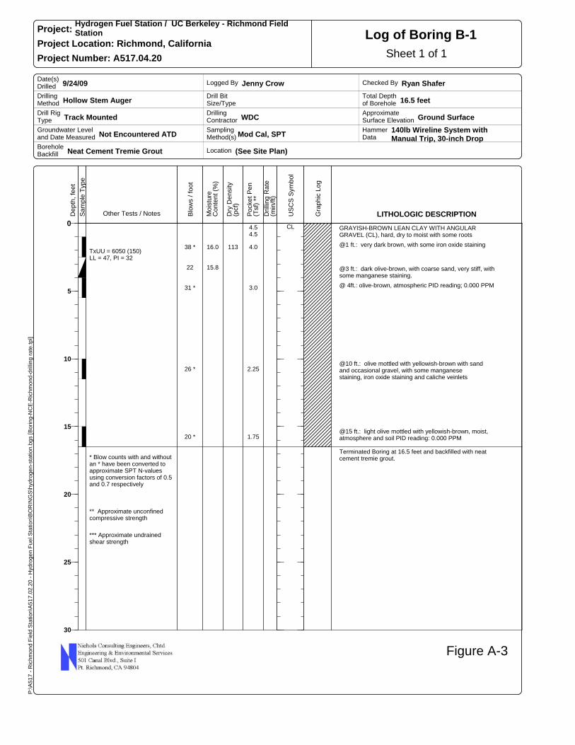
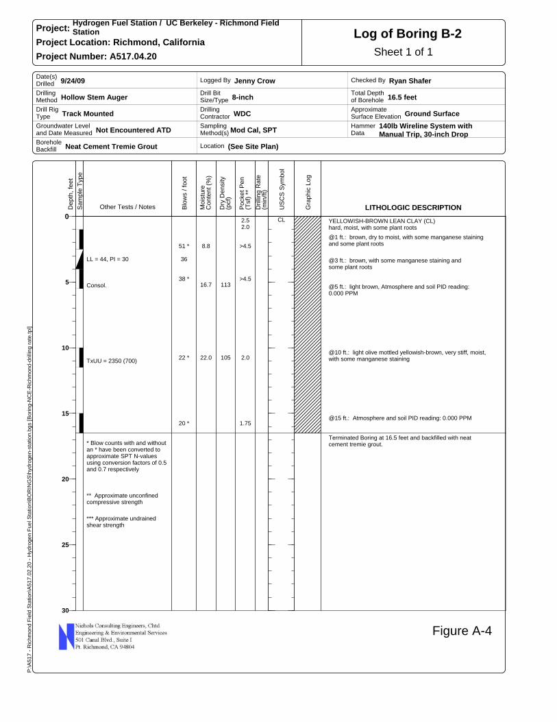
To provide geotechnical foundation recommendations in support of the planned facilities we performed a limited geotechnical investigation at the site that included drilling two borings to a depth of 16.5 feet below existing grade as shown on Figure 1. We generally encountered very stiff to hard clays with varying amounts of sand and gravel contents. Organics and plant roots
“Bringing the state of the art to the standard of practice” Page 1 of 7
were found in both borings primarily in the upper 1 foot of soil, and occasionally small roots observed to an approximate depth of 3 feet. The log of soils encountered is shown on the boring logs B-1 and B-2 in Appendix A. Groundwater was not encountered during drilling, but could be shallower that depths explored during the rainy season. Water conditions were generally observed during or shortly after the time of exploration and may have not had time to achieve equilibrium. Fluctuations in the groundwater level may also occur due to variations in rainfall, subsurface soil layer characteristics, temperature and other factors not evident at the time the measurements were made.
We performed laboratory testing on select soil samples to determine select geotechnical engineering and physical properties, which are summarized on the attached boring logs and in Appendix B. We also performed analytical testing on select soils samples to provide initial waste profiling information of the Investigation Derived Waste (IDW) that was generated during the drilling of geotechnical borings at the site, as presented in Appendix C.
DISCUSSION AND CONCLUSIONS
From a geotechnical and foundation engineering standpoint, it is our opinion that the site is suitable for the proposed facilities. However, all of the conclusions and recommendations presented in this technical memorandum should be incorporated in the design and construction of the project to reduce the possibility of soil and foundation problems.
The main geotechnical concern is the potential for expansive clay (tendency to shrink and swell with changes in moisture content), such as the higher plasticity clay that was encountered in both borings. However, we judge that this concern can be mitigated with careful subgrade soil compaction at above optimum moisture contents at all areas. Higher plasticity clays may also be difficult to compact during site grading and subgrade preparation, and may result in a condition where subgrade is soft and yielding and readily pumps. To address this concern we have provided recommendations for thickening aggregate base thicknesses for AC pavement, using cement treated base (CTB) below PCC pads, and the use of geotextiles in pavement and pad sections as will be discussed further in the recommendations section of this memorandum. In addition, where higher plasticity clays are especially wet and yielding, additional over-excavation and/or use of geotextiles may be necessary to obtain stability and required compaction. This condition will be further worsened if earthwork and grading is performed when soils have become wet during winter rains. Finally, based on our understanding from UC Berkeley Environmental Health and Safety (EH&S), pyrite cinders have been found at locations within the Richmond Field Station soils, and might be encountered during grading and earthwork, and if encountered during construction should be coordinated directly with EH&S.
RECOMMENDATIONS AND FINDINGS
Earthwork and Site Preparation
Subgrade Preparation
Areas to receive slabs, pavements, flatwork or fills should be stripped of any debris, vegetation, and organic topsoil (where present). Subgrade soils exposed by stripping within areas to receive fill or exterior flatwork/slabs, should be scarified to a minimum depth of 6 inches, moisture conditioned to at or above Optimum Moisture Content and re-compacted in place to at
“Bringing the state of the art to the standard of practice” Page 2 of 7
least 90 percent Relative Compaction1. Soils exposed by over-excavation should be moisture conditioned to at or above Optimum Moisture Content and compacted in place to at least 90 percent Relative Compaction. Pavement subgrades should be compacted to at least 95 percent Relative Compaction. Depressions or voids created by the removal of existing pavements, slabs, or utilities should be excavated to expose firm soil and backfilled as described later in this section.
Footing Excavations
Footing excavations should be cleared of any loose soil or debris and kept moist before concrete placement. Water should not be allowed to accumulate in footing excavations.
Our field engineer should verify that the exposed surfaces within footing excavations are firm and unyielding prior to any placement of reinforcing steel or concrete. Our field engineer will recommend reworking or over-excavation and replacement of footing subgrades where they are not suitable to bear structural loads.
Fills and Backfills
Non-expansive or import fill should consist of soil that has a Liquid Limit of less than 40 and a Plasticity Index of less than 15 (as determined by ASTM D 4318-98), is free of organic material, and contains no rocks or clods larger than 4 inches in greatest dimension. On-site soils are moderately expansive and occasionally highly expansive and will likely not meet the Liquid Limit and Plasticity Index Criteria. Therefore onsite clay soils may not be used as non-expansive fill, but may be used as general fill provided they meet the other criteria. Moisture conditioning may be necessary to achieve compaction requirements. NCE should confirm the suitability of on-site soils or import material prior to their use as fill or backfill.
Import fill or on-site fill should be moisture conditioned to near Optimum Moisture Content and on-site clayey soil being used as fill should be moisture conditioned to above Optimum Moisture Content. Fill should be placed in uniform horizontal layers not exceeding 8 inches in loose thickness, and compacted to at least 90 percent Relative Compaction. In areas where fill or backfill will underlie flatwork/slabs, the upper 6 inches of fill should be kept moist until flatwork/slabs are placed. Our field engineer or representative should monitor all placement and compaction of fill.
Utility Trenches
All utility trenches should be excavated in accordance with current OSHA excavation and trench safety standards. The contractor should be solely responsible for the design and construction of all excavation and trench safety.
We recommend that utility line bedding material consist of sand with less than 10 percent fines. The bedding should extend from the bottom of the trench to 1 foot above the top of the pipe. Sand bedding should be placed in a trench free of standing water and mechanically compacted to a dense condition (as verified by our field engineer).
1 Relative compaction refers to the in-place dry density of soil expressed as a percentage of the maximum dry density of the same soil determined by ASTM D1557 laboratory test procedure. Optimum Moisture Content is the water content that corresponds to the maximum dry density as determined by the same procedure.
“Bringing the state of the art to the standard of practice” Page 3 of 7
Trench backfill above the pipe bedding should meet the criteria for fill as described above. We should evaluate any proposed imported soil sample prior to its use as trench backfill. Trench backfill should be placed in uniform layers not exceeding 6 inches in loose thickness, moisture-conditioned to near-optimum moisture content, and compacted. Backfill should be compacted to at least 90 percent relative compaction, except for the upper 6 inches below pavement subgrade, which should be compacted to at least 95 percent relative compaction. Jetting should not be permitted for any backfill compaction.
Any water in utility trenches should be pumped out prior to backfilling.
Trenches near footings should not extend down below a 2:1 plane extending down and away from the bottom edge of any footing.
Foundation Support
If perimeter strip footings are required for support of the fuel dispenser pad, we recommend that the proposed facilities be supported on continuous strip footings bearing on undisturbed native soils.
In general, all footings should be founded at least 18 inches below the lowest adjacent finished grade. Footings located near other footings or utility trenches should have their bearing surfaces situated below an imaginary 1.5 horizontal to 1 vertical plane projected upward from the bottom of the nearby footing or utility trench.
At the above depths, the footings may be designed for an allowable bearing pressure of 2,800 pounds per square foot (psf) due to dead loads, 3,400 psf due to dead plus live loads and 4,200 psf for all loads including wind or seismic. The bearing values for dead load, dead plus live load, and all loads include a safety factor of approximately 3, 2.5 and 2, respectively. These allowable bearing pressures are net values; therefore, the weight of the footing can be neglected for design purposes. Footings should not, however, have a width of less than 18 inches.
All continuous footings should be designed with adequate top and bottom reinforcement to provide structural continuity and to permit spanning of local irregularities. Any visible cracks in the bottoms of the footing excavations should be closed by wetting prior to construction of the foundations. To assure that footings are founded on appropriate material, we recommend that we observe the footing excavations prior to placing steel or concrete.
Since the fuel dispenser pad is expected to be lightly loaded (less than 1000 psf), footing settlements are expected to be less than one inch. Differential settlements between adjacent footings should not exceed one-half of the total settlement, or approximately one-half inch, during the design lifetimes of the planned structures.
Lateral Load Resistance
Lateral load resistance for the buildings and retaining walls may be developed in friction between the foundation bottom and the supporting subgrade. A friction coefficient of 0.35 is considered applicable. In addition, a passive resistance equal to an equivalent fluid weighing 375 pounds per cubic foot acting against the foundations may be used. The above values for friction and passive resistance do not contain a safety factor. We typically recommend geotechnical safety factors of at least 2 for long-term and 1.5 for short term loads. The upper 12 inches of
“Bringing the state of the art to the standard of practice” Page 4 of 7
embedment can be ignored for passive resistance calculations except where the ground is paved or covered by a slab. Passive and friction resistance can be assumed to act together at the same time.
Flatwork and Slab-on-Grade Floors
Prior to constructing concrete slabs, pads, and other flatwork the subgrade should be prepared in accordance with the previous section on Subgrade Preparation. Due to the moderately expansive nature of some of the surface soil, we recommend that slab-on-grade floors and flatwork be supported on a minimum of 12 inches of imported non-expansive compacted fill. Prior to placement of the non-expansive fill, the subgrade surface should be scarified, moisture conditioned, and compacted to at least 90 percent Relative Compaction. In addition, all visible cracks should be closed by soaking prior to placement of non-expansive fill.
Slab reinforcing should be provided in accordance with the anticipated use and loading of the slab. Structural requirements and/or concentrated loads will require additional reinforcing. Minor movement of the concrete slab with resulting cracking should be expected. The recommendations presented above, if property implemented, should help reduce the magnitude of the cracking.
In areas where floor wetness would be undesirable, 4 inches of free draining gravel should be placed beneath the floor slab to serve as a capillary barrier between the subgrade soil and the slab. In order to minimize vapor transmission, an impermeable membrane should be placed over the gravel. The membrane should be covered with 2 inches of sand to protect it during construction. The sand should be lightly moistened just prior to placing the concrete. If used, the sand, membrane, and gravel may be considered to count as 6 inches of the recommended compacted, non-expansive, import fill.
Pavements
The asphalt concrete pavement improvements to access the fuel dispenser and truck trailer storage pads design section, as calculated per the Caltrans Highway Design Manual, is 4 inches of asphalt concrete (AC) over 7.5 inches of aggregate base (AB) based on a subgrade R-value of 5 and a TI of 5. The subgrade R-value and design TI are based on our previous pavement design experience on the Campus at Jay Way. However, we recommend an additional 6.5 inches of AB in expectation of difficult subgrade conditions, for a total of 14 inches of AB below the 4 inches of AC. To further address the difficult subgrade, we recommend that a Tensar TX160 Geogrid or equivalent be installed below the bottom of the AB layer and eight inches above the bottom of the AB layer in accordance with the specifications and installation guidelines provided by the manufacturer. In addition to placement of geogrid, there may be areas of yielding subgrade that may need to be additionally addressed with a combination of over-excavation of the yielding soils and replacement with aggregate base or crushed rock and the use of supplemental stabilizing geogrids.
For the truck trailer fuel storage pad, we recommend a 9-inch section of Portland concrete cement (PCC) over at least 12 inches of cement treated base (CTB). Directly below the CTB, we recommend that a Tensar TX160 Geogrid or equivalent be installed in accordance with the specifications and installation guidelines provided by the manufacturer. This pavement section recommendation is based on a subgrade R-value of 5 and a design TI of less than 9, per the Caltrans Highway Design Manual.
“Bringing the state of the art to the standard of practice” Page 5 of 7
For the fuel dispenser pad, we recommend the structural slab be underlain by at least 12 inches of CTB. Directly below the CTB, we recommend that a Tensar TX160 Geogrid or equivalent be installed in accordance with the specifications and installation guidelines provided by the manufacturer. The final structural slab concrete thickness should be designed by the Structural Engineer for the project.
The subgrade at asphalt and PCC-paved areas should be smooth and non-yielding. The upper 6 inches should be moisture conditioned (if necessary) to above optimum moisture content and compacted to at least 95 percent relative compaction. The subgrade should not be allowed to dry out prior to pavement construction. If soft, unstable, or saturated soils are encountered, they should be excavated and replaced with aggregate base.
Surface Drainage
Finished grades should be planned to prevent ponding of water and to direct surface water away from foundations, pavements, and slab edges.
Corrosion Potential
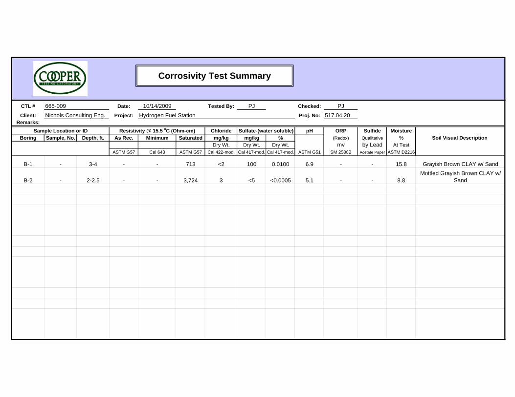
Two soil samples were collected during our subsurface investigation and were submitted to a laboratory for a suite of corrosion potential tests including pH, resistivity, sulfate concentration, and chloride concentration tests. The samples were obtained from Boring B-1 from a depth interval of 3.0 to 4.0 feet and Boring B-2 from 2.0 to 2.5 feet. Results of these tests are presented in Appendix C. The laboratory tests for pH indicated that the soils tested are moderately acidic to neutral with saturated resistivity values of 713 and 3,724 ohm-cm, for each location, respectively. This range of resistivity would indicate that the soils tested are fairly corrosive to very corrosive to metal building materials such as steel. Laboratory sulfate and chloride concentration tests indicate negligible corrosivity with respect to buried concrete structures. Because of the lower resistivities, we would recommend appropriate corrosion protection be considered for all corrosion sensitive elements in contact with site soils.
CBC Seismic Design Criteria
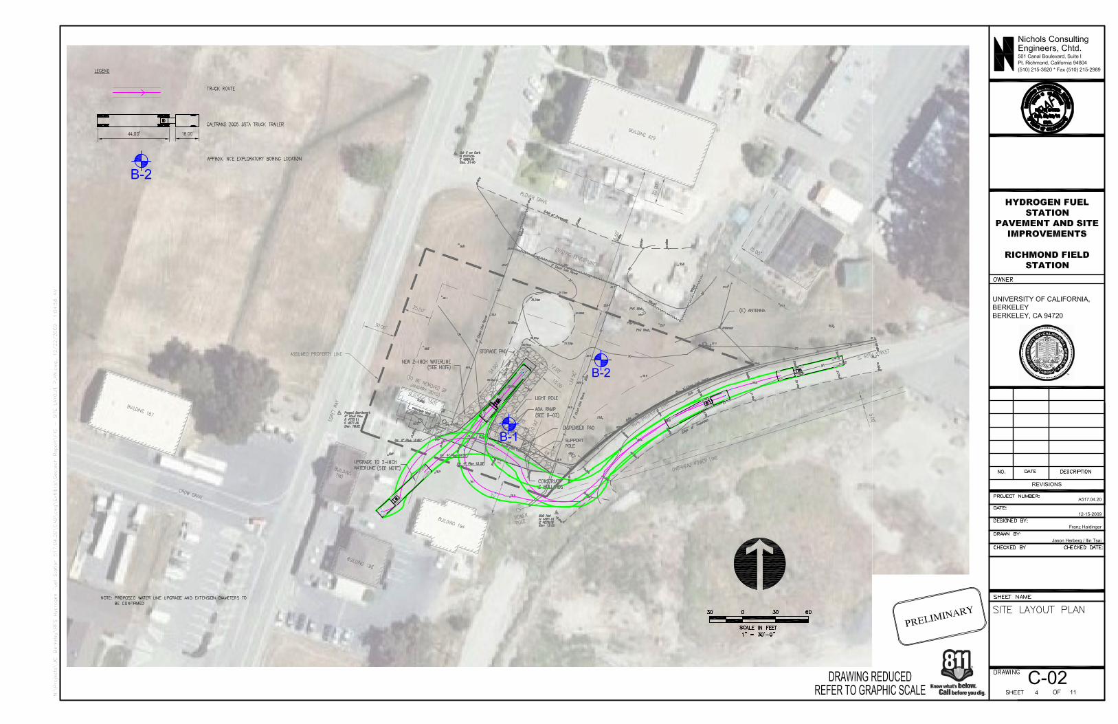
For seismic design in accordance with the 2007 California Building Code (CBC), we recommend a soil profile type SD, which corresponds to a stiff soil profile with estimated average SPT N-Values between 15 and 50 for the upper 100 feet, and estimated average undrained shear strength between 1,000 and 2,000 pounds per square foot (psf). Due to the Hayward Fault, the mapped spectral accelerations for the short periods (0.2 seconds) SS is 1.74, and the mapped spectral accelerations for a 1-second period S1 is 0.64.
Soil Analytical Testing and Results
As requested by Mr. Karl Hans with UC Berkeley EH&S, NCE collected soil for testing by an analytical laboratory from the drive samples and the soil cuttings (Investigation Derived Waste [IDW]) produced by the drilling of borings B-1 and B-2. This information will be used by EH&S to facilitate management and disposal of the IDW. We understand that EH&S staff will coordinate and be responsible for identifying an appropriate disposal facility, securing acceptance of the IDW from that facility, and the ultimate disposal of the IDW.
“Bringing the state of the art to the standard of practice” Page 6 of 7
“Bringing the state of the art to the standard of practice” Page 7 of 7
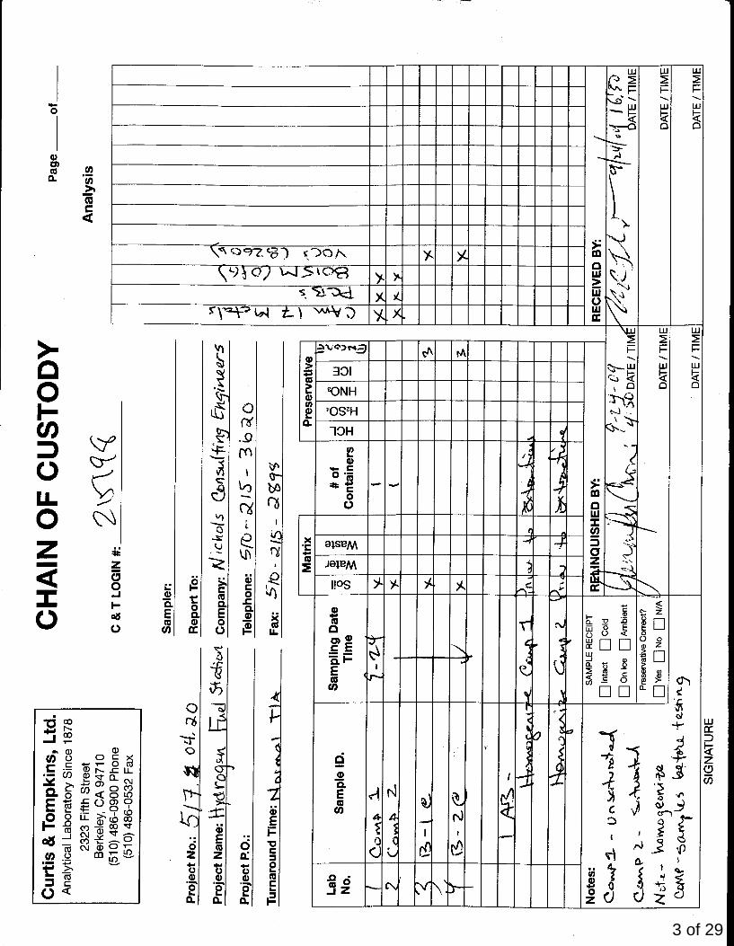
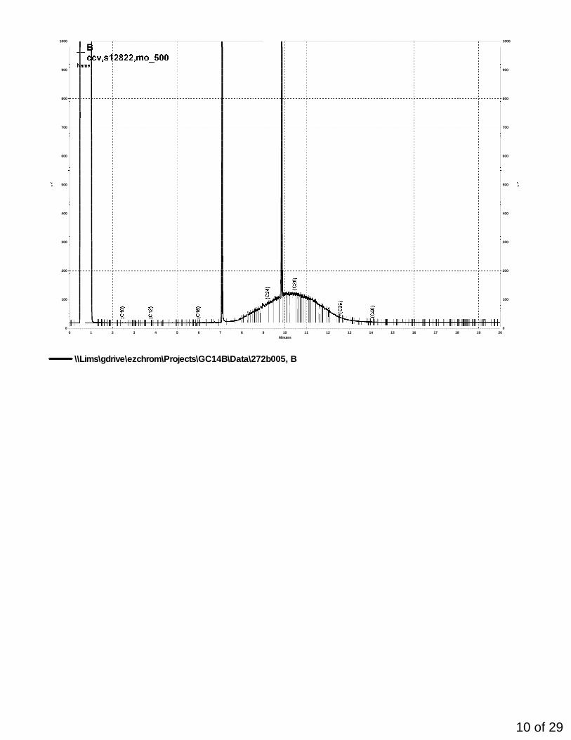
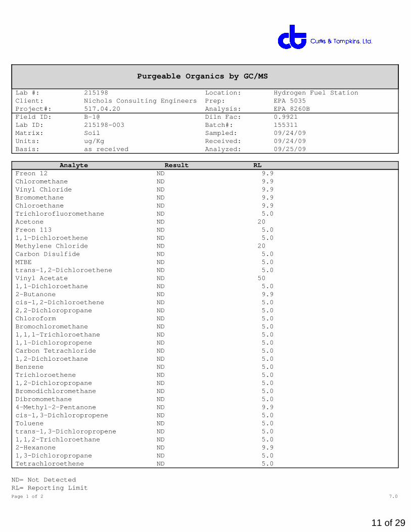
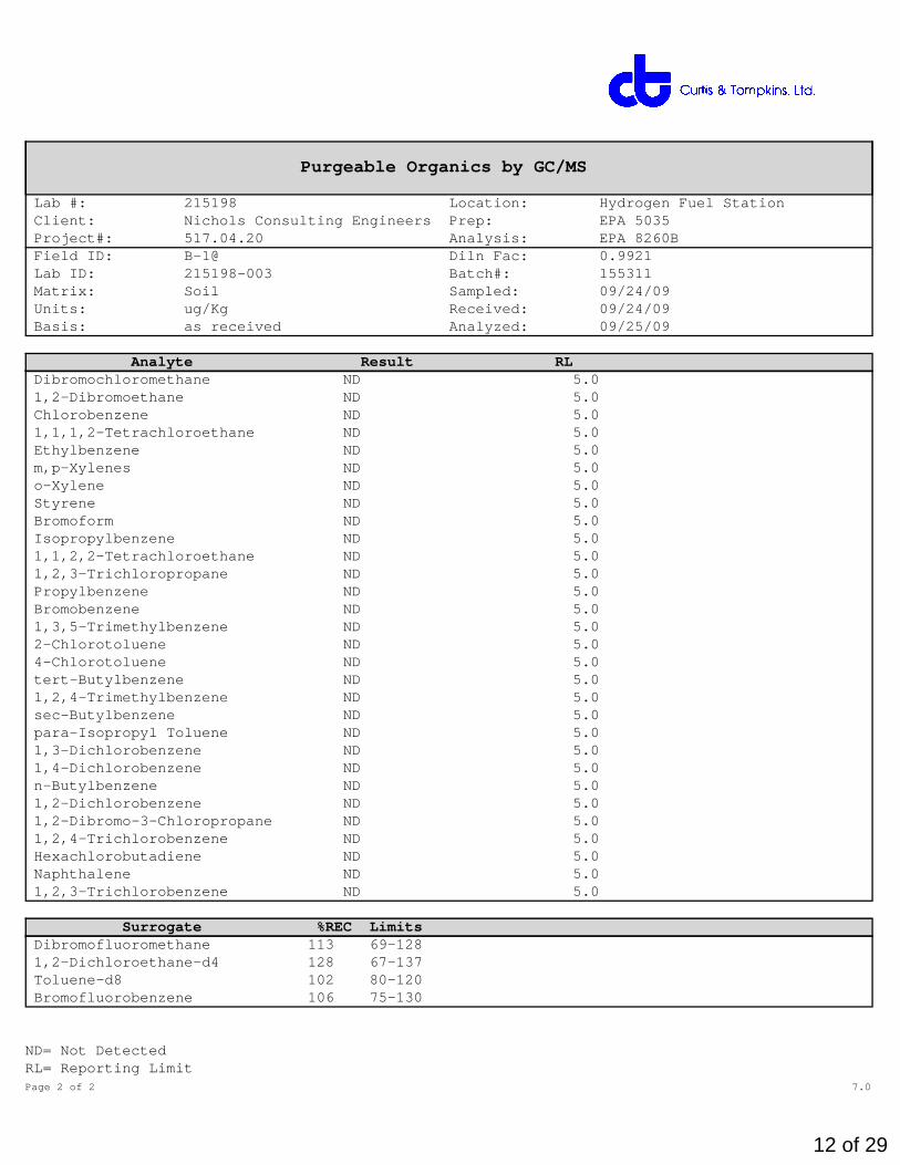
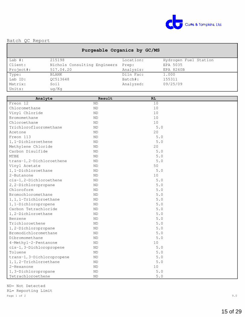
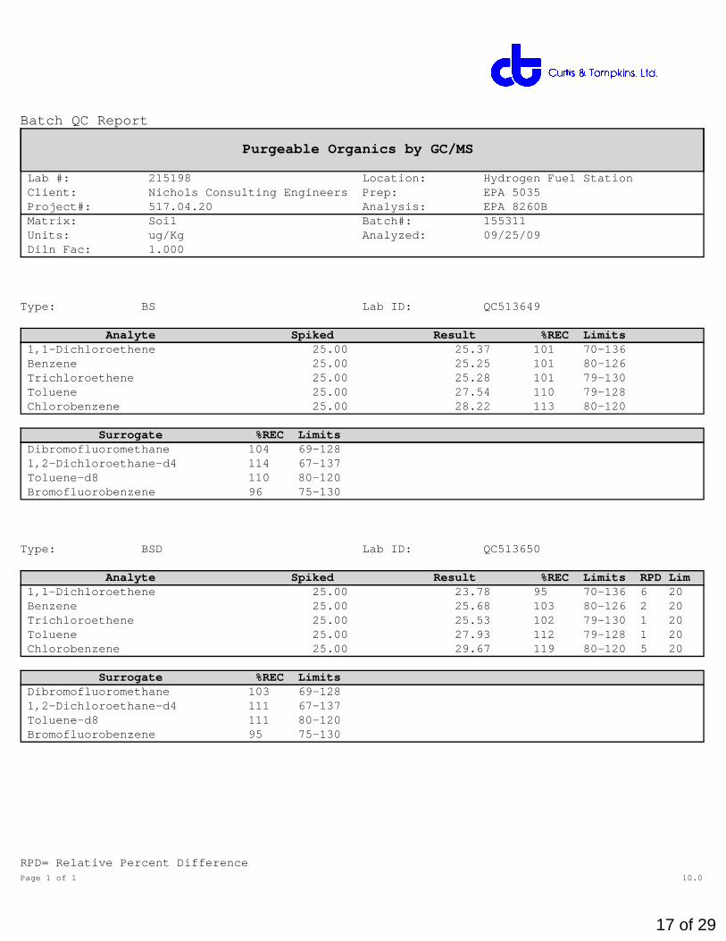
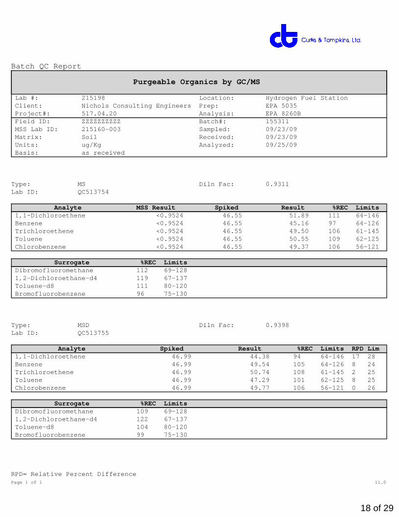
Two representative composite soil samples (one from each boring) were prepared from soils encountered from 0 to 10 feet bgs in the unsaturated zone. Soil collected between this interval was homogenized in a stainless steel mixing bowl to prepare the composite sample. Samples were submitted to Curtis & Thompkins laboratory in Berkeley, California. One composite sample from each boring was submitted and tested for polychlorinated biphenyls (PCBs), CAM17 Metals and total extractable hydrocarbons (TEH). In addition, one discrete soil sample was taken at approximately 10 feet bgs in each boring, from soil near the capillary fringe and tested for volatile organic compounds (VOCs). Soil cuttings from drilling activities were placed in 55-gallon drums and separated by depth: 0 to 10 feet for unsaturated soils and 10 to 15 feet for potentially saturated soils.
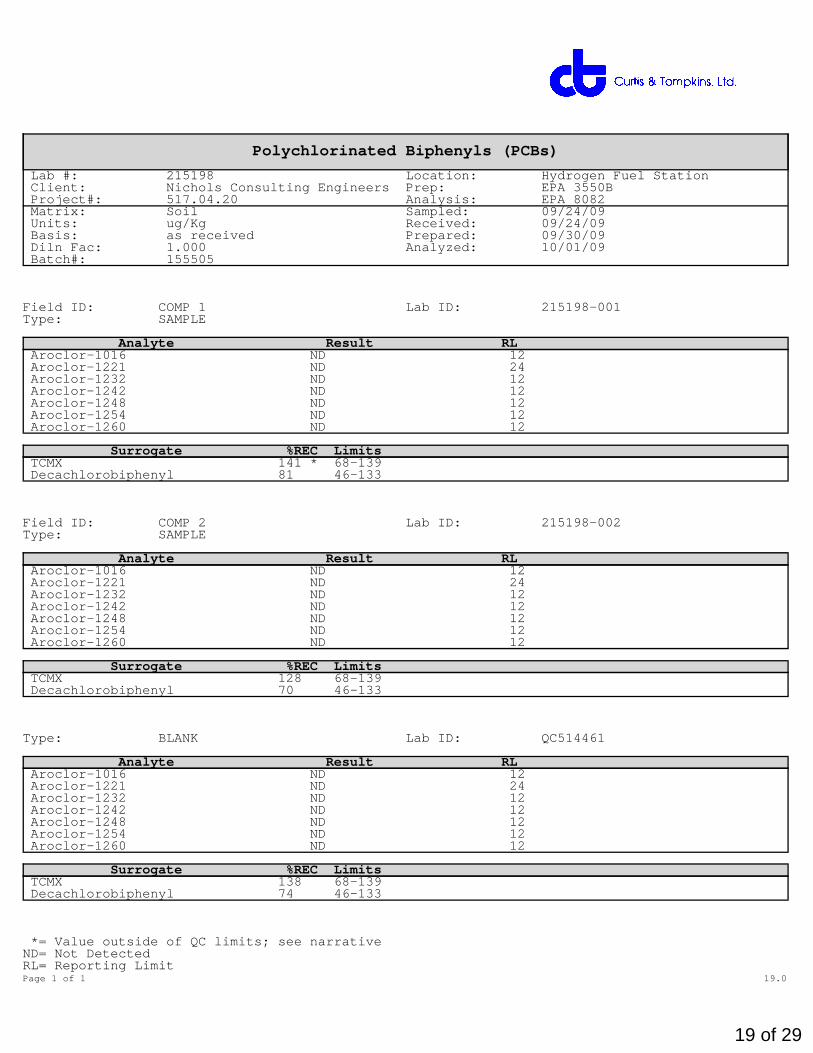
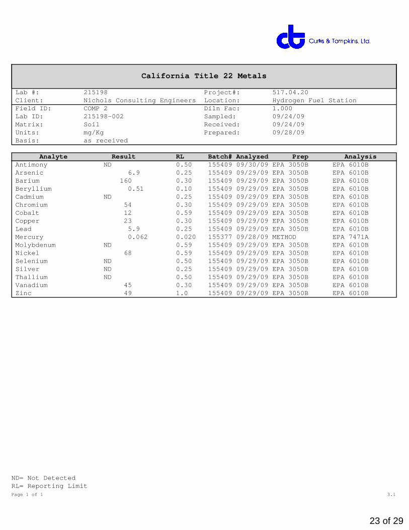
In summary, the testing found that the concentration of metals are low and suspected to be in a background range, while no VOCs or PCBs were found in any of the samples submitted. The laboratory reported low concentrations (levels near the method reporting limit of 5.0 milligrams per kilogram) of TEH in sample COMP 1 (composite sample from the upper 10 feet in Boring B-1). No TEH was reported from the sample submitted from Boring B-2. The laboratory reports and chain-of-custody forms are included in Appendix D.
SITE PLAN
APPENDIX A – BORING LOGS
P:\
A5
17
- R
ich
mo
nd
Fie
ld S
tatio
n\A
51
7.0
2.2
0 -
Hyd
roge
n F
uel S
tatio
n\B
OR
ING
S\h
ydro
gen-
stat
ion.
bgs
[Bor
ing-
NC
E-R
ichm
ond-
drill
ing
rate
.tpl
]
Figure A-3
Sheet 1 of 1
Project: Hydrogen Fuel Station / UC Berkeley - Richmond Field Station
Project Location: Richmond, California
Project Number: A517.04.20
Log of Boring B-1
Date(s) Drilled 9/24/09
Drilling Method Hollow Stem Auger
Drill Rig Type Track Mounted
Groundwater Level and Date Measured Not Encountered ATD
Borehole Backfill Neat Cement Tremie Grout
Logged By Jenny Crow
Drill Bit Size/Type
Drilling Contractor WDC
Sampling Method(s) Mod Cal, SPT
Location (See Site Plan)
Checked By Ryan Shafer
Total Depth of Borehole 16.5 feet
Approximate Surface Elevation Ground Surface
Hammer Data
140lb Wireline System with Manual Trip, 30-inch Drop
0
5
10
15
20
25
30
Dep
th,
feet
Sam
ple
Typ
e
Other Tests / Notes Blo
ws
/ fo
ot
Moi
stur
eC
onte
nt (
%)
Dry
De
nsi
ty(p
cf)
Poc
ket
Pen
(Tsf
) **
Dril
ling
Rat
e(m
in/f
t)
US
CS
Sym
bol
Gra
phic
Log
LITHOLOGIC DESCRIPTION
CL GRAYISH-BROWN LEAN CLAY WITH ANGULAR GRAVEL (CL), hard, dry to moist with some roots
@1 ft.: very dark brown, with some iron oxide staining
@3 ft.: dark olive-brown, with coarse sand, very stiff, with some manganese staining.
665-009Nichols Consulting EngineersHydrogen Fuel Station - 517.04.20
0.0
4.0
8.0
0.0 4.0 8.0 12.0 16.0Total Normal Stress, ksf
Sh
ear
Str
ess,
ksf
Stress-Strain Curves
0.00
2.00
4.00
6.00
8.00
10.00
12.00
14.00
0.0 5.0 10.0 15.0 20.0
Strain, %
De
via
tor
Str
es
s,
ks
f
Sample 1
Sample 2
Sample 3
Sample 4
Unconsolidated-Undrained Triaxial TestASTM D-2850
Project:
Remarks:Client:Project No.
%<#200%<#40PIPLLLMATERIAL DESCRIPTION
LIQUID AND PLASTIC LIMITS TEST REPORT
Source: B-1 Elev./Depth: 2-2.5'
Figure
LIQUID AND PLASTIC LIMITS TEST REPORT
COOPER TESTING LABORATORY
USCS
Nichols Consulting Engineers665-009
32.414.446.8Dark Brown Lean CLAY w/ Sand
Hydrogen Fuel Station - 517.04.20
Source: B-2 Elev./Depth: 3-4'
30.113.944.0Brown Sandy Lean CLAY
5 10 20 25 30 4035
39
43
47
51
55
NUMBER OF BLOWS
WA
TE
R C
ON
TE
NT
10 30 50 70 90 110LIQUID LIMIT
10
20
30
40
50
60P
LAS
TIC
ITY
IND
EX
47
CL-ML
CL or OL
CH or OH
ML or OL MH or OH
Dashed line indicates the approximateupper limit boundary for natural soils
APPENDIX C – ENVIRONMENTAL SAMPLING LABORATORY TEST RESULTS
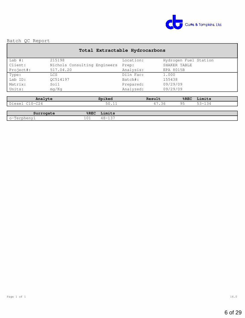
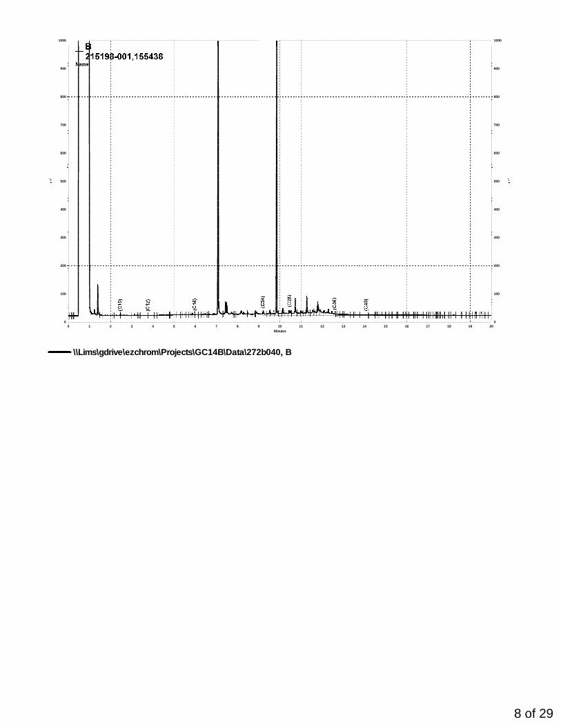
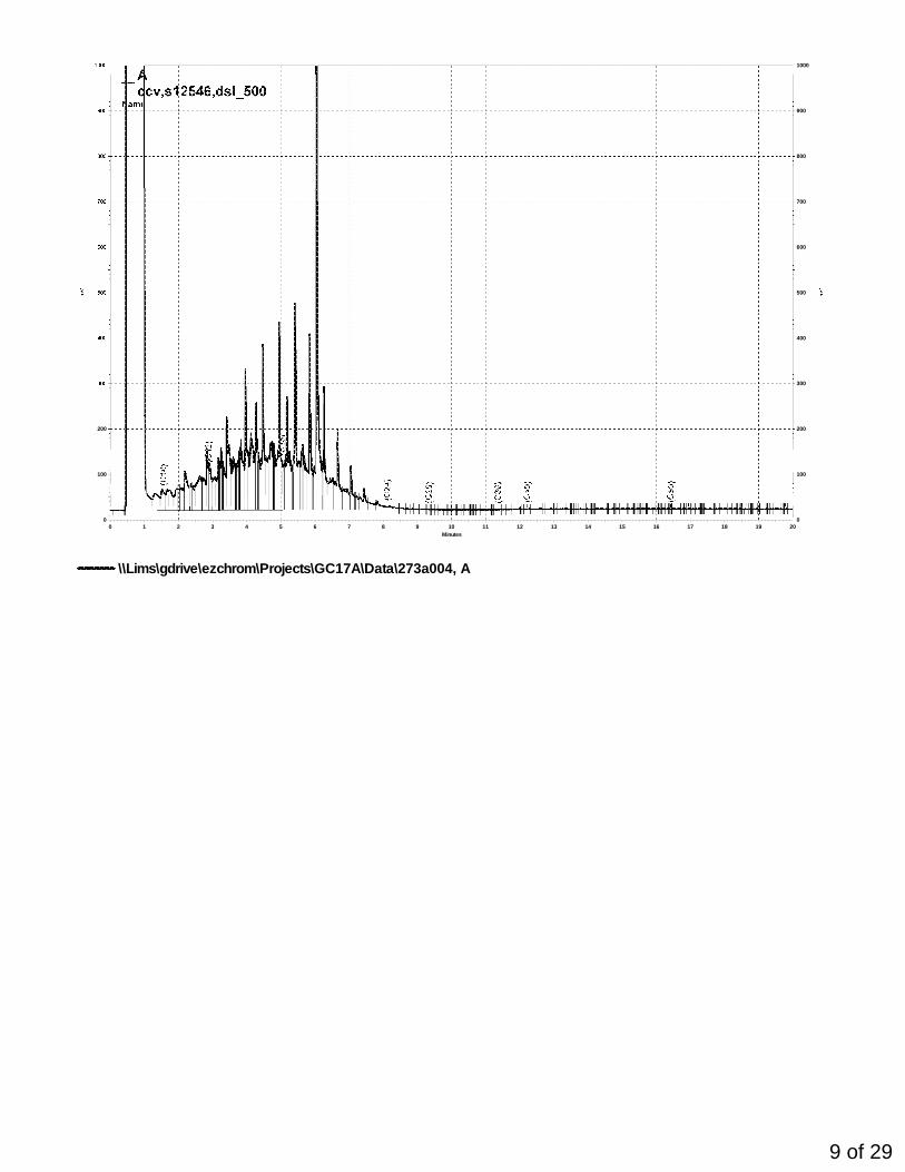
Laboratory Job Number 215198ANALYTICAL REPORT
Nichols Consulting Engineers Project : 517.04.20 501 Canal Blvd Location : Hydrogen Fuel Station Richmond, CA 94804 Level : II
Sample ID Lab IDCOMP 1 215198-001COMP 2 215198-002B-1@ 215198-003B-2@ 215198-004
This data package has been reviewed for technical correctness and completeness.Release of this data has been authorized by the Laboratory Manager or theManager's designee, as verified by the following signature. The resultscontained in this report meet all requirements of NELAC and pertain only tothose samples which were submitted for analysis. This report may be reproducedonly in its entirety.
This data package contains sample and QC results for four soil samples,requested for the above referenced project on 09/24/09. The samples werereceived cold and intact.
TPH-Extractables by GC (EPA 8015B):No analytical problems were encountered.
Volatile Organics by GC/MS (EPA 8260B):No analytical problems were encountered.
PCBs (EPA 8082):All samples underwent sulfuric acid cleanup using EPA Method 3665A. Allsamples underwent sulfur cleanup using the copper option in EPA Method 3660B.High surrogate recoveries were observed for TCMX in COMP 1 (lab # 215198-001)and the MS of COMP 1 (lab # 215198-001); the corresponding decachlorobiphenylsurrogate recoveries were within limits. No other analytical problems wereencountered.
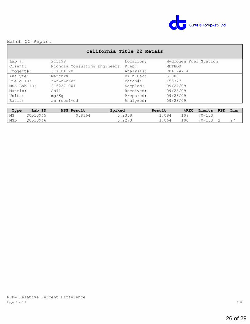
Metals (EPA 6010B and EPA 7471A):High recovery was observed for barium in the MSD for batch 155409; the parentsample was not a project sample, and the BS/BSD were within limits. High RPDwas also observed for barium in the MS/MSD for batch 155409; the RPD wasacceptable in the BS/BSD. No other analytical problems were encountered.