376
ENOVIA SmarTeam | Dassault Systémes www.3ds.com ENOVIA SmarTeam SmarTeam – Editor Administrator Guide

ENOVIA SmarTeam
SmarTeam – EditorAdministrator Guide
ENOVIA SmarTeam | Dassault Systémeswww.3ds.com

© Dassault Systèmes, 1997, 2011. All rights reserved.CATIA, ENOVIA, SMARTEAM and the 3DS logo are registered trademarks of Dassault Systèmes or its subsidiaries in the US and/or other countries. PROPRIETARY RIGHTS NOTICE: This documentation is the property of Dassault Systèmes. This documentation shall be treated as confidential information and may only be used by employees or contractors of the Customer in accordance with the terms of the End-User License Agreement accepted by Customer.Any use of the Licensed Program contained in this media or accompanying it, is subject to the terms of the End User License Agreement accepted by Customer. The Licensed Program is protected by international copyright laws and international treaties. Unauthorized use, reproduction and/or distribution of any of the Licensed Program, or any part thereof, may result in severe civil and/or criminal penalties, and will be prosecuted to the maximum extent possible under the law. Company names and product names mentioned herein are the property of their respective owners and certain portions of the Licensed Program contain elements subject to copyright owned by these entities. See the Documentation CD provided with the Licensed Program for details and/or additional terms and conditions relating to these entities.
Part Number: EDR-A4-220011

Contents
Contents
Contents . . . . . . . . . . . . . . . . . . . . . . . . . . . . . . . . . . . . . . . . . . . . . . . . . . . . . . . . . . . . . . . iSmarTeam Admin Console . . . . . . . . . . . . . . . . . . . . . . . . . . . . . . . . . . . . . . . . . . . . . . . . . . . . . . . . . . . . . . . . . 1
Accessing the Admin Console . . . . . . . . . . . . . . . . . . . . . . . . . . . . . . . . . . . . . . . . . . . . . . . . . . . . . . . . . . . . 2From within SmarTeam – Editor . . . . . . . . . . . . . . . . . . . . . . . . . . . . . . . . . . . . . . . . . . . . . . . . . . . . . . . 2External to SmarTeam – Editor . . . . . . . . . . . . . . . . . . . . . . . . . . . . . . . . . . . . . . . . . . . . . . . . . . . . . . . . . 2
Running a Tool from the Admin Console . . . . . . . . . . . . . . . . . . . . . . . . . . . . . . . . . . . . . . . . . . . . . . . . . . . 3Configuring the Admin Console Views . . . . . . . . . . . . . . . . . . . . . . . . . . . . . . . . . . . . . . . . . . . . . . . . . . . . . 3Closing the Admin Console . . . . . . . . . . . . . . . . . . . . . . . . . . . . . . . . . . . . . . . . . . . . . . . . . . . . . . . . . . . . . . 3Admin Console Tools List . . . . . . . . . . . . . . . . . . . . . . . . . . . . . . . . . . . . . . . . . . . . . . . . . . . . . . . . . . . . . . . 3
Application Tools . . . . . . . . . . . . . . . . . . . . . . . . . . . . . . . . . . . . . . . . . . . . . . . . . . . . . . . . . . . . . . . . . . . 3Security Management . . . . . . . . . . . . . . . . . . . . . . . . . . . . . . . . . . . . . . . . . . . . . . . . . . . . . . . . . . . . . . . . 4Workflow Management . . . . . . . . . . . . . . . . . . . . . . . . . . . . . . . . . . . . . . . . . . . . . . . . . . . . . . . . . . . . . . 5Vault Management . . . . . . . . . . . . . . . . . . . . . . . . . . . . . . . . . . . . . . . . . . . . . . . . . . . . . . . . . . . . . . . . . . 5User Interface Management . . . . . . . . . . . . . . . . . . . . . . . . . . . . . . . . . . . . . . . . . . . . . . . . . . . . . . . . . . . 6
Additional SmarTeam Administrative Tools . . . . . . . . . . . . . . . . . . . . . . . . . . . . . . . . . . . . . . . . . . . . . . . . . 6Customizing SmarTeam – Editor . . . . . . . . . . . . . . . . . . . . . . . . . . . . . . . . . . . . . . . . . . . . . . . . . . . . . . . . . . . . . 7Understanding SmarTeam – Editor Menus and Toolbars . . . . . . . . . . . . . . . . . . . . . . . . . . . . . . . . . . . . . . . . . . 7Menu Profiles . . . . . . . . . . . . . . . . . . . . . . . . . . . . . . . . . . . . . . . . . . . . . . . . . . . . . . . . . . . . . . . . . . . . . . . . . . . . 8
System Profiles Menu . . . . . . . . . . . . . . . . . . . . . . . . . . . . . . . . . . . . . . . . . . . . . . . . . . . . . . . . . . . . . . . . . . . 8User Profiles Menu . . . . . . . . . . . . . . . . . . . . . . . . . . . . . . . . . . . . . . . . . . . . . . . . . . . . . . . . . . . . . . . . . . . . . 9
Menu Commands . . . . . . . . . . . . . . . . . . . . . . . . . . . . . . . . . . . . . . . . . . . . . . . . . . . . . . . . . . . . . . . . . . . . . . . . . 9Standard Commands . . . . . . . . . . . . . . . . . . . . . . . . . . . . . . . . . . . . . . . . . . . . . . . . . . . . . . . . . . . . . . . . . . . . 9User-defined Commands (scripts) . . . . . . . . . . . . . . . . . . . . . . . . . . . . . . . . . . . . . . . . . . . . . . . . . . . . . . . . . 9Custom commands (currently not available in this version) . . . . . . . . . . . . . . . . . . . . . . . . . . . . . . . . . . . . . 9
Menu Contexts . . . . . . . . . . . . . . . . . . . . . . . . . . . . . . . . . . . . . . . . . . . . . . . . . . . . . . . . . . . . . . . . . . . . . . . . . . . 9Effects of Changes in the Administrative Tools . . . . . . . . . . . . . . . . . . . . . . . . . . . . . . . . . . . . . . . . . . . . . . . . . 10
Changes to be Made Only when Setting Up the Environment . . . . . . . . . . . . . . . . . . . . . . . . . . . . . . . . . . . 10Changes That Require User Relogin . . . . . . . . . . . . . . . . . . . . . . . . . . . . . . . . . . . . . . . . . . . . . . . . . . . . . . 10Changes That Do Not Require User Relogin . . . . . . . . . . . . . . . . . . . . . . . . . . . . . . . . . . . . . . . . . . . . . . . . 11
Vault Server Details Window . . . . . . . . . . . . . . . . . . . . . . . . . . . . . . . . . . . . . . . . . . . . . . . . . . . . . . . . . . . . . . . 12Shared Directory Details Window . . . . . . . . . . . . . . . . . . . . . . . . . . . . . . . . . . . . . . . . . . . . . . . . . . . . . . . . 13Vault Browser Window . . . . . . . . . . . . . . . . . . . . . . . . . . . . . . . . . . . . . . . . . . . . . . . . . . . . . . . . . . . . . . . . 14Vault Details Window . . . . . . . . . . . . . . . . . . . . . . . . . . . . . . . . . . . . . . . . . . . . . . . . . . . . . . . . . . . . . . . . . 14Vault Data Window . . . . . . . . . . . . . . . . . . . . . . . . . . . . . . . . . . . . . . . . . . . . . . . . . . . . . . . . . . . . . . . . . . . 15Vault Maintenance . . . . . . . . . . . . . . . . . . . . . . . . . . . . . . . . . . . . . . . . . . . . . . . . . . . . . . . . . . . . . . . . . . . . 15Running the Vault Default Utility . . . . . . . . . . . . . . . . . . . . . . . . . . . . . . . . . . . . . . . . . . . . . . . . . . . . . . . . 15Changing Vault Service Parameters . . . . . . . . . . . . . . . . . . . . . . . . . . . . . . . . . . . . . . . . . . . . . . . . . . . . . . . 16
Lookup Tables . . . . . . . . . . . . . . . . . . . . . . . . . . . . . . . . . . . . . . . . . . . . . . . . . . . . . . . . . . . . . . . . . . . . . . . . . . 18
SmarTeam – Editor Administrator Guide i
Contents
Creating a Lookup Field . . . . . . . . . . . . . . . . . . . . . . . . . . . . . . . . . . . . . . . . . . . . . . . . . . . . . . . . . . . . . . . . 18Adding a Lookup Field in the Working Form . . . . . . . . . . . . . . . . . . . . . . . . . . . . . . . . . . . . . . . . . . . . . . . 18
User Maintenance . . . . . . . . . . . . . . . . . . . . . . . . . . . . . . . . . . . . . . . . . . . . . . . . . . . . . . . . . . . . . . . . . . . . . . . . 19Defining Users . . . . . . . . . . . . . . . . . . . . . . . . . . . . . . . . . . . . . . . . . . . . . . . . . . . . . . . . . . . . . . . . . . . . . . . 20
Copying a User’s Groups and Roles to Another User . . . . . . . . . . . . . . . . . . . . . . . . . . . . . . . . . . . . . . 22Assigning a User to Groups and Roles . . . . . . . . . . . . . . . . . . . . . . . . . . . . . . . . . . . . . . . . . . . . . . . . . . 23
When to Create a Group and When a Role . . . . . . . . . . . . . . . . . . . . . . . . . . . . . . . . . . . . . . . . . . . . . . . . . . 24Defining Groups and Roles . . . . . . . . . . . . . . . . . . . . . . . . . . . . . . . . . . . . . . . . . . . . . . . . . . . . . . . . . . . . . . 24
Defining Groups . . . . . . . . . . . . . . . . . . . . . . . . . . . . . . . . . . . . . . . . . . . . . . . . . . . . . . . . . . . . . . . . . . . 24Defining Roles . . . . . . . . . . . . . . . . . . . . . . . . . . . . . . . . . . . . . . . . . . . . . . . . . . . . . . . . . . . . . . . . . . . . 25
Define User Passwords . . . . . . . . . . . . . . . . . . . . . . . . . . . . . . . . . . . . . . . . . . . . . . . . . . . . . . . . . . . . . . . . . 26Password Rules . . . . . . . . . . . . . . . . . . . . . . . . . . . . . . . . . . . . . . . . . . . . . . . . . . . . . . . . . . . . . . . . . . . . 26Changing Passwords . . . . . . . . . . . . . . . . . . . . . . . . . . . . . . . . . . . . . . . . . . . . . . . . . . . . . . . . . . . . . . . . 27
Assigning Authorizations . . . . . . . . . . . . . . . . . . . . . . . . . . . . . . . . . . . . . . . . . . . . . . . . . . . . . . . . . . . . . . . 27Table of Operations in the User Authorization Screen . . . . . . . . . . . . . . . . . . . . . . . . . . . . . . . . . . . . . . 29
Authorizations . . . . . . . . . . . . . . . . . . . . . . . . . . . . . . . . . . . . . . . . . . . . . . . . . . . . . . . . . . . . . . . . . . . . . . . . . . 34Global Authorizations . . . . . . . . . . . . . . . . . . . . . . . . . . . . . . . . . . . . . . . . . . . . . . . . . . . . . . . . . . . . . . . . . . 34Project-based Authorizations . . . . . . . . . . . . . . . . . . . . . . . . . . . . . . . . . . . . . . . . . . . . . . . . . . . . . . . . . . . . 34
Users, Objects and Projects Relationship . . . . . . . . . . . . . . . . . . . . . . . . . . . . . . . . . . . . . . . . . . . . . . . . 35Examples . . . . . . . . . . . . . . . . . . . . . . . . . . . . . . . . . . . . . . . . . . . . . . . . . . . . . . . . . . . . . . . . . . . . . . . . . 36
Example 1 36Example 2 37
Users Object Authorizations Flowchart . . . . . . . . . . . . . . . . . . . . . . . . . . . . . . . . . . . . . . . . . . . . . . . . . 38Setting Up and Enabling Project-Based Authorizations . . . . . . . . . . . . . . . . . . . . . . . . . . . . . . . . . . . . . . . . 38Setting Project-based Authorizations - User . . . . . . . . . . . . . . . . . . . . . . . . . . . . . . . . . . . . . . . . . . . . . . . . . 40
Associating Objects to a Project . . . . . . . . . . . . . . . . . . . . . . . . . . . . . . . . . . . . . . . . . . . . . . . . . . . . . . . 40Setting Project Authorization Properties . . . . . . . . . . . . . . . . . . . . . . . . . . . . . . . . . . . . . . . . . . . . . . . . . 41
Adding the User Authorization Report Utility Option . . . . . . . . . . . . . . . . . . . . . . . . . . . . . . . . . . . . . . . . . 44Viewing the Object Authorization Report . . . . . . . . . . . . . . . . . . . . . . . . . . . . . . . . . . . . . . . . . . . . . . . . . . 44
Object Authorization Details Window . . . . . . . . . . . . . . . . . . . . . . . . . . . . . . . . . . . . . . . . . . . . . . . . . . 45Menu Editor . . . . . . . . . . . . . . . . . . . . . . . . . . . . . . . . . . . . . . . . . . . . . . . . . . . . . . . . . . . . . . . . . . . . . . . . . . . . 46
Working with the Menu Editor . . . . . . . . . . . . . . . . . . . . . . . . . . . . . . . . . . . . . . . . . . . . . . . . . . . . . . . . . . . 46Launching the Menu Editor . . . . . . . . . . . . . . . . . . . . . . . . . . . . . . . . . . . . . . . . . . . . . . . . . . . . . . . . . . . . . 47
Adding a New Product . . . . . . . . . . . . . . . . . . . . . . . . . . . . . . . . . . . . . . . . . . . . . . . . . . . . . . . . . . . . . . 47Customizing the SmarTeam – Editor Main Menu . . . . . . . . . . . . . . . . . . . . . . . . . . . . . . . . . . . . . . . . . . . . 48
Adding a New System Profile . . . . . . . . . . . . . . . . . . . . . . . . . . . . . . . . . . . . . . . . . . . . . . . . . . . . . . . . . 49Profile Groups Window . . . . . . . . . . . . . . . . . . . . . . . . . . . . . . . . . . . . . . . . . . . . . . . . . . . . . . . . . . . . . 51
Adding a User’s Group to the Menu Profile . . . . . . . . . . . . . . . . . . . . . . . . . . . . . . . . . . . . . . . . . . . . . . . . . 51Toolbar Manager Window . . . . . . . . . . . . . . . . . . . . . . . . . . . . . . . . . . . . . . . . . . . . . . . . . . . . . . . . . . . . . . 51
Toolbars . . . . . . . . . . . . . . . . . . . . . . . . . . . . . . . . . . . . . . . . . . . . . . . . . . . . . . . . . . . . . . . . . . . . . . . . . . 51Options . . . . . . . . . . . . . . . . . . . . . . . . . . . . . . . . . . . . . . . . . . . . . . . . . . . . . . . . . . . . . . . . . . . . . . . . . . 51
Toolbar Area . . . . . . . . . . . . . . . . . . . . . . . . . . . . . . . . . . . . . . . . . . . . . . . . . . . . . . . . . . . . . . . . . . . . . . . . . 52Adding a Toolbar Area . . . . . . . . . . . . . . . . . . . . . . . . . . . . . . . . . . . . . . . . . . . . . . . . . . . . . . . . . . . . . . 53Editing a Toolbar Area . . . . . . . . . . . . . . . . . . . . . . . . . . . . . . . . . . . . . . . . . . . . . . . . . . . . . . . . . . . . . . 54Deleting a Toolbar Area . . . . . . . . . . . . . . . . . . . . . . . . . . . . . . . . . . . . . . . . . . . . . . . . . . . . . . . . . . . . . 54Linking a Toolbar to a Toolbar Area . . . . . . . . . . . . . . . . . . . . . . . . . . . . . . . . . . . . . . . . . . . . . . . . . . . 54
Deleting Menus/Toolbars . . . . . . . . . . . . . . . . . . . . . . . . . . . . . . . . . . . . . . . . . . . . . . . . . . . . . . . . . . . . . . . 55Deleting a Menu/Toolbar Command . . . . . . . . . . . . . . . . . . . . . . . . . . . . . . . . . . . . . . . . . . . . . . . . . . . . . . 56
SmarTeam – Editor Administrator Guide ii

Contents
Making a Menu/Toolbar Command Invisible . . . . . . . . . . . . . . . . . . . . . . . . . . . . . . . . . . . . . . . . . . . . . . . 56Adding a New Menu Item to a Sub-Menu . . . . . . . . . . . . . . . . . . . . . . . . . . . . . . . . . . . . . . . . . . . . . . . . . . 57Adding User-defined Commands . . . . . . . . . . . . . . . . . . . . . . . . . . . . . . . . . . . . . . . . . . . . . . . . . . . . . . . . . 59
Positive Contexts . . . . . . . . . . . . . . . . . . . . . . . . . . . . . . . . . . . . . . . . . . . . . . . . . . . . . . . . . . . . . . . . . . . 60Negative Contexts . . . . . . . . . . . . . . . . . . . . . . . . . . . . . . . . . . . . . . . . . . . . . . . . . . . . . . . . . . . . . . . . . . 60
Removing a Context 60Attaching an Icon to the Selected Command 60
Editing User-defined Commands . . . . . . . . . . . . . . . . . . . . . . . . . . . . . . . . . . . . . . . . . . . . . . . . . . . . . . 61Deleting User-defined Commands . . . . . . . . . . . . . . . . . . . . . . . . . . . . . . . . . . . . . . . . . . . . . . . . . . . . . 61
Saving in the Menu Editor . . . . . . . . . . . . . . . . . . . . . . . . . . . . . . . . . . . . . . . . . . . . . . . . . . . . . . . . . . . . . . 62Editing Existing System Profiles . . . . . . . . . . . . . . . . . . . . . . . . . . . . . . . . . . . . . . . . . . . . . . . . . . . . . . . . . 62Custom Contexts . . . . . . . . . . . . . . . . . . . . . . . . . . . . . . . . . . . . . . . . . . . . . . . . . . . . . . . . . . . . . . . . . . . . . . 63Merging Menu Profiles . . . . . . . . . . . . . . . . . . . . . . . . . . . . . . . . . . . . . . . . . . . . . . . . . . . . . . . . . . . . . . . . . 65Upgrading from Previous Versions . . . . . . . . . . . . . . . . . . . . . . . . . . . . . . . . . . . . . . . . . . . . . . . . . . . . . . . 66
Project Manager . . . . . . . . . . . . . . . . . . . . . . . . . . . . . . . . . . . . . . . . . . . . . . . . . . . . . . . . . . . . . . . . . . . . . . . . . 67Using the Project Manager . . . . . . . . . . . . . . . . . . . . . . . . . . . . . . . . . . . . . . . . . . . . . . . . . . . . . . . . . . . . . . 67Save Options Window . . . . . . . . . . . . . . . . . . . . . . . . . . . . . . . . . . . . . . . . . . . . . . . . . . . . . . . . . . . . . . . . . 69
Save Tab . . . . . . . . . . . . . . . . . . . . . . . . . . . . . . . . . . . . . . . . . . . . . . . . . . . . . . . . . . . . . . . . . . . . . . . . . 69Batch Save Mode 69Display the "Project Manager" Dialog for save 69
Tree Setting Tab . . . . . . . . . . . . . . . . . . . . . . . . . . . . . . . . . . . . . . . . . . . . . . . . . . . . . . . . . . . . . . . . . . . 69Expand Level of Project Tree 69Expand Level of Objects Tree 69
Configuring the Project Manager Window . . . . . . . . . . . . . . . . . . . . . . . . . . . . . . . . . . . . . . . . . . . . . . . . . . 69Default Values Utility . . . . . . . . . . . . . . . . . . . . . . . . . . . . . . . . . . . . . . . . . . . . . . . . . . . . . . . . . . . . . . . . . . . . . 70
Running the Default Values Utility . . . . . . . . . . . . . . . . . . . . . . . . . . . . . . . . . . . . . . . . . . . . . . . . . . . . . . . 70Defining a Default Value . . . . . . . . . . . . . . . . . . . . . . . . . . . . . . . . . . . . . . . . . . . . . . . . . . . . . . . . . . . . . . . 71Default Values Utility – Menu Options . . . . . . . . . . . . . . . . . . . . . . . . . . . . . . . . . . . . . . . . . . . . . . . . . . . . 71
File Menu . . . . . . . . . . . . . . . . . . . . . . . . . . . . . . . . . . . . . . . . . . . . . . . . . . . . . . . . . . . . . . . . . . . . . . . . 71Options Menu . . . . . . . . . . . . . . . . . . . . . . . . . . . . . . . . . . . . . . . . . . . . . . . . . . . . . . . . . . . . . . . . . . . . . 71
Default Values Utility - Toolbar . . . . . . . . . . . . . . . . . . . . . . . . . . . . . . . . . . . . . . . . . . . . . . . . . . . . . . . . . . 71Database Connection Manager . . . . . . . . . . . . . . . . . . . . . . . . . . . . . . . . . . . . . . . . . . . . . . . . . . . . . . . . . . . . . . 72
Launching the Database Connection Manager . . . . . . . . . . . . . . . . . . . . . . . . . . . . . . . . . . . . . . . . . . . . . . . 72Adding a Database Connection . . . . . . . . . . . . . . . . . . . . . . . . . . . . . . . . . . . . . . . . . . . . . . . . . . . . . . . . . . . 73Deleting a Database Connection . . . . . . . . . . . . . . . . . . . . . . . . . . . . . . . . . . . . . . . . . . . . . . . . . . . . . . . . . 74Working with Databases . . . . . . . . . . . . . . . . . . . . . . . . . . . . . . . . . . . . . . . . . . . . . . . . . . . . . . . . . . . . . . . . 74
ORACLE . . . . . . . . . . . . . . . . . . . . . . . . . . . . . . . . . . . . . . . . . . . . . . . . . . . . . . . . . . . . . . . . . . . . . . . . . 74DB2 Database . . . . . . . . . . . . . . . . . . . . . . . . . . . . . . . . . . . . . . . . . . . . . . . . . . . . . . . . . . . . . . . . . . . . . 75MS SQL or MSDE Database . . . . . . . . . . . . . . . . . . . . . . . . . . . . . . . . . . . . . . . . . . . . . . . . . . . . . . . . . 75
Attaching and Connecting to an MSDE Database File . . . . . . . . . . . . . . . . . . . . . . . . . . . . . . . . . . . . . . . . . 75Detaching an MSDE Database Connection . . . . . . . . . . . . . . . . . . . . . . . . . . . . . . . . . . . . . . . . . . . . . . . . . 76Database-specific Components . . . . . . . . . . . . . . . . . . . . . . . . . . . . . . . . . . . . . . . . . . . . . . . . . . . . . . . . . . . 77
ADO OLE DB Providers . . . . . . . . . . . . . . . . . . . . . . . . . . . . . . . . . . . . . . . . . . . . . . . . . . . . . . . . . . . . 77Troubleshooting . . . . . . . . . . . . . . . . . . . . . . . . . . . . . . . . . . . . . . . . . . . . . . . . . . . . . . . . . . . . . . . . . . . . . . 77
Integration Tools Setup . . . . . . . . . . . . . . . . . . . . . . . . . . . . . . . . . . . . . . . . . . . . . . . . . . . . . . . . . . . . . . . . . . . 78Terminology . . . . . . . . . . . . . . . . . . . . . . . . . . . . . . . . . . . . . . . . . . . . . . . . . . . . . . . . . . . . . . . . . . . . . . . . . 78Starting the Integration Tool Setup Utility . . . . . . . . . . . . . . . . . . . . . . . . . . . . . . . . . . . . . . . . . . . . . . . . . . 78Mapping Group Types . . . . . . . . . . . . . . . . . . . . . . . . . . . . . . . . . . . . . . . . . . . . . . . . . . . . . . . . . . . . . . . . . 79
SmarTeam – Editor Administrator Guide iii

Contents
Mapping Attributes for Projection in a CAD Title Block . . . . . . . . . . . . . . . . . . . . . . . . . . . . . . . . . . . . 81Mapping an Excel Table Cell . . . . . . . . . . . . . . . . . . . . . . . . . . . . . . . . . . . . . . . . . . . . . . . . . . . . . . . . . 81
Saving as 3D XML in the SmarTeam – SolidWorks Integration . . . . . . . . . . . . . . . . . . . . . . . . . . . . . . . . . 81Class Management Window . . . . . . . . . . . . . . . . . . . . . . . . . . . . . . . . . . . . . . . . . . . . . . . . . . . . . . . . . . . . . . . . 82License Mechanism . . . . . . . . . . . . . . . . . . . . . . . . . . . . . . . . . . . . . . . . . . . . . . . . . . . . . . . . . . . . . . . . . . . . . . 83
License Diagnostics Utility . . . . . . . . . . . . . . . . . . . . . . . . . . . . . . . . . . . . . . . . . . . . . . . . . . . . . . . . . . . . . . 83Database Registration . . . . . . . . . . . . . . . . . . . . . . . . . . . . . . . . . . . . . . . . . . . . . . . . . . . . . . . . . . . . . . . . . . . . . 84
Running the Database Registration Utility . . . . . . . . . . . . . . . . . . . . . . . . . . . . . . . . . . . . . . . . . . . . . . . . . . 84Session Management Service . . . . . . . . . . . . . . . . . . . . . . . . . . . . . . . . . . . . . . . . . . . . . . . . . . . . . . . . . . . . . . . 87
Implementation . . . . . . . . . . . . . . . . . . . . . . . . . . . . . . . . . . . . . . . . . . . . . . . . . . . . . . . . . . . . . . . . . . . . . . . 87Password-Protected Session . . . . . . . . . . . . . . . . . . . . . . . . . . . . . . . . . . . . . . . . . . . . . . . . . . . . . . . . . . . . . 88
Security Configuration tool . . . . . . . . . . . . . . . . . . . . . . . . . . . . . . . . . . . . . . . . . . . . . . . . . . . . . . . . . . . 88Changing the Session Management Services Expiration Time . . . . . . . . . . . . . . . . . . . . . . . . . . . . . . . . . . 90Authentication Manager . . . . . . . . . . . . . . . . . . . . . . . . . . . . . . . . . . . . . . . . . . . . . . . . . . . . . . . . . . . . . . . . 90Changing the Default Authentication Protocol . . . . . . . . . . . . . . . . . . . . . . . . . . . . . . . . . . . . . . . . . . . . . . . 91
.NET Remoting Communication for Session Management . . . . . . . . . . . . . . . . . . . . . . . . . . . . . . . . . . 92Authentication Protocol Parameters . . . . . . . . . . . . . . . . . . . . . . . . . . . . . . . . . . . . . . . . . . . . . . . . . . . . 92
SmarTeam Authentication Protocol Parameters 92Lightweight Directory Access Protocol (LDAP) Parameters 92Active Directory Parameters 92
Windows Authentication Protocol . . . . . . . . . . . . . . . . . . . . . . . . . . . . . . . . . . . . . . . . . . . . . . . . . . . . . 93Admin Group in Windows, LDAP and Active Directory Authentication Protocols . . . . . . . . . . . . . . . 93
Enabling SmarTeam Users to Use the SmarTeam Administrator Tools . . . . . . . . . . . . . . . . . . . . . . . . . . . 93Importing LDAP/Active Directory Users . . . . . . . . . . . . . . . . . . . . . . . . . . . . . . . . . . . . . . . . . . . . . . . . . . . 94
Mapping LDAP/Active Directory Users in SmarTeam . . . . . . . . . . . . . . . . . . . . . . . . . . . . . . . . . . . . . 94Running the Mapping Utility from the Command Line 95
Running the LDAP Users Import Wizard . . . . . . . . . . . . . . . . . . . . . . . . . . . . . . . . . . . . . . . . . . . . . . . . . . . 96Configuring a SmarTeam Client to Connect to a Different Session Management Service . . . . . . . . . . . . . 97Configuring a SmarTeam Client to Connect to a Different System Configuration Service . . . . . . . . . . . . . 98Session Management Service Monitor . . . . . . . . . . . . . . . . . . . . . . . . . . . . . . . . . . . . . . . . . . . . . . . . . . . . . 98
SmarTeam Configuration Views Definition . . . . . . . . . . . . . . . . . . . . . . . . . . . . . . . . . . . . . . . . . . . . . . . . . . . 99Configuring SmarTeam Views . . . . . . . . . . . . . . . . . . . . . . . . . . . . . . . . . . . . . . . . . . . . . . . . . . . . . . . . . . . 99
Lifecycle Behavior . . . . . . . . . . . . . . . . . . . . . . . . . . . . . . . . . . . . . . . . . . . . . . . . . . . . . . . . . . . . . . . . . . . . . . 101Defining Lifecycle Options . . . . . . . . . . . . . . . . . . . . . . . . . . . . . . . . . . . . . . . . . . . . . . . . . . . . . . . . . . . . 101Defining Document Lifecycle Options . . . . . . . . . . . . . . . . . . . . . . . . . . . . . . . . . . . . . . . . . . . . . . . . . . . . 103
General . . . . . . . . . . . . . . . . . . . . . . . . . . . . . . . . . . . . . . . . . . . . . . . . . . . . . . . . . . . . . . . . . . . . . . . . . 103Lifecycle Options – Into Vault . . . . . . . . . . . . . . . . . . . . . . . . . . . . . . . . . . . . . . . . . . . . . . . . . . . . . . . . . . 105
Lifecycle – Into Vault: Latest Revision Options . . . . . . . . . . . . . . . . . . . . . . . . . . . . . . . . . . . . . . . . 106Lifecycle Options – Out of Vault . . . . . . . . . . . . . . . . . . . . . . . . . . . . . . . . . . . . . . . . . . . . . . . . . . . . . . . . 108
Lifecycle – Out of Vault: Latest Revision Options . . . . . . . . . . . . . . . . . . . . . . . . . . . . . . . . . . . . . . 112Managing Satellite Objects . . . . . . . . . . . . . . . . . . . . . . . . . . . . . . . . . . . . . . . . . . . . . . . . . . . . . . . . . . 113
Lifecycle Options – Locked Trees . . . . . . . . . . . . . . . . . . . . . . . . . . . . . . . . . . . . . . . . . . . . . . . . . . . . . . . 113Lifecycle Operations Recovery . . . . . . . . . . . . . . . . . . . . . . . . . . . . . . . . . . . . . . . . . . . . . . . . . . . . . . . . . . . . 114
Accessing the Lifecycle Operations Recovery Screen . . . . . . . . . . . . . . . . . . . . . . . . . . . . . . . . . . . . . . . . 114Lifecycle Operations Recovery Screen . . . . . . . . . . . . . . . . . . . . . . . . . . . . . . . . . . . . . . . . . . . . . . . . . . . . 114
useViewSecurity Parameter . . . . . . . . . . . . . . . . . . . . . . . . . . . . . . . . . . . . . . . . . . . . . . . . . . . . . . . . . . . . . . . 115Lifecycle Rules Setup . . . . . . . . . . . . . . . . . . . . . . . . . . . . . . . . . . . . . . . . . . . . . . . . . . . . . . . . . . . . . . . . . . . . 116
SmarTeam – Editor Administrator Guide iv
Contents
Lifecycle Rules . . . . . . . . . . . . . . . . . . . . . . . . . . . . . . . . . . . . . . . . . . . . . . . . . . . . . . . . . . . . . . . . . . . . . . 116Terminology . . . . . . . . . . . . . . . . . . . . . . . . . . . . . . . . . . . . . . . . . . . . . . . . . . . . . . . . . . . . . . . . . . . . . . . . 117Viewing Lifecycle Rules . . . . . . . . . . . . . . . . . . . . . . . . . . . . . . . . . . . . . . . . . . . . . . . . . . . . . . . . . . . . . . 117
Adding New and Editing Existing Lifecycle Rules . . . . . . . . . . . . . . . . . . . . . . . . . . . . . . . . . . . . . . . 118Document Rule 118Item Rule 121
Editing the Properties of a Lifecycle Rule for Item Lifecycle . . . . . . . . . . . . . . . . . . . . . . . . . . . . . . . . . . 121Lifecycle Rules Properties - Promote Operation . . . . . . . . . . . . . . . . . . . . . . . . . . . . . . . . . . . . . . . . . 122Lifecycle Rules Properties - Demote Operation . . . . . . . . . . . . . . . . . . . . . . . . . . . . . . . . . . . . . . . . . . 122Lifecycle Rules Properties - Inactivate Operation . . . . . . . . . . . . . . . . . . . . . . . . . . . . . . . . . . . . . . . . 123
Editing the Properties of a General/Integration Rule for Document Lifecycle . . . . . . . . . . . . . . . . . . . . . 123Testing a Lifecycle Rule for Document Lifecycle – Evaluate . . . . . . . . . . . . . . . . . . . . . . . . . . . . . . . . . . 124Conflicts in Lifecycle Rules . . . . . . . . . . . . . . . . . . . . . . . . . . . . . . . . . . . . . . . . . . . . . . . . . . . . . . . . . . . . 125Lifecycle Setup for Document Lifecycle . . . . . . . . . . . . . . . . . . . . . . . . . . . . . . . . . . . . . . . . . . . . . . . . . . 125Lifecycle Setup for Item Lifecycle - Item States . . . . . . . . . . . . . . . . . . . . . . . . . . . . . . . . . . . . . . . . . . . . 126
Defining the Default Item State . . . . . . . . . . . . . . . . . . . . . . . . . . . . . . . . . . . . . . . . . . . . . . . . . . . . . . 128Creating a New Item State . . . . . . . . . . . . . . . . . . . . . . . . . . . . . . . . . . . . . . . . . . . . . . . . . . . . . . . . . . 129
Defining Item States with a Public Property 129Replacing an Existing Item State . . . . . . . . . . . . . . . . . . . . . . . . . . . . . . . . . . . . . . . . . . . . . . . . . . . . . 129Deleting an Existing Item State . . . . . . . . . . . . . . . . . . . . . . . . . . . . . . . . . . . . . . . . . . . . . . . . . . . . . . . 130Changing the Order of Item States . . . . . . . . . . . . . . . . . . . . . . . . . . . . . . . . . . . . . . . . . . . . . . . . . . . . 130Go to State . . . . . . . . . . . . . . . . . . . . . . . . . . . . . . . . . . . . . . . . . . . . . . . . . . . . . . . . . . . . . . . . . . . . . . . 130
Process Management - Workflow Administration . . . . . . . . . . . . . . . . . . . . . . . . . . . . . . . . . . . . . . . . . . . . . . 132Designing a Flowchart . . . . . . . . . . . . . . . . . . . . . . . . . . . . . . . . . . . . . . . . . . . . . . . . . . . . . . . . . . . . . . . . 132Starting the Flowchart Designer . . . . . . . . . . . . . . . . . . . . . . . . . . . . . . . . . . . . . . . . . . . . . . . . . . . . . . . . . 132How to Design a Flowchart . . . . . . . . . . . . . . . . . . . . . . . . . . . . . . . . . . . . . . . . . . . . . . . . . . . . . . . . . . . . 133
Nodes . . . . . . . . . . . . . . . . . . . . . . . . . . . . . . . . . . . . . . . . . . . . . . . . . . . . . . . . . . . . . . . . . . . . . . . . . . . 133Using the Nodes Library . . . . . . . . . . . . . . . . . . . . . . . . . . . . . . . . . . . . . . . . . . . . . . . . . . . . . . . . . . . . 133
Adding a Node 134Assigning Users, Groups or Roles to a Node 134Adding Regular Users or Groups to a Node 134Adding CC (Read-only) Users or Groups to a Node 134Opening a Node Properties WIndow 135Defining Visual Properties of a Node 135Assigning a Task to a Node 137Assigning an Event to a Node 137Assigning Additional Flow Properties to a Node 138
Connectors . . . . . . . . . . . . . . . . . . . . . . . . . . . . . . . . . . . . . . . . . . . . . . . . . . . . . . . . . . . . . . . . . . . . . . . 138Adding a Connector 138Defining Response Names 139Defining Visual Properties of a Connector 140
Flowcharts . . . . . . . . . . . . . . . . . . . . . . . . . . . . . . . . . . . . . . . . . . . . . . . . . . . . . . . . . . . . . . . . . . . . . . . 141Opening the Flowchart Properties Window 141Assigning an Event to a Flowchart 141Choosing Different Flowchart Options before Handling a Process 141
Assigning a Flowchart to a Process . . . . . . . . . . . . . . . . . . . . . . . . . . . . . . . . . . . . . . . . . . . . . . . . . . . 142Assigning a Process to the Current Flowchart . . . . . . . . . . . . . . . . . . . . . . . . . . . . . . . . . . . . . . . . . . . 143
Selecting a Flowchart for the Process 143
SmarTeam – Editor Administrator Guide v
Contents
Using the Workflow Manager . . . . . . . . . . . . . . . . . . . . . . . . . . . . . . . . . . . . . . . . . . . . . . . . . . . . . . . . . . 143Introduction . . . . . . . . . . . . . . . . . . . . . . . . . . . . . . . . . . . . . . . . . . . . . . . . . . . . . . . . . . . . . . . . . . . . . . 143Accessing the Workflow Manager . . . . . . . . . . . . . . . . . . . . . . . . . . . . . . . . . . . . . . . . . . . . . . . . . . . . 144Running a Quick Search . . . . . . . . . . . . . . . . . . . . . . . . . . . . . . . . . . . . . . . . . . . . . . . . . . . . . . . . . . . . 144Searching By Attribute . . . . . . . . . . . . . . . . . . . . . . . . . . . . . . . . . . . . . . . . . . . . . . . . . . . . . . . . . . . . . 144Modifying a Process . . . . . . . . . . . . . . . . . . . . . . . . . . . . . . . . . . . . . . . . . . . . . . . . . . . . . . . . . . . . . . . 145Viewing Statistics . . . . . . . . . . . . . . . . . . . . . . . . . . . . . . . . . . . . . . . . . . . . . . . . . . . . . . . . . . . . . . . . . 145Setting Alert Options in the Workflow Manager . . . . . . . . . . . . . . . . . . . . . . . . . . . . . . . . . . . . . . . . . 145Setting the Alerted Users . . . . . . . . . . . . . . . . . . . . . . . . . . . . . . . . . . . . . . . . . . . . . . . . . . . . . . . . . . . 146
Setting Up the SmarTeam - Workflow Server . . . . . . . . . . . . . . . . . . . . . . . . . . . . . . . . . . . . . . . . . . . . . . 147Workflow Server Details Window . . . . . . . . . . . . . . . . . . . . . . . . . . . . . . . . . . . . . . . . . . . . . . . . . . . . 147Modify Database Details Window . . . . . . . . . . . . . . . . . . . . . . . . . . . . . . . . . . . . . . . . . . . . . . . . . . . . 147Preparing the Flow Server Environment . . . . . . . . . . . . . . . . . . . . . . . . . . . . . . . . . . . . . . . . . . . . . . . . 148Installing the Flow Service . . . . . . . . . . . . . . . . . . . . . . . . . . . . . . . . . . . . . . . . . . . . . . . . . . . . . . . . . . 148Maintaining the Flow Server . . . . . . . . . . . . . . . . . . . . . . . . . . . . . . . . . . . . . . . . . . . . . . . . . . . . . . . . . 149
Step 1: Run the Flow Setup Utility 149Step 2: Choose a Database 149Step 3: Define Monitoring Properties 150Step 4: Maintain Alert Messages 150
Starting the Flow Service . . . . . . . . . . . . . . . . . . . . . . . . . . . . . . . . . . . . . . . . . . . . . . . . . . . . . . . . . . . 150Setting SmarTeam Preferences . . . . . . . . . . . . . . . . . . . . . . . . . . . . . . . . . . . . . . . . . . . . . . . . . . . . . . 150Setting SmarTeam - Workflow Administrator Options . . . . . . . . . . . . . . . . . . . . . . . . . . . . . . . . . . . . 150Setting Flowchart Designer Options . . . . . . . . . . . . . . . . . . . . . . . . . . . . . . . . . . . . . . . . . . . . . . . . . . . 151Delivery of Alert Messages . . . . . . . . . . . . . . . . . . . . . . . . . . . . . . . . . . . . . . . . . . . . . . . . . . . . . . . . . . 152Setting Workflow Server Preferences . . . . . . . . . . . . . . . . . . . . . . . . . . . . . . . . . . . . . . . . . . . . . . . . . . 153
Working with the Workflow Server . . . . . . . . . . . . . . . . . . . . . . . . . . . . . . . . . . . . . . . . . . . . . . . . . . . . . . 154Installing the Flow Service . . . . . . . . . . . . . . . . . . . . . . . . . . . . . . . . . . . . . . . . . . . . . . . . . . . . . . . . . . 154Assign Permissions to the Flow Service User . . . . . . . . . . . . . . . . . . . . . . . . . . . . . . . . . . . . . . . . . . . . 154Modifying Monitoring Properties . . . . . . . . . . . . . . . . . . . . . . . . . . . . . . . . . . . . . . . . . . . . . . . . . . . . . 154
Workflow System Configuration Parameters . . . . . . . . . . . . . . . . . . . . . . . . . . . . . . . . . . . . . . . . . . . . . . . 155useViewSecurity . . . . . . . . . . . . . . . . . . . . . . . . . . . . . . . . . . . . . . . . . . . . . . . . . . . . . . . . . . . . . . . . . . 155
Administrator Options . . . . . . . . . . . . . . . . . . . . . . . . . . . . . . . . . . . . . . . . . . . . . . . . . . . . . . . . . . . . . . . . . . . 156Conversion Formats . . . . . . . . . . . . . . . . . . . . . . . . . . . . . . . . . . . . . . . . . . . . . . . . . . . . . . . . . . . . . . . . . . 157General . . . . . . . . . . . . . . . . . . . . . . . . . . . . . . . . . . . . . . . . . . . . . . . . . . . . . . . . . . . . . . . . . . . . . . . . . . . . 157Workflow Options . . . . . . . . . . . . . . . . . . . . . . . . . . . . . . . . . . . . . . . . . . . . . . . . . . . . . . . . . . . . . . . . . . . 159User Account Options . . . . . . . . . . . . . . . . . . . . . . . . . . . . . . . . . . . . . . . . . . . . . . . . . . . . . . . . . . . . . . . . . 160
Vault Selection . . . . . . . . . . . . . . . . . . . . . . . . . . . . . . . . . . . . . . . . . . . . . . . . . . . . . . . . . . . . . . . . . . . 162Mail Configuration . . . . . . . . . . . . . . . . . . . . . . . . . . . . . . . . . . . . . . . . . . . . . . . . . . . . . . . . . . . . . . . . . . . . . . 163Script Maintenance . . . . . . . . . . . . . . . . . . . . . . . . . . . . . . . . . . . . . . . . . . . . . . . . . . . . . . . . . . . . . . . . . . . . . . 164
Running the Script Maintenance Utility . . . . . . . . . . . . . . . . . . . . . . . . . . . . . . . . . . . . . . . . . . . . . . . . . . . 164Modifying a SmarTeam Event . . . . . . . . . . . . . . . . . . . . . . . . . . . . . . . . . . . . . . . . . . . . . . . . . . . . . . . . . . 165
Limitations . . . . . . . . . . . . . . . . . . . . . . . . . . . . . . . . . . . . . . . . . . . . . . . . . . . . . . . . . . . . . . . . . . . . . . 167Modifying a Script . . . . . . . . . . . . . . . . . . . . . . . . . . . . . . . . . . . . . . . . . . . . . . . . . . . . . . . . . . . . . . . . . . . 167Assigning a Script to the Login Screen . . . . . . . . . . . . . . . . . . . . . . . . . . . . . . . . . . . . . . . . . . . . . . . . . . . 167Adding a Script to the Integration Save Operation . . . . . . . . . . . . . . . . . . . . . . . . . . . . . . . . . . . . . . . . . . . 168
User-Defined Operations . . . . . . . . . . . . . . . . . . . . . . . . . . . . . . . . . . . . . . . . . . . . . . . . . . . . . . . . . . . . . . . . . 169Adding a User-Defined Operation . . . . . . . . . . . . . . . . . . . . . . . . . . . . . . . . . . . . . . . . . . . . . . . . . . . . . . . 169
Sequence Designer . . . . . . . . . . . . . . . . . . . . . . . . . . . . . . . . . . . . . . . . . . . . . . . . . . . . . . . . . . . . . . . . . . . . . . 171
SmarTeam – Editor Administrator Guide vi
Contents
Launching the Sequence Designer . . . . . . . . . . . . . . . . . . . . . . . . . . . . . . . . . . . . . . . . . . . . . . . . . . . . . . . 171Creating a Mask . . . . . . . . . . . . . . . . . . . . . . . . . . . . . . . . . . . . . . . . . . . . . . . . . . . . . . . . . . . . . . . . . . . . . 172Modifying the Range of a Mask . . . . . . . . . . . . . . . . . . . . . . . . . . . . . . . . . . . . . . . . . . . . . . . . . . . . . . . . . 175
Collaborative CAD Design . . . . . . . . . . . . . . . . . . . . . . . . . . . . . . . . . . . . . . . . . . . . . . . . . . . . . . . . . . . . . . . . 178Collaborative Design - CAD Perspective . . . . . . . . . . . . . . . . . . . . . . . . . . . . . . . . . . . . . . . . . . . . . . . . . . 178Definitions . . . . . . . . . . . . . . . . . . . . . . . . . . . . . . . . . . . . . . . . . . . . . . . . . . . . . . . . . . . . . . . . . . . . . . . . . 179Collaborative CAD Design Prerequisites . . . . . . . . . . . . . . . . . . . . . . . . . . . . . . . . . . . . . . . . . . . . . . . . . 179Collaborative CAD Design Setup Procedure . . . . . . . . . . . . . . . . . . . . . . . . . . . . . . . . . . . . . . . . . . . . . . . 180Working with Collaborative CAD Design . . . . . . . . . . . . . . . . . . . . . . . . . . . . . . . . . . . . . . . . . . . . . . . . . 180Setting Up Collaborative CAD Design . . . . . . . . . . . . . . . . . . . . . . . . . . . . . . . . . . . . . . . . . . . . . . . . . . . . 180Working in the Non-Protected Environment . . . . . . . . . . . . . . . . . . . . . . . . . . . . . . . . . . . . . . . . . . . . . . . 181
SmarTeam Shared Workspace Manager . . . . . . . . . . . . . . . . . . . . . . . . . . . . . . . . . . . . . . . . . . . . . . . . . . . . . 182Managing Shared Workspaces . . . . . . . . . . . . . . . . . . . . . . . . . . . . . . . . . . . . . . . . . . . . . . . . . . . . . . . . . . 182
Defining a New Workspace . . . . . . . . . . . . . . . . . . . . . . . . . . . . . . . . . . . . . . . . . . . . . . . . . . . . . . . . . 182Adding Users to a Workspace . . . . . . . . . . . . . . . . . . . . . . . . . . . . . . . . . . . . . . . . . . . . . . . . . . . . . . . . 182Assigning an Integrator . . . . . . . . . . . . . . . . . . . . . . . . . . . . . . . . . . . . . . . . . . . . . . . . . . . . . . . . . . . . . 183Switching Between Workspaces . . . . . . . . . . . . . . . . . . . . . . . . . . . . . . . . . . . . . . . . . . . . . . . . . . . . . . 183
Transferring Ownership of a Component . . . . . . . . . . . . . . . . . . . . . . . . . . . . . . . . . . . . . . . . . . . . . . . . . . 183Taking Ownership . . . . . . . . . . . . . . . . . . . . . . . . . . . . . . . . . . . . . . . . . . . . . . . . . . . . . . . . . . . . . . . . . . . . 184Enabling a Workspace . . . . . . . . . . . . . . . . . . . . . . . . . . . . . . . . . . . . . . . . . . . . . . . . . . . . . . . . . . . . . . . . 184
Setting Up Collaborative Design with a Shared Workspace . . . . . . . . . . . . . . . . . . . . . . . . . . . . . . . . . . . . . . 184Select Names Window . . . . . . . . . . . . . . . . . . . . . . . . . . . . . . . . . . . . . . . . . . . . . . . . . . . . . . . . . . . . . 189
Shared Workspace Roles . . . . . . . . . . . . . . . . . . . . . . . . . . . . . . . . . . . . . . . . . . . . . . . . . . . . . . . . . . . . . . 189Applications Setup . . . . . . . . . . . . . . . . . . . . . . . . . . . . . . . . . . . . . . . . . . . . . . . . . . . . . . . . . . . . . . . . . . . . . . 190
Defining Applications . . . . . . . . . . . . . . . . . . . . . . . . . . . . . . . . . . . . . . . . . . . . . . . . . . . . . . . . . . . . . . . . . 190Adding a New Application Name . . . . . . . . . . . . . . . . . . . . . . . . . . . . . . . . . . . . . . . . . . . . . . . . . . . . . 190Modifying an Existing Application Name . . . . . . . . . . . . . . . . . . . . . . . . . . . . . . . . . . . . . . . . . . . . . . 191Deleting an Application from the List of External Applications . . . . . . . . . . . . . . . . . . . . . . . . . . . . . 192Defining/Modifying the Path to an External Application . . . . . . . . . . . . . . . . . . . . . . . . . . . . . . . . . . . 192Defining Advanced Parameters . . . . . . . . . . . . . . . . . . . . . . . . . . . . . . . . . . . . . . . . . . . . . . . . . . . . . . . 194Embedded Viewer Setup . . . . . . . . . . . . . . . . . . . . . . . . . . . . . . . . . . . . . . . . . . . . . . . . . . . . . . . . . . . . 195
Embedded Viewer – AutoCAD and Autodesk Mechanical Desktop Formats . . . . . . . . . . . . . . . . . . . . . . 199Viewing SolidWorks Documents in SmarTeam – Editor Using eDrawings . . . . . . . . . . . . . . . . . . . . . . . 200
Importing and Exporting . . . . . . . . . . . . . . . . . . . . . . . . . . . . . . . . . . . . . . . . . . . . . . . . . . . . . . . . . . . . . . . . . 202Import . . . . . . . . . . . . . . . . . . . . . . . . . . . . . . . . . . . . . . . . . . . . . . . . . . . . . . . . . . . . . . . . . . . . . . . . . . . . . 202Primary Identifier . . . . . . . . . . . . . . . . . . . . . . . . . . . . . . . . . . . . . . . . . . . . . . . . . . . . . . . . . . . . . . . . . . . . 202Import Sources . . . . . . . . . . . . . . . . . . . . . . . . . . . . . . . . . . . . . . . . . . . . . . . . . . . . . . . . . . . . . . . . . . . . . . 202Filtering the Import Process . . . . . . . . . . . . . . . . . . . . . . . . . . . . . . . . . . . . . . . . . . . . . . . . . . . . . . . . . . . . 203
Defining an Import . . . . . . . . . . . . . . . . . . . . . . . . . . . . . . . . . . . . . . . . . . . . . . . . . . . . . . . . . . . . . . . . 203Defining Attributes to Import . . . . . . . . . . . . . . . . . . . . . . . . . . . . . . . . . . . . . . . . . . . . . . . . . . . . . . . . 206Import Sources . . . . . . . . . . . . . . . . . . . . . . . . . . . . . . . . . . . . . . . . . . . . . . . . . . . . . . . . . . . . . . . . . . . 208
From File 208From Table 209Mask 210Default 210Fixed Value 210
Attaching a Script . . . . . . . . . . . . . . . . . . . . . . . . . . . . . . . . . . . . . . . . . . . . . . . . . . . . . . . . . . . . . . . . . 211Defining a Virtual Attribute . . . . . . . . . . . . . . . . . . . . . . . . . . . . . . . . . . . . . . . . . . . . . . . . . . . . . . . . . 211
SmarTeam – Editor Administrator Guide vii
Contents
Importing Links . . . . . . . . . . . . . . . . . . . . . . . . . . . . . . . . . . . . . . . . . . . . . . . . . . . . . . . . . . . . . . . . . . . 212Linking Classes 212
Export . . . . . . . . . . . . . . . . . . . . . . . . . . . . . . . . . . . . . . . . . . . . . . . . . . . . . . . . . . . . . . . . . . . . . . . . . . . . . 214Defining an Export . . . . . . . . . . . . . . . . . . . . . . . . . . . . . . . . . . . . . . . . . . . . . . . . . . . . . . . . . . . . . . . . 215Defining Export Properties . . . . . . . . . . . . . . . . . . . . . . . . . . . . . . . . . . . . . . . . . . . . . . . . . . . . . . . . . . 216Exporting . . . . . . . . . . . . . . . . . . . . . . . . . . . . . . . . . . . . . . . . . . . . . . . . . . . . . . . . . . . . . . . . . . . . . . . . 218
Installing a Plug-in Viewer . . . . . . . . . . . . . . . . . . . . . . . . . . . . . . . . . . . . . . . . . . . . . . . . . . . . . . . . . . . . . . . . 219Preliminary Requirements . . . . . . . . . . . . . . . . . . . . . . . . . . . . . . . . . . . . . . . . . . . . . . . . . . . . . . . . . . . . . 219Plug-in Viewer Definitions . . . . . . . . . . . . . . . . . . . . . . . . . . . . . . . . . . . . . . . . . . . . . . . . . . . . . . . . . . . . . 219Adding a Plug-in Viewer using the Application Tools Utility . . . . . . . . . . . . . . . . . . . . . . . . . . . . . . . . . . 221
Design Copy . . . . . . . . . . . . . . . . . . . . . . . . . . . . . . . . . . . . . . . . . . . . . . . . . . . . . . . . . . . . . . . . . . . . . . . . . . . 223Design Copy Tool Setup . . . . . . . . . . . . . . . . . . . . . . . . . . . . . . . . . . . . . . . . . . . . . . . . . . . . . . . . . . . . . . . 223Design Copy Administrator Options Window . . . . . . . . . . . . . . . . . . . . . . . . . . . . . . . . . . . . . . . . . . . . . . 223Setting Partial Copy in Design Copy . . . . . . . . . . . . . . . . . . . . . . . . . . . . . . . . . . . . . . . . . . . . . . . . . . . . . 225
National Language Support . . . . . . . . . . . . . . . . . . . . . . . . . . . . . . . . . . . . . . . . . . . . . . . . . . . . . . . . . . . . . . . 226Translation Utility . . . . . . . . . . . . . . . . . . . . . . . . . . . . . . . . . . . . . . . . . . . . . . . . . . . . . . . . . . . . . . . . . . . . 226
Selecting a Language in SmarTeam . . . . . . . . . . . . . . . . . . . . . . . . . . . . . . . . . . . . . . . . . . . . . . . . . . . 227Translation Utility User Interface . . . . . . . . . . . . . . . . . . . . . . . . . . . . . . . . . . . . . . . . . . . . . . . . . . . . . 227Translation Utility Tasks . . . . . . . . . . . . . . . . . . . . . . . . . . . . . . . . . . . . . . . . . . . . . . . . . . . . . . . . . . . . 228
Showing Existing Localizations 228Adding Languages in the Translation Utility 228Finding and Replacing Localized Items 229Setting the Translation Utility Root Path 230
Multilanguage Enabler . . . . . . . . . . . . . . . . . . . . . . . . . . . . . . . . . . . . . . . . . . . . . . . . . . . . . . . . . . . . . . . . 230Preparation of the Localized Data for Migration . . . . . . . . . . . . . . . . . . . . . . . . . . . . . . . . . . . . . . . . . 230
Error Files 230Controls 231Metadata 231Language Groups 231
Migrating NLS Data to the Enhanced NLS System . . . . . . . . . . . . . . . . . . . . . . . . . . . . . . . . . . . . . . . 231Verification of the Upgraded Environment . . . . . . . . . . . . . . . . . . . . . . . . . . . . . . . . . . . . . . . . . . . . . . 234
Recommended Options for the System Administrator . . . . . . . . . . . . . . . . . . . . . . . . . . . . . . . . . . . . . . . . . . . 235Administrator Options . . . . . . . . . . . . . . . . . . . . . . . . . . . . . . . . . . . . . . . . . . . . . . . . . . . . . . . . . . . . . . . . 235Conversion Formats . . . . . . . . . . . . . . . . . . . . . . . . . . . . . . . . . . . . . . . . . . . . . . . . . . . . . . . . . . . . . . . . . . 235General Preferences . . . . . . . . . . . . . . . . . . . . . . . . . . . . . . . . . . . . . . . . . . . . . . . . . . . . . . . . . . . . . . . . . . 236Lifecycle Options . . . . . . . . . . . . . . . . . . . . . . . . . . . . . . . . . . . . . . . . . . . . . . . . . . . . . . . . . . . . . . . . . . . . 236
General . . . . . . . . . . . . . . . . . . . . . . . . . . . . . . . . . . . . . . . . . . . . . . . . . . . . . . . . . . . . . . . . . . . . . . . . . 236Into Vault . . . . . . . . . . . . . . . . . . . . . . . . . . . . . . . . . . . . . . . . . . . . . . . . . . . . . . . . . . . . . . . . . . . . . . . . . . 237
Into Vault - Latest Revision . . . . . . . . . . . . . . . . . . . . . . . . . . . . . . . . . . . . . . . . . . . . . . . . . . . . . . . . . 237Out of Vault . . . . . . . . . . . . . . . . . . . . . . . . . . . . . . . . . . . . . . . . . . . . . . . . . . . . . . . . . . . . . . . . . . . . . . . . 239
Out of Vault - Latest Revision . . . . . . . . . . . . . . . . . . . . . . . . . . . . . . . . . . . . . . . . . . . . . . . . . . . . . . . 239Workflow Options . . . . . . . . . . . . . . . . . . . . . . . . . . . . . . . . . . . . . . . . . . . . . . . . . . . . . . . . . . . . . . . . . . . 239View Options . . . . . . . . . . . . . . . . . . . . . . . . . . . . . . . . . . . . . . . . . . . . . . . . . . . . . . . . . . . . . . . . . . . . . . . 241
Arrange . . . . . . . . . . . . . . . . . . . . . . . . . . . . . . . . . . . . . . . . . . . . . . . . . . . . . . . . . . . . . . . . . . . . . . . . . 241General . . . . . . . . . . . . . . . . . . . . . . . . . . . . . . . . . . . . . . . . . . . . . . . . . . . . . . . . . . . . . . . . . . . . . . . . . 241Warnings . . . . . . . . . . . . . . . . . . . . . . . . . . . . . . . . . . . . . . . . . . . . . . . . . . . . . . . . . . . . . . . . . . . . . . . . 241
Tree Properties . . . . . . . . . . . . . . . . . . . . . . . . . . . . . . . . . . . . . . . . . . . . . . . . . . . . . . . . . . . . . . . . . . . . . . 242Display Attributes . . . . . . . . . . . . . . . . . . . . . . . . . . . . . . . . . . . . . . . . . . . . . . . . . . . . . . . . . . . . . . . . . 242
SmarTeam – Editor Administrator Guide viii

Contents
Expand Settings . . . . . . . . . . . . . . . . . . . . . . . . . . . . . . . . . . . . . . . . . . . . . . . . . . . . . . . . . . . . . . . . . . . 243Data Model Designer . . . . . . . . . . . . . . . . . . . . . . . . . . . . . . . . . . . . . . . . . . . . . . . . . . . . . . . . . . . . . . . . . . . . 244
Building a SmarTeam Structure . . . . . . . . . . . . . . . . . . . . . . . . . . . . . . . . . . . . . . . . . . . . . . . . . . . . . . . . . 244Sample Data Model Structure . . . . . . . . . . . . . . . . . . . . . . . . . . . . . . . . . . . . . . . . . . . . . . . . . . . . . . . . . . . 245
Getting Started: The Data Model . . . . . . . . . . . . . . . . . . . . . . . . . . . . . . . . . . . . . . . . . . . . . . . . . . . . . 245Basic Concepts . . . . . . . . . . . . . . . . . . . . . . . . . . . . . . . . . . . . . . . . . . . . . . . . . . . . . . . . . . . . . . . . . . . 246
Object 246Class 246Super Class 246Inheritance 246Creating objects 246Creating an object tree 247Defining a class for each object 247Creating a new object 247Convert the Class into a Class Tree 247
Summary . . . . . . . . . . . . . . . . . . . . . . . . . . . . . . . . . . . . . . . . . . . . . . . . . . . . . . . . . . . . . . . . . . . . . . . . 247Launching the Data Model Designer . . . . . . . . . . . . . . . . . . . . . . . . . . . . . . . . . . . . . . . . . . . . . . . . . . . . . 248Available Databases . . . . . . . . . . . . . . . . . . . . . . . . . . . . . . . . . . . . . . . . . . . . . . . . . . . . . . . . . . . . . . . . . . 249Destination Database . . . . . . . . . . . . . . . . . . . . . . . . . . . . . . . . . . . . . . . . . . . . . . . . . . . . . . . . . . . . . . . . . 249Loading a Template . . . . . . . . . . . . . . . . . . . . . . . . . . . . . . . . . . . . . . . . . . . . . . . . . . . . . . . . . . . . . . . . . . 250
Importing a Template from a Database . . . . . . . . . . . . . . . . . . . . . . . . . . . . . . . . . . . . . . . . . . . . . . . . . 251Entering a Password 251
Available Mechanisms . . . . . . . . . . . . . . . . . . . . . . . . . . . . . . . . . . . . . . . . . . . . . . . . . . . . . . . . . . . . . . . . 252Dependencies between Mechanisms . . . . . . . . . . . . . . . . . . . . . . . . . . . . . . . . . . . . . . . . . . . . . . . . . . . 254
Creating and Defining Classes . . . . . . . . . . . . . . . . . . . . . . . . . . . . . . . . . . . . . . . . . . . . . . . . . . . . . . . . . . 255Adding a Class . . . . . . . . . . . . . . . . . . . . . . . . . . . . . . . . . . . . . . . . . . . . . . . . . . . . . . . . . . . . . . . . . . . 255Deleting a Class . . . . . . . . . . . . . . . . . . . . . . . . . . . . . . . . . . . . . . . . . . . . . . . . . . . . . . . . . . . . . . . . . . . 257Defining a Class . . . . . . . . . . . . . . . . . . . . . . . . . . . . . . . . . . . . . . . . . . . . . . . . . . . . . . . . . . . . . . . . . . 258Selecting an Open, Close or Leaf Icon . . . . . . . . . . . . . . . . . . . . . . . . . . . . . . . . . . . . . . . . . . . . . . . . . 259
Defining Indexes and Class Attributes . . . . . . . . . . . . . . . . . . . . . . . . . . . . . . . . . . . . . . . . . . . . . . . . . . . . 260Adding/Deleting Attributes . . . . . . . . . . . . . . . . . . . . . . . . . . . . . . . . . . . . . . . . . . . . . . . . . . . . . . . . . . 260Defining an Attribute . . . . . . . . . . . . . . . . . . . . . . . . . . . . . . . . . . . . . . . . . . . . . . . . . . . . . . . . . . . . . . 262Changes in the Data Model Designer for Adding AutoCAD Drawings to the Database . . . . . . . . . . . 265Assigning a Reference Class to an Attribute . . . . . . . . . . . . . . . . . . . . . . . . . . . . . . . . . . . . . . . . . . . . . 265Class Tree Window . . . . . . . . . . . . . . . . . . . . . . . . . . . . . . . . . . . . . . . . . . . . . . . . . . . . . . . . . . . . . . . . 266Assigning a Lookup Table to an Attribute . . . . . . . . . . . . . . . . . . . . . . . . . . . . . . . . . . . . . . . . . . . . . . 266Defining the Index of a Class . . . . . . . . . . . . . . . . . . . . . . . . . . . . . . . . . . . . . . . . . . . . . . . . . . . . . . . . 267
Defining Links and Link Attributes . . . . . . . . . . . . . . . . . . . . . . . . . . . . . . . . . . . . . . . . . . . . . . . . . . . . . . 268Specifying a Filter . . . . . . . . . . . . . . . . . . . . . . . . . . . . . . . . . . . . . . . . . . . . . . . . . . . . . . . . . . . . . . . . . 270Adding a User-defined Link Class . . . . . . . . . . . . . . . . . . . . . . . . . . . . . . . . . . . . . . . . . . . . . . . . . . . . 270Deleting a Link Class . . . . . . . . . . . . . . . . . . . . . . . . . . . . . . . . . . . . . . . . . . . . . . . . . . . . . . . . . . . . . . 271Defining Link Class Properties . . . . . . . . . . . . . . . . . . . . . . . . . . . . . . . . . . . . . . . . . . . . . . . . . . . . . . . 271Adding/Deleting Link Attributes . . . . . . . . . . . . . . . . . . . . . . . . . . . . . . . . . . . . . . . . . . . . . . . . . . . . . 271Defining the Characteristics of the Link Attributes . . . . . . . . . . . . . . . . . . . . . . . . . . . . . . . . . . . . . . . 271Defining the Index Attributes of a Link Class . . . . . . . . . . . . . . . . . . . . . . . . . . . . . . . . . . . . . . . . . . . 271Defining the Display Order for the Attributes of a Link Class . . . . . . . . . . . . . . . . . . . . . . . . . . . . . . . 271
Defining Class Composition . . . . . . . . . . . . . . . . . . . . . . . . . . . . . . . . . . . . . . . . . . . . . . . . . . . . . . . . . . . . 272Working with an Integration in SmarTeam – Editor . . . . . . . . . . . . . . . . . . . . . . . . . . . . . . . . . . . . . . . . . 275
SmarTeam – Editor Administrator Guide ix

Contents
Creating and Modifying a Form . . . . . . . . . . . . . . . . . . . . . . . . . . . . . . . . . . . . . . . . . . . . . . . . . . . . . . . . . 275Viewing a Form . . . . . . . . . . . . . . . . . . . . . . . . . . . . . . . . . . . . . . . . . . . . . . . . . . . . . . . . . . . . . . . . . . . 276Adding, Deleting and Re-ordering the Tabs . . . . . . . . . . . . . . . . . . . . . . . . . . . . . . . . . . . . . . . . . . . . . 277Specifying Attributes for Each Tab Page . . . . . . . . . . . . . . . . . . . . . . . . . . . . . . . . . . . . . . . . . . . . . . . 277Modifying the Color, Font and Alignment of a Label or Field . . . . . . . . . . . . . . . . . . . . . . . . . . . . . . . 277Selecting the Style Format for the Form . . . . . . . . . . . . . . . . . . . . . . . . . . . . . . . . . . . . . . . . . . . . . . . . 278
Profile Cards . . . . . . . . . . . . . . . . . . . . . . . . . . . . . . . . . . . . . . . . . . . . . . . . . . . . . . . . . . . . . . . . . . . . . . . . 278Add Mode 279Update Mode 279
Creating a Profile Card . . . . . . . . . . . . . . . . . . . . . . . . . . . . . . . . . . . . . . . . . . . . . . . . . . . . . . . . . . . . . 280Updating a Profile Card . . . . . . . . . . . . . . . . . . . . . . . . . . . . . . . . . . . . . . . . . . . . . . . . . . . . . . . . . . . . 280
Creating a SmarTeam Database Structure . . . . . . . . . . . . . . . . . . . . . . . . . . . . . . . . . . . . . . . . . . . . . . . . . 280Multi-language Support . . . . . . . . . . . . . . . . . . . . . . . . . . . . . . . . . . . . . . . . . . . . . . . . . . . . . . . . . . . . . . . 281The Data Model Designer Menu Bar . . . . . . . . . . . . . . . . . . . . . . . . . . . . . . . . . . . . . . . . . . . . . . . . . . . . . 282
File Menu . . . . . . . . . . . . . . . . . . . . . . . . . . . . . . . . . . . . . . . . . . . . . . . . . . . . . . . . . . . . . . . . . . . . . . . 282New Template 282Modify Template Attributes 282Load Template 282Load External Template /Import Template from Database 282Modify Database Structure 283Save Template 283Save Template As . . . 283Delete Template 283Exit 283
View Menu . . . . . . . . . . . . . . . . . . . . . . . . . . . . . . . . . . . . . . . . . . . . . . . . . . . . . . . . . . . . . . . . . . . . . . 283Class Name 283Table Name 283Field Name 283Field Display 283
Tools Menu . . . . . . . . . . . . . . . . . . . . . . . . . . . . . . . . . . . . . . . . . . . . . . . . . . . . . . . . . . . . . . . . . . . . . . 284Options 284
Lookup Tables . . . . . . . . . . . . . . . . . . . . . . . . . . . . . . . . . . . . . . . . . . . . . . . . . . . . . . . . . . . . . . . . . . . . 285Internal Classes . . . . . . . . . . . . . . . . . . . . . . . . . . . . . . . . . . . . . . . . . . . . . . . . . . . . . . . . . . . . . . . . . . . 285Language Selection . . . . . . . . . . . . . . . . . . . . . . . . . . . . . . . . . . . . . . . . . . . . . . . . . . . . . . . . . . . . . . . . 286Destination Database – WizDst . . . . . . . . . . . . . . . . . . . . . . . . . . . . . . . . . . . . . . . . . . . . . . . . . . . . . . 286
After Running the Data Model Designer . . . . . . . . . . . . . . . . . . . . . . . . . . . . . . . . . . . . . . . . . . . . . . . . . . 286The Multi-site Data Model Wizard . . . . . . . . . . . . . . . . . . . . . . . . . . . . . . . . . . . . . . . . . . . . . . . . . . . . . . . 286
Launching the Multi-site Data Model Wizard . . . . . . . . . . . . . . . . . . . . . . . . . . . . . . . . . . . . . . . . . . . 286Selecting the Database to Upgrade . . . . . . . . . . . . . . . . . . . . . . . . . . . . . . . . . . . . . . . . . . . . . . . . . . . . 287Selecting Data Model Mechanisms . . . . . . . . . . . . . . . . . . . . . . . . . . . . . . . . . . . . . . . . . . . . . . . . . . . . 288Setting Multi-site Options . . . . . . . . . . . . . . . . . . . . . . . . . . . . . . . . . . . . . . . . . . . . . . . . . . . . . . . . . . . 288
Form Designer . . . . . . . . . . . . . . . . . . . . . . . . . . . . . . . . . . . . . . . . . . . . . . . . . . . . . . . . . . . . . . . . . . . . . . . . . 290Working Form . . . . . . . . . . . . . . . . . . . . . . . . . . . . . . . . . . . . . . . . . . . . . . . . . . . . . . . . . . . . . . . . . . . . . . . 291Opening an Existing Working Form . . . . . . . . . . . . . . . . . . . . . . . . . . . . . . . . . . . . . . . . . . . . . . . . . . . . . . 291Adding a Field to the Working Form . . . . . . . . . . . . . . . . . . . . . . . . . . . . . . . . . . . . . . . . . . . . . . . . . . . . . 294
Standard Toolbar 294Palette Toolbar 294
Modifying the Properties of a Field . . . . . . . . . . . . . . . . . . . . . . . . . . . . . . . . . . . . . . . . . . . . . . . . . . . 295
SmarTeam – Editor Administrator Guide x

Contents
Events/Information Tabs 297Adding or Modifying a TextEdit Field 298Modifying a Label 298
Creating a Lookup Field . . . . . . . . . . . . . . . . . . . . . . . . . . . . . . . . . . . . . . . . . . . . . . . . . . . . . . . . . . . . 299Defining the Values of a Lookup Table . . . . . . . . . . . . . . . . . . . . . . . . . . . . . . . . . . . . . . . . . . . . . . . . 299Adding a Lookup Field in the Working Form . . . . . . . . . . . . . . . . . . . . . . . . . . . . . . . . . . . . . . . . . . . 302Adding an Internet Link to the Profile Card . . . . . . . . . . . . . . . . . . . . . . . . . . . . . . . . . . . . . . . . . . . . . 302Creating a Multi-combo (Reference) Field . . . . . . . . . . . . . . . . . . . . . . . . . . . . . . . . . . . . . . . . . . . . . . 303SmarTeam Quick Find . . . . . . . . . . . . . . . . . . . . . . . . . . . . . . . . . . . . . . . . . . . . . . . . . . . . . . . . . . . . . 307Browsing to Reference to Class Fields . . . . . . . . . . . . . . . . . . . . . . . . . . . . . . . . . . . . . . . . . . . . . . . . . 308Copy and Paste in Reference to Class . . . . . . . . . . . . . . . . . . . . . . . . . . . . . . . . . . . . . . . . . . . . . . . . . . 308Assigning a Mask Name . . . . . . . . . . . . . . . . . . . . . . . . . . . . . . . . . . . . . . . . . . . . . . . . . . . . . . . . . . . . 309Moving or Resizing a Field . . . . . . . . . . . . . . . . . . . . . . . . . . . . . . . . . . . . . . . . . . . . . . . . . . . . . . . . . . 310Grid Options . . . . . . . . . . . . . . . . . . . . . . . . . . . . . . . . . . . . . . . . . . . . . . . . . . . . . . . . . . . . . . . . . . . . . 311Adding or Modifying a Tab . . . . . . . . . . . . . . . . . . . . . . . . . . . . . . . . . . . . . . . . . . . . . . . . . . . . . . . . . 313Displaying/Hiding Toolbars/Screen Tips . . . . . . . . . . . . . . . . . . . . . . . . . . . . . . . . . . . . . . . . . . . . . . . 315
Adding a Macro . . . . . . . . . . . . . . . . . . . . . . . . . . . . . . . . . . . . . . . . . . . . . . . . . . . . . . . . . . . . . . . . . . . . . 315Saving a Working Form . . . . . . . . . . . . . . . . . . . . . . . . . . . . . . . . . . . . . . . . . . . . . . . . . . . . . . . . . . . . . . . 318Form Designer Menu Bar . . . . . . . . . . . . . . . . . . . . . . . . . . . . . . . . . . . . . . . . . . . . . . . . . . . . . . . . . . . . . . 318
File Menu . . . . . . . . . . . . . . . . . . . . . . . . . . . . . . . . . . . . . . . . . . . . . . . . . . . . . . . . . . . . . . . . . . . . . . . 318Open… 318Save… 318Print 318Print Setup… 318Exit 318
Edit Menu . . . . . . . . . . . . . . . . . . . . . . . . . . . . . . . . . . . . . . . . . . . . . . . . . . . . . . . . . . . . . . . . . . . . . . . 318Cut 318Copy 318Paste 319Delete Tab 319Rename Tab 319
View Menu . . . . . . . . . . . . . . . . . . . . . . . . . . . . . . . . . . . . . . . . . . . . . . . . . . . . . . . . . . . . . . . . . . . . . . 319Properties 319Work Area 319
Insert Menu . . . . . . . . . . . . . . . . . . . . . . . . . . . . . . . . . . . . . . . . . . . . . . . . . . . . . . . . . . . . . . . . . . . . . . 319New Tab… 319
Tools Menu . . . . . . . . . . . . . . . . . . . . . . . . . . . . . . . . . . . . . . . . . . . . . . . . . . . . . . . . . . . . . . . . . . . . . . 319 Projection Maintenance. . . . . . . . . . . . . . . . . . . . . . . . . . . . . . . . . . . . . . . . . . . . . . . . . . . . . . . … 319Scripts… 319Customize… 319
Help Menu . . . . . . . . . . . . . . . . . . . . . . . . . . . . . . . . . . . . . . . . . . . . . . . . . . . . . . . . . . . . . . . . . . . . . . . 319Topic Search 319About Form Designer 319
Web Form Designer . . . . . . . . . . . . . . . . . . . . . . . . . . . . . . . . . . . . . . . . . . . . . . . . . . . . . . . . . . . . . . . . . . . . . 320Entering the Web Form Designer . . . . . . . . . . . . . . . . . . . . . . . . . . . . . . . . . . . . . . . . . . . . . . . . . . . . . . . . 320Opening a Profile Card . . . . . . . . . . . . . . . . . . . . . . . . . . . . . . . . . . . . . . . . . . . . . . . . . . . . . . . . . . . . . . . . 320
The Web Form Designer Window . . . . . . . . . . . . . . . . . . . . . . . . . . . . . . . . . . . . . . . . . . . . . . . . . . . . 322Menu Bar and Toolbar 323
SmarTeam – Editor Administrator Guide xi

Contents
Toolbox Pane . . . . . . . . . . . . . . . . . . . . . . . . . . . . . . . . . . . . . . . . . . . . . . . . . . . . . . . . . . . . . . . . . . . . 325List of Controls 325
Properties Pane . . . . . . . . . . . . . . . . . . . . . . . . . . . . . . . . . . . . . . . . . . . . . . . . . . . . . . . . . . . . . . . . . . . 327Creating a Form Layout . . . . . . . . . . . . . . . . . . . . . . . . . . . . . . . . . . . . . . . . . . . . . . . . . . . . . . . . . . . . . . . 328
Handling Layout Tables . . . . . . . . . . . . . . . . . . . . . . . . . . . . . . . . . . . . . . . . . . . . . . . . . . . . . . . . . . . . 328Managing Controls of the Working Form . . . . . . . . . . . . . . . . . . . . . . . . . . . . . . . . . . . . . . . . . . . . . . . 328
Adding/Modifying a Control in the Working Form 328Modifying the Properties of a Control 329Moving or Resizing a Control 330Merging or Splitting Cells 331Creating a Control to Display Lookup Classes 331Adding a Hyperlink to the Working Form 332Creating a RefToClass Control 332
Defining Projections for a RefToClass Control . . . . . . . . . . . . . . . . . . . . . . . . . . . . . . . . . . . . . . . . . . 332Assigning a Sequence Name and Pattern . . . . . . . . . . . . . . . . . . . . . . . . . . . . . . . . . . . . . . . . . . . . . . . 334Adding a Script to a Profile Card . . . . . . . . . . . . . . . . . . . . . . . . . . . . . . . . . . . . . . . . . . . . . . . . . . . . . 336Managing Tabs in the Form . . . . . . . . . . . . . . . . . . . . . . . . . . . . . . . . . . . . . . . . . . . . . . . . . . . . . . . . . 336
Saving the Working Form . . . . . . . . . . . . . . . . . . . . . . . . . . . . . . . . . . . . . . . . . . . . . . . . . . . . . . . . . . . . . . 337Importing/Exporting Profile Cards . . . . . . . . . . . . . . . . . . . . . . . . . . . . . . . . . . . . . . . . . . . . . . . . . . . . . . . 337
Exporting a Profile Card . . . . . . . . . . . . . . . . . . . . . . . . . . . . . . . . . . . . . . . . . . . . . . . . . . . . . . . . . . . . 337Importing a Profile Card . . . . . . . . . . . . . . . . . . . . . . . . . . . . . . . . . . . . . . . . . . . . . . . . . . . . . . . . . . . . 338
Controlling the Display of Fields in the Profile Card . . . . . . . . . . . . . . . . . . . . . . . . . . . . . . . . . . . . . . . . 339SmarTeam File Converter . . . . . . . . . . . . . . . . . . . . . . . . . . . . . . . . . . . . . . . . . . . . . . . . . . . . . . . . . . . . . . . . 340
Installation and Implementation . . . . . . . . . . . . . . . . . . . . . . . . . . . . . . . . . . . . . . . . . . . . . . . . . . . . . . . . . 340Running the Batch Converter Utility . . . . . . . . . . . . . . . . . . . . . . . . . . . . . . . . . . . . . . . . . . . . . . . . . . 340Behavior . . . . . . . . . . . . . . . . . . . . . . . . . . . . . . . . . . . . . . . . . . . . . . . . . . . . . . . . . . . . . . . . . . . . . . . . 341Persistent Data . . . . . . . . . . . . . . . . . . . . . . . . . . . . . . . . . . . . . . . . . . . . . . . . . . . . . . . . . . . . . . . . . . . . 342DMU Configuration . . . . . . . . . . . . . . . . . . . . . . . . . . . . . . . . . . . . . . . . . . . . . . . . . . . . . . . . . . . . . . . 343Running in Silent Mode . . . . . . . . . . . . . . . . . . . . . . . . . . . . . . . . . . . . . . . . . . . . . . . . . . . . . . . . . . . . 343
DMD Mapping Tool . . . . . . . . . . . . . . . . . . . . . . . . . . . . . . . . . . . . . . . . . . . . . . . . . . . . . . . . . . . . . . . . . . . . . 344Running the DMD Mapping Tool . . . . . . . . . . . . . . . . . . . . . . . . . . . . . . . . . . . . . . . . . . . . . . . . . . . . . . . 344Mapping Naming Rules . . . . . . . . . . . . . . . . . . . . . . . . . . . . . . . . . . . . . . . . . . . . . . . . . . . . . . . . . . . . . . . 347
Classes . . . . . . . . . . . . . . . . . . . . . . . . . . . . . . . . . . . . . . . . . . . . . . . . . . . . . . . . . . . . . . . . . . . . . . . . . . 347Attributes . . . . . . . . . . . . . . . . . . . . . . . . . . . . . . . . . . . . . . . . . . . . . . . . . . . . . . . . . . . . . . . . . . . . . . . . 347Configuration Settings . . . . . . . . . . . . . . . . . . . . . . . . . . . . . . . . . . . . . . . . . . . . . . . . . . . . . . . . . . . . . 347Scripts . . . . . . . . . . . . . . . . . . . . . . . . . . . . . . . . . . . . . . . . . . . . . . . . . . . . . . . . . . . . . . . . . . . . . . . . . . 347
SmarTeam Database Classes List . . . . . . . . . . . . . . . . . . . . . . . . . . . . . . . . . . . . . . . . . . . . . . . . . . . . . . . . 348SmarTeam – Engineering Express Issues . . . . . . . . . . . . . . . . . . . . . . . . . . . . . . . . . . . . . . . . . . . . . . . . . . 352
Configuration Settings for BOM Copy Tool . . . . . . . . . . . . . . . . . . . . . . . . . . . . . . . . . . . . . . . . . . . . 352
Index . . . . . . . . . . . . . . . . . . . . . . . . . . . . . . . . . . . . . . . . . . . . . . . . . . . . . . . . . . . . . . . . 353
SmarTeam – Editor Administrator Guide xii
Chapter 1: Administration and Configuration
This section describes the administrative functions that can be performed by the system adminis-trator in the SmarTeam Admin Console and additional Administrative Tools.
IMPORTANT! When making changes to the Administrative Tools, it is highly recom-mended that no users are logged into any SmarTeam application. For a full explanation on the effects of changes in the system, see Effects of Changes in the Administrative Tools
SmarTeam Admin ConsoleThe SmarTeam Admin Console is a central location from which the Administrative Tools can be accessed. Using the Admin Console, the Administrative Tools can be accessed by one simple, central login.
In the Admin Console, the Administrative Tools are divided into logical groups. By default, the following groups are shown:
Application Tools
Security Management
Workflow Management
Vault Management
User Interface Management
SmarTeam – Editor Administrator Guide 1

Chapter 1: Administration and Configuration SmarTeam Admin Console
A sample SmDemo Admin Console with the Sequence Designer selected is shown below:
By default, the Admin Console window is divided into two panes:
Applications Pane (A), presented in the upper left corner of the Admin Console window. This pane contains a list of the Admin Groups and the applications within each group (when the group is open).
Details Pane (B), presented on the right area of the Admin Console
Accessing the Admin ConsoleThe Admin Console can be accessed from within SmarTeam – Editor or external to SmarTeam – Editor.
From within SmarTeam – Editor
To access the Admin Console from within SmarTeam – Editor:
1 From the main menu select Tools, Admin Console.
The Login window appears.
2 Enter your user name and password and click OK.
The Admin Console window appears.
External to SmarTeam – Editor
To access the Admin Console:
1 Select Start, Programs , SmarTeam, Admininstrative Tools, Admin Console.
The Login window appears.
2 Enter your user name and password and click OK.
A
B
SmarTeam – Editor Administrator Guide 2

Chapter 1: Administration and Configuration SmarTeam Admin Console
The Admin Console window appears.
Running a Tool from the Admin Console
To run a tool from the Admin Console:
1 Select the Admin Group from the Admin Group Pane.
2 Select the tool from Applications Pane.
A description of the tool is presented in the Details Pane.
3 From the Details Pane, select the hyperlink.
The tool is opened and run in a new window.
Configuring the Admin Console ViewsThe appearance of the Admin Console can be customized using the Admin Console menus. All the panes can be resized using the resizing bars and handles.
To open a group of applications:
Click the button.
To close a group of applications:
Click the button.
To view/remove the Admin Groups and Applications panes:
From the View menu, select Navigation Bar.
To view/remove the Status Bar at the bottom of the Admin Console:
From the View menu, select Status Bar.
Closing the Admin ConsoleThe Admin Console can be closed only when all the tools are closed. If a tool is open, a message appears prompting to close all tools before closing the Admin Console. This is done in order to prevent the closing of one of the tools when there are database changes taking place in the background.
Admin Console Tools ListThis section presents a list of all the tools presented in the Admin Console, sorted by the Admin Group. Click on the relevant links for a detailed description of each tool.
Application Tools
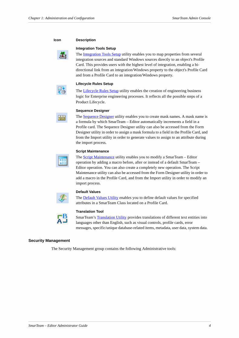
The Application Tools group contains the following Administrative tools:
SmarTeam – Editor Administrator Guide 3
Chapter 1: Administration and Configuration SmarTeam Admin Console
Security Management
The Security Management group contains the following Administrative tools:
Icon Description
Integration Tools SetupThe Integration Tools Setup utility enables you to map properties from several integration sources and standard Windows sources directly to an object's Profile Card. This provides users with the highest level of integration, enabling a bi-directional link from an integration/Windows property to the object's Profile Card and from a Profile Card to an integration/Windows property.
Lifecycle Rules Setup
The Lifecycle Rules Setup utility enables the creation of engineering business logic for Enterprise engineering processes. It reflects all the possible steps of a Product Lifecycle.
Sequence DesignerThe Sequence Designer utility enables you to create mask names. A mask name is a formula by which SmarTeam – Editor automatically increments a field in a Profile card. The Sequence Designer utility can also be accessed from the Form Designer utility in order to assign a mask formula to a field in the Profile Card, and from the Import utility in order to generate values to assign to an attribute during the import process.
Script MaintenanceThe Script Maintenance utility enables you to modify a SmarTeam – Editor operation by adding a macro before, after or instead of a default SmarTeam – Editor operation. You can also create a completely new operation. The Script Maintenance utility can also be accessed from the Form Designer utility in order to add a macro in the Profile Card, and from the Import utility in order to modify an import process.
Default ValuesThe Default Values Utility enables you to define default values for specified attributes in a SmarTeam Class located on a Profile Card.
Translation Tool SmarTeam’s Translation Utility provides translations of different text entities into languages other than English, such as visual controls, profile cards, error messages, specific/unique database-related items, metadata, user data, system data.
SmarTeam – Editor Administrator Guide 4

Chapter 1: Administration and Configuration SmarTeam Admin Console
Workflow Management
The Workflow Management group contains the following Administrative tools:
Vault Management
The Vault Management group contains the following Administrative tools:
Icon Description
User MaintenanceThe User Maintenance tool provides for user security measures by setting up passwords and restrictions on various options in SmarTeam – Editor.
Import LDAP UsersThe LDAP/Active Directory Import Wizard enables you to import users of LDAP /Active Directory protocols and to authenticate them against the LDAP/Active Directory server. See Importing LDAP/Active Directory Users for details.
Icon Description
Flowchart DesignerThe Flowchart Designer is an intuitive interface for designing flowcharts. Using the Flowchart Designer, you can create a detailed flowchart, save it and assign it to a Process in a step-by-step manner. See SmarTeam – Workflow Online Help for details.
Workflow ManagerThe WorkFlow Manager provides online viewing and monitoring capabilities for Processes that have already been initiated. Using the WorkFlow Manager search tools, you can locate problematic Processes or those that are causing delays and adjust them on-the-fly. See the SmarTeam – Workflow Online Help for details.
Icon Description
Vault TesterThe Vault Tester utility allows you to check that the Vault Server is working properly by requesting several operations from the vault server.See SmarTeam – Foundation Administration Guide for details.
Vault SetupThe Vault Setup utility allows you to set up SmarTeam vaults and define their location on the network for each SmarTeam database. See SmarTeam – Foundation Administration Guide for details.
SmarTeam – Editor Administrator Guide 5

Chapter 1: Administration and Configuration SmarTeam Admin Console
User Interface Management
The User Interface Management group contains the following Administrative tools:
Additional SmarTeam Administrative ToolsIn addtion to the Admin Tools that can be found in the Admin Console, there are several more admin tools that can be run directly from the Start Menu, Programs, SmarTeam, Admininstrative Tools menu. These tools are listed below.
Authentication Manager: The Authentication Manager is an administrative tool that enables administrators to configure the behavior of the Session Management Service.
Copy Tool Mapping Utility: The Copy Tool Mapping Utility is an administrative tool used to create predefined rules according to which a copy structure or synchronization process is done.
Database Connection Manager: The Database Connection Manager allows you to connect SmarTeam to supported databases. It manages your list of SmarTeam databases. You use it to create and modify connections to SmarTeam databases.
Export: SmarTeam – Editor enables you to export values from a SmarTeam database in order to transfer them to another database.
Full Text Search SQL Script Generator: The Full Text Search SQL Script Generator is an administrative tool that is accessible to administrators only. This tool is used when configuring the FTS functionality after installation in the foundation installation. See SmarTeam-Foundation_Administration_Guide.pdf for more details.
Import: The Import utility enables you to import values for specified attributes in order to create new objects in SmarTeam's database. SmarTeam – Editor enables you to prepare various tasks for Import processes using the Import utility, save them in the database and execute them when needed.
SmarTeam Data Model Designer: The Data Model Designer enables you to build a SmarTeam database structure precisely suited to your needs, and provides numerous templates for your selection.
SmarTeam Data Model Documentation Wizard: Create documentation from a selected data-base on the database schema.
SmarTeam System Configuration Editor: The System Configuration Editor is an administra-tive tool that is accessible to administrators only. To access the System Configuration Editor, the user needs to provide authentication by supplying the user name and password. See SmarTeam System Configuration Services.pdf for details on the System Configuration Editor.
Icon Description
Menu Editor
Web Form Designer
Form Designer
SmarTeam – Editor Administrator Guide 6
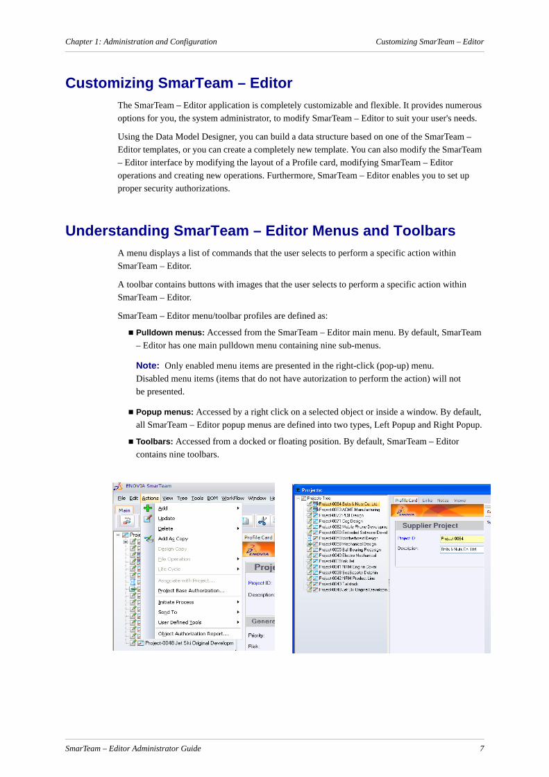
Chapter 1: Administration and Configuration Customizing SmarTeam – Editor
Customizing SmarTeam – Editor The SmarTeam – Editor application is completely customizable and flexible. It provides numerous options for you, the system administrator, to modify SmarTeam – Editor to suit your user's needs.
Using the Data Model Designer, you can build a data structure based on one of the SmarTeam – Editor templates, or you can create a completely new template. You can also modify the SmarTeam – Editor interface by modifying the layout of a Profile card, modifying SmarTeam – Editor operations and creating new operations. Furthermore, SmarTeam – Editor enables you to set up proper security authorizations.
Understanding SmarTeam – Editor Menus and ToolbarsA menu displays a list of commands that the user selects to perform a specific action within SmarTeam – Editor.
A toolbar contains buttons with images that the user selects to perform a specific action within SmarTeam – Editor.
SmarTeam – Editor menu/toolbar profiles are defined as:
Pulldown menus: Accessed from the SmarTeam – Editor main menu. By default, SmarTeam – Editor has one main pulldown menu containing nine sub-menus.
Note: Only enabled menu items are presented in the right-click (pop-up) menu. Disabled menu items (items that do not have autorization to perform the action) will not be presented.
Popup menus: Accessed by a right click on a selected object or inside a window. By default, all SmarTeam – Editor popup menus are defined into two types, Left Popup and Right Popup.
Toolbars: Accessed from a docked or floating position. By default, SmarTeam – Editor contains nine toolbars.
SmarTeam – Editor Administrator Guide 7
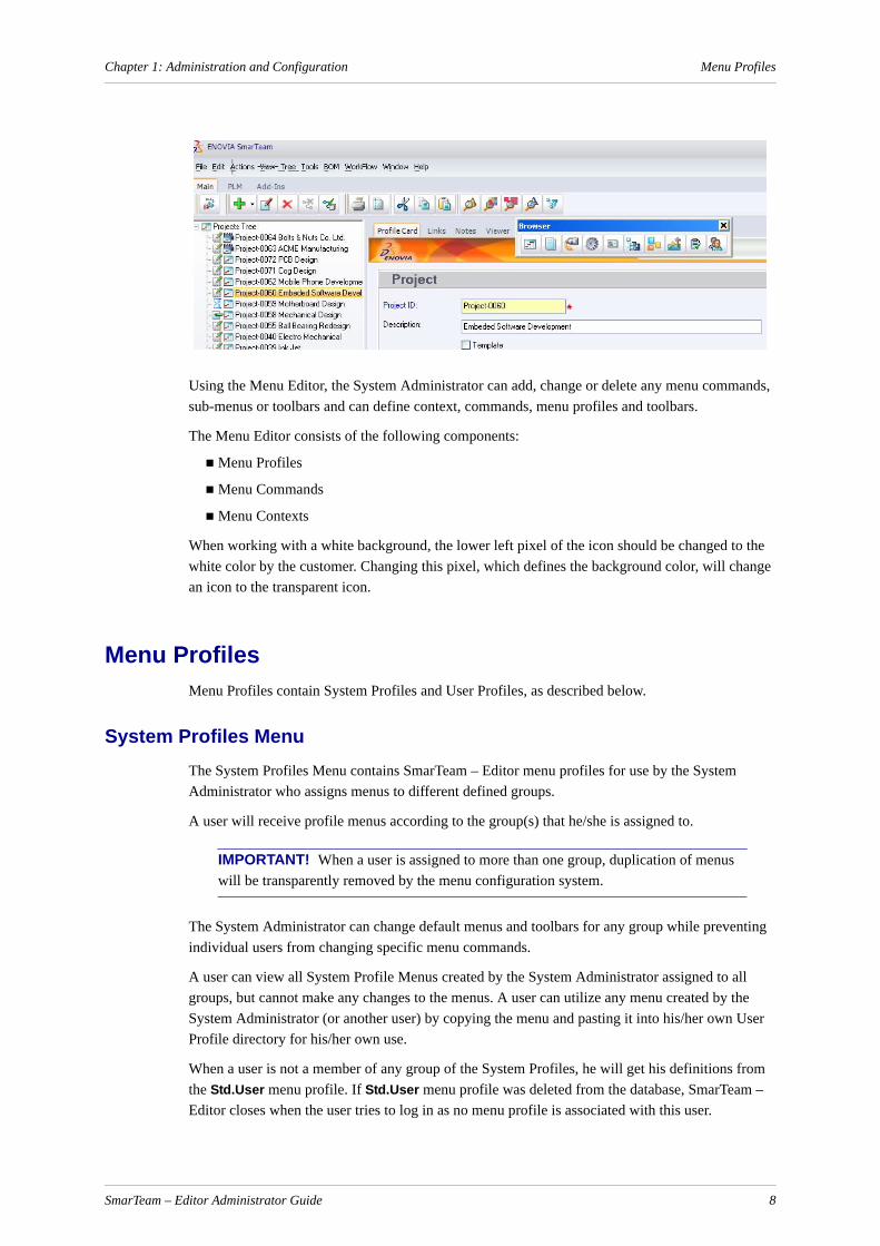
Chapter 1: Administration and Configuration Menu Profiles
Using the Menu Editor, the System Administrator can add, change or delete any menu commands, sub-menus or toolbars and can define context, commands, menu profiles and toolbars.
The Menu Editor consists of the following components:
Menu Profiles
Menu Commands
Menu Contexts
When working with a white background, the lower left pixel of the icon should be changed to the white color by the customer. Changing this pixel, which defines the background color, will change an icon to the transparent icon.
Menu ProfilesMenu Profiles contain System Profiles and User Profiles, as described below.
System Profiles MenuThe System Profiles Menu contains SmarTeam – Editor menu profiles for use by the System Administrator who assigns menus to different defined groups.
A user will receive profile menus according to the group(s) that he/she is assigned to.
IMPORTANT! When a user is assigned to more than one group, duplication of menus will be transparently removed by the menu configuration system.
The System Administrator can change default menus and toolbars for any group while preventing individual users from changing specific menu commands.
A user can view all System Profile Menus created by the System Administrator assigned to all groups, but cannot make any changes to the menus. A user can utilize any menu created by the System Administrator (or another user) by copying the menu and pasting it into his/her own User Profile directory for his/her own use.
When a user is not a member of any group of the System Profiles, he will get his definitions from the Std.User menu profile. If Std.User menu profile was deleted from the database, SmarTeam – Editor closes when the user tries to log in as no menu profile is associated with this user.
SmarTeam – Editor Administrator Guide 8
Chapter 1: Administration and Configuration Menu Commands
User Profiles MenuThe User Profiles Menu contains profiles for the logged on user and any other profile of menu command items changed by any other user(s). When a user is assigned to one or more groups, the logged on user profile is a blueprint of the merged group profiles. Command items are displayed grayed out until a user makes any changes. After changes have been made, the Command Item is displayed in normal, black text.
A user can make changes to his/her assigned User Profiles Menu to further customize his/her SmarTeam – Editor interface via the Menu Editor utility. Once customized, the user can log in to SmarTeam – Editor on any computer and access his/her customized menu profiles.
If a user profile for a logged-on user is deleted, another user profile (blueprint) will be created when he/she next logs on to the Menu Editor utility.
Menu CommandsMenus contain commands that the user selects to perform the selected action.
There are three different types of commands, as follows:
Standard Commands
User-defined Commands (scripts)
Custom commands (currently not available in this version)
Standard CommandsStandard Commands are defined SmarTeam internal commands attached to menus to perform a defined action. Standard commands cannot be changed.
User-defined Commands (scripts)User-defined Commands are scripts that can be defined by the Administrator or user and attached to a menu to perform a defined action. A User-defined Command can be created using the SmarTeam utility, User-defined Tools, accessed from the Tools pulldown menu in the SmarTeam – Editor main menu. Refer to User-Defined Operations for further details.
Custom commands (currently not available in this version)Custom Commands are API commands.
Menu ContextsContext settings define user positioning, such as which SmarTeam – Editor window is active, which entries are selected (if any). Context settings enable commands to be performed on an available selected object.
Context settings have two states: Positive and Negative.
When a context setting is defined as Positive, the command will run on the selected context setting.
SmarTeam – Editor Administrator Guide 9

Chapter 1: Administration and Configuration Effects of Changes in the Administrative Tools
When a context setting is defined as Negative, the command will not run on the selected context setting. (A command will not even appear in a menu when a negative context setting is defined.)
There are two types of context settings:
Internal
Custom
Internal contexts are defined SmarTeam context settings attached to menus to define a specific user position. Internal contexts cannot be changed.
Custom contexts are created using an API and attached to a menu to define a specific user position. Each view defined by the API contains a context that can be added to the SmarTeam – Editor interface using this function.
Effects of Changes in the Administrative ToolsWhen changes are made in the Administrative Tools, either via the Admin Console or via the Admin Tools list, it is highly recommended that all users are logged out from SmarTeam. This is due to the fact that these changes may affect the system behavior in different ways. For some tools changes only take affect when the user has logged out and relogged into SmarTeam, while for some tools changes take affect immediately.
The tools listed here are divided into the following categories:
Changes to be Made Only when Setting Up the Environment
Changes That Require User Relogin
Changes That Do Not Require User Relogin
Changes to be Made Only when Setting Up the EnvironmentFor the following Admin Tools, it is recommended to only make changes when setting up the environment. Changes should not be made to a working/production environment.
Authentication Manager
Data Model Designer
System Configuration Editor
Database Connection Manager
Changes That Require User ReloginWhen a user is connected to SmarTeam and working, the SmarTeam system collects metadata of different objects. Therefore, for the following Admin tools, changes made by the administrator will only take affect after the user has logged out and relogged into SmarTeam.
Integration Tool Setup
Lifecycle Rule Setup
Sequence Designer
Script Maintenance
Default Values
SmarTeam – Editor Administrator Guide 10
Chapter 1: Administration and Configuration Effects of Changes in the Administrative Tools
Translation Tool
User Maintenance
Vault Setup
Menu Editor
Form Designer
Database Connection Manager
System Configuration Editor
Authentication Manager
Note: For Database Connection Manager, System Configuration Editor and Authentica-tion Manager, it is highly recommended that changes be made only at environment setup. In any event, any additional changes require logging in again.
Changes That Do Not Require User ReloginFor the following Admin tools, changes can be made when users are logged and will take affect immediately:
Import LDAP Users
Flowchart Designer
Workflow Manager
Vault Monitor
Vault Tester
Export
Import
SmarTeam – Editor Administrator Guide 11
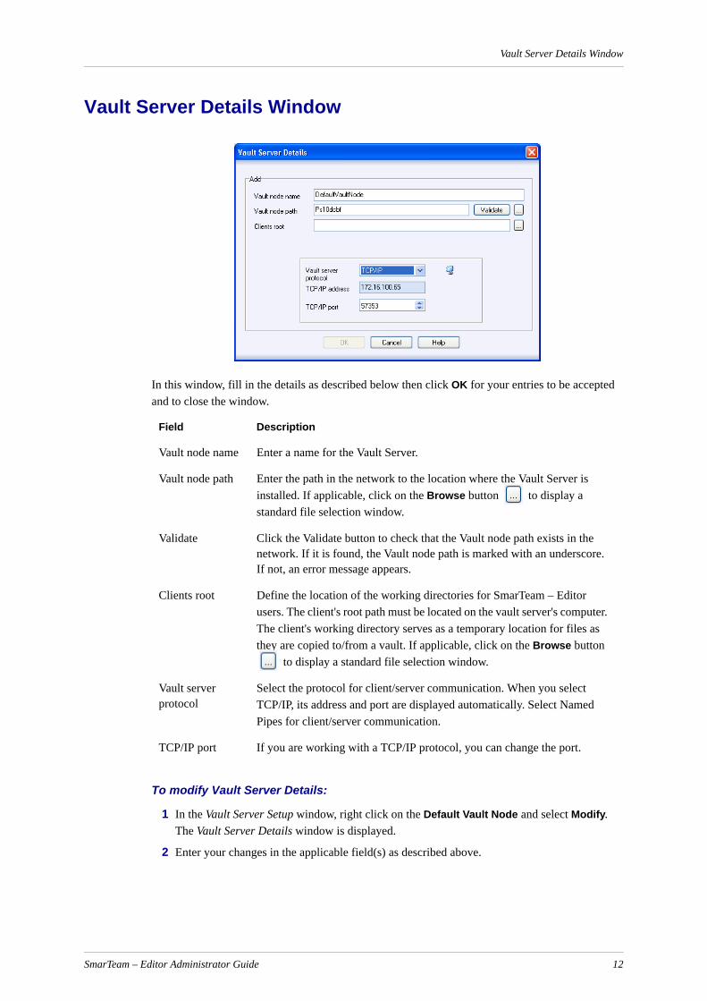
Vault Server Details Window
Vault Server Details Window
In this window, fill in the details as described below then click OK for your entries to be accepted and to close the window.
To modify Vault Server Details:
1 In the Vault Server Setup window, right click on the Default Vault Node and select Modify. The Vault Server Details window is displayed.
2 Enter your changes in the applicable field(s) as described above.
Field Description
Vault node name Enter a name for the Vault Server.
Vault node path Enter the path in the network to the location where the Vault Server is installed. If applicable, click on the Browse button to display a standard file selection window.
Validate Click the Validate button to check that the Vault node path exists in the network. If it is found, the Vault node path is marked with an underscore. If not, an error message appears.
Clients root Define the location of the working directories for SmarTeam – Editor users. The client's root path must be located on the vault server's computer. The client's working directory serves as a temporary location for files as they are copied to/from a vault. If applicable, click on the Browse button
to display a standard file selection window.
Vault server protocol
Select the protocol for client/server communication. When you select TCP/IP, its address and port are displayed automatically. Select Named Pipes for client/server communication.
TCP/IP port If you are working with a TCP/IP protocol, you can change the port.
SmarTeam – Editor Administrator Guide 12
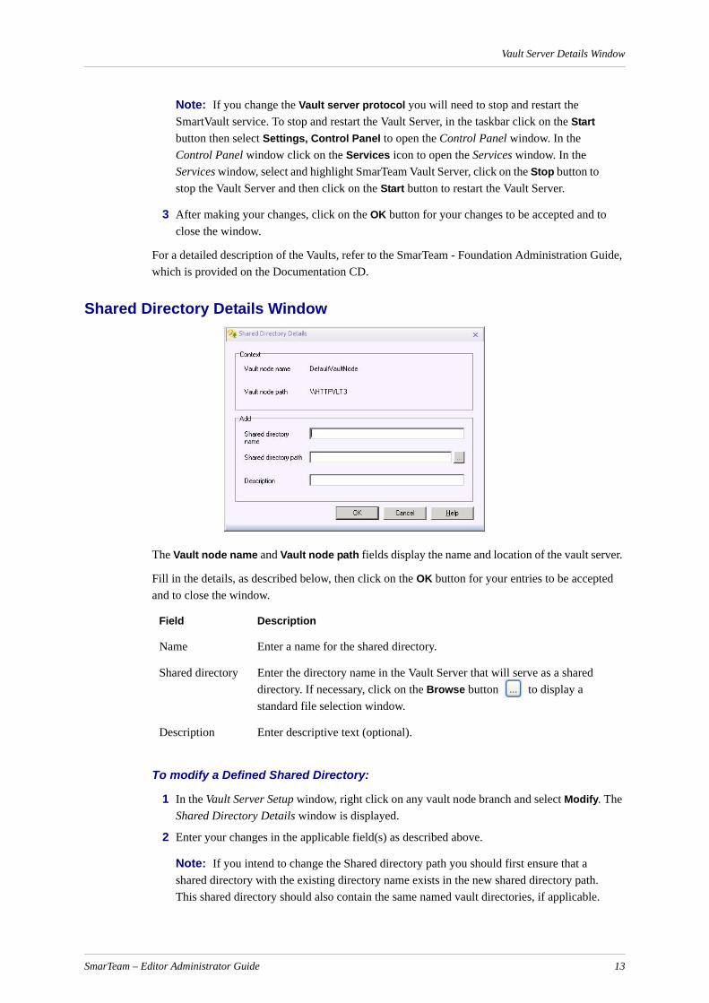
Vault Server Details Window
Note: If you change the Vault server protocol you will need to stop and restart the SmartVault service. To stop and restart the Vault Server, in the taskbar click on the Start button then select Settings, Control Panel to open the Control Panel window. In the Control Panel window click on the Services icon to open the Services window. In the Services window, select and highlight SmarTeam Vault Server, click on the Stop button to stop the Vault Server and then click on the Start button to restart the Vault Server.
3 After making your changes, click on the OK button for your changes to be accepted and to close the window.
For a detailed description of the Vaults, refer to the SmarTeam - Foundation Administration Guide, which is provided on the Documentation CD.
Shared Directory Details Window
The Vault node name and Vault node path fields display the name and location of the vault server.
Fill in the details, as described below, then click on the OK button for your entries to be accepted and to close the window.
To modify a Defined Shared Directory:
1 In the Vault Server Setup window, right click on any vault node branch and select Modify. The Shared Directory Details window is displayed.
2 Enter your changes in the applicable field(s) as described above.
Note: If you intend to change the Shared directory path you should first ensure that a shared directory with the existing directory name exists in the new shared directory path. This shared directory should also contain the same named vault directories, if applicable.
Field Description
Name Enter a name for the shared directory.
Shared directory Enter the directory name in the Vault Server that will serve as a shared directory. If necessary, click on the Browse button to display a standard file selection window.
Description Enter descriptive text (optional).
SmarTeam – Editor Administrator Guide 13
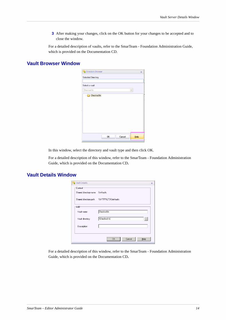
Vault Server Details Window
3 After making your changes, click on the OK button for your changes to be accepted and to close the window.
For a detailed description of vaults, refer to the SmarTeam - Foundation Administration Guide, which is provided on the Documentation CD.
Vault Browser Window
In this window, select the directory and vault type and then click OK.
For a detailed description of this window, refer to the SmarTeam - Foundation Administration Guide, which is provided on the Documentation CD.
Vault Details Window
For a detailed description of this window, refer to the SmarTeam - Foundation Administration Guide, which is provided on the Documentation CD.
SmarTeam – Editor Administrator Guide 14

Vault Server Details Window
Vault Data Window
For a detailed description of this window, refer to the SmarTeam - Foundation Administration Guide, which is provided on the Documentation CD.
Vault Maintenance
For a detailed description of this window, refer to the SmarTeam - Foundation Administration Guide, which is provided on the Documentation CD.
Running the Vault Default Utility The Vault Default utility is installed in the SmarTeam\bin directory during installation of the Vault Server utilities. The Vault Default utility runs automatically and installs vault default directories on the server during installation.
If you want to define vault default directories for a new database or if the installation failed to install vault default directories, you can run the Vault Default utility.
To run the Vault Default Utility:
1 Locate the SmarTeam\BIN directory and double-click on the file named vaultdefault.exe.
2 The SmarTeam – Editor User Login window now appears. Enter your User name and Password, if necessary then click on the OK button for your entries to be accepted and to close the window.
SmarTeam – Editor Administrator Guide 15

Vault Server Details Window
After successful login The Vault Default window is displayed.
3 Click the Browse button and select a database from the displayed list or from the File menu select Switch to Database and select a SmarTeam database.
4 In the Vault Default window click Start. The displayed window lists the default directories that will be created.
5 Select the appropriate protocol and click OK. The vaults default directories are created.
When you open the Vault Setup utility in order to define your vault structure, these default locations are displayed.
Note: You can also display the above window by selecting the Create Default Environment option from the Vault Server Setup window.
Changing Vault Service ParametersThe Set Service Dependency utility is installed in the SmarTeam/Bin directory during installation of the Vault Server utilities. It enables you to change the default installation parameters for the Vault Service. In addition, the Set Service Dependency utility enables you to install/uninstall or start/stop the Vault Service.
To change the Vault Service Parameters:
1 Locate the SmarTeam\bin directory and double-click on the file named SetServiceDependency.exe
OR
From the Run window, enter the following: SetServiceDependency.exe -Manual
2 Click OK to run the Set Service Dependency utility. The Service Setup window is displayed.
The Available list box lists the services that are currently installed on your server.
The Selected list box lists the services that must be invoked before the Vault Service.
The User Name and Password refer to the Vault Service user.
SmarTeam – Editor Administrator Guide 16
Vault Server Details Window
3 If the Vault Server runs on the same computer as the database server, check that the following services are displayed in the Selected list box:
ORACLE Service (Oracle database server)
Interbase Server
Connect SQL Net (SQL service)
If these services are not displayed in the Selected list box, move them to the Selected list box (using the arrow buttons).
Note: These services must run in conjunction with the Vault Service, so that the Vault Service will have access to the database.
4 If you want to define additional services that must be invoked before the Vault Service, move these services into the Selected list box.
5 In the Account Name field, enter the user account for the Vault Service. Be sure to include the domain name when necessary. In the Password field, enter the password of the user.
Note: Keep in mind that the assigned user must be a member of the Vault Administrators group. You can view a list of users and the groups in the User Manager window.
6 Click Install to install the Vault Service.
SmarTeam – Editor Administrator Guide 17

Lookup Tables
SmarTeam – Editor Administrator Guide 18
Lookup Tables
Creating a Lookup FieldA lookup field is created in the Data Model Designer. A lookup field appears in the Profile Card as a dropdown list, enabling the you to select a defined option.
To create a lookup field:
1 Define the values of a Lookup Table.
The Lookup Tables option is accessed from the SmarTeam – Editor menu bar (not the Form Designer menu bar). See Defining the Values of a Lookup Table for details of how to defining values for a Lookup Table.
2 Add a lookup field in the Working Form.
3 Select a name for this field from the list of previously-defined Lookup Tables.
For example: You can create a Lookup Table (using the Data Model Designer) named Phase and assign values for it such as Design, Development and Testing. In the Working Form, you can then create a lookup field and select File Type in the Lookup field of the Properties window. When a user clicks the arrow to the right of the File Type field in the Profile Card, a dropdown list is displayed with three options, Design, Development and Testing.
Adding a Lookup Field in the Working FormYou can add or modify a Lookup field using the Working Form. When the Properties window is displayed, you can select the name of the Lookup Table that will be displayed in the Profile Card for this field.
To add a Lookup field:
1 Click on the Lookup tool from the Form Designer toolbar. Click and drag the mouse in the Working Form to define the location and size of the Lookup field. The Properties window is displayed.
2 In the Column field of the Properties window, select the database field to be linked to this field. The value selected by you for this field is stored in the appropriate Column of the database.
3 The selected database name appears in the Lookup Name field of the Properties window.
In the Profile Card, this field will display a dropdown list of options when the user clicks the arrow to the right of the field. You can then select one option from the list.

User Maintenance
User MaintenanceThis chapter provides operating instructions for setting up access permissions in SmarTeam – Editor.
SmarTeam includes three kinds of administrative objects that represent individual users and sets of users: Users, Groups and Roles.
The primary function of these objects is to allow you to control the information users can see and the tasks they can perform. This chapter explains the conditions in which you should define these administrative objects and describes how to define each object.
The User Maintenance tool provides for user security measures by setting up passwords and restrictions on various options in SmarTeam – Editor.
For example: The system administrator might define that only supervisors can use the New Release options while all users can use the View option. The system administrator might also define that the group named Clerical can execute the Edit and View options on objects in New and Checked In state, but it cannot use the Add or Delete options in the Released or Obsolete state.
Global security is the security set in the system per group of people or global role through the User Maintanance tool. See Assigning Authorizations for details. Unless specified otherwise, the term "security" in this section refers to global security.
This tool enables the System Administrator to perform the following tasks:
Define new users
Define groups
Define roles
Assign authorizations or access permissions for user groups or roles.
Define passwords for users.
Note: Users without administrator rights can also modify their own passwords.
To access the User Maintenance Tool:
1 From the Admin Console select Security Management, Users Maintenance.
2 The Login window appears.
3 Login with your user name and password.
4 The User Maintenance Administration window appears:
SmarTeam – Editor Administrator Guide 19
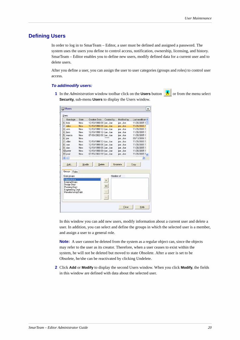
User Maintenance
Defining UsersIn order to log in to SmarTeam – Editor, a user must be defined and assigned a password. The system uses the users you define to control access, notification, ownership, licensing, and history. SmarTeam – Editor enables you to define new users, modify defined data for a current user and to delete users.
After you define a user, you can assign the user to user categories (groups and roles) to control user access.
To add/modify users:
1 In the Administration window toolbar click on the Users button or from the menu select Security, sub-menu Users to display the Users window.
In this window you can add new users, modify information about a current user and delete a user. In addition, you can select and define the groups in which the selected user is a member, and assign a user to a general role.
Note: A user cannot be deleted from the system as a regular object can, since the objects may refer to the user as its creator. Therefore, when a user ceases to exist within the system, he will not be deleted but moved to state Obsolete. After a user is set to be Obsolete, he/she can be reactivated by clicking Undelete.
2 Click Add or Modify to display the second Users window. When you click Modify, the fields in this window are defined with data about the selected user.
SmarTeam – Editor Administrator Guide 20
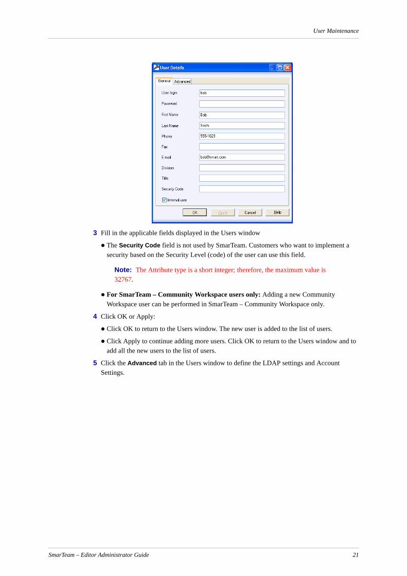
User Maintenance
3 Fill in the applicable fields displayed in the Users window
The Security Code field is not used by SmarTeam. Customers who want to implement a security based on the Security Level (code) of the user can use this field.
Note: The Attribute type is a short integer; therefore, the maximum value is 32767.
For SmarTeam – Community Workspace users only: Adding a new Community Workspace user can be performed in SmarTeam – Community Workspace only.
4 Click OK or Apply:
Click OK to return to the Users window. The new user is added to the list of users.
Click Apply to continue adding more users. Click OK to return to the Users window and to add all the new users to the list of users.
5 Click the Advanced tab in the Users window to define the LDAP settings and Account Settings.
SmarTeam – Editor Administrator Guide 21

User Maintenance
Note: The User Management frame in the Advanced tab is enabled if User Account Management is selected as the Database mechanism.
6 Fill in the applicable fields displayed in the Users window:
7 Click Apply to save your changes and continue working on same window, or OK to save your changes and close the window. Click Cancel to close the window without any changes being accepted.
Copying a User’s Groups and Roles to Another User
In the User Maintenance utility, a user’s groups and roles can be copied to another user, either overwriting the existing groups and roles or being added to them.
To copy a user’s groups and roles to another user:
1 Select a user from the list of users.
Inactive Select this check box to make the user's account is inactive.
User Locked The user can be locked under two scenarios. Either the Administrator has locked the user out of the system, or the user has attempted to login with the wrong password more than the permitted number of times in the account lockout threshold. The Administrator configures this threshold in the SmarTeam preferences. If configured to zero, users are allowed unlimited attempts at logging in.
Password Expiration Date
The date by which the password expires, expressed in days. If it is null, the password never expires.
Password Algorithm
There are two possible modes: plain text and MD5, which is a hash password.
Can use Project Management
Check this box to allow the user to access the SmarTeam – Program Management utility from within SmarTeam – Editor and SmarTeam – Web Editor.
SmarTeam – Editor Administrator Guide 22

User Maintenance
2 Click Copy.
3 The Copy Users Groups window appears:
4 Select the Groups check box to copy groups and/or the Roles check box to copy roles.
5 From the To Users list, select the user to which the groups and roles will be copied.
6 Select Override current groups and roles to overwrite the user’s existing groups and roles or unselect to add the groups and roles to the user’s existing groups and roles.
7 Click OK to perform the copy and return to the User Maintenance window.
Assigning a User to Groups and Roles
Note: If the Workflow mechanism was added in the Data Model Designer, whenever a user is added to a group or updated in a group in the User Maintenance, SmarTeam checks whether a Workflow license exists. If a license is not found, an error message will appear. To avoid this problem, either remove the Workflow mechanism in the Data Model Designer if it is not needed or purchase a Workflow license.
To assign a user to a group/role:
1 In the Users window you can define the group(s) to which the user belongs:
Click the Group tab at the bottom of the screen.
Select a user(s) from the list of users in the upper side of the screen.
Using the Arrow buttons, move the groups for the selected user from the available User Groups into the Member of box of each user.
Note:
a A user can belong to more than one group. For example, a senior engineer can belong to Supervisors and Engineers group.
b When selecting multiple users, you can add these users to a group, but cannot remove them from the group.
SmarTeam – Editor Administrator Guide 23

User Maintenance
2 In the Users window you can define the global roles to be assigned to a user.
Click the Role tab at the bottom of the screen.
Select a user from the list of users in the left side of the screen.
Using the Arrow buttons, assign roles to each user.
When to Create a Group and When a RoleWhen many SmarTeam users need to have similar authorization over SmarTeam objects from different classes, you should consider creating a group or role to represent this set of users.
To decide which kind of user category you should create, consider what the users have in common and why they need some of the same accesses.
A Group is a collection of people who work on a common project, have a common history, or share a common set of functional skills. In a group, users may act in different roles. For example, an engineering group might include managerial and designer users.
A Role is collection of people who have a common job type: QA Tester, Project Manager, Buyer, Designer and so on.
Defining Groups and Roles
Defining Groups
SmarTeam enables you to define groups of users in order to assign different authorizations, or access permissions, thereby assigning these authorizations to many users at one time. When you create a new user, you can choose the groups in which the selected user is a member.
To define a group:
1 In the Administration toolbar click on the Groups button or from the Administration main menu select Security, sub-menu Groups to display the Authorization Groups window.
2 To create a new group, in the Authorization Groups window click Add to display the second Authorization Groups window.
3 In the Authorization Groups window, enter a suitable group name and click OK or Apply:
Click OK for your entry to be accepted and to return to the previous window. The new group name is added to the list of groups.
Click Apply to continue adding more groups. To return to the previous window, click OK. All new group names are now added to the list of groups.
4 To modify an existing group, in the Authorization Groups window, click Modify to display the Authorization Groups window. The selected group name appears in the Group Name field.
Modify the group name as required then click OK to return to the previous window. The modified group name is added to the list of groups.
5 To delete an existing group, in the Authorization Groups window, select and highlight the group name you want to delete then click Delete.
A warning message appears, requesting confirmation to delete the selected group name.
Click OK to continue and delete the selected group, or Cancel to abort the operation and return to the Authorization Groups window.
SmarTeam – Editor Administrator Guide 24
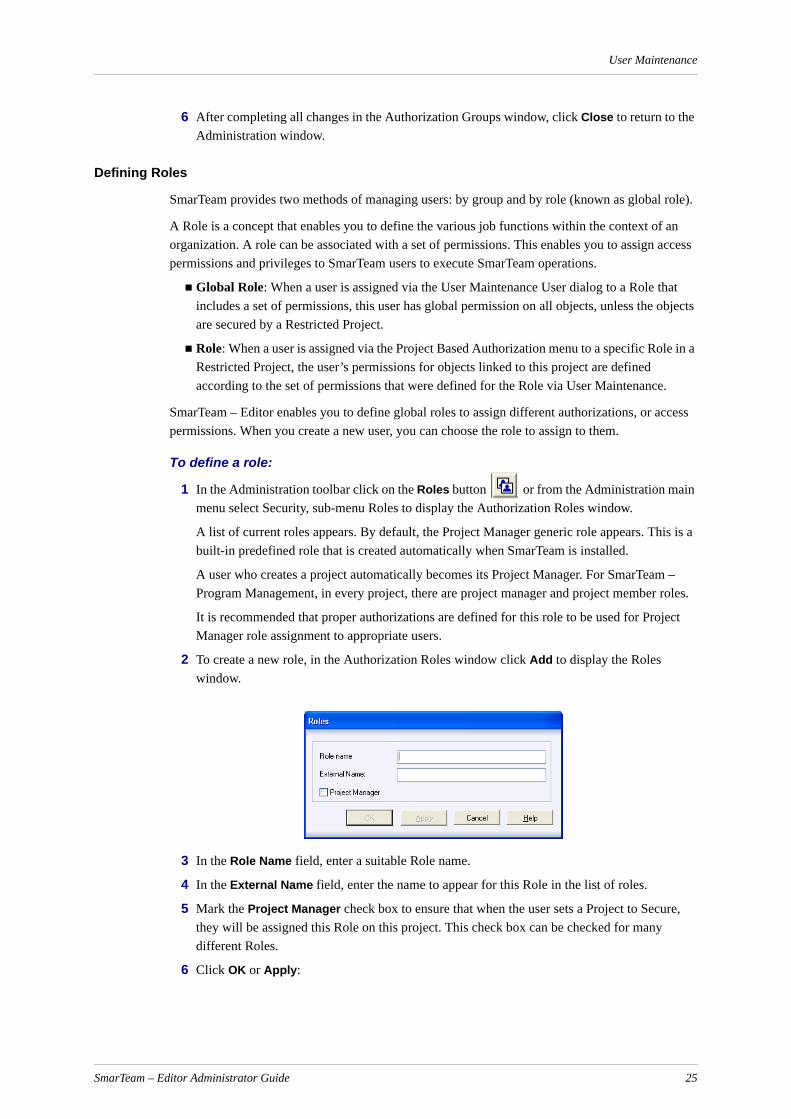
User Maintenance
6 After completing all changes in the Authorization Groups window, click Close to return to the Administration window.
Defining Roles
SmarTeam provides two methods of managing users: by group and by role (known as global role).
A Role is a concept that enables you to define the various job functions within the context of an organization. A role can be associated with a set of permissions. This enables you to assign access permissions and privileges to SmarTeam users to execute SmarTeam operations.
Global Role: When a user is assigned via the User Maintenance User dialog to a Role that includes a set of permissions, this user has global permission on all objects, unless the objects are secured by a Restricted Project.
Role: When a user is assigned via the Project Based Authorization menu to a specific Role in a Restricted Project, the user’s permissions for objects linked to this project are defined according to the set of permissions that were defined for the Role via User Maintenance.
SmarTeam – Editor enables you to define global roles to assign different authorizations, or access permissions. When you create a new user, you can choose the role to assign to them.
To define a role:
1 In the Administration toolbar click on the Roles button or from the Administration main menu select Security, sub-menu Roles to display the Authorization Roles window.
A list of current roles appears. By default, the Project Manager generic role appears. This is a built-in predefined role that is created automatically when SmarTeam is installed.
A user who creates a project automatically becomes its Project Manager. For SmarTeam – Program Management, in every project, there are project manager and project member roles.
It is recommended that proper authorizations are defined for this role to be used for Project Manager role assignment to appropriate users.
2 To create a new role, in the Authorization Roles window click Add to display the Roles window.
3 In the Role Name field, enter a suitable Role name.
4 In the External Name field, enter the name to appear for this Role in the list of roles.
5 Mark the Project Manager check box to ensure that when the user sets a Project to Secure, they will be assigned this Role on this project. This check box can be checked for many different Roles.
6 Click OK or Apply:
SmarTeam – Editor Administrator Guide 25
User Maintenance
Click OK for your entry to be accepted and to return to the previous window. The new role name is added to the list of roles.
Click Apply to continue adding more roles. To return to the previous window, click OK. All new Role names are now added to the list of Roles.
7 To modify an existing Role, in the Authorization Roles window, click Modify to display the Authorization Roles window.
The selected role name appears in the Role Name field.
8 Modify the Role name as required then click OK to return to the previous window. The modified Role name is added to the list of Roles.
9 To delete an existing role, in the Authorization roles window, select and highlight the role name you want to delete then click Delete.
A warning message will appear, requesting confirmation to delete the selected role name.
10 Click OK to continue and delete the selected role or click Cancel to abort the operation and return to the Authorization role window.
11 After completing all changes in the Authorization Roles window click Close to return to the Administration window.
Define User PasswordsThe initial user password is defined when a new user is first created in the Users window. Any administrative or non-administrative user can redefine his/her own password.
To define a user password:
1 In the Administration window toolbar click the Password button or from the menu select Security, Password to display the Users window.
2 Enter a password in the Password field. Confirm your password by entering the same password in the Confirm Password field. (For security purposes, asterisks are displayed in the Confirm Password field when you enter your confirmation.)
3 Click OK for your new password to be accepted – or click Cancel to abort any changes made – and to close the window.
Password Rules
When changing a password, the following rules must be adhered to:
The password must not be identical to the last password used.
The password must not contain the user’s user name or full name.
Note: This rule is only valid only if the system configuration key Preferences.NoUserNameinPassword is set to True. If this key is False, the system does not check for this.
SmarTeam – Editor Administrator Guide 26
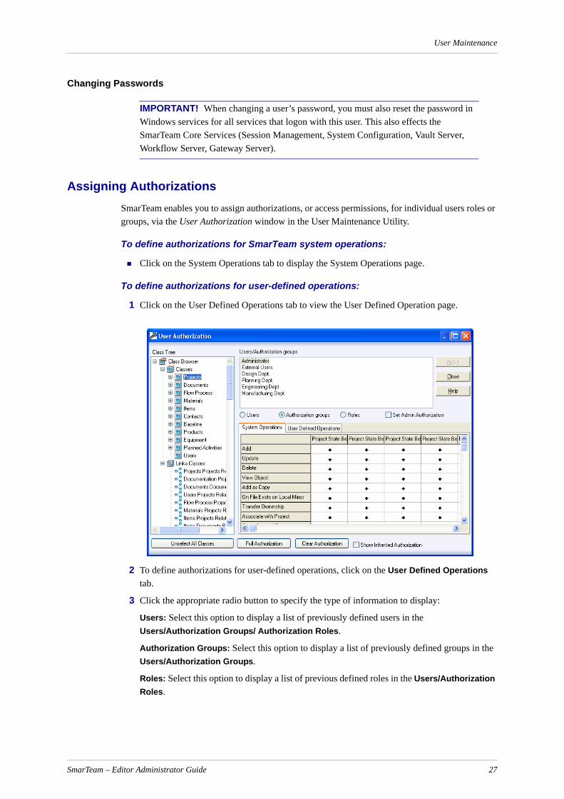
User Maintenance
Changing Passwords
IMPORTANT! When changing a user’s password, you must also reset the password in Windows services for all services that logon with this user. This also effects the SmarTeam Core Services (Session Management, System Configuration, Vault Server, Workflow Server, Gateway Server).
Assigning AuthorizationsSmarTeam enables you to assign authorizations, or access permissions, for individual users roles or groups, via the User Authorization window in the User Maintenance Utility.
To define authorizations for SmarTeam system operations:
Click on the System Operations tab to display the System Operations page.
To define authorizations for user-defined operations:
1 Click on the User Defined Operations tab to view the User Defined Operation page.
2 To define authorizations for user-defined operations, click on the User Defined Operations tab.
3 Click the appropriate radio button to specify the type of information to display:
Users: Select this option to display a list of previously defined users in the Users/Authorization Groups/ Authorization Roles.
Authorization Groups: Select this option to display a list of previously defined groups in the Users/Authorization Groups.
Roles: Select this option to display a list of previous defined roles in the Users/Authorization Roles.
SmarTeam – Editor Administrator Guide 27
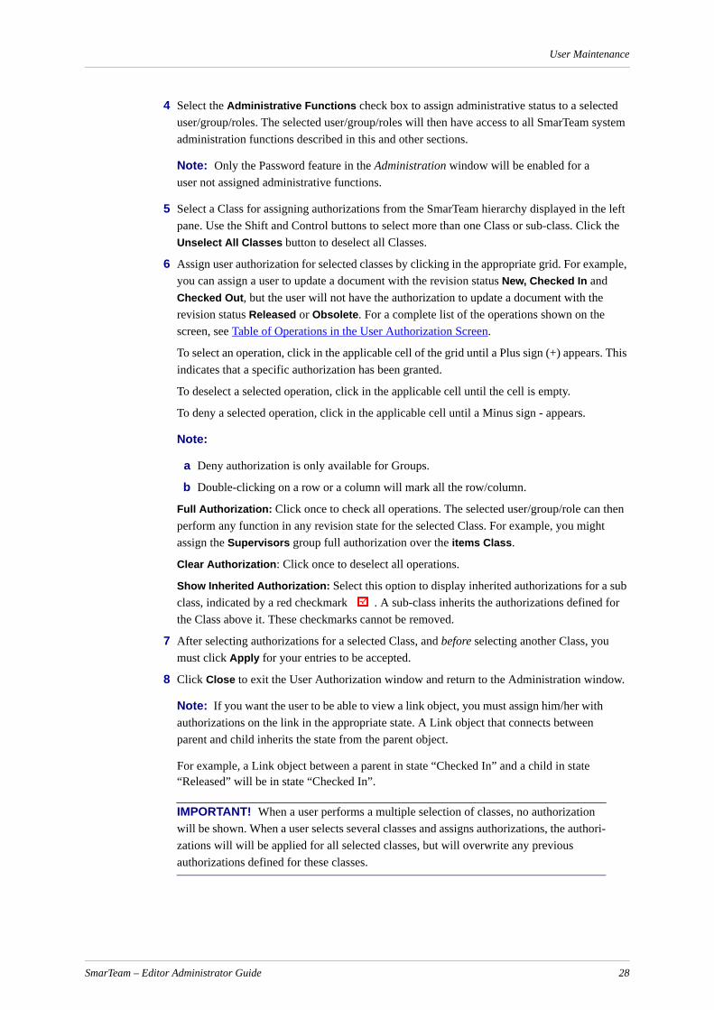
User Maintenance
4 Select the Administrative Functions check box to assign administrative status to a selected user/group/roles. The selected user/group/roles will then have access to all SmarTeam system administration functions described in this and other sections.
Note: Only the Password feature in the Administration window will be enabled for a user not assigned administrative functions.
5 Select a Class for assigning authorizations from the SmarTeam hierarchy displayed in the left pane. Use the Shift and Control buttons to select more than one Class or sub-class. Click the Unselect All Classes button to deselect all Classes.
6 Assign user authorization for selected classes by clicking in the appropriate grid. For example, you can assign a user to update a document with the revision status New, Checked In and Checked Out, but the user will not have the authorization to update a document with the revision status Released or Obsolete. For a complete list of the operations shown on the screen, see Table of Operations in the User Authorization Screen.
To select an operation, click in the applicable cell of the grid until a Plus sign (+) appears. This indicates that a specific authorization has been granted.
To deselect a selected operation, click in the applicable cell until the cell is empty.
To deny a selected operation, click in the applicable cell until a Minus sign - appears.
Note:
a Deny authorization is only available for Groups.
b Double-clicking on a row or a column will mark all the row/column.
Full Authorization: Click once to check all operations. The selected user/group/role can then perform any function in any revision state for the selected Class. For example, you might assign the Supervisors group full authorization over the items Class.
Clear Authorization: Click once to deselect all operations.
Show Inherited Authorization: Select this option to display inherited authorizations for a sub class, indicated by a red checkmark . A sub-class inherits the authorizations defined for the Class above it. These checkmarks cannot be removed.
7 After selecting authorizations for a selected Class, and before selecting another Class, you must click Apply for your entries to be accepted.
8 Click Close to exit the User Authorization window and return to the Administration window.
Note: If you want the user to be able to view a link object, you must assign him/her with authorizations on the link in the appropriate state. A Link object that connects between parent and child inherits the state from the parent object.
For example, a Link object between a parent in state “Checked In” and a child in state “Released” will be in state “Checked In”.
IMPORTANT! When a user performs a multiple selection of classes, no authorization will be shown. When a user selects several classes and assigns authorizations, the authori-zations will will be applied for all selected classes, but will overwrite any previous authorizations defined for these classes.
SmarTeam – Editor Administrator Guide 28
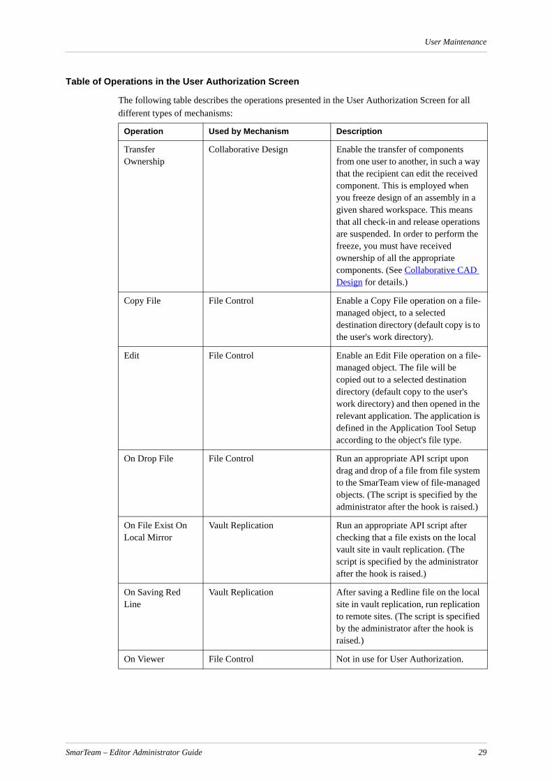
User Maintenance
Table of Operations in the User Authorization Screen
The following table describes the operations presented in the User Authorization Screen for all different types of mechanisms:
Operation Used by Mechanism Description
Transfer Ownership
Collaborative Design Enable the transfer of components from one user to another, in such a way that the recipient can edit the received component. This is employed when you freeze design of an assembly in a given shared workspace. This means that all check-in and release operations are suspended. In order to perform the freeze, you must have received ownership of all the appropriate components. (See Collaborative CAD Design for details.)
Copy File File Control Enable a Copy File operation on a file-managed object, to a selected destination directory (default copy is to the user's work directory).
Edit File Control Enable an Edit File operation on a file-managed object. The file will be copied out to a selected destination directory (default copy to the user's work directory) and then opened in the relevant application. The application is defined in the Application Tool Setup according to the object's file type.
On Drop File File Control Run an appropriate API script upon drag and drop of a file from file system to the SmarTeam view of file-managed objects. (The script is specified by the administrator after the hook is raised.)
On File Exist On Local Mirror
Vault Replication Run an appropriate API script after checking that a file exists on the local vault site in vault replication. (The script is specified by the administrator after the hook is raised.)
On Saving Red Line
Vault Replication After saving a Redline file on the local site in vault replication, run replication to remote sites. (The script is specified by the administrator after the hook is raised.)
On Viewer File Control Not in use for User Authorization.
SmarTeam – Editor Administrator Guide 29

User Maintenance
Print File Control Enable a Print File operation on a file-managed object. The file will be opened in the relevant application. The application is defined in the Application Tool Setup according to the object's file type, and is printed through the application.
Red Line File Control Enable a Red Line operation on a file-managed object. The file will be opened in the relevant application. The application is defined in the Application Tool Setup according to the object's file type, and is red lined through the application.
View File Control Enable a View File operation on a file-managed object. The file will be copied out to a selected destination directory (default copy to the user's work directory) and opened in the relevant application. The application is defined by the Application Tool Setup according to the object's file type. This option can be used to open files through an external viewer.
Add Object Management Enable an Add operation per class object.
Add as Copy Object Management Enable an Add As Copy operation per class object. A new object will be created with the copied attributes from the original object.
Delete Object Management Enable a Delete Object operation per class object. • If the object has links, the user is
asked to approve that he is aware of the links per super class before deletion.
• If the object has a file attached, the user is asked whether or not to delete the attached file.
Send To Email Recipient
Object Management Enable the sending of object metadata through the Email system that resides on the local machine.
Send To SmarTeam Recipient
Object Management Enable the sending of links to object via SmartBox.
Update Object Management Enable an Update operation per class object for profile card attributes.
SmarTeam – Editor Administrator Guide 30
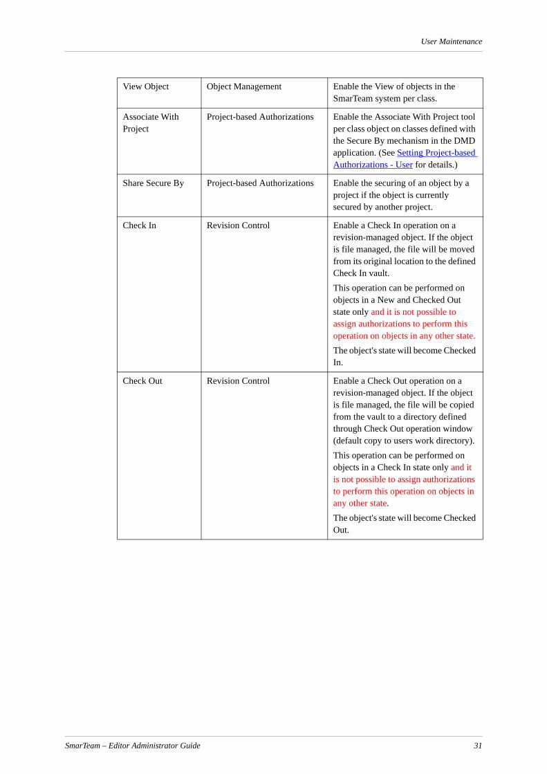
User Maintenance
View Object Object Management Enable the View of objects in the SmarTeam system per class.
Associate With Project
Project-based Authorizations Enable the Associate With Project tool per class object on classes defined with the Secure By mechanism in the DMD application. (See Setting Project-based Authorizations - User for details.)
Share Secure By Project-based Authorizations Enable the securing of an object by a project if the object is currently secured by another project.
Check In Revision Control Enable a Check In operation on a revision-managed object. If the object is file managed, the file will be moved from its original location to the defined Check In vault.This operation can be performed on objects in a New and Checked Out state only and it is not possible to assign authorizations to perform this operation on objects in any other state.The object's state will become Checked In.
Check Out Revision Control Enable a Check Out operation on a revision-managed object. If the object is file managed, the file will be copied from the vault to a directory defined through Check Out operation window (default copy to users work directory).This operation can be performed on objects in a Check In state only and it is not possible to assign authorizations to perform this operation on objects in any other state.The object's state will become Checked Out.
SmarTeam – Editor Administrator Guide 31
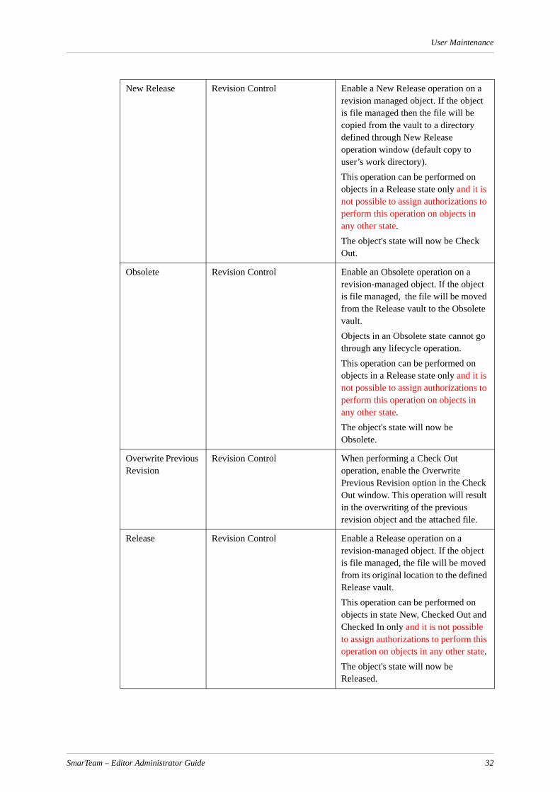
User Maintenance
New Release Revision Control Enable a New Release operation on a revision managed object. If the object is file managed then the file will be copied from the vault to a directory defined through New Release operation window (default copy to user’s work directory).This operation can be performed on objects in a Release state only and it is not possible to assign authorizations to perform this operation on objects in any other state. The object's state will now be Check Out.
Obsolete Revision Control Enable an Obsolete operation on a revision-managed object. If the object is file managed, the file will be moved from the Release vault to the Obsolete vault.Objects in an Obsolete state cannot go through any lifecycle operation.This operation can be performed on objects in a Release state only and it is not possible to assign authorizations to perform this operation on objects in any other state. The object's state will now be Obsolete.
Overwrite Previous Revision
Revision Control When performing a Check Out operation, enable the Overwrite Previous Revision option in the Check Out window. This operation will result in the overwriting of the previous revision object and the attached file.
Release Revision Control Enable a Release operation on a revision-managed object. If the object is file managed, the file will be moved from its original location to the defined Release vault.This operation can be performed on objects in state New, Checked Out and Checked In only and it is not possible to assign authorizations to perform this operation on objects in any other state.The object's state will now be Released.
SmarTeam – Editor Administrator Guide 32

User Maintenance
Undo Check Out Revision Control Enable an Undo Check Out operation on a revision-managed object. The user is prompted to accept the deletion of the object, object's references and attached file.This operation can be performed on objects in a Checked Out state only and it is not possible to assign authorizations to perform this operation on objects in any other state.The object's state will now be Checked In or Released, depending on the object's original state.
User Defined Revision
Revision Control When performing any lifecycle operation, enable the User Defined Revision option in the Lifecycle window. This operation will allow the user to manually set a desired revision for the new object created in the selected Lifecycle mode. Permission for this operation should be assigned to the destination state. For example, if you need to define an Upon Checkin operation, permission should be assigned to the Check In State in User Maintenance.
Initiate Process Work Flow Enable an Initiate Process operation on objects with Workflow mechanism class support.
SmarTeam – Editor Administrator Guide 33

Authorizations
AuthorizationsThere are two types of authorizations in SmarTeam:
Global Authorizations
Project-based Authorizations
Global AuthorizationsSmarTeam – Editor enables you to assign authorizations, or access permissions, for individual users roles or groups, via the User Authorization window in the User Maintenance utility. You can define which SmarTeam operations or user-defined operations an individual user, group or role can perform for each Class in SmarTeam – Editor. Refer to User-Defined Operations for further information.
In addition, for groups, you can specify Deny on an operation. If a group has been marked as Deny (–), any users in that group will not be able to perform that operation regardless of other permission they might have.
You can also define in which revision state an individual user, group or role can work with a file, as shown in the following examples:
In the Items Class (and its sub-classes) you may define that the Supervisors group can perform all operations (Add, Update, Delete, View) on files in any revision state.
The Engineers Role can perform all operations on files that are New, Checked In or Being Modified but they can only view objects that are Released or Obsolete.
The Role Designer can perform all operations on files that are New, Checked In, or Being Modified but can only view objects that are Released or Obsolete.
Note: In order to be able to perform Lifecycle operations such as Check Out and New Release, a user must have “Add” permissions on the relevant link classes (hierarchical links and general links).
For example, if a user performs a Check out operation on an assembly that has a link to project, s/he must have “Add” permissions on the link classes "Documents Tree" and "Documents Project Relations".
Project-based AuthorizationsA project is a class that was assigned with project behavior. There are two types of projects in SmarTeam:
Restricted Projects - Projects in which you can restrict the authorizations for objects that belong to them, compared to the global authorizations. This is implemented using Restricted check box.
Regular projects - Objects belonging to such projects will behave according to the global authorization settings - with the addition of the authorizations given to users who have roles in these projects, determined by their roles.
SmarTeam – Editor Administrator Guide 34

Authorizations
Regular projects will be used in cases where the project and its objects are not confidential.
An object can be related to a project in two ways:
Secured - the authorizations for the object will be determined according to the Project-based authorizations
Unsecured - the authorizations for the object will be determined according to the global SmarTeam authorizations
Note: In project-based authorizations, the "secured by" operation is not set on the association link object directly, but the security on the link object is set according to the object that it associates with the project.
This means that the link object is not handled as a separate object in regard to project-based security, but as a “partner” of the secured object (of type document, item etc.)
This approach supports the concept that an object may be linked to a restricted project but in the same time not take its authorizations (for example, standard items should be accessible to everybody although they may be linked to secured projects too).
The Project Manager defines the users in the project and the roles they receive. When an object is attached to the project for the first time, it can be secured. Once it is secured, it can only be changed by the person who has "Share Secured By" authorization (as set in the User Maintenance option).
When a project is not secured and a project manager is not defined, all users with Delete global permission can delete the project. When a project is not secured and a project manager is defined, only the project manager and administrators can delete the project.
Note: The term "global security" refers to all SmarTeam security that was implemented before project-based authorizations were added.
Users, Objects and Projects Relationship
Within SmarTeam, there are different ways in which user, objects and projects relate to each other. The authorizations on an object depending on the type of relationship it has with its associated project(s) and user(s). These relationships are described below.
Note: The "sum" of authorizations is determined according to the following rules:
Allow + Allow = Allow ("+" and "+" = "+")
Deny + Deny = Deny ("-" and "-" = "-")
Deny + Allow = Deny (""- and "+" = "-")
Allow + Don’t Care = Allow ("+" and " " = "+")
Deny + Don’t Care = Deny ("-" and " " = "-")
Don’t Care + Don’t Care = Don’t Care (" " and " " = " ")
If the result of the sum is Don’t Care, the operation is defined as Deny.
The object is not related to any project or related to an unrestricted (regular) project
The authorizations on such objects are determined according to the sum of all the global authorizations the user has in SmarTeam (User+Groups+Global Roles)
SmarTeam – Editor Administrator Guide 35

Authorizations
The object is related to an unrestricted (regular) project in unsecured relationships
The authorizations on objects that belong to the project are determined according to:
the sum of all the global authorizations the user has in SmarTeam (User+Groups+Global Roles)
The object is related to one restricted project not in a secured relationship
The authorizations on objects that belong to the project are determined according to:
the sum of all the global authorizations the user has in SmarTeam (User+Groups+Global Roles)
The object is related to one restricted project (in a secured relationship)
The authorizations on objects that belong to the project are determined according to:
the sum of all the authorizations he has due to all of his roles in context of this project
The only global settings that are also added are the "deny" operations from the groups to which the user belongs
The object is related to multiple restricted projects (in secured relationships)
If the user has different roles in the different projects to which the object is related, the user will get the sum of all the authorizations from all projects.
The object is related to a mix of restricted and regular projects
Even though the object is related to regular projects, authorizations will be taken as the sum only from all restricted projects to which the object is related in secured relations.
Note: When an object is linked to a secured Folder or Restricted Project, its security context is updated and the Modified By and Modification Date fields are updated as well.
Examples
Example 1Document A is related to project 1 but it is not secured by this project. In this case, the authorization on document A will be determined according to the sum of the global authorizations settings.
Document B is related to project 2 and is secured by this project. In this case, the authorization on document B will be determined according to the roles the user has in project B and the "minuses" he has from global authorizations
Document C is related to project 3 but the project 3 is a regular project. In this case, the authorization on document C will be determined according to the sum of all global authorizations.
Document D is related to project 4 and is secured by this project, but the project is a regular project. In this case, the authorization on document D will be determined according to the roles the user has in project 4, and all his/her global authorizations.
SmarTeam – Editor Administrator Guide 36

Authorizations
Example 2Using the User Maintenance utility, the system administrator defines the following rules:
Joe has a global role of Designer and belongs to the External Users group.
A user with a role Tester is allowed to add and delete documents.
A user with a role Designer is allowed to check in and check out documents.
A user with a role Engineer is allowed to check out and delete a document.
External users are denied from deleting documents.
The manager of project 1 assigned Joe the role of engineer
The manager of project 2 and the manager of project 3 assigned Joe the role of tester
Projects 1 and 2 are regular projects, and project 3 is a restricted project.
This setup is depicted by the following scenario:
The result of these rules is as follows:
Document A: Joe is allowed to check in and check out (from global role designer)
Document B: Joe is allowed to check in and check out (from global role designer and role engineer in project 1) but is denied from deleting as he belongs to the group external users.
Document C: Joe is allowed to check in, check out and add (from global role designer and role engineer in project 1 and role tester in project 2) but is denied from deleting as he belongs to the group external users.
Document D: Joe is allowed to check in and check out (from global role designer)
SmarTeam – Editor Administrator Guide 37

Authorizations
Document E: Joe is allowed to add (from role tester in project 3) but is denied from deleting as he belongs to the group external users.
See Assigning Authorizations for details on how to define the project authorizations for each project.
Users Object Authorizations Flowchart
Setting Up and Enabling Project-Based AuthorizationsThe system administrator sets up project-based authorizations in the SmarTeam Data Model Designer. To do this, s/he must first perform the following tasks:
Add the "Project Security" Database-level Behavior (DLB) to the database. Note that this DLB cannot be removed.
The Class-level behavior (CLB) is automatically assigned to the leading class. Note that this CLB cannot be removed.
To set up project-based authorizations:
1 Enter the Data Model Designer.
2 From the menu, select Database and then select the name of the database that you want to use.
3 Click Modify.
The Available Mechanisms window appears.
SmarTeam – Editor Administrator Guide 38

Authorizations
4 Make sure that the Project Based Authorization check box is checked. If it is not, click to check it.
5 Click Next.
The Classes window appears.
6 For each class that you want to be secured by a project, select the class from the Class Browser and then from the Class Mechanisms, check the Secured by check box.
For example, if you want SolidWorks files to be secured by a project, select SolidWorks from the Class Browser and then check the Secured by check box.
SmarTeam – Editor Administrator Guide 39

Authorizations
7 Click Create to implement the changes into the database.
Note: You can only use project-based authorization on an object if the class to which the object belongs has a project-based authorization behavior mechanism defined.
Setting Project-based Authorizations - User
Associating Objects to a Project
A general user can associate objects with a specific project(s).
After selecting an object, you can associate it to a specific project(s).
If the project is restricted, and you also select to secure the object by the project, the authorizations to access this object and to perform operations on it will be determined by the role of the user in the project and all other restricted projects by which this object is secured.
If the project is not restricted, the authorization is a combination of the project security and class security.
To associate an object to a project(s):
1 Select an object and press the right mouse button.
2 From the menu, select Associate with Project.
The Project Associations window appears.
Note: Each user who has the Associate with Project menu option can open the Project Authorizations Properties window, but only a project manager can set the Project Authorizations
3 Select the check box next to the desired project(s).
Note: By clicking on the check box, you can switch between the options: Only Associate ( ), Associate and secure by ( )
SmarTeam – Editor Administrator Guide 40
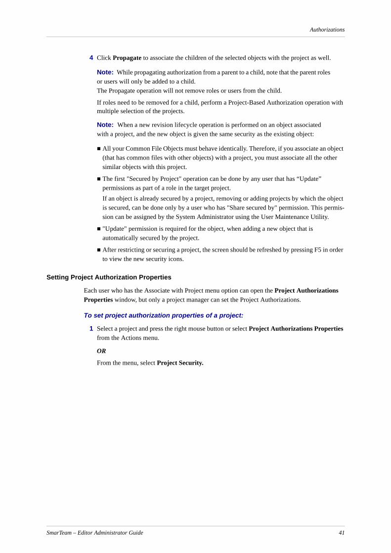
Authorizations
4 Click Propagate to associate the children of the selected objects with the project as well.
Note: While propagating authorization from a parent to a child, note that the parent roles or users will only be added to a child. The Propagate operation will not remove roles or users from the child.
If roles need to be removed for a child, perform a Project-Based Authorization operation with multiple selection of the projects.
Note: When a new revision lifecycle operation is performed on an object associated with a project, and the new object is given the same security as the existing object:
All your Common File Objects must behave identically. Therefore, if you associate an object (that has common files with other objects) with a project, you must associate all the other similar objects with this project.
The first "Secured by Project" operation can be done by any user that has “Update” permissions as part of a role in the target project. If an object is already secured by a project, removing or adding projects by which the object is secured, can be done only by a user who has "Share secured by" permission. This permis-sion can be assigned by the System Administrator using the User Maintenance Utility.
"Update" permission is required for the object, when adding a new object that is automatically secured by the project.
After restricting or securing a project, the screen should be refreshed by pressing F5 in order to view the new security icons.
Setting Project Authorization Properties
Each user who has the Associate with Project menu option can open the Project Authorizations Properties window, but only a project manager can set the Project Authorizations.
To set project authorization properties of a project:
1 Select a project and press the right mouse button or select Project Authorizations Properties from the Actions menu.
OR
From the menu, select Project Security.
SmarTeam – Editor Administrator Guide 41
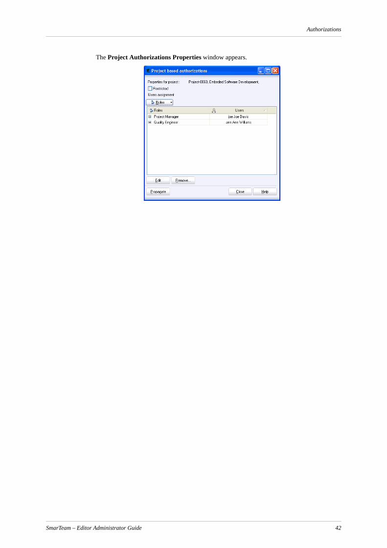
Authorizations
The Project Authorizations Properties window appears.
SmarTeam – Editor Administrator Guide 42
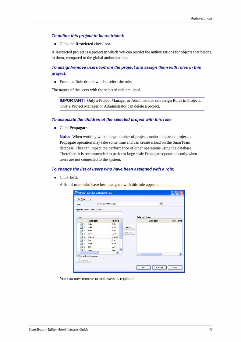
Authorizations
To define this project to be restricted:
Click the Restricted check box.
A Restricted project is a project in which you can restrict the authorizations for objects that belong to them, compared to the global authorizations.
To assign/remove users to/from the project and assign them with roles in this project:
From the Role dropdown list, select the role.
The names of the users with the selected role are listed.
IMPORTANT! Only a Project Manager or Administrator can assign Roles in Projects. Only a Project Manager or Administrator can delete a project.
To associate the children of the selected project with this role:
Click Propagate.
Note: When working with a large number of projects under the parent project, a Propagate operation may take some time and can create a load on the SmarTeam database. This can impact the performance of other operations using the database. Therefore, it is recommended to perform large scale Propagate operations only when users are not connected to the system.
To change the list of users who have been assigned with a role:
Click Edit.
A list of users who have been assigned with this role appears.
You can now remove or add users as required.
SmarTeam – Editor Administrator Guide 43

Authorizations
Adding the User Authorization Report Utility OptionIn order to understand why s/he cannot perform an operation on an object, each user can produce a list of object authorizations.
In order to allow a user to view the object authorization report, the system administrator adds the Object Authorization Report option to the menu that appears when the right mouse button is clicked.
To add the user authorization report option to the menu:
1 From the Tools Menu, select Menu Editor.
2 From the Menu Editor, select Menu Profiles, System Profiles, Choose Profile to update.
3 Insert the new menu item in the desired location with the command std.ObjectAuthorizationReport. For details on how to add an item to a menu, see Menu Editor.
4 Save the changed profiles.
Viewing the Object Authorization Report The Object Authorization Report allows a user to view the authorizations given to him/her per object in the system. A system administrator can view all the all authorations give to all users in the system.
To view the Object Authorization Report:
1 Choose the desired object.
2 Right click and from the menu, select Object Authorization Report.
The report is displayed. For each object, the authorization state and the role/group/project role from which the user received the authorization is shown.
A sample Object Authorization Report is presented below:
SmarTeam – Editor Administrator Guide 44
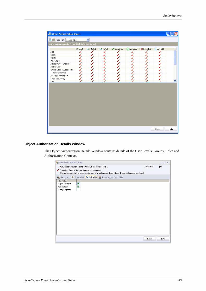
Authorizations
Object Authorization Details Window
The Object Authorization Details Window contains details of the User Levels, Groups, Roles and Authorization Contexts
SmarTeam – Editor Administrator Guide 45
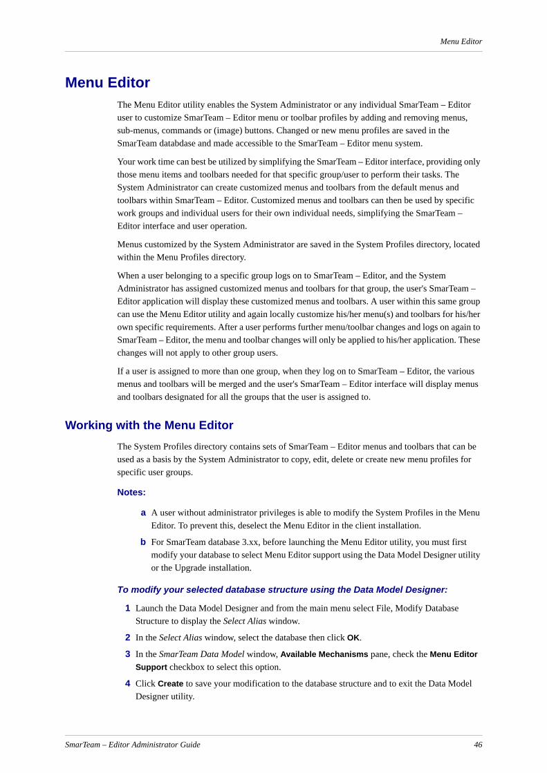
Menu Editor
Menu EditorThe Menu Editor utility enables the System Administrator or any individual SmarTeam – Editor user to customize SmarTeam – Editor menu or toolbar profiles by adding and removing menus, sub-menus, commands or (image) buttons. Changed or new menu profiles are saved in the SmarTeam databdase and made accessible to the SmarTeam – Editor menu system.
Your work time can best be utilized by simplifying the SmarTeam – Editor interface, providing only those menu items and toolbars needed for that specific group/user to perform their tasks. The System Administrator can create customized menus and toolbars from the default menus and toolbars within SmarTeam – Editor. Customized menus and toolbars can then be used by specific work groups and individual users for their own individual needs, simplifying the SmarTeam – Editor interface and user operation.
Menus customized by the System Administrator are saved in the System Profiles directory, located within the Menu Profiles directory.
When a user belonging to a specific group logs on to SmarTeam – Editor, and the System Administrator has assigned customized menus and toolbars for that group, the user's SmarTeam – Editor application will display these customized menus and toolbars. A user within this same group can use the Menu Editor utility and again locally customize his/her menu(s) and toolbars for his/her own specific requirements. After a user performs further menu/toolbar changes and logs on again to SmarTeam – Editor, the menu and toolbar changes will only be applied to his/her application. These changes will not apply to other group users.
If a user is assigned to more than one group, when they log on to SmarTeam – Editor, the various menus and toolbars will be merged and the user's SmarTeam – Editor interface will display menus and toolbars designated for all the groups that the user is assigned to.
Working with the Menu EditorThe System Profiles directory contains sets of SmarTeam – Editor menus and toolbars that can be used as a basis by the System Administrator to copy, edit, delete or create new menu profiles for specific user groups.
Notes:
a A user without administrator privileges is able to modify the System Profiles in the Menu Editor. To prevent this, deselect the Menu Editor in the client installation.
b For SmarTeam database 3.xx, before launching the Menu Editor utility, you must first modify your database to select Menu Editor support using the Data Model Designer utility or the Upgrade installation.
To modify your selected database structure using the Data Model Designer:
1 Launch the Data Model Designer and from the main menu select File, Modify Database Structure to display the Select Alias window.
2 In the Select Alias window, select the database then click OK.
3 In the SmarTeam Data Model window, Available Mechanisms pane, check the Menu Editor Support checkbox to select this option.
4 Click Create to save your modification to the database structure and to exit the Data Model Designer utility.
SmarTeam – Editor Administrator Guide 46

Menu Editor
You can now proceed to launch the Menu Editor utility.
Launching the Menu Editor
To launch the Menu Editor utility:
1 From the SmarTeam – Editor main menu select Tools, Admin Console, User Interface Management, Menu Editor or from the Start button select Programs, SmarTeam, Administrative Tools, Admin Console, Menu Editor.
2 The SmarTeam Login window appears. Enter your User name and Password, if necessary then click OK for your entries to be accepted and to close the window.
3 After successful login, the Menu Editor window opens.
The Menu Editor window contains two separate panes. The left pane displays the Editor Tree, and the right pane displays the directory, menu or toolbar icon, depending on the selection in the Editor Tree.
The Editor Tree can be hidden by clicking in the top right of the Editor Tree pane. To display the Editor Tree, select View, Editor Tree from the main menu. When selected, a tick sign appears next to the menu command, indicating that the Editor Tree is displayed.
By default the Editor Tree pane contains the following folders:
Menu Profiles
Menu Commands
Menu Contexts
The Menu Profiles folder contains two folders, System Profiles and Private Profiles.
The System Profiles folder contains by default tree profiles Administrator, System and User, containing defined SmarTeam – Editor sample menus and toolbars.
IMPORTANT! The System and User profiles provide default menu structures and should not be changed.
Notes:
The Administrator menu profile under the System Profiles is used by the users assigned to the Admin group.
The System menu profile under the System Profiles is used for a user with the Admin function (as defined in User Maintenance) as a default profile menu.
The User menu profile under the System Profiles is used for a user who is not assigned to any group as a default profile menu.
Any default System menu profile can be copied and used as a basis for the newly created customer system menu profile.
Adding a New Product
To add a new product to the System folder:
From the System option, right-click and select Add Product, New Product.
The New Product window appears:
SmarTeam – Editor Administrator Guide 47
Menu Editor
Customizing the SmarTeam – Editor Main MenuScenario: It has been decided to add a new System Profile with specific menu items for Engineering group users. The System Administrator now proceeds to add a new System Profile as described below. Once this new profile has been added, the menus and toolbars can be changed for the new specific groups (in this scenario for the Engineering group).
To carry out this scenario, the System Administrator will need to perform the following:
Add a new System Profile (named Engineering) using the Admin folder as a basis.
Edit the newly-created System Profile.
Define user groups.
Save the new System Profile.
To customize the SmarTeam – Editor main menu for a specific group(s), commence by adding a new System Profile.
IMPORTANT! The following conditions apply when defining menu items in the Menu Editor:
The OpenProductView menu command is enabled only for SmarTeam objects of classes that support "Product" or "Item Behavior" class behaviors
The OpenRevisionsView menu command is enabled only for the revision-managed object’s classes
The OpenSeparateView menu command is NOT enabled in the tree pane of the SmarTeam – Editor main screen.
SmarTeam – Editor Administrator Guide 48

Menu Editor
Due to these conditions, certain changes made in the Menu Editor may not be seen in SmarTeam – Editor.
Adding a New System Profile
To add a new System Profile:
1 In the Editor Tree pane right click on the Admin folder and from the popup menu select Copy.
2 In the Editor Tree pane right click on the System Profiles folder then select Paste, Tree to paste the copied folder and all its contents from the Admin folder in to a new System Profiles folder.
This new folder will automatically be placed in the System Profiles tree and renamed Admin1. The new profile name appears in red to indicate that it has not yet been saved.
3 Right click on Admin1 and select Edit from the popup menu, to display the std.System1 Properties window.
SmarTeam – Editor Administrator Guide 49

Menu Editor
4 Complete the fields as follows:
Caption: Enter Engineering for the Profile's display name that will be displayed in the Editor Tree pane.
Note: The Caption name may be in English characters only.
Internal name: Enter a suitable name for the new profile (e.g, Engineering). Only use letters and/or numbers (not special characters or spaces, such as /?\-*#@ etc.). This entry is used by SmarTeam to identify and access this particular profile.
Groups: Click on the Select… button to display the Profile Groups Window.
5 In the Profile Groups window, select Engineer as the User Group from the All groups list and click Add to add the selected Group to the Groups linked to profile list.
6 To remove a User Group from the Groups linked to profile list, select the User Group then click Remove. The selected User Group is not deleted but just removed to the All groups list. (User Groups can be added or removed at any time by editing this System Profile.)
7 In the Profile Groups window, click OK for your changes to be accepted – or click Cancel to abort any changes made – and to return to the std.System1 Properties window. The User Group, Engineer, selected from the Profile Groups window is now listed in the Groups pane.
8 In the std.System1 Properties window:
Click Apply for your entries to be accepted in the Menu Editor. Note that if you decide at this stage not to continue with this new profile, clicking Cancel will not remove it from the Menu Editor. To remove this new profile, you will need to use the Delete option. (Refer to Deleting Menus/Toolbars for further details.)
Click OK for your entries to be accepted in the Menu Editor and exit the std.System1 Properties window or click Cancel to abort any changes made.
9 After clicking Apply or OK in the std.System1 Properties window, the menus and toolbars copied from the Admin folder will appear in the new System Profile folder named Engineering.
You can now proceed to add new menus or toolbars, edit or delete the existing menus or toolbars for the Engineering user group.
10 In the Editor Tree pane, right click on the new System Profile, Engineering, and select Save from the popup menu, or from the main menu select File, Save all Profiles to save your changes. After the save is complete, the Engineering System Profile name will now appear in black text.
SmarTeam – Editor Administrator Guide 50

Menu Editor
Profile Groups Window
In the Profile Groups window, the All groups pane lists the available User Groups. The Groups linked to profile pane lists selected User Groups that will be affected by these System Profile menus after they have been created.
Adding a User’s Group to the Menu Profile
To add a user's group to the menu profile:
1 From the Admin Console, open Menu Editor.
2 From the Smart Menus, select Menu Profiles, System Profiles.
3 Select "System" Or "User" profile, right-click and select Edit.
4 From the General tab, click "Select " to add a group link to the profile.
Note: Verify that the user is a member of that specific group.
5 Click OK and then click OK again.
6 From the menu, select "File" and then select "Save Profile".
Toolbar Manager Window
Toolbars
Click on the Toolbars tab to display a list of available toolbars that can be selected to automatically display in the SmarTeam – Editor Toolbar:
Select and click in a toolbar's checkbox to display the toolbar. When selected, a checkmark is displayed.
To hide a toolbar, click in the applicable checkbox to remove the checkmark.
Options
Click on the Options tab to display the following option:
Show Screen Tips on Toolbars
When this option is checked, screen tips are displayed for toolbar icons.
When you place your cursor over an icon, a brief description is displayed for the selected icon.
Click OK to save any changes made and close the window.
SmarTeam – Editor Administrator Guide 51
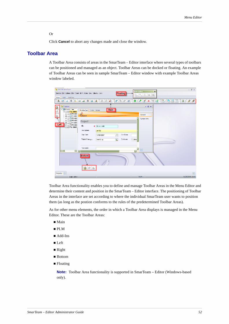
Menu Editor
Or
Click Cancel to abort any changes made and close the window.
Toolbar AreaA Toolbar Area consists of areas in the SmarTeam – Editor interface where several types of toolbars can be positioned and managed as an object. Toolbar Areas can be docked or floating. An example of Toolbar Areas can be seen in sample SmarTeam – Editor window with example Toolbar Areas window labeled.
Toolbar Area functionality enables you to define and manage Toolbar Areas in the Menu Editor and determine their content and position in the SmarTeam – Editor interface. The positioning of Toolbar Areas in the interface are set according to where the individual SmarTeam user wants to position them (as long as the postion conforms to the rules of the predetermined Toolbar Areas).
As for other menu elements, the order in which a Toolbar Area displays is managed in the Menu Editor. These are the Toolbar Areas:
Main
PLM
Add-Ins
Left
Right
Bottom
Floating
Note: Toolbar Area functionality is supported in SmarTeam – Editor (Windows-based only).
SmarTeam – Editor Administrator Guide 52
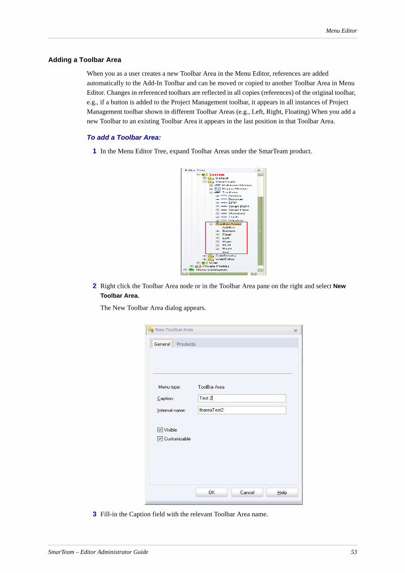
Menu Editor
Adding a Toolbar Area
When you as a user creates a new Toolbar Area in the Menu Editor, references are added automatically to the Add-In Toolbar and can be moved or copied to another Toolbar Area in Menu Editor. Changes in referenced toolbars are reflected in all copies (references) of the original toolbar, e.g., if a button is added to the Project Management toolbar, it appears in all instances of Project Management toolbar shown in different Toolbar Areas (e.g., Left, Right, Floating) When you add a new Toolbar to an existing Toolbar Area it appears in the last position in that Toolbar Area.
To add a Toolbar Area:
1 In the Menu Editor Tree, expand Toolbar Areas under the SmarTeam product.
2 Right click the Toolbar Area node or in the Toolbar Area pane on the right and select New Toolbar Area.
The New Toolbar Area dialog appears.
3 Fill-in the Caption field with the relevant Toolbar Area name.
SmarTeam – Editor Administrator Guide 53

Menu Editor
4 The Visible checkbox appears selected by default, clear the Visible checkbox if you want the new Toolbar Area to be invisible.
5 The Customizable checkbox appears selected by default, clear the Customizable checkbox if you do not want the option to customize theToolbar Area.
6 Click OK.
The new Toolbar Area is added.
Editing a Toolbar Area
To edit an existing Toolbar Area:
1 In the Editor tree, select the Toolbar Area you want to edit.
2 Right click and select Edit.
The <Name> Properties dialog for the selected Toolbar Area appears.
3 Edit the relevant Toolbar Area and click OK.
Deleting a Toolbar Area
If a Toolbar Area contains the last reference of the toolbar, the toolbar will be moved in the Add-Inn Toolbar Area.
To delete a Toolbar Area:
1 In the Editor tree, select the Toolbar Area you want to delete.
2 Right click and select Delete.
Linking a Toolbar to a Toolbar Area
Note: In the Toolbar Properties dialog, a Toolbar Areas tab presents a Toolbar Areas list per Product, e.g., SmarTeam – Editor (Windows based). Each Product name and its corresponding Toolbar Area appear as the root of the branch in the Menu Editor tree.
To link a Toolbar to a Toolbar Area:
1 In the Menu Editor Tree, expand Toolbar. under the SmarTeam product.
2 Select the Toolbar (e.g., Actions) you want to link to a Toolbar Area, right click and select Edit.
SmarTeam – Editor Administrator Guide 54

Menu Editor
3 In the Actions Properties dialog, Toolbar Area tab, select checkbox of the Toolbar Area to which you want to link the Actions Toolbar (e.g., Floating, Right).
4 Click OK.
To remove a link between a Toolbar and Toolbar Area:
1 Select a toolbar under a specific Toolbar Area.
2 In the Actions menu, click Cut.
Deleting Menus/ToolbarsScenario: It has been decided that Engineering group users do not need the following menu commands in the SmarTeam – Editor Tools sub-menu: Language, Language Selection. The System Administrator can now proceed to remove these two menu commands from the Engineering System Profile as described below. Removing these menu commands will only affect the Engineering group and all users assigned to that group.
The Menu Editor provides two methods for removing a menu/toolbar command:
SmarTeam – Editor Administrator Guide 55

Menu Editor
Deleting the menu/toolbar command.
Making the menu/toolbar command invisible to a user without actually deleting the command. This method will make it easier and quicker for the System Administrator to replace it at a later date.
Deleting a Menu/Toolbar Command
To delete a menu command from a System Profile sub-menu:
1 In the Menu Editor window, in the Editor Tree pane, select the Engineering System Profile folder and expand it.
2 Click on the SmarTeam icon to expand it then click and expand the Pulldown Menus icon to display the SmarTeam – Editor Main Menu icon. Click and expand the SmarTeam – Editor Main Menu icon and select the sub-menu that contains the item(s) that you want to delete – in this case, Tools.
To show command item details in the right pane:
1 From the main menu select View, Details
OR
In the Menu Editor toolbar select Views and click on the dropdown arrow and select Details.
2 To delete the first menu item, Language…, do one of the following:
In the Tree Editor, select and right click on the item Language… then select Delete from the popup menu or in the Menu Editor toolbar click on the Delete button.
OR
In the right pane, select and right click on the item Language… then select Delete from the popup menu or in the Menu Editor toolbar click on the Delete button.
3 The SmarTeam message window is now displayed, prompting you to confirm your request to delete the selected menu item. Click Yes to continue and delete the menu item or click No to abort deleting the menu item.
4 To delete the second menu item, repeat the above steps to delete Language Selection from the selected sub-menu.
Making a Menu/Toolbar Command Invisible
To remove the menu commands from Engineering group users by making it invisible:
1 Repeat steps 1- 2 in Deleting Menus/Toolbars.
2 In the Tree Editor, select and right click on the item Language… then select Edit from the popup menu to display the mniLanguage Properties window.
3 In the mniLanguage Properties window click in the checked Visible and Customizable checkboxes to uncheck these options.
When a defined user in the Engineering group logs on to SmarTeam – Editor, the Language… menu command will no longer appear in the Tools dropdown menu, nor will the user be able to edit this menu item.
SmarTeam – Editor Administrator Guide 56

Menu Editor
4 In the mniLanguage Properties window, click OK for your entries to be accepted in the Menu Editor and exit the mniLanguage Properties window or click Cancel to abort any changes made.
5 Repeat the above steps for the second menu item, Language Selection.
Adding a New Menu Item to a Sub-MenuScenario: It has now been decided to add a new menu item named General Link to the SmarTeam View dropdown menu for the Engineering group. This menu item will be added as the first item in the View dropdown menu and will display general links for a selected object.
To add the new (command) menu to the View sub-menu:
1 In the Editor Tree, click on Engineering to expand it.
2 Click on the SmarTeam icon to expand it then click and expand the Pulldown Menus icon to display the SmarTeam – Editor Main Menu icon. Click and expand the SmarTeam – Editor Main Menu icon.
3 Click on the View icon to expand it, displaying all the menu items for the View dropdown menu. Two options are available for adding a new item, as follows:
New Menu Item: Adds a new menu item at the end of the existing sub-menu items.
Insert New Menu Item: Adds a new menu item directly above the selected sub-menu item.
4 Right click on the View icon and select New Menu Item from the popup menu to display the New Menu Item window.
5 In the New Menu Item window complete the following fields:
Menu item type
For this scenario, select Command Item to add the new menu item directly to the View dropdown menu.
Internal name
Enter General Links as a name for the new menu item. Only use letters and/or numbers (not special characters or spaces, such as /?\-*#@ etc.).This entry is used by SmarTeam to identify and access this particular menu item.
Caption
Enter General Links as a suitable caption for the menu item. This is the actual name of the new menu item that will appear in the SmarTeam View dropdown menu.
Note: The Caption name may be in English characters only.
Menu Type Description
Command Item Enables the Command field for defining a command for this menu.
SubMenu Item Enables sub-menu items to be created.
Separator Enables a separator to be added between menu items. When you select this menu type, all other fields are not enabled. Proceed to the next step to exit from the New Item window.
SmarTeam – Editor Administrator Guide 57
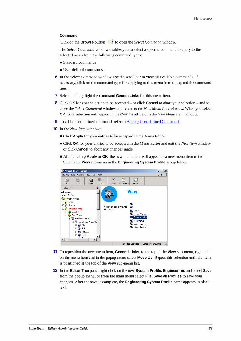
Menu Editor
Command
Click on the Browse button to open the Select Command window.
The Select Command window enables you to select a specific command to apply to the selected menu from the following command types:
Standard commands
User-defined commands
6 In the Select Command window, use the scroll bar to view all available commands. If necessary, click on the command type for applying to this menu item to expand the command tree.
7 Select and highlight the command GeneralLinks for this menu item.
8 Click OK for your selection to be accepted – or click Cancel to abort your selection – and to close the Select Command window and return to the New Menu Item window. When you select OK, your selection will appear in the Command field in the New Menu Item window.
9 To add a user-defined command, refer to Adding User-defined Commands.
10 In the New Item window:
Click Apply for your entries to be accepted in the Menu Editor.
Click OK for your entries to be accepted in the Menu Editor and exit the New Item window or click Cancel to abort any changes made.
After clicking Apply or OK, the new menu item will appear as a new menu item in the SmarTeam View sub-menu in the Engineering System Profile group folder.
11 To reposition the new menu item, General Links, to the top of the View sub-menu, right click on the menu item and in the popup menu select Move Up. Repeat this selection until the item is positioned at the top of the View sub-menu list.
12 In the Editor Tree pane, right click on the new System Profile, Engineering, and select Save from the popup menu, or from the main menu select File, Save all Profiles to save your changes. After the save is complete, the Engineering System Profile name appears in black text.
SmarTeam – Editor Administrator Guide 58

Menu Editor
Adding User-defined CommandsIn addition to the default Standard commands that are available for attaching to menus to perform a defined action, the System Administrator or individual user can define his/her own commands for attaching to menus.
User-defined commands can be created using the SmarTeam utility, User-defined Tools, accessed from the Actions sub-menu in the SmarTeam – Editor main menu.
User-defined command(s) are first added to the Menu Editor Commands folder and can then be selected and added to menu commands.
To add a user-defined command to the Menu Editor Commands folder:
1 In the Editor Tree, click on the Commands folder to expand it then select User-defined Commands.
2 In the Menu Commands folder, right click User-defined Commands and select New User-defined Commands from the popup menu, to display the New User-defined Command window.
3 In the New User-defined Command window, click on the General tab to display the New User-defined Command General page (if not already displayed):
4 Complete the following fields:
Caption
The Command's display name that will be displayed in the Editor Tree pane.
Note: The Caption name may be in English characters only.
Internal name
This field is completed automatically when you complete the Internal Name field. If necessary, you can change the name by typing a new name in the field. Only use letters and/or numbers (not special characters or spaces, such as /?\-*#@ etc.).This entry is used by SmarTeam to identify and access this particular command.
User Script
Click on the Browse button to open the Select User-defined Script window, and select the user-defined script that you want to add to the User-defined commands folder.
5 Click OK for your selection to be accepted – or click Cancel to abort your selection – to close the Select User-defined Script window and return to the New User-defined Command window.
When you select OK, your selection will appear in the User-defined commands folder in the Editor Tree pane.
6 In the New User-defined Command window, click on the Contexts tab to display the New User-defined Command Contexts page.
Context settings define user positioning, such as when a selected SmarTeam function is active it will be possible to select this item. (Context settings enable commands to be performed on an available selected object.)
SmarTeam – Editor Administrator Guide 59

Menu Editor
Positive Contexts
To define the circumstances under which a command will be available to a selected object:
1 In the Positive Contexts section, click Add… to open the Select Contents window.
2 To add a SmarTeam internal context, select and expand the Internal contexts tree (if not already expanded) to view a list of all the internal contexts provided by SmarTeam – Editor.
3 Check the applicable context checkboxes that you want to apply (as a positive context) to this command.
4 The Custom contexts tree contains contexts that have been added to the Menu Editor using the Custom Context option. To add a custom context, select and expand the Custom contexts tree to view the custom contexts added to the Menu Editor. Check the applicable contexts checkboxes that you want to apply (as a positive context) to this command.
5 Click OK for your changes to be accepted – or click Cancel to abort any changes made – and return to the New User-defined Command window.
Negative Contexts
To define under which circumstances a menu command will not be available to a selected object (in this case, on the user-defined command):
1 In the Negative Contexts section, click Add… to open the Select Contents window.
2 To add a SmarTeam internal context, select and expand the Internal contexts tree to view the internal contexts provided by SmarTeam – Editor.
3 Check the applicable contexts checkboxes that you want to apply (as a negative context) to this command.
4 The Custom contexts tree contains contexts that have been added to the Menu Editor using the Custom Context option. To add a custom context, select and expand the Custom contexts tree to view the custom contexts added to the Menu Editor. Check the applicable contexts checkboxes that you want to apply (as a negative context) to this command.
5 Click OK for your changes to be accepted – or click Cancel to abort any changes made – and return to the New User-defined Command window.
The New User-defined Command window shows both positive and negative contexts (when added) that will be applied for this command.
Removing a Context
To remove a context from the selected menu item:
Select and highlight the context then click Remove.
Attaching an Icon to the Selected Command1 In the New User-defined Command window, click on the Icon tab to display the New User-
defined Command Icon page.
The New User-defined Command Icon page enables you to select an icon to attach an image to the selected (command) item that will appear alongside the selected menu item.
2 Click on the Select icon… button to open a standard Windows Open window.
SmarTeam – Editor Administrator Guide 60

Menu Editor
The SmarTeam Icons directory will open by default, allowing you to select an applicable icon for the selected command, or you can browse to a different directory to select from other icons.
3 In the Open window, click Open to add the selected icon to the New User-defined Command Icon page.
The Icon Name field indicates the selected icon name.
The Folder field indicates the location of the selected icon file.
4 To remove a selected icon, click on the Delete button or simply select another icon from the SmarTeam Icons directory.
5 In the New User-defined Command window, click on the Products tab to display the New User-defined Command Products page.
6 In the Products page, check the applicable checkbox for the integration product for defining this command.
7 In the New User-defined Command window:
Click Apply at any time for your entries to be accepted in the Menu Editor.
Click OK for your entries to be accepted in the Menu Editor and exit the New User-defined Command window.
OR
Click Cancel to abort any changes made.
After clicking OK, the new user-defined command will appear in the User-defined commands folder and can be selected to add to a menu item.
Editing User-defined Commands
To edit a user-defined command in the Menu Editor Commands folder:
1 In the Editor Tree, click on the Commands folder to expand it then select User-defined Commands.
2 Click on the User-defined Commands icon to expand it. Right click on the command that you want to edit and select Edit from the popup menu, to display the [Defined Command] Properties window.
3 Make your changes in the [Defined Command] Properties window, as necessary. Refer to Adding User-defined Commands for a description of the [Defined Command] Properties window.
4 After making all necessary changes, in the [Defined Command] Properties window click OK for your changes to be accepted – or click Cancel to abort any changes made – and to return to the Menu Editor.
Deleting User-defined Commands
To delete a user-defined command in the Menu Editor Commands folder:
1 In the Editor Tree, click on the Commands folder to expand it then select User-defined Commands.
2 Click on the User-defined Commands icon to expand it. Right click on the command that you want to delete and select Delete from the popup menu.
SmarTeam – Editor Administrator Guide 61
Menu Editor
3 The SmarTeam – Editor message window is now displayed, prompting you to confirm your request to delete the selected command item. Click Yes to continue and delete the command item or click No to abort deleting the command item
Saving in the Menu EditorAny changes made in the Menu Editor will only take affect in SmarTeam – Editor after saving your changes and exiting the Menu Editor.
Whenever changes are made to a System Profile, the System Profile name will appear in red until all changes have been saved.
To save the changes made to a System Profile:
1 Select the System Profile folder that you want to save changes.
2 Right click on the folder and from the popup menu select Save.
OR
From the Menu Editor main menu select File, Save Profile (Ctrl+S).
3 To save changes that have been made to more than one System Profile at the same time, from the Menu Editor main menu select File, Save All Profiles.
After saving a changed System Profile(s), the profile's name reverts to black text, indicating that all changes have been saved.
4 If you attempt to exit the Menu Profile utility without saving any changes made to a System Profile, a SmarTeam – Editor warning window will appear, prompting you to save your changes.
In the SmarTeam warning window, click Yes to save any changes made to the System Profiles or click No to abort any changes made and to continue exiting the Menu Editor utility. Click Cancel to return to the Menu Editor utility without exiting and without saving any changes made to the System Profiles.
Editing Existing System ProfilesScenario: It has been decided to change the users who can use a specific profile, in this case the Engineering System Profile. In addition, because of this change, the profile name will also be changed to Aero Engineers.
To edit the Engineering System Profile menu:
1 In the Editor Tree, right click on the Engineering System Profile folder and select Edit from the popup menu.
2 The grp.Engineering Properties window opens, allowing you to edit the available fields.
Caption
Enter a new name in this field. When you make an entry in this field it is also automatically entered in the internal name field. Only use letters and/or numbers (not special characters or spaces, such as /?\-*#@ etc.).
Note: The Caption name may be in English characters only.
SmarTeam – Editor Administrator Guide 62

Menu Editor
Internal name
This field does not have to be changed because it is used by SmarTeam – Editor for internal identification.
Groups
Click on the Select… button to display the Profile Groups window.
In the Profile Groups window, add or remove a user group as required to/from the Groups linked to profile pane list. All groups listed in the Groups linked to profile pane will be affected by the System Profile menus.
In the Profile Groups window, click OK for your changes to be accepted – or click Cancel to abort any changes made – and return to the grp.Engineering Properties window. The changed User Groups selected from the Profile Groups window are listed in the Groups pane.
3 In the grp.Engineering Properties window:
Click Apply for your changes to be made in the Engineering System Profile folder.
OR
Click OK for your changes to be made in the Engineering System Profile folder and exit the grp.Engineering Properties window or click Cancel to abort any changes made.
4 After clicking Apply or OK, the new System Profile name will replace the previous name.
In the Editor Tree pane, right click on the Aero Engineers System Profile and select Save from the popup menu, or from the main menu select File, Save all Profiles to save your changes.
After the save is complete, the Aero Engineers System Profile name appears in black text. All users designated to the groups selected in the Profile Groups window, Engineer and Manufacturing, will receive the menus and toolbars listed in the Aero Engineers System Profile folder.
Custom ContextsContext settings define user positioning, such as which SmarTeam – Editor window is active, which entries are selected (if any). Context settings enable commands to be performed on an available selected object. In addition to the default Internal commands that are available for attaching to commands to define a context setting, the System Administrator or individual user can define his/her own context settings for applying to menu commands.
Custom contexts are first created using an API. Once created, a custom context is added to the Menu Editor Contexts folder and can then be selected and added to menu commands.
To add a custom context to the Menu Editor Contexts folder:
1 In the Editor Tree, click on the Contexts folder to expand it and then select Custom Contexts.
2 Right click Custom Contexts and select New Custom Context from the popup menu, to display the New Context window.
SmarTeam – Editor Administrator Guide 63

Menu Editor
3 In the New Context window, complete the fields as follows:
Caption
The custom context's display name that will be displayed in the Editor Tree pane. This field is completed automatically when you complete the Internal Name field. If necessary, you can change the name by typing a new name in the field.
Note: The Caption name may be in English characters only.
Internal name
Enter a suitable name for the new custom context. Only use letters and/or numbers (not special characters or spaces, such as /?\-*#@ etc.).This entry is used by SmarTeam – Editor to identify and access this particular profile.
4 In the New Context window:
Click Apply for your entries to be accepted in the Menu Editor.
OR
Click OK for your entries to be accepted in the Menu Editor and exit the New Context window.
OR
Click Cancel to abort any changes made.
After clicking OK, the new custom context will appear in the Custom contexts folder and can be selected to add to a menu item.
To edit a custom context in the Menu Editor Contexts folder:
1 In the Editor Tree, click on the Contexts folder to expand it and then select Custom Contexts.
2 Click on the Custom Contexts icon to expand it. Right click on the command that you want to edit and select Edit from the popup menu, to display the [Custom Context] Properties window.
3 Make your changes in the [Custom Context] Properties window, as necessary.
SmarTeam – Editor Administrator Guide 64

Menu Editor
4 After making all necessary changes in the [Custom Context] Properties window, click OK for your changes to be accepted – or click Cancel to abort any changes made – and to return to the Menu Editor.
To delete a custom context in the Menu Editor Contexts folder:
1 In the Editor Tree, click on the Contexts folder to expand it and then select Custom Contexts.
2 Click on the Custom Contexts icon to expand it. Right click on the custom context that you want to delete and select Delete from the popup menu.
3 The SmarTeam – Editor message window is now displayed, prompting you to confirm your request to delete the selected context item. Click Yes to continue and delete the context item.
Merging Menu ProfilesThere are cases where a user has more than one menu profile (for example: user is in 2 groups and each group is defined in a different menu profile) they will see the sum of the menu profiles.
The category under which you see a specific menu item is by its internal name:
If the caption of the menu item display name is the same in 2 menu profiles and the internal name of the menu item is different then the user will see this menu item twice.
If the caption of the menu item display name is different in 2 menu profiles and the internal name of the menu item is the same then the user will see this menu item only once.
If the caption of the menu item display name is the same in 2 menu profiles and the internal name of the menu item is the same then the user will see this menu item only once.
Examples:
Menu Item Display Name Menu Item Internal Name Result
Update mniUpdate Update will be seen twice
Update mniUpdateObject
Menu Item Display Name Menu Item Internal Name Result
Update mniUpdate Update will be seen once
Update Object mniUpdate
SmarTeam – Editor Administrator Guide 65
Menu Editor
Upgrading from Previous VersionsPrior to SmarTeam V5R13, the Menu Editor included an optional database level mechanism, which functioned as follows:
When the Menu Editor was disabled, SmarTeam always displayed a hard-coded menu: all user-defined menu items defined by user scripts in Script Maintenance were displayed.
When the Menu Editor was enabled, the SmarTeam administrator could manually add tools to the user-defined menu.
From SmarTeam V5R13, the Menu Editor’s database level mechanism is built-in. All menu items defined by user scripts in the Script Maintenance utility appear automatically in the User Defined menu. If it is necessary to add user-defined tools, the SmarTeam administrator can do this by creating a new menu item and assigning the required tools to this item.
Menu Item Display Name Menu Item Internal Name Result
Update mniUpdate Update will be seen once
Update mniUpdateObject
SmarTeam – Editor Administrator Guide 66
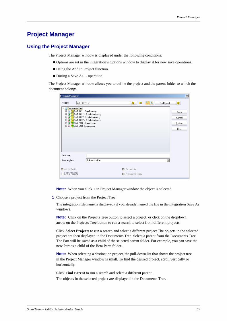
Project Manager
Project Manager
Using the Project ManagerThe Project Manager window is displayed under the following conditions:
Options are set in the integration’s Options window to display it for new save operations.
Using the Add to Project function.
During a Save As… operation.
The Project Manager window allows you to define the project and the parent folder to which the document belongs.
Note: When you click + in Project Manager window the object is selected.
1 Choose a project from the Project Tree.
The integration file name is displayed (if you already named the file in the integration Save As window).
Note: Click on the Projects Tree button to select a project, or click on the dropdown arrow on the Projects Tree button to run a search to select from different projects.
Click Select Projects to run a search and select a different project.The objects in the selected project are then displayed in the Documents Tree. Select a parent from the Documents Tree. The Part will be saved as a child of the selected parent folder. For example, you can save the new Part as a child of the Beta Parts folder.
Note: When selecting a destination project, the pull-down list that shows the project tree in the Project Manager window is small. To find the desired project, scroll vertically or horizontally.
Click Find Parent to run a search and select a different parent.The objects in the selected project are displayed in the Documents Tree.
SmarTeam – Editor Administrator Guide 67
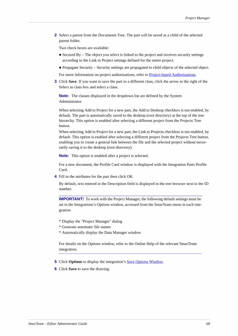
Project Manager
2 Select a parent from the Documents Tree. The part will be saved as a child of the selected parent folder.
Two check boxes are available:
Secured By – The object you select is linked to the project and receives security settings according to the Link to Project settings defined for the entire project.
Propagate Security – Security settings are propagated to child objects of the selected object.
For more information on project authorizations, refer to Project-based Authorizations.
3 Click Save. If you want to save the part to a different class, click the arrow to the right of the Select as class box and select a class.
Note: The classes displayed in the dropdown list are defined by the System Administrator.
When selecting Add to Project for a new part, the Add to Desktop checkbox is not enabled, by default. The part is automatically saved to the desktop (root directory) at the top of the tree hierarchy. This option is enabled after selecting a different project from the Projects Tree button.When selecting Add to Project for a new part, the Link to Projects checkbox is not enabled, by default. This option is enabled after selecting a different project from the Projects Tree button, enabling you to create a general link between the file and the selected project without neces-sarily saving it to the desktop (root directory).
Note: This option is enabled after a project is selected.
For a new document, the Profile Card window is displayed with the Integration Parts Profile Card.
4 Fill in the attributes for the part then click OK.
By default, text entered in the Description field is displayed in the tree browser next to the ID number.
IMPORTANT! To work with the Project Manager, the following default settings must be set in the Integrations’s Options window, accessed from the SmarTeam menu in each inte-gration:
* Display the "Project Manager" dialog* Generate automatic file names* Automatically display the Data Manager window
For details on the Options window, refer to the Online Help of the relevant SmarTeam integration.
5 Click Options to display the integration’s Save Options Window.
6 Click Save to save the drawing.
SmarTeam – Editor Administrator Guide 68
Project Manager
Save Options WindowThe Save Options window contains two tabs:
Save Tab
Tree Setting Tab
Save Tab
This tab contains the following check boxes:
Batch Save ModeSelect this checkbox if you do not want a Profile Card displayed when saving a new CAD file into the SmarTeam database. (This option is not checked by default.)
Display the "Project Manager" Dialog for save This option, to display the Project Manager window when saving a new CAD file into the SmarTeam database, is checked by default. To uncheck this option, click once in the checkbox.
Note: If you defined a default project and/or a default parent, these defaults are automat-ically selected in the Project Manager window.
Tree Setting Tab
This tab allows you to define the level of sub-branches displayed in the project selection tree and/or the object selection tree. Note that if you choose to display lower levels, this will effect your speed.
This tab contains the following check boxes:
Expand Level of Project TreeClick on the up or down arrows to define the level of branches that will be displayed in the Project Tree.
Expand Level of Objects TreeClick on the up or down arrows to define the level of branches that will be displayed in the Object Tree.
Configuring the Project Manager Window
To enable the SmarTeam Project Manager window to appear, perform the following steps:
1 Open the SmarTeam System Configuration Utility.
2 Search for the key “[Application]. ShowSaveAsDialog”. where [Application] is the relevant application, e.g., AutoCAD or Autodesk Mechanical Desktop. The configuration set and key name are displayed.
3 Click on the key name. The values of the key for various override levels are displayed.
4 If the value is not YES, click on the value in the appropriate override level and change it to YES. Repeat for other desired override levels.
SmarTeam – Editor Administrator Guide 69
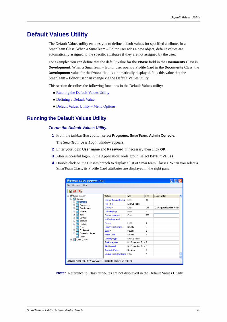
Default Values Utility
Default Values UtilityThe Default Values utility enables you to define default values for specified attributes in a SmarTeam Class. When a SmarTeam – Editor user adds a new object, default values are automatically assigned to the specific attributes if they are not assigned by the user.
For example: You can define that the default value for the Phase field in the Documents Class is Development. When a SmarTeam – Editor user opens a Profile Card in the Documents Class, the Development value for the Phase field is automatically displayed. It is this value that the SmarTeam – Editor user can change via the Default Values utility.
This section describes the following functions in the Default Values utility:
Running the Default Values Utility
Defining a Default Value
Default Values Utility – Menu Options
Running the Default Values Utility
To run the Default Values Utility:
1 From the taskbar Start button select Programs, SmarTeam, Admin Console.
The SmarTeam User Login window appears.
2 Enter your login User name and Password, if necessary then click OK.
3 After successful login, in the Application Tools group, select Default Values.
4 Double click on the Classes branch to display a list of SmarTeam Classes. When you select a SmarTeam Class, its Profile Card attributes are displayed in the right pane.
Note: Reference to Class attributes are not displayed in the Default Values Utility.
SmarTeam – Editor Administrator Guide 70

Default Values Utility
Defining a Default Value
To define a default value:
1 In the Default Values window, select a SmarTeam Class. The Profile Card attributes for the selected Class are displayed in the right pane.
2 In the Default Value column, enter the default value to define the selected attribute.
3 From the File menu, click Save to save these values in the SmarTeam database.
Default Values Utility – Menu Options
File Menu
Options Menu
Default Values Utility - ToolbarThe Default Values Utility toolbar contains the following options:
Option Description
Save Saves the defined values to the SmarTeam database.
Save to File Enables you to save these values to a text file. A Standard File Selection window is displayed. Select a file.
Exit Exits the program.
Option Description
Attribute Display Mode
Enables you to change the displayed view of the SmarTeam attributes. This option contains two sub-options:
Column Name Displays the column name of the attributes.
Display Name Displays the display name of the attributes as defined in the Data Model Wizard.
Option Description
Save Saves the defined values to the SmarTeam database.
Set current as inherited
Takes the definition of this attribute from the parent class
Save to File Enables you to save these values to a text file. A Standard File Selection window is displayed. Define a file.
SmarTeam – Editor Administrator Guide 71
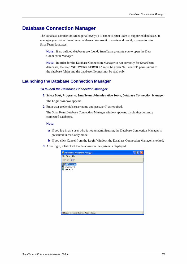
Database Connection Manager
Database Connection ManagerThe Database Connection Manager allows you to connect SmarTeam to supported databases. It manages your list of SmarTeam databases. You use it to create and modify connections to SmarTeam databases.
Note: If no defined databases are found, SmarTeam prompts you to open the Data Connection Manager.
Note: In order for the Database Connection Manager to run correctly for SmarTeam databases, the user "NETWORK SERVICE" must be given "full control" permissions to the database folder and the database file must not be read only.
Launching the Database Connection Manager
To launch the Database Connection Manager:
1 Select Start, Programs, SmarTeam, Administrative Tools, Database Connection Manager.
The Login Window appears.
2 Enter user credentials (user name and password) as required.
The SmarTeam Database Connection Manager window appears, displaying currently connected databases.
Note:
a If you log in as a user who is not an administrator, the Database Connection Manager is presented in read-only mode.
b If you click Cancel from the Login Window, the Database Connection Manager is exited.
3 After login, a list of all the databases in the system is displayed.
SmarTeam – Editor Administrator Guide 72
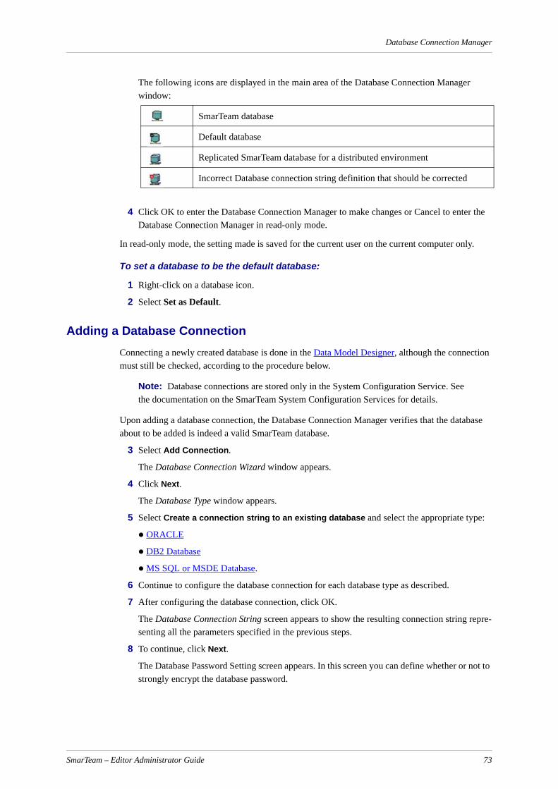
Database Connection Manager
The following icons are displayed in the main area of the Database Connection Manager window:
4 Click OK to enter the Database Connection Manager to make changes or Cancel to enter the Database Connection Manager in read-only mode.
In read-only mode, the setting made is saved for the current user on the current computer only.
To set a database to be the default database:
1 Right-click on a database icon.
2 Select Set as Default.
Adding a Database ConnectionConnecting a newly created database is done in the Data Model Designer, although the connection must still be checked, according to the procedure below.
Note: Database connections are stored only in the System Configuration Service. See the documentation on the SmarTeam System Configuration Services for details.
Upon adding a database connection, the Database Connection Manager verifies that the database about to be added is indeed a valid SmarTeam database.
3 Select Add Connection.
The Database Connection Wizard window appears.
4 Click Next.
The Database Type window appears.
5 Select Create a connection string to an existing database and select the appropriate type:
ORACLE
DB2 Database
MS SQL or MSDE Database.
6 Continue to configure the database connection for each database type as described.
7 After configuring the database connection, click OK.
The Database Connection String screen appears to show the resulting connection string repre-senting all the parameters specified in the previous steps.
8 To continue, click Next.
The Database Password Setting screen appears. In this screen you can define whether or not to strongly encrypt the database password.
SmarTeam database
Default database
Replicated SmarTeam database for a distributed environment
Incorrect Database connection string definition that should be corrected
SmarTeam – Editor Administrator Guide 73
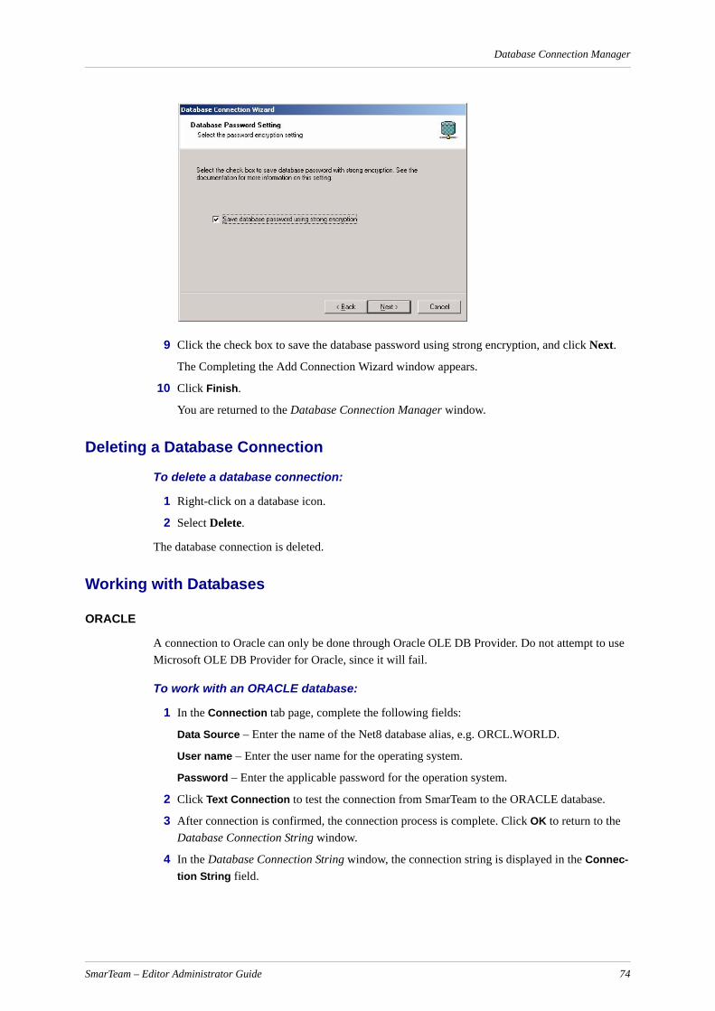
Database Connection Manager
9 Click the check box to save the database password using strong encryption, and click Next.
The Completing the Add Connection Wizard window appears.
10 Click Finish.
You are returned to the Database Connection Manager window.
Deleting a Database Connection
To delete a database connection:
1 Right-click on a database icon.
2 Select Delete.
The database connection is deleted.
Working with Databases
ORACLE
A connection to Oracle can only be done through Oracle OLE DB Provider. Do not attempt to use Microsoft OLE DB Provider for Oracle, since it will fail.
To work with an ORACLE database:
1 In the Connection tab page, complete the following fields:
Data Source – Enter the name of the Net8 database alias, e.g. ORCL.WORLD.
User name – Enter the user name for the operating system.
Password – Enter the applicable password for the operation system.
2 Click Text Connection to test the connection from SmarTeam to the ORACLE database.
3 After connection is confirmed, the connection process is complete. Click OK to return to the Database Connection String window.
4 In the Database Connection String window, the connection string is displayed in the Connec-tion String field.
SmarTeam – Editor Administrator Guide 74
Database Connection Manager
DB2 Database
To work with a DB2 database:
1 In the Connection tab page, complete the following fields:
Data Source – Enter the name of the database alias, e.g. SMARTDB.
User name – Enter the user name for the operating system.
Password – Enter the applicable password for the operation system.
2 Click Text Connection to test the connection from SmarTeam to the DB2 database.
3 After connection is confirmed, the connection process is complete. Click OK to return to the Database Connection String window.
4 In the Database Connection String window, the connection string is displayed in the Connec-tion String field.
MS SQL or MSDE Database
To work with an MS SQL or MSDE database:
1 In the Connection tab page, complete the following fields:
ServerUsernamePasswordDatabase Name
2 Click Text Connection to test the connection from SmarTeam to the SQL database.
Note: This option applies to connecting to databases that are already attached to the database server. Be sure to choose the Select the database on the server and not the Attach a database file as a database name radio button at this point. If you want to use an MSDE or MS SQL Server database file (.MDF file), which is not currently attached to the database server, see Attaching and Connecting to an MSDE Database File.
3 After connection is confirmed, the connection process is complete. Click OK to return to the Database Connection String window.
In the Database Connection String window, the connection string is displayed in the Connec-tion String field.
Attaching and Connecting to an MSDE Database FileAn MSDE database is stored in a database file (ending in *.mdf). In order to work with a database file, you must first go through a process known as "attaching" it to the MSDE server. When you perform an Attach operation, you create a logical name for the database file. Once the file is attached, you can connect to the database using the logical name.
To attach and connect to an MSDE database file:
1 From the Database Provider window, select Attach a new MSDE database file to the server and connect to it to connect an MSDE database not yet in the server to both the database server and to SmarTeam.
The Database Server window appears.
SmarTeam – Editor Administrator Guide 75
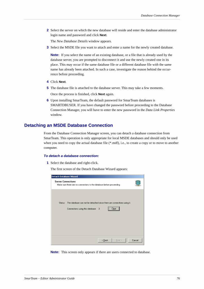
Database Connection Manager
2 Select the server on which the new database will reside and enter the database administrator login name and password and click Next.
The New Database Details window appears.
3 Select the MSDE file you want to attach and enter a name for the newly created database.
Note: If you select the name of an existing database, or a file that is already used by the database server, you are prompted to disconnect it and use the newly created one in its place. This may occur if the same database file or a different database file with the same name has already been attached. In such a case, investigate the reason behind the occur-rence before proceeding.
4 Click Next.
5 The database file is attached to the database server. This may take a few moments.
Once the process is finished, click Next again.
6 Upon installing SmarTeam, the default password for SmarTeam databases is SMARTDBUSER. If you have changed the password before proceeding to the Database Connection Manager, you will have to enter the new password in the Data Link Properties window.
Detaching an MSDE Database ConnectionFrom the Database Connection Manager screen, you can detach a database connection from SmarTeam. This operation is only appropriate for local MSDE databases and should only be used when you need to copy the actual database file (*.mdf), i.e., to create a copy or to move to another computer.
To detach a database connection:
1 Select the database and right-click.
The first screen of the Detach Database Wizard appears:
Note: This screen only appears if there are users connected to database.
SmarTeam – Editor Administrator Guide 76

Database Connection Manager
2 In this screen, the number of users currently connected to this database is shown. When you click Clear, any connected users will be disconnected from the database.
3 Click Next and then Finish.
Database-specific ComponentsThis section provides a technological background for the SmarTeam Database Connection Manager.
SmarTeam uses ADO connectivity to perform the actual operations with a specific vendor database. These components are optimized for a specific database and can take advantage of its unique features, thereby delivering optimal performance.
ADO OLE DB Providers
The database-specific components used by ADO technology are called "OLE DB Providers". The following OLE DB Providers are used:
Oracle database – Oracle OLE DB provider that is supplied by Oracle. From V5R11 onwards, SmarTeam supports Oracle versions 9.2 (9i) and 8.1.7 (8i). For Oracle 8.1.7 the version of server, client and OLE DB provider should be 8.1.7.2 or higher. It is necessary that both client and server installations use the same Oracle version. Please consult SmarTeam support for the latest recommendations.
DB2 database – Use an IBM OLE DB Provider for DB2 supplied by IBM. Currently, SmarTeam supports DB2 version 7.2 FixPack 5 and 8. DB2 version 8.1. DB2 version 7.2 Fix Pack 8 is recommended.
Microsoft SQL Server – Use a Microsoft OLE DB Provider for MS SQL Server version 2000, with respective service packs. This package is part of MDAC (Microsoft Data Access Compo-nents). SmarTeam requires that MDAC 2.7 be installed on the workstation. If its presence is not detected, SmarTeam installs MDAC 2.7 automatically. At present, SP3 for MS SQL Server 2000 is highly recommended. It is installed automatically as a part of regular SmarTeam – Editor installation for MSDE.
Note: SmarTeam V5R11 no longer supports Interbase as a database engine for its demo database. An MSDE (Microsoft Database Engine) is supported instead. It has similar functionality as MS SQL Server, but is restricted to a small number of user connections and has no built-in management tools. It is installed automatically as a part of regular SmarTeam – Editor installation for the MSDE.
TroubleshootingIf a database connection has become corrupt, you might have problems entering the Data Connec-tion Manager. In this case, you can use the Authentication Manager to delete the entire list of databases connected to the system. See Session Management Service for details.
After the list of databases has been deleted, you can enter the Database Connection Manager. (In this case, the login screen will not appear.)
SmarTeam – Editor Administrator Guide 77

Integration Tools Setup
Integration Tools SetupThe Integration Tool Setup Utility enables the Administrator to define relationships between SmarTeam integrations and SmarTeam – Editor. This provides users with the highest level of integration, enabling a bi-directional mapping between any integration and SmarTeam – Editor.
Examples of the type of properties that can be mapped to an integration's attributes are shown below:
Summary Information
Custom Properties
Title Block
Dimensions
Mass Properties
Special Attributes
Revision Block
Properties are mapped from the Mapping Group Tree window. All property types (or group types) for the various integrations are mapped in the same way.
The Integration Tool Setup Utility is used to:
Define new relationships between SmarTeam – Editor and integrations
Add, update and delete mapping groups, mapping properties and mapping attributes.
Terminology
Starting the Integration Tool Setup Utility1 From the taskbar, select Start, Programs, SmarTeam, Admin Console and then Integration
Tools Setup. The Available Databases window opens.
2 In the Available Databases window, select and highlight a database then click OK. The SmarTeam User Login window appears.
3 In the SmarTeam User Login window enter your assigned User Name and Password, if necessary then click OK. The Integration Tool Setup window opens, listing all defined integrations.
In the Integration Tools Setup window, you can select an image to represent a specific integration.
Integration An application that functionally contains SmarTeam data management features.
Properties Definable characteristics, files or objects created by an integration.
Component Types
Major classification elements defined per integration. For example: an integration may support components Items, Assemblies, Drawings. Each component can be defined as a class within SmarTeam – Editor.
SmarTeam – Editor Administrator Guide 78
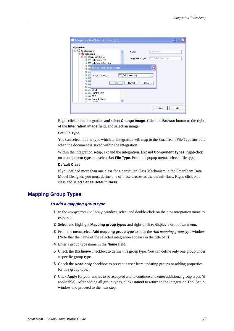
Integration Tools Setup
Right-click on an integration and select Change Image. Click the Browse button to the right of the Integration Image field, and select an image.
Set File Type
You can select the file type which an integration will map to the SmarTeam File Type attribute when the document is saved within the integration.
Within the integration setup, expand the integration. Expand Component Types, right-click on a component type and select Set File Type. From the popup menu, select a file type.
Default Class
If you defined more than one class for a particular Class Mechanism in the SmarTeam Data Model Designer, you must define one of these classes as the default class. Right-click on a class and select Set as Default Class.
Mapping Group Types
To add a mapping group type:
1 In the Integration Tool Setup window, select and double-click on the new integration name to expand it.
2 Select and highlight Mapping group types and right-click to display a dropdown menu.
3 From the menu select Add mapping group type to open the Add mapping group type window. (Note that the name of the selected integration appears in the title bar.)
4 Enter a group type name in the Name field.
5 Check the Exclusive checkbox to define this group type. You can define only one group under a specific group type.
6 Check the Read only checkbox to prevent a user from updating groups or adding properties for this group type.
7 Click Apply for your entries to be accepted and to continue and enter additional group types (if applicable). After adding all group types, click Cancel to return to the Integration Tool Setup window and proceed to the next step.
SmarTeam – Editor Administrator Guide 79
Integration Tools Setup
8 When adding only one group type, click OK for your entry to be accepted and to return to the Integration Tool Setup window.
The new group type name(s) is added to the selected new integration.
9 In the Integration Tool Setup window select and highlight the group type name and right click to display a dropdown menu.
10 From the dropdown menu select Open groups tree to open the Mapping Groups Tree window.
You can now proceed to add mapping groups and properties for the specific integration.
To update a mapping group type:
1 To update a mapping group type's name, select and highlight the group type you want to update and right-click to display a dropdown menu.
2 From the dropdown menu select Update to open the Update mapping group tree window.
3 Enter your changes and click OK for your changes to be accepted. The change to the selected group type is immediately shown in the Integration Tool Setup window for the selected group type.
To delete a mapping group type:
1 Select and highlight the group type you want to delete and right-click to display a dropdown menu.
2 From the dropdown menu select Delete. A warning message window will open, prompting you for confirmation.
3 In the warning message window, click OK to continue and delete the selected group type. The group type is immediately deleted from the Integration Tool Setup window.
To open a mapping group type:
Right-click on a group type, and select Open Groups Tree from the pulldown menu. The Group Tree window opens where you can add, update or delete:
Mapping Groups
Mapping Properties
Mapping Attributes
To add mapping group properties:
1 Right-click on a mapping group and select Add mapping property.
2 Fill in the following fields:
Name Type a property name.
Description Type a property description.
Type Select a property data type from the drop-down list.
SmarTeam – Editor Administrator Guide 80
Integration Tools Setup
To add mapping attributes:
1 Expand a mapping group. Right-click on a mapping group property and select Add mapping attribute. The Add attribute window opens.
2 Fill in the following fields:
Mapping Attributes for Projection in a CAD Title Block
To ensure that a SmarTeam attribute will use a "projection" when mapped to a CAD title block field, perform one of the following operations:
Map the SmarTeam attribute to the SAME class as the class in which the profile card was defined with a "projection" field.
OR
Add a 'projection' field to the profile card of the SAME class which is mapped to the SmarTeam attribute.
Mapping an Excel Table Cell
When an Excel table cell is mapped to the Comment attribute of the Document class, the line feel formatting of the cell is ignored.
Saving as 3D XML in the SmarTeam – SolidWorks Integration
The option to Save as 3D XML in the SmarTeam - SolidWorks Integration does not work with SmDemo by default.
To save as 3D XML from the Integration Tools Setup:
1 In SolidWorks Components Type select 3D XML.
2 Expand the 3D XML node.
3 Select one of classes below 3D XML.
Class Select a class type from the drop-down menu.
Enable update of property
This check box appears when mapping from SmarTeam to an integration. To disable property mapping from SmarTeam to the integration, uncheck the check box.
Enable updating of SmarTeam
This check box appears when mapping from an integration to SmarTeam. To disable property mapping from an integration to SmarTeam, uncheck the check box.
Class name Click and select a class.
Attribute name
Click and select an attribute from the list of available attributes.
Display size (in characters)
Select a size for mapping.
Note: You can limit the display size – for example, if you map a date attribute, you can limit the display size to 10 characters.
SmarTeam – Editor Administrator Guide 81

Class Management Window
4 Right click and select Set As Default.
Class Management WindowThe Class Management window shows the default class defined in the system for each component type that Inventor supports. If more than one class is defined for each component type, you can select the required class in the default class field:
SmarTeam – Editor Administrator Guide 82
License Mechanism
SmarTeam – Editor Administrator Guide 83
License MechanismLicense Use Management Runtime is part of IBM License Use Management, a combination of tools for software asset protection.
When configuring the LUM server to ColdStart (restart the license count at start up), if the LUM services are restarted, SmarTeam will continue to work with the license in its session. As a result the system will have two licenses. Note that SmarTeam checks for licenses only during idle time and not during working time.
Note: ColdStart is a behavior of the IBM LUM. The only solution is to reduce the time interval between license verification. This action might raise performance issues.
For more details about the LUM see the License Use Management (LUM) Installation and Configuration Guide.
License Diagnostics UtilityThe License Diagnostics utility enables you to detect SmarTeam products authorized to run on a local computer.
To run the license diagnostics utility:1 In the SmarTeam\bin directory, locate the LicenseDiagnostic.exe file and double-click to
launch the SmarTeam License Diagnostic utility. The SmarTeam Security Device Tester window appears.
2 Click Detect to display the current licensed products.Use the scroll bar to view all the information as necessary.

Database Registration
Database RegistrationSmarTeam – Editor allows you to designate databases according to unique identifiers that are stored in the registry. The Database Registration utility enables you to build and rename database designations for SmarTeam – Web Editor users to easily access SmarTeam databases from remote locations.
Note: The Database Registration utility can change the replication identifier of a database (the database's unique identifier).
If a user runs this utility and changes the replication identifier for a database that was already defined in the Database Connection Manager, the replication identifier written in the system configuration for this database will not be updated.
To update it, delete the database from the database connection manager and add it again.
Running the Database Registration Utility
To run the Database Registration utility:
1 From your default \\SmarTeam\bin directory, double click on the DBRegistration.exe application file.
The first window of the Database Registration wizard appears:
2 Select Default SmarTeam Database to use the default database or Select a Database to select a database from the Available Databases window.
3 Click Next >.
The Renaming or New window appears:
SmarTeam – Editor Administrator Guide 84
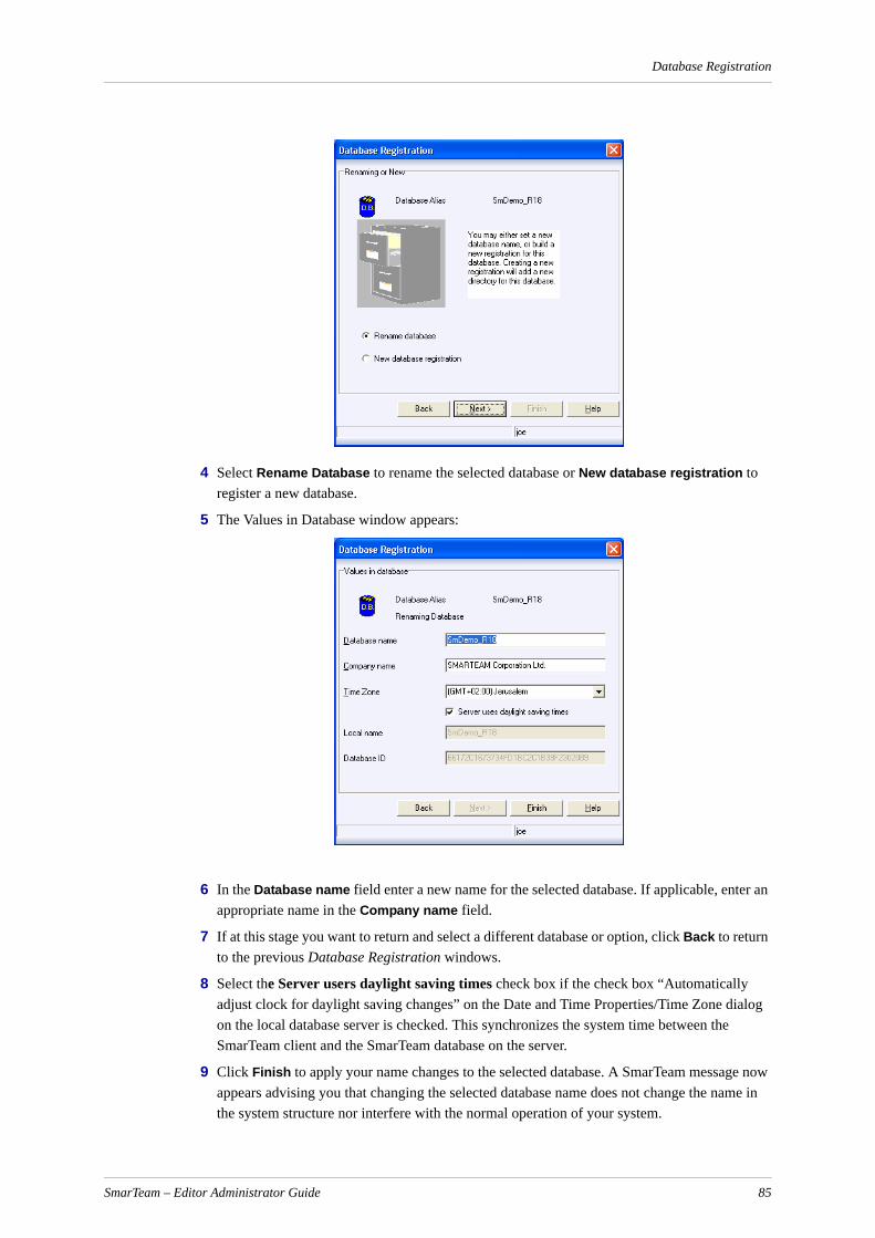
Database Registration
4 Select Rename Database to rename the selected database or New database registration to register a new database.
5 The Values in Database window appears:
6 In the Database name field enter a new name for the selected database. If applicable, enter an appropriate name in the Company name field.
7 If at this stage you want to return and select a different database or option, click Back to return to the previous Database Registration windows.
8 Select the Server users daylight saving times check box if the check box “Automatically adjust clock for daylight saving changes” on the Date and Time Properties/Time Zone dialog on the local database server is checked. This synchronizes the system time between the SmarTeam client and the SmarTeam database on the server.
9 Click Finish to apply your name changes to the selected database. A SmarTeam message now appears advising you that changing the selected database name does not change the name in the system structure nor interfere with the normal operation of your system.
SmarTeam – Editor Administrator Guide 85

Database Registration
10 In the SmarTeam message window click OK to proceed with your requested name change or click Cancel to abort your changes. When you select OK a second SmarTeam message window will appear, advising you that database registration was saved correctly. Click OK to return to the Database Registration window, which will now display the changed database name(s) as entered in step 6 above.
11 Click Close to exit the Database Registration utility.
SmarTeam – Editor Administrator Guide 86

Session Management Service
Session Management ServiceThe Session Management Service is a centralized service that supplies authentication and session validation across all SmarTeam applications.
The Session Management Service supports multiple authentication protocols to enable maximum utilization of existing identity systems in the organization such as Lightweight Directory Access Protocol (LDAP), Active Directory and Windows domains.
The Session Management Service centralizes authentication in the organization, thus enabling a "Single Sign-On" scenario in all SmarTeam applications. A user running a SmarTeam application will only authenticate once and will be able to run multiple SmarTeam applications without the need to re-authenticate.
The Session Management Service supports the following authentication protocols:
SmarTeam – This protocol uses a user name and password stored in a SmarTeam database to authenticate a user. This protocol is equivalent to the authentication protocol used in previous SmarTeam versions.
Windows - This protocol uses the currently logged-on user as the SmarTeam user by using Windows Authentication to revalidate that the credentials of this user are still valid.
Note: When using the Windows Authentication Protocol, the SmarTeam login window will not be displayed on launching SmarTeam Windows applications.
Lightweight Directory Access Protocol (LDAP) - This protocol uses a user name and password to authenticate a user against an LDAP server.
Active Directory - This protocol uses a user name and password to authenticate a user against Microsoft's Active Directory.
ImplementationSession Management Service is implemented in SmarTeam as follows
1 The user connects to a SmarTeam application for the first time in the current session.
2 The SmarTeam Login Window is displayed.
3 The user provides credentials (generally user name and password).
4 The user is authenticated by the system.
5 The user can now work in any SmarTeam application without being asked to supply credentials again.
6 When SmarTeam – Editor or SmarTeam – Web Editor are closed, they notify SmarTeam – Foundation to close the work session:
For SmarTeam – Editor, when a connection problem occurs between the client and the SmarTeam – Foundation server while SmarTeam – Editor is open, the session expiration instruction begins to track the time and the work session is terminated after the session expiration timeout is reached (by default, 20 minutes)
For SmarTeam – Web Editor, if it remains open but no activity is detected for 20 minutes, the IIS timeout closes the Internet Explorer connection and the work session is terminated after 20 minutes without activity
SmarTeam – Editor Administrator Guide 87

Session Management Service
7 The next time the user tries to connect to a SmarTeam application they are prompted to provide credentials again.
Note: Some utilities and modules always ask for credentials no matter what happened previously, some display a Login Window with default values (the user name and password fields filled in are the password is shown as *******), and others always attempt to use existing credentials (if present) and do not display any dialogs. These issues depend on how the utility was designed and its functionality.
Note: If an administrator or other user is logged into another machine for administrative purposes, they must close all SmarTeam applications (SmarTeam, Integrations and any other administrative tools) running before letting another user log in. This is in order to prevent them from accessing restricted information.
Password-Protected SessionPassword Protected Session enables the local SmarTeam administrator to prevent the running of unauthorized scripts that connect to the SmarTeam environment. This functionality will prevent unauthorized scripts from -
Accessing secured files in the vault (Retrieve/Delete/Add)
Executing any operation through SmarTeam API on:
SmarTeam database
Configuration settings
This functionality requires that all customer scripts include authorized passwords. These passwords are assigned by the administrator in the following cases:
The password is used for internal programming.
The password is derived from external applications and approved by the SmarTeam administrator.
The password used in the script should be encrypted and entered to the Configuration Settings and a hash password. To perform these operations, use the Security Configuration Tool.
For information on the API changes, refer to the STComRefGuide AuthorizeAccess section.
Security Configuration tool
The Security Configuration tool enables the administrator to encrypt the selected password used by developers and define it in the System Configuration.
SmarTeam – Editor Administrator Guide 88

Session Management Service
Code Password used by developersThe maximum password length is 12 characters
Get Hash Code Click to generate the Hash Code from the password that is filled in the password field
Hash Code This the password after encryption:• Filled by clicking Get Hash Code
or• Type the hash password of the external application
Select key A dropdown list from which to choose one of the following keys to update:• SecureSessionPassword1• SecureSessionPassword2• SecureSessionPassword3• SecureSessionPassword4• SecureSessionPassword5
SmarTeam – Editor Administrator Guide 89
Session Management Service
Changing the Session Management Services Expiration TimeThe default value for the timeout of the Session Management Services is 20 minutes.
To change this default:
1 Open the file SmarTeam.Std.SessionManagement.Service.Host.exe.config.
2 Change the <expiration>20</expiration> line as required. For example:
<sessionManagement><service><dataHandler>SmarTeam.Std.SessionManagement.Service.MemoryBasedSessionManagementDataHandler,SmarTeam.Std.SessionManagement, Version=5.17.1.67, Culture=neutral,PublicKeyToken=b4ecbcafd01b2516</dataHandler><expiration>10</expiration>
</service></sessionManagement>
Note: The expiration time must never be set to less than 5 minutes.
Authentication ManagerThe Authentication Manager is an administrative tool that enables administrators to configure the behavior of the Session Management Service. The Authentication Manager enables the administrator to select the authentication protocol used throughout the organization as well as the necessary parameters required to the authentication protocol selected.
The Authentication Manager can only run on the machine on which the Core Services are installed.
Note: When using the SmarTeam authentication protocol which uses a SmarTeam database to authenticate users by their user name and password, it will be impossible to login to any application if the database used for authentication is corrupted or missing.
To solve this problem, click "Reset database list" in the Authentication Manager. This button resets the database list and enables the administrator to reconfigure the corrupted or unavailable database.
Update key Click to enter the hash password for the key(s) defined in the Keys and Values list
Keys and values Shows all Hash Password keys and their values:• Number: Lists the order in which the selected keys will be
activated• Keys: Displays the keys available in the Select Key drop-
down list• Values: Displays the value for each of the keys available in
the Select Key list
Enable protected mode Mark this check box to activate the Password-protected Session functionality (this setting is saved in the EnableProtectedSessionMode key)
SmarTeam – Editor Administrator Guide 90

Session Management Service
Changing the Default Authentication ProtocolThe Authentication Manager controls the default authentication protocol used throughout the organization and all of its relevant parameters.
If you are working on a new installation of SmarTeam you MUST run the Authentication Manager after the installation of the Session Management Service in order to set the default authentication protocol.
To change the default protocol:
1 Go to the machine on which the Session Management Service is installed.
2 Run Start Menu, All Programs, SmarTeam, Administrative Tools, Authentication Manager.
The Authentication Manager window appears.
3 From the Authentication Protocol combo box, select the protocol you want to use.
4 You can authenticate a user name and password either against the SmarTeam – Web Editor database or against the SmarTeam – Editor database.
For authentication of the user against the SmarTeam – Web Editor database, select the left check box. You can select only one database from the list. Authentication will be done against this database only.
For authentication of the user against the SmarTeam – Editor database(s), select the right check box. Select the databases against which you want to peform authentication. Note that authentication is done against all the databases in the list and therefore the user name must appear in all these databases.
Note: If you select a database other than the default database, you must add the database name manually in the keys StorageTitle and ConnectionString in the Sytem Configuration Editor.
5 Fill in the appropriate fields according to the protocol selected. If you select the SmarTeam protocol, you will be asked to define your SmarTeam database to enable the SmarTeam authentication protocol to function properly.
6 When you have finished, click Apply.
SmarTeam – Editor Administrator Guide 91
Session Management Service
.NET Remoting Communication for Session Management
HTTP and HTTPS protocols are not the default protocols supported when using .NET remoting communication for Session Management.
To change the SmarTeam Session Management port:
Apply the change manually on the server and on each client to which the user is connected by amending the XML file.
Note: The Administrator must repeat this procedure for each Service Pack update.
Authentication Protocol Parameters
SmarTeam Authentication Protocol ParametersAuthenticate using only the following database: Allows you to set a single database against which all authentication requests will be performed, even when connecting to a different database.
Allow SmarTeam authentication only against the following SmarTeam databases: Allows you to specify a list of databases that are authorized to be used as the authentication source. This option eliminates the risk of a malicious user attaching a database locally and trying to authenticate to it, bypassing the currently-used authentication database
Lightweight Directory Access Protocol (LDAP) ParametersServer Name: The name of the LDAP server to be used for authentication.
Server Port: The TCP/IP port of the LDAP server (usually 389).
Search Base: The location in the LDAP directory from which to start looking for the users.
Search Attribute: The name of the attribute in the user class in which to search for the login name. For example, find a user by its Email address.
Admin Group Class Name: The name of the class of the Admin Group.
Admin Group Name: The name of the group in the LDAP server which all of its members will be considered by the Session Management Service as SmarTeam administrators.
Admin Group Attribute Name: The name of the attribute in the Admin Group class which holds the names of the group members.Active Directory Authentication Protocol Parameters.
Allow Anonymous Login: Select this check box if your organization’s LDAP is configured to allow anonymous login and searches to be performed.
Set Search Admin: If the Allow Anonymous Login check box is not checked, click Set Search Admin to open the LDAP Search User Form window. In this window, enter the name and password of the administrator who is authorized to login and search the organization’s LDAP.
Active Directory ParametersSearch Base: The location in the Active Directory from which to start looking for the users.
Search Attribute: The name of the attribute in the user class to be used to search for the login name. For example, find a user by its account name or Email address.
Admin Group Class Name: The name of the class of the Admin Group.
Admin Group Name: The name of the group in the Active Directory server which all of its members will be considered by the Session Management Service as SmarTeam administrators.
SmarTeam – Editor Administrator Guide 92

Session Management Service
Admin Group Attribute Name: The name of the attribute in the Admin Group class which holds the names of the group members.
Note: If you are not using dynamic Active Directory discovery, you may need to supply the server name running the Active Directory before the search base. For example: serverName/DC=MyDomain, OU=Users
Note: When User Authentication is set to Active Directory, it also applies to the Domain.
Windows Authentication Protocol
The Windows authentication protocol works in a similar way to the Active Directory authentication protocol. All the users should be imported to SmarTeam using the LDAP User Import tool, and must be from the domain that was configured in the Domain Controller.
Note: When using Windows authentication, SmarTeam – Foundation must be under the Domain Controller.
Note that there is no need to manually log into SmarTeam as login is performed automatically by recognizing the domain and the user login.
Admin Group in Windows, LDAP and Active Directory Authentication Protocols
Admin groups must be configured in the Windows, LDAP and Active Directory authentication protocol to enable the Session Management Service to determine if a certain user is a SmarTeam administrator.
Beginning from V5R13, some SmarTeam applications such as the System Configuration Editor require an authenticated SmarTeam administrator logged in to perform various tasks. As the System Configuration is not specific per database, the Session Management Service must have a way to verify if a certain user is logged in.
If the Admin groups are not defined, administrators will not be able to log into various applications.
When working with the active directory authentication protocol, the Admin Group Name must be set even if it is not known if this user will be the SmarTeam administrator. In order to function correctly, the Active Directory authentication protocol must know if there is an Admin Group.
Enabling SmarTeam Users to Use the SmarTeam Administrator Tools
To enable SmarTeam users to use the SmarTeam Administrator Tools, perform the following steps:
1 In the Active directory, create a SmarTeam Group (for example, StUsers) and assign users to this group.
2 In SmarTeam, launch the Authentication Manager.
3 From the Authentication Protocol field, select the Lightweight Directory Access Protocol (LDAP) or Active Directory.
The LDAP fields are shown. The right side of the screen contains the following fields:
Admin Group Class Name: = <group>
Admin Group Name = <empty>
SmarTeam – Editor Administrator Guide 93

Session Management Service
Admin Group Attribute Name = member
4 In the Admin Group Name field, type the name of the new group you created in the Active Directory, for example <StUsers>.
5 Save the authentication settings and exit.
6 In SmarTeam User Maintenance, add the SmarTeam Admin group you created in the Active Directory and attach users to this group.
Note: The group should be a SmarTeam administrator group. The users assigned to the group should also be defined as SmarTeam administrators so that they will be able to run the Admin tools.
Importing LDAP/Active Directory UsersUsers of LDAP /Active Directory protocols can be imported into SmarTeam and authenticated against the LDAP/Active Directory server. This is done using the LDAP/Active Directory Import Wizard.
Note: The user that logs in to the computer to activate the LDAP Import Wizard must be a domain administrator.
Mapping LDAP/Active Directory Users in SmarTeam
By default, LDAP/Active Directory user attributes are automatically mapped to their corresponding attributes in SmarTeam. However, if changes need to be made to the mapping, the system administrator can overwrite the default definitions in the System Configuration Service, Administrative Tools, LDAP User Import as shown below.
Click on a key name to update its value.
SmarTeam – Editor Administrator Guide 94
Session Management Service
Note: The mapping utility must be run before importing the LDAP/Active Directory users.
Running the Mapping Utility from the Command LineThe mapping utility can also be run from the command line as follows:
smarteam.std.ldapauthentication.userinput
When running the mapping utility from the command line, you can add any one (or more) of the parameters shown in the table.
Note: In order to run from the command line, the first parameter is mandatory (/no gui). For example smarteam.std.ldapauthentication.userinput
Mandatory fields are marked by *.
A sample command line is presented below:
smarteam.std.ldapauthentication.userinput /nogui /server myldapserver /searchbase OU=Users,O=SmarTeam,C=US /databasename PLMDB /databasepassword xx /userlogin joe /userpassword mypassword
Parameter Description
/nogui This parameter is required to run the mapping utility from the command line.
/server [server name] The LDAP server name/address.(*)
/searchbase [search base] The LDAP search base.(*)
/databasename [database name]
The SmarTeam database name
/databasepassword [database password*
The SmarTeam database password
/userlogin [user login]* The SmarTeam user login name
/userpassword [user password]*
The SmarTeam user password
/import [ALL/NEW/EXISTING]
The users to be imported (ALL = all the users, NEW = users that not exist in SmarTeam, EXISTING = just existing users in SmarTeam). The default is NEW
/ldapusername [ldap user name]
The LDAP user name
/ldapuserpassword [ldap user password]
The LDAP user password
/authenticationmode [NTLM/SIMPLE]
An authentication mode to authenticate against the LDAP server
/include [regexp] The users to be imported (a regular expression)
/ignore [regexp] The users not to import (a regular expression)
SmarTeam – Editor Administrator Guide 95

Session Management Service
Running the LDAP Users Import Wizard
To run the LDAP Import Wizard:
1 Click on the LDAP Import Wizard icon. The Welcome window appears.
2 Type in the LDAP server address and search base to the LDAP.
3 The Search Base is the Node in the LDAP server to search under it.
4 Mark the Windows Authentication Mode check box if your system uses the Windows Authentication protocol.
5 Select Next. The LDAP Import Details window appears.
SmarTeam – Editor Administrator Guide 96

Session Management Service
6 Select the users to be imported to SmarTeam or use the Select All or Deselect All.
7 Users marked in red already exist in SmarTeam. The administrator selects the user name and user details in SmarTeam.
8 Select Next.
9 The import process is completed and the selected users are imported into SmarTeam.
10 Select Copy to copy the report to the clipboard, or save to file to save the report to disk.
11 Select Finish.
Configuring a SmarTeam Client to Connect to a Different Session Management Service
To connect to a different Session Management Service:
1 Go to the Core Services server directory under <SmarTeam>\Bin.
2 Open the configuration file SmarTeam.Std.LocalConfiguration.dll.config.
3 Search for an element named FussConfigurationSectionHandler.
4 Under this element, find the line containing the text SessionManagement/Fuss.rem.
5 Change the server name that prefixes this line.
For example, to change from accessing the Session Management Service located on 127.0.0.1 (localhost), change:
tcp://127.0.0.1:5606/SessionManagement/Fuss.rem
to:tcp://<otherServerNameOrIPAddress>:5606/SessionManagement/Fuss.rem
SmarTeam – Editor Administrator Guide 97
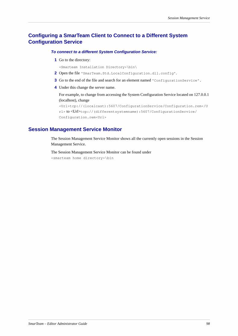
Session Management Service
Configuring a SmarTeam Client to Connect to a Different System Configuration Service
To connect to a different System Configuration Service:
1 Go to the directory:
<Smarteam Installation Directory>\bin\
2 Open the file "SmarTeam.Std.LocalConfiguration.dll.config".
3 Go to the end of the file and search for an element named "ConfigurationService".
4 Under this change the server name.
For example, to change from accessing the System Configuration Service located on 127.0.0.1 (localhost), change <Url>tcp://(localcast):5607/ConfigurationService/Configuration.rem</U
rl> to <Url>tcp://(differentsystemname):5607/ConfigurationService/ Configuration.rem<Url>
Session Management Service MonitorThe Session Management Service Monitor shows all the currently open sessions in the Session Management Service.
The Session Management Service Monitor can be found under <smarteam home directory>\bin
SmarTeam – Editor Administrator Guide 98
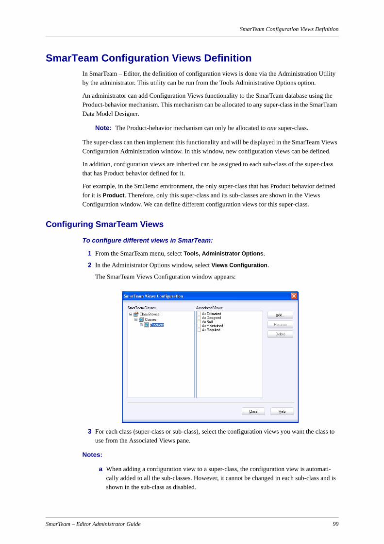
SmarTeam Configuration Views Definition
SmarTeam Configuration Views DefinitionIn SmarTeam – Editor, the definition of configuration views is done via the Administration Utility by the administrator. This utility can be run from the Tools Administrative Options option.
An administrator can add Configuration Views functionality to the SmarTeam database using the Product-behavior mechanism. This mechanism can be allocated to any super-class in the SmarTeam Data Model Designer.
Note: The Product-behavior mechanism can only be allocated to one super-class.
The super-class can then implement this functionality and will be displayed in the SmarTeam Views Configuration Administration window. In this window, new configuration views can be defined.
In addition, configuration views are inherited can be assigned to each sub-class of the super-class that has Product behavior defined for it.
For example, in the SmDemo environment, the only super-class that has Product behavior defined for it is Product. Therefore, only this super-class and its sub-classes are shown in the Views Configuration window. We can define different configuration views for this super-class.
Configuring SmarTeam Views
To configure different views in SmarTeam:
1 From the SmarTeam menu, select Tools, Administrator Options.
2 In the Administrator Options window, select Views Configuration.
The SmarTeam Views Configuration window appears:
3 For each class (super-class or sub-class), select the configuration views you want the class to use from the Associated Views pane.
Notes:
a When adding a configuration view to a super-class, the configuration view is automati-cally added to all the sub-classes. However, it cannot be changed in each sub-class and is shown in the sub-class as disabled.
SmarTeam – Editor Administrator Guide 99

SmarTeam Configuration Views Definition
b When a configuration view is added to a sub-class, it is available to the super-class and all other views, but is not checked by default. You can then choose this view for other sub-classes. If you check this view on the super-class, it behaves as described in note a above.
To add a new configuration view:
1 Select the super-class or sub-class to which you want to add the view.
2 Select Add.
The Update Class View window appears.
3 Type in a name for the new configuration view and click OK.
The new view is added to the selected super-class/sub-class and all sub-classes belonging to this super-class.
To rename a configuration view:
1 Select the configuration view from the list of associated views.
2 Select Rename.
The Update Class View window appears.
3 Type in a name for the new configuration view and click OK.
To delete a configuration view
1 Select the configuration view from the list of associated views.
2 Select Delete.
A confirmation message is displayed.
3 Select Yes to delete to confirm the delete operation.
SmarTeam – Editor Administrator Guide 100

Lifecycle Behavior
Lifecycle BehaviorSmarTeam enables you to tailor the Lifecycle behavior to fit your organization's needs. For example, you can specify a company rule to always use the latest revision upon creating a new revision. Implementing the above rule reverts all children of an assembly to the latest available version, regardless to the current version displayed in the tree. In addition, the Lifecycle Options provides access to the Lifecycle preferences.
Lifecycle Options – Global Lifecycle settings: Enables the administrator to define general settings for the Lifecycle. The Options screen is divided into 'into the vault operations' and 'out of the vault operations'.
User scenarios of working with the Lifecycle Rules Setup include:
View or change Lifecycle (global) options - Allows you to manage Lifecycle options.
View Lifecycle Rules - Allows you to explore SmarTeam Lifecycle rules and see the results of a specific Lifecycle operation on dependent objects and recognize conflicts.
Update Lifecycle Rules - Changes the rule configuration to customize the Lifecycle behavior.
Evaluate Lifecycle Rules - Provides a way to evaluate Lifecycle rules under specific conditions.
Defining Lifecycle OptionsYou can easily custom-design different Lifecycle options via the Lifecycle Options window. For instance, you can define whether a user can define a revision number or whether users can create revision branches.
To define Lifecycle options:
1 From the SmarTeam – Editor main menu select Tools then sub-menu Administrator Options… to display the Administrator Options window.
2 In the Lifecycle section, click Lifecycle Options… to display the Lifecycle Options window.
SmarTeam – Editor Administrator Guide 101

Lifecycle Behavior
The Lifecycle Options window is divided into four separate pages:
The General page allows you to select general options that affect all Lifecycle operations.
The Into Vault page allows you to set options relevant for Check In, Release and Obsolete operations.
The Out of Vault page allows you to set options for Check Out and New Release operations.
The Locked Tree page allows you to set options for copying links and changing locked structures and enabling revisions of items.
An explanation of the options available on each page is provided below.
3 After making any changes, click OK to save your changes – or click Cancel to abort any changes made – and to close the Lifecycle Options window.
4 In the Administrator Options window, click Close to exit.
SmarTeam – Editor Administrator Guide 102

Lifecycle Behavior
Defining Document Lifecycle Options
General
The General tab presents general administrator lifecycle options:
It contains the following options:
Disable lifecycle window properties assigned by a script
When checked, SmarTeam – Editor forces you to create a new name or new revision numberfor an object when the destination vault already has an object with that name. You will not beable to check in the object without changing its name or revision number.When unchecked, SmarTeam – Editor allows you to check in and overwrite an object if anobject exists in the vault with the exact same name. A message is displayed asking you if you want to overwrite. If you click Yes, the new objectoverwrites the previous object of the same name, thereby erasing the previous object from thevault. If you click No, you can then change the name of the new object. For example: You have an object named Drawing-55.2 that you want to check in to the vault,and an object already exists with the same name in the vault. If the option was checked,SmarTeam – Editor would not allow you to check the object into the vault and would force youto change its name or revision number. If the option was left unchecked, then a message isdisplayed asking if you wish to overwrite the existing Drawing -55.2. You then have the optionto overwrite or rename. Disable Lifecycle window properties assigned by a script.When checked, enables you to control the ability to change attributes on Lifecycle forms ifattributes were set by scripting.
SmarTeam – Editor Administrator Guide 103

Lifecycle Behavior
Enable Vault Server servicesWhen checked, this option enables you to use the Vault Server when assigning vaults fordifferent types of objects. Instead of defining local vault directories in the Vault MaintenanceWindow, vault names that have been defined in the Vault Server can be assigned as destinationvaults for Projects and file types. Refer to Vault Server Details Window for further details.
If there is no link to project, choose vault based on current projectWhen checked, this option enables you to use a specific part of the SmarTeam vaultassignment algorithm to determine where a file will be located when it is copied to a vault.
Enable user-defined revisionsWhen checked, SmarTeam – Editor enables you to create your own revision number in the Check In window when you check an object into the vault. In the Check In window, the User Defined option button will be enabled, allowing you to enter a revision number in the Revision field.When unchecked, the User Defined option button is disabled and you will not be able to create your own revision number.
Lifecycle Dialog Type Select the type of Lifecycle Options screen to appear when performing lifecycle operations. This combo box contains three options:
No Dialog: No Lifecycle Options screen appears. All lifecycle operations are performed on the selected objects using the default settings.
Light Lifecycle Screen: The Lifecycle screen displays the minimum number of options that are available to the user. See Defining Lifecycle Options for details.
Advanced Lifecycle Screen: The Lifecycle screen displays all the options available to the administrator.
These changes only take affect after the user exits then re-enters SmarTeam – Editor.
Last public revision mode
Note: Changing the Last Public Revision Mode does not change the Last Public Revision of existing documents but affect new lifecycle operations only.
Since a document can have numerous revision numbers, SmarTeam – Editor enables you to define which revision is considered the last revision. For example, you can define that only objects that are Released (using the Release option) are assigned the last revision status.
The last revision status affects the following SmarTeam – Editor operations:
Tree Properties
Searches
Branching
Three options are available from the dropdown list in order to determine the last revision status of all objects in SmarTeam – Editor:
Release Only
Check In
Check In and Release
Release Only: The last revision status is assigned to the last Released revision of an object. In cases where a Released revision does not yet exist, the last revision status is assigned to the last Checked In revision of that object. If an object was Released (as b.0 for example) and then
SmarTeam – Editor Administrator Guide 104
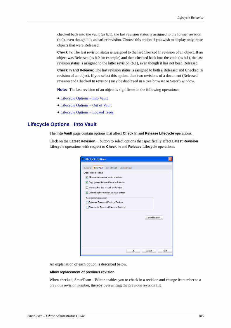
Lifecycle Behavior
checked back into the vault (as b.1), the last revision status is assigned to the former revision (b.0), even though it is an earlier revision. Choose this option if you wish to display only those objects that were Released.
Check In: The last revision status is assigned to the last Checked In revision of an object. If an object was Released (as b.0 for example) and then checked back into the vault (as b.1), the last revision status is assigned to the latter revision (b.1), even though it has not been Released.
Check In and Release: The last revision status is assigned to both a Released and Checked In revision of an object. If you select this option, then two revisions of a document (Released revision and Checked In revision) may be displayed in a tree browser or Search window.
Note: The last revision of an object is significant in the following operations:
Lifecycle Options – Into Vault
Lifecycle Options – Out of Vault
Lifecycle Options – Locked Trees
Lifecycle Options – Into VaultThe Into Vault page contain options that affect Check In and Release Lifecycle operations.
Click on the Latest Revision… button to select options that specifically affect Latest Revision Lifecycle operations with respect to Check In and Release Lifecycle operations.
An explanation of each option is described below.
Allow replacement of previous revision
When checked, SmarTeam – Editor enables you to check in a revision and change its number to a previous revision number, thereby overwriting the previous revision file.
SmarTeam – Editor Administrator Guide 105
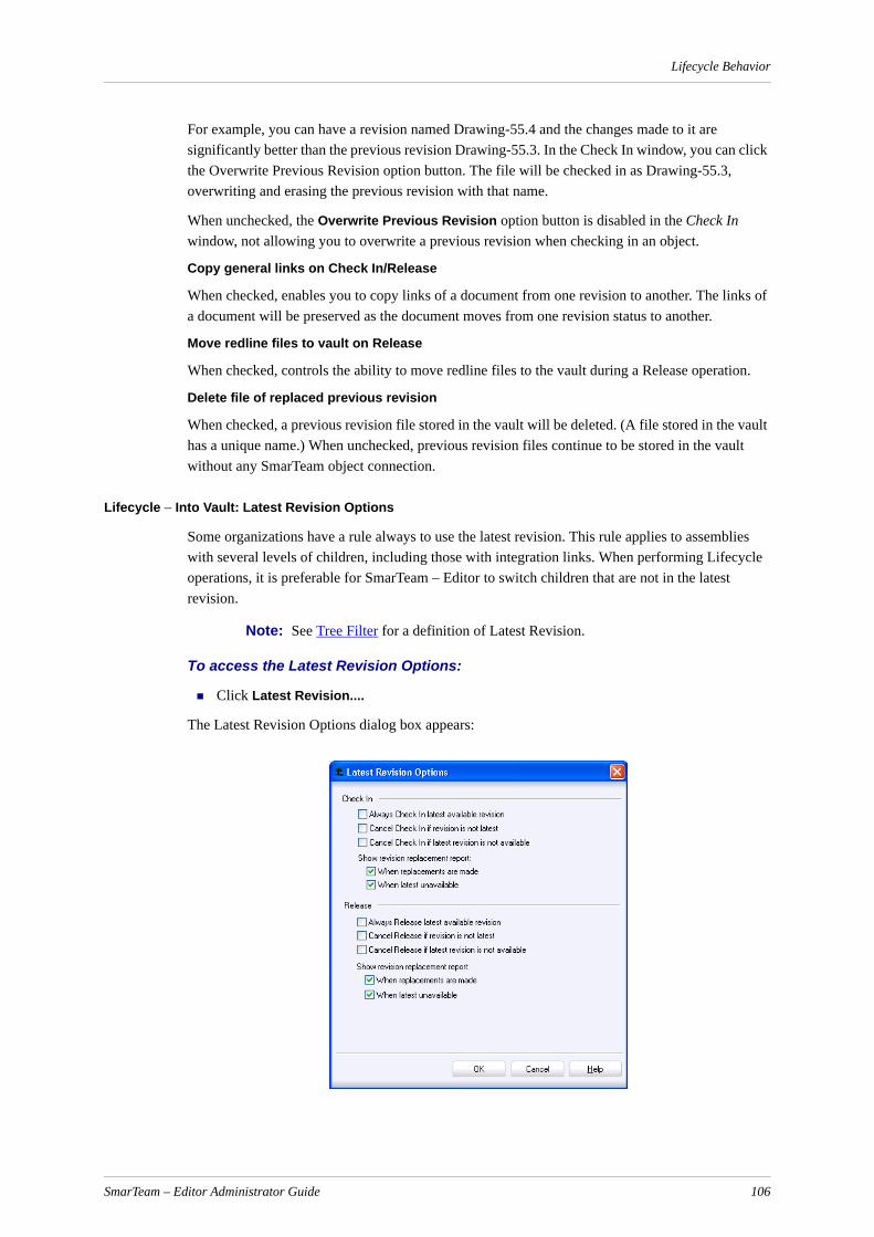
Lifecycle Behavior
For example, you can have a revision named Drawing-55.4 and the changes made to it are significantly better than the previous revision Drawing-55.3. In the Check In window, you can click the Overwrite Previous Revision option button. The file will be checked in as Drawing-55.3, overwriting and erasing the previous revision with that name.
When unchecked, the Overwrite Previous Revision option button is disabled in the Check In window, not allowing you to overwrite a previous revision when checking in an object.
Copy general links on Check In/Release
When checked, enables you to copy links of a document from one revision to another. The links of a document will be preserved as the document moves from one revision status to another.
Move redline files to vault on Release
When checked, controls the ability to move redline files to the vault during a Release operation.
Delete file of replaced previous revision
When checked, a previous revision file stored in the vault will be deleted. (A file stored in the vault has a unique name.) When unchecked, previous revision files continue to be stored in the vault without any SmarTeam object connection.
Lifecycle – Into Vault: Latest Revision Options
Some organizations have a rule always to use the latest revision. This rule applies to assemblies with several levels of children, including those with integration links. When performing Lifecycle operations, it is preferable for SmarTeam – Editor to switch children that are not in the latest revision.
Note: See Tree Filter for a definition of Latest Revision.
To access the Latest Revision Options:
Click Latest Revision....
The Latest Revision Options dialog box appears:
SmarTeam – Editor Administrator Guide 106
Lifecycle Behavior
An explanation of each option is presented below.
Check In
Always check in latest available revision
When checked, SmarTeam – Editor reverts to the latest available revision; this also applies to invisible associative objects.
Note: SmarTeam – Editor will not replace with the latest revision when the current revision of the object in the tree is the latest revision.
Cancel Check In if revision is not the latest
When checked, SmarTeam – Editor will cancel the Check In operation if the object being checked in to the vault is not the latest revision.
Cancel Check In if the latest revision is not available
When checked, SmarTeam – Editor will cancel a Check In operation if the latest revision is not available (i.e. checked out).
Show Revision Replacement Report
Revision Replacement Reports appear on the screen whenever one or both of the following options is/are checked. (The report shows a tree with four states for each item that describes the latest revision status.)
When replacements are made
When checked, a report is generated on the screen.
When latest is not available
When checked, a report is generated on the screen.
Release
Always release latest available revision
When checked, SmarTeam – Editor reverts to the latest available revision; this also applies to invisible associative objects.
Note: SmarTeam – Editor will not replace with the latest revision when the current revision of the object in the tree is the latest revision.
Cancel release if revision is not latest
When checked, SmarTeam – Editor will cancel the Release operation if the object being released to the vault is not the latest revision.
Cancel Release if latest revision is not available
When checked, SmarTeam – Editor will cancel the Release operation if the latest revision is not available (i.e. released).
Show Revision Replacement Report
Revision Replacement Reports appear on the screen whenever one or both of the following options is/are checked. (The report shows a tree with four states for each item that describes the latest revision status.)
When replacements are made
When checked, a report is generated on the screen.
SmarTeam – Editor Administrator Guide 107

Lifecycle Behavior
When latest unavailable
When checked, a report is generated on the screen.
The following options are added to this page in order to force root-object linking to parents of the previous revision:
Automatically replace in:
Released Parents of Previous Revision
Link the object to the released parents of the previous revision.
Checked-in Parents of Previous Revision
Link the object to the checked in parents of the previous revision.
Notes:
a You can only link the new revision to a parent object that is in Checked In or Released state.
b The object is replaced only in case a check in/release operation is performed on the object. If you select the parent object and as result a check in/release operation is performed on the object, this object will not be replaced in the parent of a previous revision.
Lifecycle Options – Out of VaultThe Out of Vault page contains options that affect Check Out, New Release and Copy Lifecycle operations.
An explanation of each option is presented below.
Restrict new release operation when derived revision exists
SmarTeam – Editor Administrator Guide 108

Lifecycle Behavior
When checked, controls the ability to restrict new releases on objects that have derived revisions. This option should only be checked after creating a new branch from a released object and you want to prevent a New Release operation being performed on the previous branch.
Warn on New Release/Check Out/Copy to remote drive
When checked, a warning message is generated when a user is copying or checking out to a remote drive when numerous users are also sharing the same directories. The message requests the user to confirm the operation to check out or copy to the selected drive.
Warn on Life Cycle for Documents linked to Active items
When checked, a warning message is generated when an object is connected by a specification link to an active item.
Allow branching
To enable two departments to develop a product at the same time, different revision branches must be created so that at a later stage of development a revision branch can be merged or deleted.
When checked, SmarTeam – Editor enables you to create parallel branches of a revision based on the same file. Each branch will be assigned a different revision number consisting of three characters (a.0.1 and a.0.2 for example) instead of the standard revision number consisting of two characters (e.g., a.0).
For example: You can have a Drawing named Pump-55. If the Branching value is enabled, two separate users can check out the file and each can create a new revision of this file. Two different revision numbers will be assigned to these files respectively (a.0.1 and a.0.2) and they can both be modified simultaneously.
To create branches, when you check out a file, click the New Branch check box in the Check Out window to create a new branch revision for the file:
The New Revision field automatically changes to display a revision number with three digits.
When unchecked, the New Branch checkbox in the Check Out window is disabled.
Copy general links on Check Out/New Release
When checked, enables you to copy links of a document from one revision to another. The links of a document will be preserved as the document moves from one revision status to another.
Last revision policy for overwrite local files upon Check Out/Copy
This preference determines how SmarTeam – Editor handles revision conflicts for files located in the working area.
When checked, a Read only local file will be overwritten only if the copied file is a newer revision, thus preventing a loss of data in changed files. A user will be unable to change the setting in the Lifecycle window (Replace File tab) nor select default behavior for overwriting files that already exist in the working directory.
Compare revisions before automatic replacement of files upon Check Out/Copy
When checked and the Automatic Overwrite option exists, overwriting is only done on a local object if it is less recent than the copied object. If the local object is newer or more recent than the copied object, a message is displayed for user decision.
When unchecked, a time comparison is not made.
SmarTeam – Editor Administrator Guide 109
Lifecycle Behavior
Notes: For specific configurations, the following scenario takes place:
When checked and the automatic overwrite option exists, overwriting is only carried out on local objects if they are less recent than the copied objects. If any local object in the Life Cycle Dialog is newer or more recent than the copied object, a message is displayed and the User must choose to Continue or Cancel the Lifecycle Operation.
If Continue is selected, Lifecycle Operations will only occur on the Copied objects that are newer or more recent than the local objects or if a local object does not already exist in the Working Directory for the objects.When unchecked, a time comparison between the objects in the Lifecycle window and the objects in the Working Directory is not made and SmarTeam will allow you to overwrite newer objects in the Working Directory when the automatic overwrite option exists.
Allow Switch Children to Latest for Copy
If Always check out latest available is set to True, by default, this check box is also checked.
For a Copy operation:
When Open for Edit is selected, even if it set to False, Allow Switch Children to Latest for Copy can be selected.
When Open for read-only is selected, Allow Switch Children to Latest for Copy is disabled.
If Open for Edit is selected, and Allow Switch Children to Latest for Copy is selected, the Not latest children are also replaced.
If Allow Switch Children to Latest for Copy and Switch children to Latest is selected, all child items are replaced.
IF Switch children to Latest is selected, switch to latest is performed for children of checked out parents.
If Allow Switch Children to Latest for Copy is selected or neither are selected, nothing changes to latest.
Set Light Weight Mode as Default
When checked, the Light Lifecycle screens are displayed by default.When working in the SmarTeam - CATIA Integration, the Set Light Weight Mode as Default is used for CATIA parts when they must be copied to the work directory. When using Light Weight mode, only .cgr files are copied to the work directory.
Note: When the Set Light Weight Mode as Default checkbox is marked, the Copy an Original File Only check box is disabled by default.
Copy an Original File Only
When checked, only original files are copied and the Set Light Weight Mode as Default check box is disabled by default.
Replace local files on Copy
This option enables you to determine whether a file that is copied to a user's work directory will overwrite a duplicate copy of the same file. For example, a user can be modifying an assembly called Assem1.sldasm. The user can then copy an assembly to the work directory that contains the same part as one of its sub-assembly.
SmarTeam – Editor Administrator Guide 110

Lifecycle Behavior
This option determines if the second copy of this part will overwrite the existing copy of the part. Click on the dropdown arrow to select one of options: Yes, No, Ask and Yes, when not in Work.
SmarTeam – Editor will overwrite a read-only file. If the file in the user's work directory is a read-only file, then the new copy of the file will overwrite the existing copy. For example, a user could have copied a part to the work directory that contains Assem1.sldasm as a sub-assembly. This sub-assembly file is a read-only file, as it was copied to the work directory as part of an assembly only. If the user then decides to check out and modify this specific sub-assembly (sldasm), the new file will overwrite the existing one in the work directory.
Select one of the following options
Replace local files on Check Out/New Release
This option is similar to the previous option and the same options are available from the dropdown list. During a Check Out/New Release operation, SmarTeam – Editor can detect a duplicate file on the work directory. You can then determine whether to overwrite a file or create a copy when the user is checking out the file. Choose one of the options described below.
Yes Local files in the user's work directory will always be overwritten. The Evaluation Report will or will not appear depending on the value of the key.LifecycleDisplayWarningBeforeOverwriting.
If it is set to True, an Evaluation Report is displayed stating that the files will be overwritten.
If it is set to False, the local files are replaced without an Evaluation Report appearing.
No SmarTeam – Editor will not copy the file to the work directory if a duplicate copy already exists on the user's work directory.
Ask When a user copies a file to the work directory and a duplicate of this file already exists at the work directory, a message or Evaluation Report is displayed, depending upon the settings defined for the LIFE_CYCLE.LifeCycleEvaluationReport key in the System Configuration.The warning message File <file name> of <object name> already exists in <path of folder>. The file cannot be replaced by object <name> file is displayed. The user is prompted to click Continue to continue the operation without overwriting the local file, or Cancel to cancel the operation.
Yes, when not in work
Allows you to overwrite when the file is not checked out. By default, this option is selected.
SmarTeam – Editor Administrator Guide 111
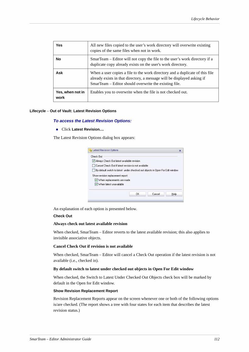
Lifecycle Behavior
Lifecycle – Out of Vault: Latest Revision Options
To access the Latest Revision Options:
Click Latest Revision....
The Latest Revision Options dialog box appears:
An explanation of each option is presented below.
Check Out
Always check out latest available revision
When checked, SmarTeam – Editor reverts to the latest available revision; this also applies to invisible associative objects.
Cancel Check Out if revision is not available
When checked, SmarTeam – Editor will cancel a Check Out operation if the latest revision is not available (i.e., checked in).
By default switch to latest under checked out objects in Open For Edit window
When checked, the Switch to Latest Under Checked Out Objects check box will be marked by default in the Open for Edit window.
Show Revision Replacement Report
Revision Replacement Reports appear on the screen whenever one or both of the following options is/are checked. (The report shows a tree with four states for each item that describes the latest revision status.)
Yes All new files copied to the user’s work directory will overwrite existing copies of the same files when not in work.
No SmarTeam – Editor will not copy the file to the user’s work directory if a duplicate copy already exists on the user's work directory.
Ask When a user copies a file to the work directory and a duplicate of this file already exists in that directory, a message will be displayed asking if SmarTeam – Editor should overwrite the existing file.
Yes, when not in work
Enables you to overwrite when the file is not checked out.
SmarTeam – Editor Administrator Guide 112

Lifecycle Behavior
When replacements are made
When checked, a report is generated on the screen.
When latest is not available
When checked, a report is generated on the screen.
Managing Satellite Objects
Satellite objects, used in 3DLive, are used for saving instance information (such as positioning information) in SmarTeam. To enable satellites, set the IsSupportSatellitesInLC key to True in SmarTeam System Configuration Editor. The IsSupportSatellitesInLC key specifies whether it is possible to copy satellite objects when performing a Check Out/New Release operation.
Lifecycle Options – Locked Trees
IMPORTANT! The Locked Trees page relates to all item lifecycle states which have a locked property defined for them. In SmDemo, there are two such states: Released and Active.
This page allows you to set options for copying links and changing locked items structure.
An explanation of each option is presented below.
Copy Specification Links on New Item RevisionWhen performing a new item revision operation, copy the specification link between a document and the new item. Copy General Links on New Item RevisionWhen performing a new item revision operation, copy the general link between a document and the new item. Allow Change of Locked Structures
SmarTeam – Editor Administrator Guide 113

Lifecycle Operations Recovery
Allow the structure of a locked item with children to be changed. Enable user-defined Revisions for ItemsAllow the Revision attribute to be edited during a New Revision operation on an item.
Lifecycle Operations RecoveryLifecycle operations are performed from from the child object up to the parent object. A lifecycle operation is performed on each object in the following sequence:
1. Update the object in the SmarTeam database.
2. Copy the file.
3. Update the file catalog.
For performance reasons, the file catalog is updated once only for all the objects that participate in a lifecycle operation.
If there is a computer failure during the course of a lifecycle operation, the lifecycle operation cannot be completed. If this happens, the information in the File Catalog will not match the information in the SmarTeam database.
The Lifecycle Operations Recovery procedure allows the user to update the File Catalog according to the information in database using the SmarTeam Log File.
Accessing the Lifecycle Operations Recovery ScreenThere are two ways of accessing the Lifecycle Operations Recovery screen:
Automatically: After a system failure, when you enter SmarTeam again, if more than the timeout period has passed, the Lifecycle Operations Recovery screen is displayed automatically.
Note that the timeout period is defined in the System Configuration Editor key LIFE_CYCLE.LifeCycleOperationTimeOutInMinutes on the Domain level. The default value is 5 minutes.
Manually: By selecting the Tools, List of Failed Operations option.
Lifecycle Operations Recovery ScreenThe Lifecyle Operations Recovery screen shows a list of failed operations from the last SmarTeam session. For each failed operation, the date, operation name, description and computer id are presented.
A sample Lifecyle Operations Recovery screen is shown below.
SmarTeam – Editor Administrator Guide 114

useViewSecurity Parameter
From this screen, you can perform the following operations:
Recover: Recover the selected lifecycle operation that has failed. This manually synchronizes the File Catalog with the database.
Delete: Delete the lifecycle operation from the database without completing it. This is not recommended as this results in a conflict between the information in the SmarTeam database and in the File Catalog.
Close: Close the window without making changes.
useViewSecurity ParameterWhen the preference for the useViewSecurity parameter is defined as TRUE, SmarTeam support for View Object Security while working with operations is enabled and the user cannot receive secured information about the object. A common warning message is generated in the Lifecycle report.
The default value for this preference is FALSE and results in backward compatibility.
The useViewSecurity preference is located in the smarteam.std.lifeCycle.config.xml file and can be accessed using the Find option of the System Configuration Editor..
SmarTeam – Editor Administrator Guide 115
Lifecycle Rules Setup
Lifecycle Rules SetupThe Lifecycle Rules Setup tool enables the creation of engineering business logic for Enterprise engineering processes. It reflects all the possible steps of a Product Lifecycle.
The Lifecycle Rules Setup defines rules for Lifecycle operations on linked objects throughout a lifecycle (as a result of an operation performed on a specific object).
The Lifecycle Rules Setup is an administrative application tool that enables users to define and manage business rules, object states and maturity phases for lifecycle operations.
By using the Lifecyle Rules Setup, an administrator can create effective release management processes for the Enterprise.
Using this tool, you can:
Review and create default rules
Modify rules provided by specific Integration applications
Add, remove or modify custom rules
Define Item mangement rules for product maturity phases
Lifecycle RulesAll rules set in your SmarTeam system can be divided into two groups:
Item RulesThese rules apply to the lifecycle of an item. You can define the rules for three lifecycle opera-tions: Demote, Inactivate and Promote. The Item Rules are checked in lifecycle operations and are not checked while performing Link operations. For details on Item Management, see Item Management. Document RulesThese rules apply to the lifecycle of documents. Document Rules are further divided into two groups by link types:
General rules: Rules that apply to objects linked by hierarchical links. General Link Rules define how to treat the child object, when performing a Lifecycle operation on a parent object. These rules apply to hierarchical links. All objects of this type will be assigned these rules.
Integration rules: Rules that apply to objects linked by different integration links. These rules are provided by the specific CAD Integration/Application. These rules apply to inte-gration-specific links (e.g., SolidWorks and CATIA links). Each rule defines the destination operation to be applied to the destination object, when performing a Lifecycle operation on a source object, when a specific link type links these two objects.
Integration Link Rules are applied to integration component types. Each integration has different rules for the component types.For component type rules, the rule is built according to the component type applied by the integration to the object. For example, when you perform a checkout operation on a CAD drawing, the dependent item on which the drawing is based, needs to be checked out or copied. Only after this is done, can the CAD application open the drawing. In other words, the CAD drawing depends on that item.
SmarTeam – Editor Administrator Guide 116

Lifecycle Rules Setup
In the above example, one rule for a drawing that is linked to an item may be defined as follows:When the drawing is changed (i.e., a check out operation is performed on it), the dependent item must also be changed (checked out). Or, a rule may specify that when you view the drawing (copy), the item must also be copied. In this case, the dependent object that is an item, must also be checked out.Integration Link Rules cannot be deleted.
Both rule groups can include custom rules defined by the user known as user-defined class rules.
Terminology Below is a list of basic terminology to orient you in using the Lifecycle Rules Setup.
Viewing Lifecycle Rules
To access the Lifecycle Rules Setup utility and view lifecycle rules:
1 From the Tools menu, select Configuration Options, Lifecycle Rules Setup.
The SmarTeam User Login window appears.
2 In the SmarTeam User Login window, enter your user name and password, if necessary.
3 Click OK.
Note: Only the Administrator has access to the Lifecycle Rules Setup.
The Lifecycle Rules Setup screen appears.
Item State A mode that signifies the state of an item in its entire lifecycle and assigns specific behavior to the item or its item structure.
Item State Property A characteristic of an item state that enables a specific action to be performed on an item.
Lifecycle Operation An action that enables the movement of an object from one state to another.
Lifecycle Rules Conditions that are performed on each object state in order to ensure the validity of an object within its lifecycle.
Source (Original) Object The original object on which the lifecycle operation is performed.
Original State The state from which the lifecycle operation is performed on the source object.
Destination Object The object that is linked to the original object.
Destination State The state to which the lifecycle operation is performed.
Link Type The type of link that links the source and destination objects. This is defined by the specific SmarTeam integration. For example, SolidWorks Drawing of link, In Context link, Derived Item link.
SmarTeam – Editor Administrator Guide 117
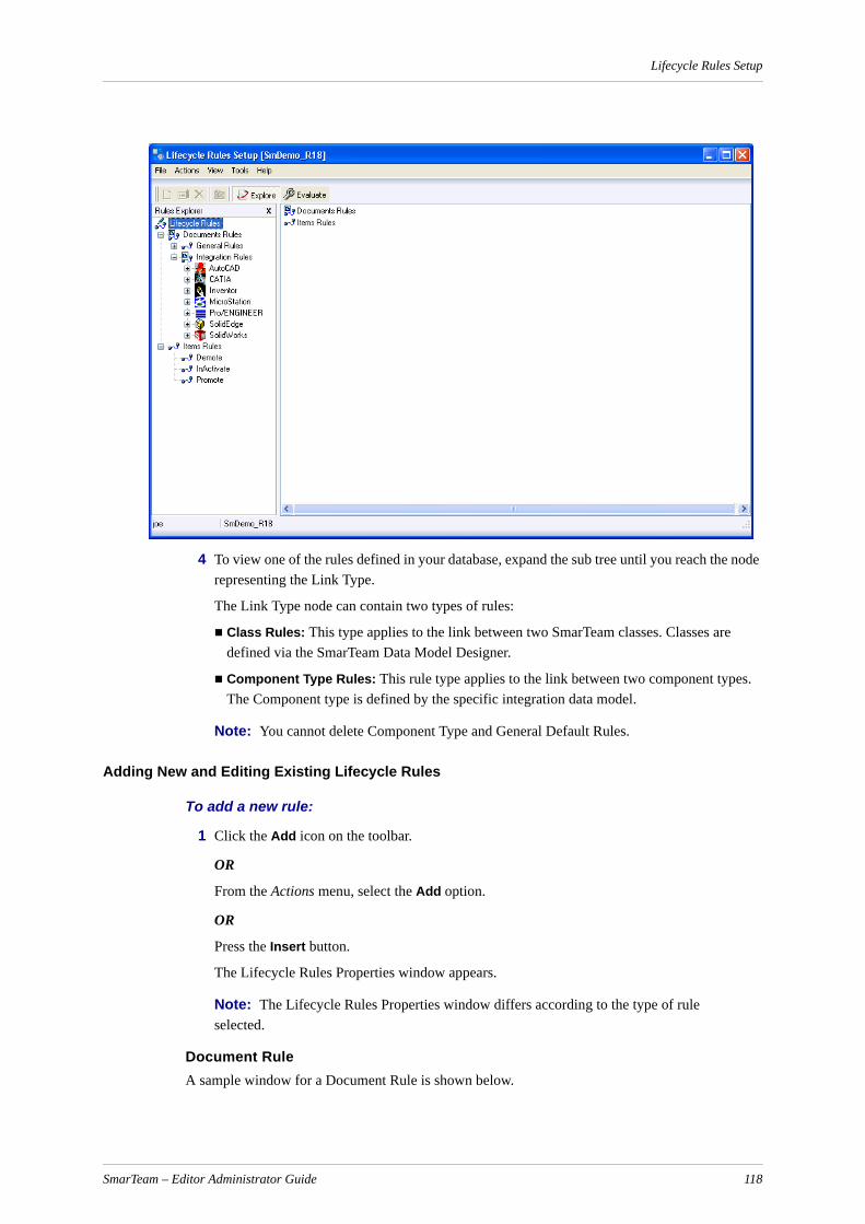
Lifecycle Rules Setup
4 To view one of the rules defined in your database, expand the sub tree until you reach the node representing the Link Type.
The Link Type node can contain two types of rules:
Class Rules: This type applies to the link between two SmarTeam classes. Classes are defined via the SmarTeam Data Model Designer.
Component Type Rules: This rule type applies to the link between two component types. The Component type is defined by the specific integration data model.
Note: You cannot delete Component Type and General Default Rules.
Adding New and Editing Existing Lifecycle Rules
To add a new rule:
1 Click the Add icon on the toolbar.
OR
From the Actions menu, select the Add option.
OR
Press the Insert button.
The Lifecycle Rules Properties window appears.
Note: The Lifecycle Rules Properties window differs according to the type of rule selected.
Document RuleA sample window for a Document Rule is shown below.
SmarTeam – Editor Administrator Guide 118

Lifecycle Rules Setup
2 For the Document Rule Properties, fill in the fields as described below
Field Description
Link Class Defines the link between two SmarTeam classes.
Direction Defines the direction of the link object, which can be Normal or Reverse.
Original Classor: Original Component Typeor:
SmarTeam Class Destination Component Type
or:
SmarTeam class Original Operation
Defines the class or component type of the object on which you perform the Lifecycle operation.Defines the class or component type of the dependent object
Defines the operation on the source object. All SmarTeam Lifecycle operations are available.
Destination operation Defines the operation on the dependent object as a result of the operation on the original object. The availability of the destination operation depends on the selected original operation. For example, if the original operation is Check Out then the available destination operations are Check Out, Copy File or No Operation.
SmarTeam – Editor Administrator Guide 119
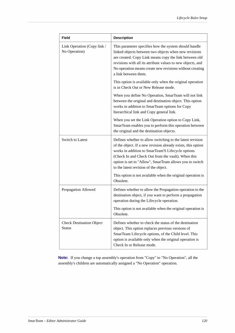
Lifecycle Rules Setup
Note: If you change a top assembly's operation from "Copy" to "No Operation", all the assembly's children are automatically assigned a "No Operation" operation.
Link Operation (Copy link / No Operation)
This parameter specifies how the system should handle linked objects between two objects when new revisions are created. Copy Link means copy the link between old revisions with all its attribute values to new objects, and No operation means create new revisions without creating a link between them.
This option is available only when the original operation is in Check Out or New Release mode.
When you define No Operation, SmarTeam will not link between the original and destination object. This option works in addition to SmarTeam options for Copy hierarchical link and Copy general link.
When you set the Link Operation option to Copy Link, SmarTeam enables you to perform this operation between the original and the destination objects.
Switch to Latest Defines whether to allow switching to the latest revision of the object. If a new revision already exists, this option works in addition to SmarTeam'S Lifecycle options (Check In and Check Out from the vault). When this option is set to "Allow", SmarTeam allows you to switch to the latest revision of the object.
This option is not available when the original operation is Obsolete.
Propagation Allowed Defines whether to allow the Propagation operation to the destination object, if you want to perform a propagation operation during the Lifecycle operation.
This option is not available when the original operation is Obsolete.
Check Destination Object Status
Defines whether to check the status of the destination object. This option replaces previous versions of SmarTeam Lifecycle options, of the Child level. This option is available only when the original operation is Check In or Release mode.
Field Description
SmarTeam – Editor Administrator Guide 120
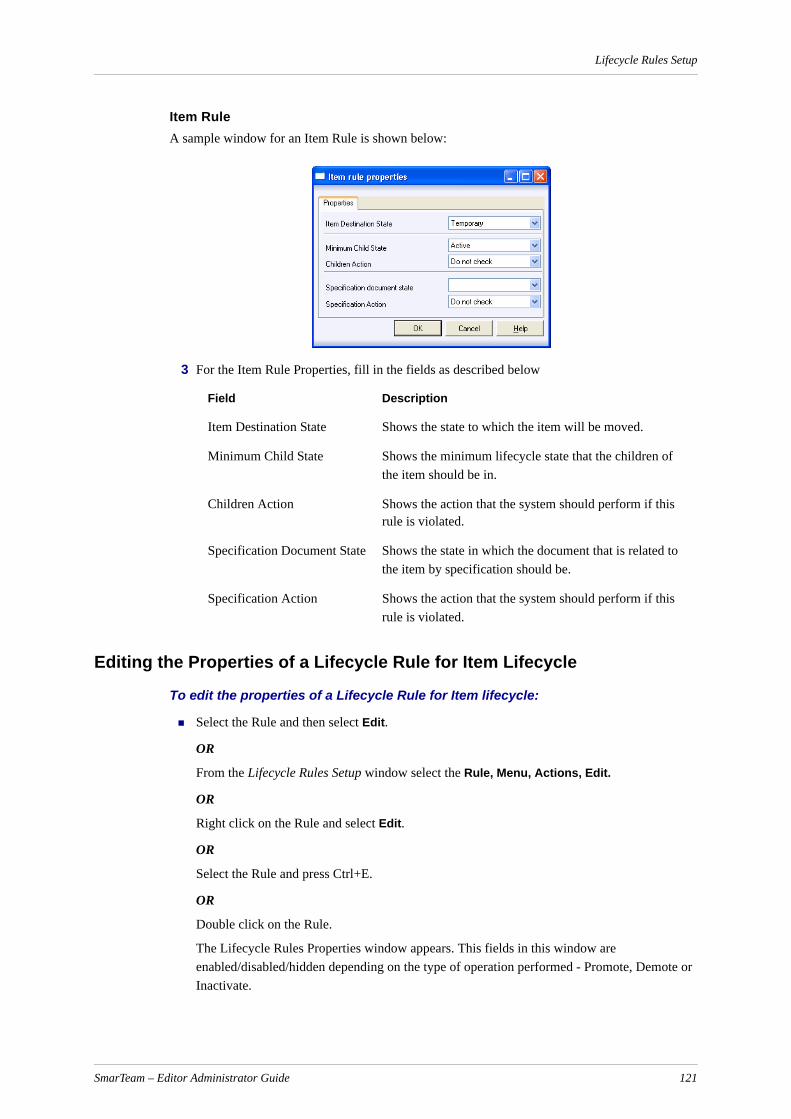
Lifecycle Rules Setup
Item RuleA sample window for an Item Rule is shown below:
3 For the Item Rule Properties, fill in the fields as described below
Editing the Properties of a Lifecycle Rule for Item Lifecycle
To edit the properties of a Lifecycle Rule for Item lifecycle:
Select the Rule and then select Edit.
OR
From the Lifecycle Rules Setup window select the Rule, Menu, Actions, Edit.
OR
Right click on the Rule and select Edit.
OR
Select the Rule and press Ctrl+E.
OR
Double click on the Rule.
The Lifecycle Rules Properties window appears. This fields in this window are enabled/disabled/hidden depending on the type of operation performed - Promote, Demote or Inactivate.
Field Description
Item Destination State Shows the state to which the item will be moved.
Minimum Child State Shows the minimum lifecycle state that the children of the item should be in.
Children Action Shows the action that the system should perform if this rule is violated.
Specification Document State Shows the state in which the document that is related to the item by specification should be.
Specification Action Shows the action that the system should perform if this rule is violated.
SmarTeam – Editor Administrator Guide 121

Lifecycle Rules Setup
Lifecycle Rules Properties - Promote Operation
The "Promote" operation promotes an Item revision in the ordered sequence of predefined lifecycle states, step by step.
Each Lifecycle rule for the Promote Operation comprises five criteria. The rule is created for the Item Destination State criteria. This criteria is shown in the first column of the rules list.
To define the rules for the Promote operation:
1 Select Lifecycle Rules Setup, Part Rules, Promote.
2 A list of lifecycle rules for the Promote operation is displayed.
3 You can add a new rule, edit existing rules or delete rules from this list as described in Editing the Properties of a Lifecycle Rule for Item Lifecycle.
The Item Rules Properties window for a Promote Operation is shown below:
Lifecycle Rules Properties - Demote Operation
Demote Rules are the opposite of Promote Rules. Due to this, Demote Rules are read-only and are created automatically from Promote Rules. Each time a user creates a Promote Rule, a corre-sponding Demote Rule is automatically created in the opposite direction.
Each Lifecycle rule for the Demote Operation comprises three criteria. The rule is created for the Item Destination State criteria. This criteria is shown in the first column of the rules list.
The Item Rules Properties window for a Demote Operation is shown below:
Note: The fields in this window are disabled and cannot be updated.
SmarTeam – Editor Administrator Guide 122

Lifecycle Rules Setup
Lifecycle Rules Properties - Inactivate Operation
Inactivate rules support propagation. In general, they work on objects in a similar manner to "Promote" operation.
Each Lifecycle rule for the Inactivate Operation comprises five criteria. The rule is created for the Item Original State criteria. This criteria is shown in the first column of the rules list.
The Item Rules Properties window for an Inactivate Operation is shown below:
Editing the Properties of a General/Integration Rule for Document Lifecycle
To edit the properties of a General/Integration Rule for Document Lifecycle:
Select the Rule and then select Edit.
OR
From the Lifecycle Rules Setup window select the Rule, Menu, Actions, Edit.
OR
Right click on the Rule and select Edit.
OR
Select the Rule and press Ctrl+E.
OR
Double click on the Rule.
The Lifecycle Rules Properties window appears:
SmarTeam – Editor Administrator Guide 123

Lifecycle Rules Setup
Note: For a general rule, the only editable fields are: Destination Operation, Link Operation, Switch to Latest, Propagation Allowed and Check Destination Object State.
Note: For an integration rule, the screen that appears depends on the type of integration. For some integrations, the Original Class/Destination Class fields are not displayed.
Testing a Lifecycle Rule for Document Lifecycle – EvaluateThe Rules Evaluation performs a simulation of the Lifecycle, i.e., it will show the destination lifecycle operation for any possible class and component type of the destination objects that could be linked to the original object by the selected link type.
By using Rules Evaluation the user will be able to see what exactly happens during the lifecycle.
To evaluate a rule:
Click the Evaluate button at the top of the lifecycle rules screen.
SmarTeam – Editor Administrator Guide 124

Lifecycle Rules Setup
Conflicts in Lifecycle Rules A user can define different Lifecycle Rules between the same classes or component types. In some cases, the rules may conflict with each other. For example, the destination operation depends on the class of specific object rather than on its component type.
The following is an example of a conflict:
One of the Integration Rules for a link class defines that for any component type, the destination operation on Check Out is Check Out.The user could add a custom rule for the same link class that defines that for origin class X and destination class Y, the destination operation on Check Out is Copy File. In this way the user causes a conflict between the integration and user-defined rules. The conflict here is that the integration rule, in spite of being defined for any component types, will not be applicative when the classes X and Y are involved in the lifecycle.
The Show Conflict feature of the application enables conflicts to be displayed.
To view conflicting rules:
Select the Show Conflict option.
Conflicts are marked on the screen by a red flag.
Lifecycle Setup for Document LifecycleThe Lifecycle Setup window allows you to add a description to each lifecycle state and operation, and to view the flow of lifecycle operations.
To access the Lifecycle Setup window:
From the Tools menu, select Lifecycle Setup.
The Lifecycle Setup window appears.
SmarTeam – Editor Administrator Guide 125

Lifecycle Rules Setup
This window contains three tabs:
Lifecycle States: This tab presents a list of the defined lifecycle states. To add a description for a state, select the state and enter a description in the State Description field.
Lifecycle Operations: This tab presents a list of the defined lifecycle operations. To add a description for an operation, select the operation and enter a description in the Operation Description field.
Lifecycle Graph: This tab presents a graphical flow of lifecycle operations.
Lifecycle Setup for Item Lifecycle - Item StatesThe Item States definition screen is used to define all types of item lifecycle states according to Enterprise Rules. Using this screen, you can define a sequence of lifecycle states, where each state signifies the maturity of the items at this point in their lifecycle.
The sequence is defined in a step-by-step process, where each progressive state defines a more mature state.
Any number of states can be defined in accordance to the organization’s rules.
The SmDemo database provides the following sequence of states:
SmarTeam – Editor Administrator Guide 126
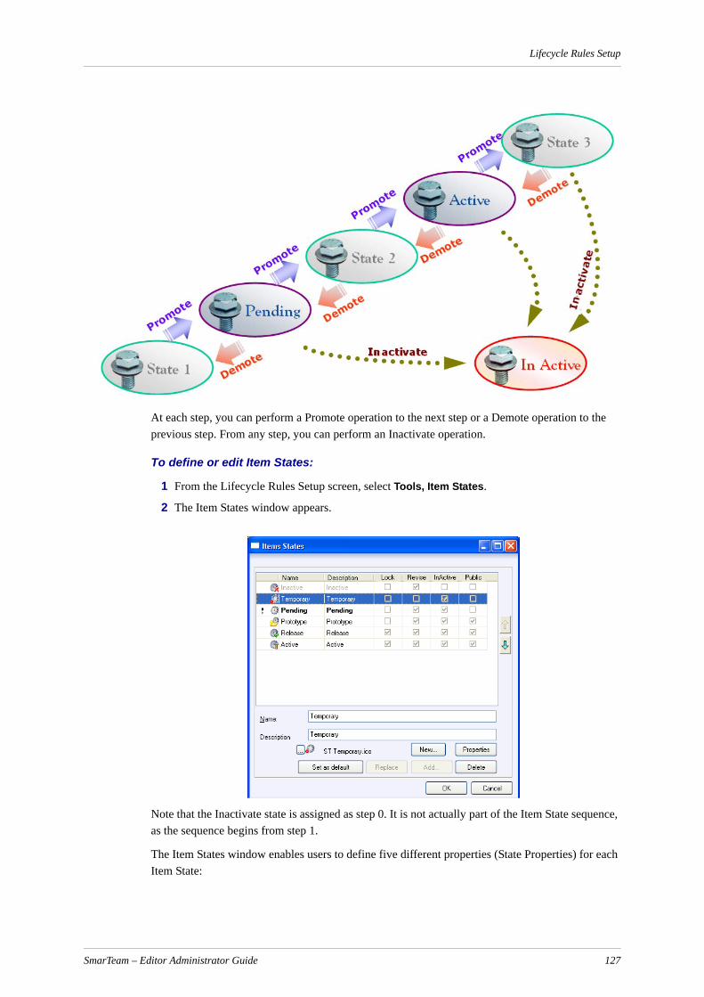
Lifecycle Rules Setup
At each step, you can perform a Promote operation to the next step or a Demote operation to the previous step. From any step, you can perform an Inactivate operation.
To define or edit Item States:
1 From the Lifecycle Rules Setup screen, select Tools, Item States.
2 The Item States window appears.
Note that the Inactivate state is assigned as step 0. It is not actually part of the Item State sequence, as the sequence begins from step 1.
The Item States window enables users to define five different properties (State Properties) for each Item State:
SmarTeam – Editor Administrator Guide 127
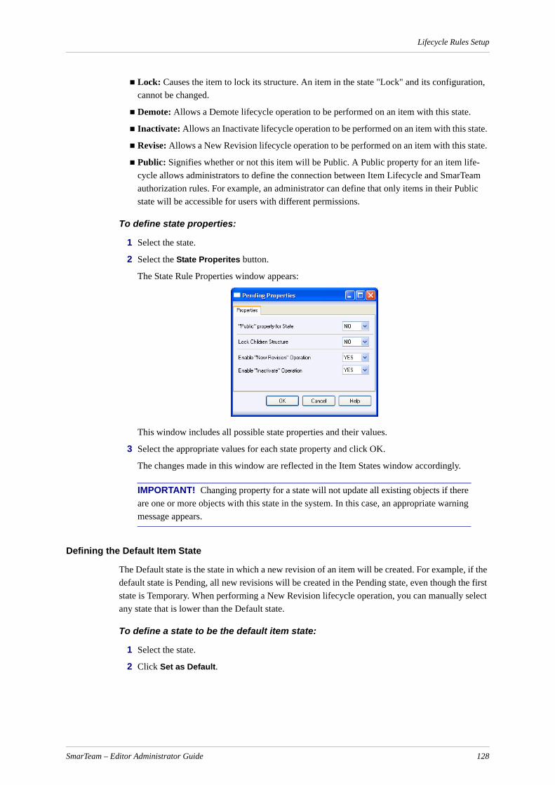
Lifecycle Rules Setup
Lock: Causes the item to lock its structure. An item in the state "Lock" and its configuration, cannot be changed.
Demote: Allows a Demote lifecycle operation to be performed on an item with this state.
Inactivate: Allows an Inactivate lifecycle operation to be performed on an item with this state.
Revise: Allows a New Revision lifecycle operation to be performed on an item with this state.
Public: Signifies whether or not this item will be Public. A Public property for an item life-cycle allows administrators to define the connection between Item Lifecycle and SmarTeam authorization rules. For example, an administrator can define that only items in their Public state will be accessible for users with different permissions.
To define state properties:
1 Select the state.
2 Select the State Properites button.
The State Rule Properties window appears:
This window includes all possible state properties and their values.
3 Select the appropriate values for each state property and click OK.
The changes made in this window are reflected in the Item States window accordingly.
IMPORTANT! Changing property for a state will not update all existing objects if there are one or more objects with this state in the system. In this case, an appropriate warning message appears.
Defining the Default Item State
The Default state is the state in which a new revision of an item will be created. For example, if the default state is Pending, all new revisions will be created in the Pending state, even though the first state is Temporary. When performing a New Revision lifecycle operation, you can manually select any state that is lower than the Default state.
To define a state to be the default item state:
1 Select the state.
2 Click Set as Default.
SmarTeam – Editor Administrator Guide 128
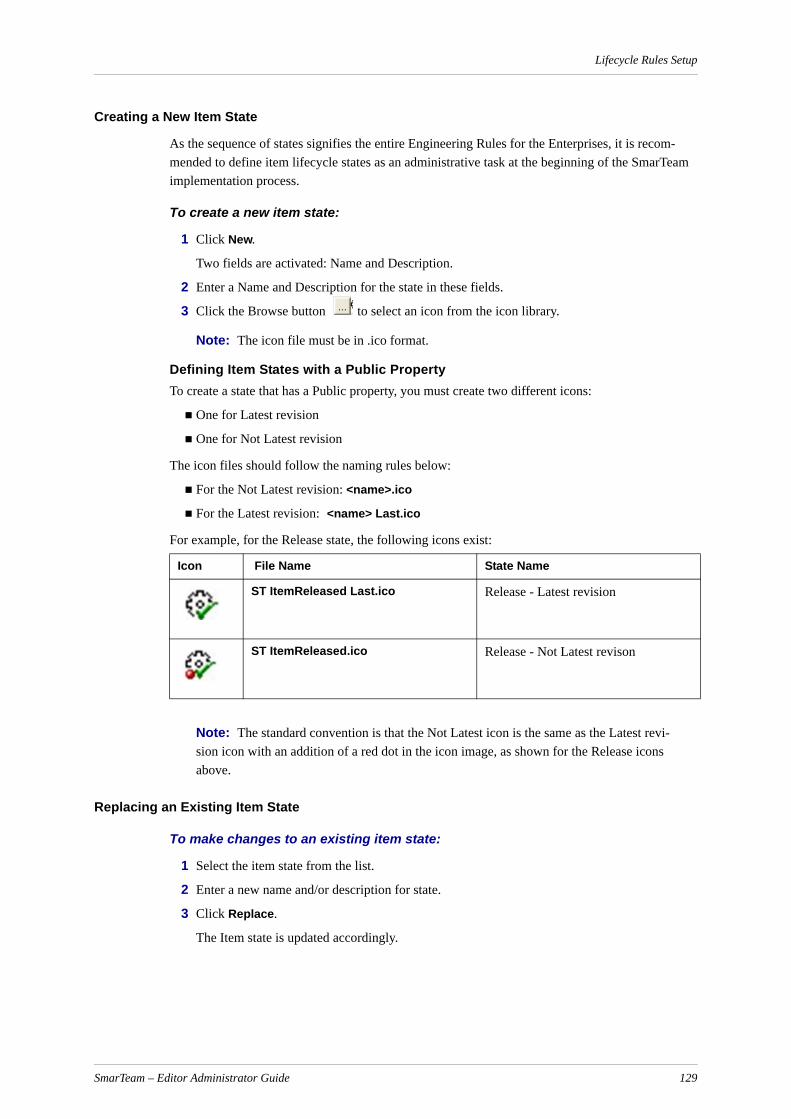
Lifecycle Rules Setup
Creating a New Item State
As the sequence of states signifies the entire Engineering Rules for the Enterprises, it is recom-mended to define item lifecycle states as an administrative task at the beginning of the SmarTeam implementation process.
To create a new item state:
1 Click New.
Two fields are activated: Name and Description.
2 Enter a Name and Description for the state in these fields.
3 Click the Browse button to select an icon from the icon library.
Note: The icon file must be in .ico format.
Defining Item States with a Public PropertyTo create a state that has a Public property, you must create two different icons:
One for Latest revision
One for Not Latest revision
The icon files should follow the naming rules below:
For the Not Latest revision: <name>.ico
For the Latest revision: <name> Last.ico
For example, for the Release state, the following icons exist:
Note: The standard convention is that the Not Latest icon is the same as the Latest revi-sion icon with an addition of a red dot in the icon image, as shown for the Release icons above.
Replacing an Existing Item State
To make changes to an existing item state:
1 Select the item state from the list.
2 Enter a new name and/or description for state.
3 Click Replace.
The Item state is updated accordingly.
Icon File Name State Name
ST ItemReleased Last.ico Release - Latest revision
ST ItemReleased.ico Release - Not Latest revison
SmarTeam – Editor Administrator Guide 129

Lifecycle Rules Setup
Deleting an Existing Item State
To delete an existing item state:
1 Select the item state.
2 Select Delete.
The item state is removed from the list.
Note: The state Inactivate cannot be deleted.
IMPORTANT! If there are one or more objects with this item state in the system, the item state cannot be deleted. In this case, an appropriate warning message appears.
Changing the Order of Item States
The order of the item states defines the sequence of states for the Promote and Demote operations.
To change the order of the item states:
1 Select an item state.
2 Use the Up/Down arrows to move the item state to its new position.
Go to State
The Go to State field in the Promote/Demote Lifecycle screen allows the user to jump directly to another state without going step-by-step through each state in the item lifecycle.
The Item State Transitions screen is used to define the states the states that will appear in the the Go to State field for each lifecycle operation.
To define the Go to State rules:
From the Lifecycle Rules Setup screen,. select Tools, Goto State.
The Item State Transitions screen appears:
SmarTeam – Editor Administrator Guide 130
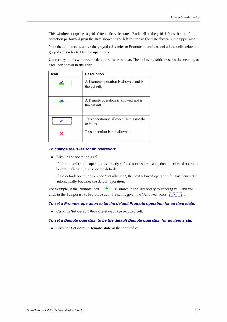
Lifecycle Rules Setup
This window comprises a grid of item lifecycle states. Each cell in the grid defines the rule for an operation performed from the state shown in the left column to the state shown in the upper row.
Note that all the cells above the grayed cells refer to Promote operations and all the cells below the grayed cells refer to Demote operations.
Upon entry to this window, the default rules are shown. The following table presents the meaning of each icon shown in the grid:
To change the rules for an operation:
Click in the operation’s cell.
If a Promote/Demote operation is already defined for this item state, then the clicked operation becomes allowed, but is not the default.
If the default operation is made "not allowed", the next allowed operation for this item state automatically becomes the default operation.
For example, if the Promote icon is shown in the Temporary to Pending cell, and you click in the Temporary to Prototype cell, the cell is given the "Allowed" icon .
To set a Promote operation to be the default Promote operation for an item state:
Click the Set default Promote state in the required cell.
To set a Demote operation to be the default Demote operation for an item state:
Click the Set default Demote state in the required cell.
Icon Description
A Promote operation is allowed and is the default.
A Demote operation is allowed and is the default.
This operation is allowed (but is not the default).
This operation is not allowed.
SmarTeam – Editor Administrator Guide 131

Process Management - Workflow Administration
Process Management - Workflow Administration
Designing a FlowchartThis section is intended for the system administrator.
Using SmarTeam - Workflow, any user can initiate and participate in an automated Process. A Process type is a specific workflow tailored to your company's work procedures, such as an ECO Process, an ECP Process and a Distribution Process.
Note: SmarTeam - Workflow provides Process types; such as ECP, ECO and Field Change. You can custom-design Process types using the SmarTeam Data Model Designer.
Each Process has a default workflow, or flowchart, and a Process can have additional workflows that can be chosen as well.
This section provides instructions for creating flowcharts. Using the Flowchart Designer, you can:
Design a new flowchart
Modify an existing flowchart
Add a new sub-flowchart
Load an existing sub-flowchart
Assign a flowchart to a Process type (e.g., ECO or ECP)
To design a flowchart, you simply define Nodes and add Connectors between the Nodes.
A Node is the basic element of a flowchart. It defines what actions should be performed and by whom, in order for the Process to proceed to the next step. Therefore, each Node is usually associated with one or more users and the tasks that should be performed.
A Connector directs the SmarTeam objects in a Process from Node to Node as the Process travels from start to finish.
Starting the Flowchart Designer
To start the flowchart designer:
1 From the taskbar Start button select Programs, SmarTeam, Administrative Tools then Flow-chart Designer .
The User Login window appears.
2 In the SmarTeam User Login window enter your assigned Login Name and Password and click OK. The Flowchart Designer window is displayed.
The Flowchart Designer window opens with a new flowchart containing a Start Node and End Node that cannot be deleted.
Note: Open an existing flowchart by clicking from the main toolbar. Start a new flowchart by clicking from the main toolbar.
SmarTeam – Editor Administrator Guide 132

Process Management - Workflow Administration
How to Design a FlowchartThis section describes the operations to be done, when creating a new flowchart and the elements of the flowchart involved.
Nodes
As you design a new flowchart or modify an existing one, you can add new Nodes. When you define a Node, you specify the users or groups that will receive the SmarTeam objects undergoing a Process and the tasks that the users must perform. During runtime, the users receive the Process in their Inbox, and they can carry out the assigned tasks, such as check out the SmarTeam objects or call the supplier.
The Flowchart Designer provides a Nodes Library in which you can store previously defined Nodes and their properties. You can drag any Node from the Nodes Library into a flowchart and modify its properties if necessary.
Note: You can also copy a Node from an existing flowchart into the current flowchart, using the standard Copy and Paste functions from the Edit menu. You can then modify the properties of the Node.
After you add a node, you can perform the following:
Assigning Users, Groups or Roles to a Node
Adding Regular Users or Groups to a Node
Adding CC (Read-only) Users or Groups to a Node
Opening a Node Properties WIndow
Defining Visual Properties of a Node
Assigning a Task to a Node
Assigning an Event to a Node
Assigning Additional Flow Properties to a Node
Adding a Connector
Using the Nodes Library
You can save Nodes in a Library in order to reuse them in another flowchart. You can define various folders in the Library to organize the Nodes. For example, you can create a folder for each depart-ment in your organization.
To open the library area:
From the View menu choose View Library.
The library area is displayed to the left of the design area in the Flowchart Designer window.
To add a node to the library:
Drag the Node from the current flowchart to the Library. (There must be a defined library folder to add/drag a Node into it.) All the properties of the Node are saved together with the Node.
SmarTeam – Editor Administrator Guide 133

Process Management - Workflow Administration
To copy a Node from the Library:
Drag the Node from the Library to the flowchart. You can then modify its properties.
Adding a Node
To add a node:
1 Open an existing flowchart or create a new flowchart.
2 From the Flowchart toolbar, choose Add Node.
3 In the flowchart, position the cursor in the location where you want to add the Node.
Note: You can resize or move the Node at any time. First, select the Node with the Select tool. You can then move the Node or resize it by dragging on one of its handles.
4 You can now define the properties of the Node.
Assigning Users, Groups or Roles to a Node
To assign users, groups or roles to a node:
1 In the Flowchart Designer, double-click on the node to display the Properties window.
2 Click the Flow tab to display the Flow properties.
3 In the To field, click the button to display the Regular Node Users window.
4 In this window, click the Add New.... button.
The Select Users/Groups window is displayed.
Adding Regular Users or Groups to a Node
To add regular users or groups to a node:
1 Type the name in the Type Name field;
OR
From the displayed list, double-click on a name to select and move it to the To field;
OR
Select the name and click .
The selected Users/Groups are added to the To: field.
Adding CC (Read-only) Users or Groups to a Node
To add CC (Read-only) users or groups to a node:
1 Type the name in the Type Name field;
OR
Double-click on a name to select and move it to the Cc field;
OR
Select the name and click .
The selected Users/Groups are added to the Cc: field.
If more than one User/Group is added in the section To add regular users or groups to a node:, you must set a policy as follows:
SmarTeam – Editor Administrator Guide 134
Process Management - Workflow Administration
a Choose All Users (And) if you wish to assign each User/Group listed in the New Node Users window to this Node. During runtime, each of the listed User/Group will receive the SmarTeam objects and must respond.
Note: If you choose the All Users (And) policy, you cannot define SmarTeam – Editor lifecycle operations for this Node.
b Choose Any User (Or) to allow any one of the Users/Groups listed in the New Node Users window to respond to this Node. During runtime, the User/Group that captures the SmarTeam objects in the Process (by clicking the Capture button) is assigned the task at this Node.
c If you check Modify list of Executors at run time you do not need to enter any users in the window. During runtime, the user at the previous Node selects the user(s) for this Node.
Note: If you define a Distribution Node and you do not check Select Users at Run time, you must assign at least one regular (To) user.
d Select a user and click Set As Delegator to assign a user who will be able to delegate a task to other users.
e Click Clear Delegator to clear a previously delegated user.
2 Click OK to close the Regular Node Users window.
Opening a Node Properties WIndow
To open a node properties window:
Double-click on the Node or select the Node and choose Properties from the View menu. The Properties window is displayed.
The Node Properties window is divided into three tabs:
Defining Visual Properties of a Node
To define visual properties of a node:
1 Click the Visual tab in the Properties window to display the Visual properties of a Node.
2 Define the appearance of the Node by filling in the Visual properties, as listed below.
Tab Description
Flow Define the users assigned to this Node, the tasks to be performed on this Node, and a time limit, etc.
Event Define operations that occur automatically, such as Before/After/On Send/ Receive/Open Events.
Visual Define the appearance of the Node, such as its color and size.
Property Description How To
Alignment Define the alignment of the bitmap in the Node.
Click in the Alignment field to display a drop-down arrow Click the arrow to display a dropdown list of alignment types, and select one.
SmarTeam – Editor Administrator Guide 135

Process Management - Workflow Administration
Auto Size Define the size of the Node when it is first added to the flow-chart.
Click in the Auto Size field to display a drop-down arrow . Click the arrow to display a dropdown list of Automatic Node sizing method, and select one.
Color Define the back-ground color of the Node.
Click in the Color field to display a dropdown arrow . Click the arrow to display a drop-down list of background colors, and select one.
Description Provide a description of the Node.
Click in the Description field and enter descriptive text which will be displayed on the Node Icon.
Font Define the font type on the Node.
Click in the Font field to display a selection button . Click the selection button to display a standard font selection window. Choose a font and click OK.
Height Define the height of the Node.
Click in the Height field and enter the height of the Node . You can use the arrows to incrementally adjust the position.
Image Choose a bitmap for the Node.
Click in the Image field to display a selection button . Click the selection button to display a standard selection window. Choose a bitmap, and click OK.
Left Define the horizontal position of the Node in the flowchart.
Click in the Left field and enter the horizontal position of the Node. You can use the arrows to incrementally adjust the position.
Line Style Define the line style for the Node.
Click in the Line Style field to display a drop-down arrow . Click the arrow to display a dropdown list of line styles, and select one.
Name Define the Node's name.
Click in the Name field and enter a name for the Node.
Shape Define the shape of the Node.
Click in the Shape field to display a dropdown arrow . Click the arrow to display a drop-down list of shapes, and select one.
Top Define the vertical position of the Node in the flowchart.
Click in the Top field and enter the vertical position of the Node. You can use the arrows
to incrementally adjust the position.
Width Define the width of the Node.
Click in the Width field and enter the width of the Node. You can use the arrows to incrementally adjust the width.
Property Description How To
SmarTeam – Editor Administrator Guide 136
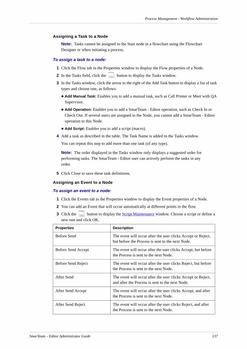
Process Management - Workflow Administration
Assigning a Task to a Node
Note: Tasks cannot be assigned to the Start node in a flowchart using the Flowchart Designer or when initiating a process.
To assign a task to a node:
1 Click the Flow tab in the Properties window to display the Flow properties of a Node.
2 In the Tasks field, click the button to display the Tasks window.
3 In the Tasks window, click the arrow to the right of the Add Task button to display a list of task types and choose one, as follows:
Add Manual Task: Enables you to add a manual task, such as Call Printer or Meet with QA Supervisor.
Add Operation: Enables you to add a SmarTeam - Editor operation, such as Check In or Check Out. If several users are assigned to the Node, you cannot add a SmarTeam - Editor operation to this Node.
Add Script: Enables you to add a script (macro).
4 Add a task as described in the table. The Task Name is added to the Tasks window.
You can repeat this step to add more than one task (of any type).
Note: The order displayed in the Tasks window only displays a suggested order for performing tasks. The SmarTeam - Editor user can actively perform the tasks in any order.
5 Click Close to save these task definitions.
Assigning an Event to a Node
To assign an event to a node:
1 Click the Events tab in the Properties window to display the Event properties of a Node.
2 You can add an Event that will occur automatically at different points in the flow.
3 Click the button to display the Script Maintenance window. Choose a script or define a new one and click OK.
Properties Description
Before Send The event will occur after the user clicks Accept or Reject, but before the Process is sent to the next Node.
Before Send Accept The event will occur after the user clicks Accept, but before the Process is sent to the next Node.
Before Send Reject The event will occur after the user clicks Reject, but before the Process is sent to the next Node.
After Send The event will occur after the user clicks Accept or Reject, and after the Process is sent to the next Node.
After Send Accept The event will occur after the user clicks Accept, and after the Process is sent to the next Node.
After Send Reject The event will occur after the user clicks Reject, and after the Process is sent to the next Node.
SmarTeam – Editor Administrator Guide 137

Process Management - Workflow Administration
Assigning Additional Flow Properties to a NodeYou can assign a time limit and levels of importance to a Node.
Note: The time limit and level of importance are displayed next to each Process in a user's SmartBox. This enables the user to logically progress through the Processes assigned to him or her.
You can also define whether the Node is obligatory or not. If the Node is obligatory, SmarTeam - Workflow will route the Process to this Node even if the users do not.
To assign additional flow properties to a node:
1 Click the Flow tab in the Properties window to display the Flow properties.
2 In the Importance field, click the dropdown arrow to assign a level of importance to this task.
3 In the Obligatory field, click the dropdown arrow and choose True or False.
4 In the Node Time Limit field, fill in the number of days, hours and minutes allocated to compile the task.
5 In the Preliminary Alert field, enter a number of days, hours and minutes for scheduling a Preliminary Alert notification prior to the approaching time limit of a node.
6 In the Alerted Users field, select the users who will receive alert messages regarding the node. Click in an available User field to display a dropdown arrow , and then select True or False.
Connectors
Adding a Connector
To add a connector:
1 Open an existing flowchart or create a new flowchart.
2 From the Flowchart toolbar, choose Add Connector . (The cursor changes to a hand.)
3 In the flowchart, position the cursor in the location where you wish to add the Connector. Click and drag to insert a connecting arrow between two Nodes. Make sure the Connector touches both Nodes.
Note: You can resize or move the Connector at any time. First, select the Connector with the Select tool. You can then move the Connector or resize it by dragging on one of its handles.
You can now define the properties of the Connector.
On Receive The event will occur as soon as the Process arrives at a user's SmartBox.
OnOpen The event will occur each time the user opens the Process in the SmartBox
Properties Description
SmarTeam – Editor Administrator Guide 138
Process Management - Workflow Administration
To open the connector properties window:
1 Double click on the Connector or select the Connector and choose Properties from the View menu. The Connector Properties window is displayed.
2 Select and click a tab to define its properties as follows:
Defining Response Names
To define response names:
1 From the Workflow menu, choose Responses to display the Responses window.
2 Click Add to define Response Names (or click Update to modify a Response Name). The Add Responses window is displayed.
3 In the Name field, enter a name for the Response. In the Type field, choose a Response Type (Accept Response or Reject Response). Click OK.
The new Response Name is added to the Responses window. You can repeat steps 2 and 3 several times to add several Response Names.
4 You can choose a default Response Name by selecting a Response Name and clicking Set Default. Each time you add a new Connector, the default Response Name is assigned to the new Connector.
5 Click OK.
After you design a logical flowchart, you must choose one or more Processes for the flowchart. When a SmarTeam - Editor user initiates a workflow, the user first chooses a Process. The default flowchart for the Process is displayed. The user can also choose one of the other flowcharts assigned to that Process.
Note: During the setup of SmarTeam – Workflow, Process names are defined (using the Data Model Designer), such as an ECO Process, an ECP Process and a Distribution Process.
After you assign a Process to a flowchart, choose Save from the File menu. The Flowchart Designer checks the viability of the flowchart.
If the flowchart is logical, the flowchart is now available to SmarTeam - Editor users.
If the flowchart is not logical, an error message is displayed. You must then redesign the flow-chart. For example, if the flowchart does not flow from Start to End, or creates an illogical loop, it is not viable.
Note: It is advisable to assign a flowchart to a Process after the flowchart is viable. If you assign an incomplete flowchart to a Process, and then choose Save, an error is displayed and the flowchart cannot be saved. This error occurs because SmarTeam - Workflow checks the viability of the flowchart during a Save operation only after the flowchart has been assigned to a Process.
Tab Description
Visual Define the appearance of the Connector on the flowchart, such as its color and width.
Flow Define the Response Name of the Connector.
SmarTeam – Editor Administrator Guide 139

Process Management - Workflow Administration
The Flowchart Designer enables you to assign a flowchart to a Process type in two ways:
Assign a Process to a flowchart: Define the Processes for the selected flowchart.
Assign a flowchart to a Process: Define the flowcharts for the selected Process.
Note: A default flowchart must be chosen for each Process.
To assign a response name to a connector:
1 Click the Flow tab in the Properties window.
2 In the Response field, click the dropdown arrow to display a list of Response Names. By default, the Flowchart Designer provides three Response Names:
Accept
Reject
Review
Note: If you wish to add more Response Names to the list, or modify a Response Name, you must open the Responses window by choosing Responses from the Workflow menu.
Defining Visual Properties of a Connector
To define visual properties of a connector:
1 Click the Visual tab in the Properties window to display the Visual properties of a Connector.
2 Define the appearance of the Connector by filling in the visual properties, as listed below:
Property Description How To
Font Define the font type on the Node.
Click in the Font field to display a selection button . Click the selection button to display a standard font selection window. Choose a font and click OK.
Line Style Define the style of the line.
Click in the Line Style field to display a drop-down arrow . Click the arrow to display a dropdown list of line styles, and select one.
Name Define the name of the Connector as displayed in the flowchart.
Click in the Name field and enter a name for the Connector.
Style Define the style of the arrow.
Click in the Style field to display a dropdown arrow . Click the arrow to display a drop-down list of styles, and select one.
Width Define the width of the Connector
Click in the Width field and enter the width of the Connector. You can use the arrows to incre-mentally adjust the width
SmarTeam – Editor Administrator Guide 140

Process Management - Workflow Administration
Flowcharts
Opening the Flowchart Properties Window
To open the flowchart properties window:
1 From the View menu, choose Properties to display the Flowchart Properties window.
Note: Check that none of the Nodes or Connectors in the flowchart is selected. If a Node or Connector is selected, then the Properties window for the selected object is displayed, rather than the Properties window for the flowchart.
Note: To display the Properties window at all times, choose Properties Always on Top from the View menu.
2 Click the Flow or Visual tabs to define their properties as follows:
Assigning an Event to a Flowchart
To activate a script when attaching/detaching an object to a process:
1 Click the Events tab in the Properties window to display the Event properties of a Node.
You can add an Event that will occur automatically at different points in the flow.
2 Click the button to display the Script Maintenance window. Choose a script or define a new one and click OK.
Note: These hooks should be defined for the default flowchart and any other flowchart attached to the process as needed.
Choosing Different Flowchart Options before Handling a Process
To choose different flowchart options:
1 Right-click anywhere in the flowchart to display the dropdown menu.
2 From the dropdown menu, select Flowchart Options to display the Flowchart Options window.
Tab Description
Flow Define a supervisor, a time limit, a default reject response as well as the Process to which the flowchart will be assigned.
Visual Define the general appearance of the flow-chart, such as its background color and grid properties.
Properties Description
Before Attach Object The event will occur before an object is attached to a process that is based on this flowchart.
After Attach Object The event will occur after an object is attached to a process that is based on this flowchart.
Before Detach Object The event will occur before an object is detached from a process that is based on this flowchart.
After Detach Object The event will occur after an object is detached from a process that is based on this flowchart.
SmarTeam – Editor Administrator Guide 141

Process Management - Workflow Administration
3 In the Supervisor field, click on the Browse button to select a Supervisor.
4 In the Links tab page, click in the applicable checkbox to link an object’s children, related objects or CFOs to the Process, as described below.
5 In the Security tab page:
a Click in the Enable flow security checkbox if you want to prevent running SmarTeam operations on objects connected to the process. When unchecked, SmarTeam operations can be run on objects connected to the process.
b Click in the Enable flow sharing checkbox to enable objects connected to the process to be shared with another process. When unchecked, objects connected to the current process cannot be connected to another process.
6 In the Alerts tab page:
a Check the Enable alert mechanism radio button to enable the sending of alerts when a process has not been completed according to schedule. If this radio button is not checked, no alerts will be sent. The Administrator can change the options for node and process alert times at any stage. The alert mechanism does not perform a check on nodes that have already passed.
b In the Time Limit field, fill in the number of days, hours and minutes allocated to compile the task.
c In the Preliminary Alert field, enter a number of days, hours and minutes for scheduling a Preliminary Alert notification prior to the approaching time limit of a node.
d In the Alert Interval field, enter the interval between the SmarTeam – Workflow server checks for overdue processes and nodes. Once a day, all alert messages regarding the delay in completion of a process or node are sent.
e Select whether to send the alert to the Supervisor or the Initiator of the process.
7 Click OK for the selected options to be included in the process.
Assigning a Flowchart to a Process
To assign a flowchart to a process:
1 From the Workflow menu, choose Process Assignment to display the Process Assignment window. A list of SmarTeam - Workflow Processes are displayed:
2 Select a Process and click Assign to display a list of flowcharts.
3 Check one or more flowcharts in the list. These flowcharts will be added to the Process selected in step 2.
Link children to process Provides the same security restrictions to the children of the participating objects, as selected from the Security tab page.
Link related objects to process Provides the same security restrictions to the related objects participating in the process, as selected from the Security tab page.
Link Common File Objects (CFO) to process
Provides the same security restrictions for all CFOs participating in the process.
SmarTeam – Editor Administrator Guide 142

Process Management - Workflow Administration
4 You can choose a default flowchart for a Process by selecting a flowchart and clicking the Set Default button. Keep in mind that one flowchart must be set as the default for a Process.
5 Click OK.
Assigning a Process to the Current Flowchart
To assign a process to the current flowchart:
1 Choose Properties from the View menu to display the Flow Properties window.
2 In the Assign to Process field, click the selection button to display the Process Assignment window. A list of Processes is displayed that were previously defined during the setup of SmarTeam - Workflow.
3 Check the Process(es) to which the flowchart will be assigned.
For example: You can now assign the current flowchart to the ECO Process. When a user initiates a flow and chooses the ECO Process, the flowchart currently selected will be listed among the flowcharts that the user can choose.
4 If you wish to define the current flowchart as the default flowchart for users, check the Set as default checkbox for the ECO Process. When a user initiates a flow and chooses the ECO Process, the current flowchart is automatically displayed as the default flowchart for the Process.
Note: The flowchart shown in the Flow Process is for the root process only. Nested processes, sub-processes and other types of hierarchy are not shown in the Flow Process.
Selecting a Flowchart for the Process
To choose a different flowchart for the process:
1 Right-click anywhere in the flowchart. From the dropdown menu, choose Change Flowchart.
2 From the displayed list, choose a new flowchart for the Process.
Using the Workflow Manager
Introduction
This section is intended for the supervisor or system administrator.
The Workflow Manager provides online viewing and monitoring capabilities for Processes that have been initiated. Using the Workflow Manager search tools, you can locate Processes that are problematic or causing delays in the flow. You can then modify a Process on-the-fly, by reassigning Nodes and tasks.
The Workflow Manager provides the following tools:
Search tools to identify Processes. These search tools include a Quick Search which enables you to define search criteria by choosing predefined options as well as a general search.
Online viewing of statistics generated by the Workflow Manager.
On-the-fly modification of a Process by:
reassigning a Node
deleting a Process
SmarTeam – Editor Administrator Guide 143

Process Management - Workflow Administration
Thus, the Workflow Manager is a powerful tool enabling you to monitor all Processes in your orga-nization and resolve any bottlenecks that may occur.
Accessing the Workflow Manager
From the Workflow Manager, you can locate Processes and adjust Processes on-the-fly. All Work-flow Manager functions are accessible from the main window.
To access the workflow manager:
1 From the Admin Console, select Workflow Management and then Workflow Manager. The SmarTeam User Login window appears.
The Workflow Manager window is displayed.
2 Click an icon for the function you require.
Workflow Manager provides the following tools:
Running a Quick Search
The Workflow Manager provides a tailor made Quick Search function in which search attributes are predefined: Simply choose the search criteria you wish to use.
Processes that match selected search criteria are displayed in a search results list. From the search results lists, you may select a Process and perform the following:
View a Process
Open a Process
Delete a Process
Reassign a Process
Terminate a Process
Note: The more attributes of a Process that are selected in defining the search, the more precise the search results will be.
Searching By Attribute
The Workflow Manager enables you to search for a specific Process or a range of Processes that have common attributes. Processes that match selected search criteria are displayed in a search results list.
From the search results lists, you may select a Process and perform the following:
View a Process
Open a Process
Search Enables you to search for a Process by attribute.
Quick Search Enables you to quickly search for a Process according to predefined criteria.
Statistics Enables you to view statistics of selected Processes.
Select User Enables you to select a User to display the selected User's SmartBox. You can then modify one of the User's Processes.
SmarTeam – Editor Administrator Guide 144

Process Management - Workflow Administration
Delete a Process
Reassign a Process
Terminate a Process
Note: The more attributes of a Process that are selected in defining the search, the more precise the search results will be.
Modifying a Process
The Workflow Manager provides ease and flexibility in modifying a Process. The Workflow Manager enables you to modify Processes on-the-fly, reassign a Process to any user, terminate Processes and delete Processes.
For example, if a user is on vacation, you can reassign a task to another user simply by entering the absent user’s SmartBox, selecting the task and assigning the task elsewhere.
The Workflow Manager provides the following two ways to open and modify a Process:
Run a search: From the search results list, select a Process and modify it.
Log in to the Workflow Manager as the administrator or supervisor of the process. From the user’s SmartBox, select a Process and modify it.
Note: After a Workflow Process has been initiated, it cannot be deleted from the SmarTeam system until it is completed or terminated. However, a System Administrator can permanently delete a process using Workflow Server administrative utility.
Viewing Statistics
The Workflow Manager generates statistics which reflect the status of Processes in flow. For each type of Process the average timespan is displayed. This enables you to plan your workflow accordingly.
To view statistics:
1 From the Workflow Manager window, click . The Workflow Manager Statistics window is displayed.
2 Click Close.
Setting Alert Options in the Workflow Manager
The Alert properties settings are added to the Flowchart Options window and the Node Alert Options window.
The alert mechanism can be activated, deactivated or modified using the Workflow Manager. For example, you can check or uncheck the Enable Alert Mechanism.
SmarTeam – Editor Administrator Guide 145

Process Management - Workflow Administration
To set the values for alerts in the Workflow Manager:
Use the following fields.
Setting the Alerted Users
Flowchart designer allows you to select default users who will be alerted.
For a past-due process, the alert message can be sent to:
the process supervisor
the process initiator
For a past-due node, the alert message can be sent to:
Process supervisor
Process initiator
Property Description How To
Enable Alert mecha-nism
Define whether alerts will be sent to provide notification of processes that are past due.
In the Flowchart Alert Options window, select the Enable Alert mech-anism radio button.When the alert mechanism has been enabled for the process, the Node Alert Options window will display an Alert mechanism enabled message,
Time Limit Define the time limitation for the process or for the node.
Click in the Time Limit field. Enter the time limitation for completing the process/node, using the d:hh:mm:ss format.
Preliminary Alert Define the interval for sending notification about the pending time limit for completion of a process or a node.
Click in the Preliminary Alert field. Using the d:hh:mm:ss format, enter the amount of time (before the process deadline) at which the preliminary alert will be sent.
Alert Interval Defines the time interval between the SmarTeam - Work-flow server checks for overdue processes and nodes. Once a day, all alert messages regarding the delay in comple-tion of a process or node are sent.
Click in the Alert Interval field. Enter the time interval for the checking of overdue processes or nodes.
Send Alert To… Define which users should receive the Preliminary Alert and the Periodic Alerts. Select:• Supervisor• Initiator• Node users• Senders
The list of users who will receive the alerts differs for processes and for nodes. To select the users who will receive the alerts, click in an available field to display a dropdown arrow. Choose True or False.
SmarTeam – Editor Administrator Guide 146

Process Management - Workflow Administration
Users of the current and/or pending node
Users of the previous node (senders)
When the Alert mechanism completes a round of checking, it will compile a single alert notification to be sent to the supervisor or initiator. The message will contain information on all related past due processes and nodes.
Setting Up the SmarTeam - Workflow ServerThe Flow Server utilities enable you to set up and run the Flow Server for your network. After the Flow Server utilities are installed, the Flow Service is automatically installed on the computer designated as the server, and it runs transparently in the background. From the Control Panel, you can open the standard Services window, which lists the services currently installed. After installa-tion, the Flow Service is displayed among the other services.
Tip: Keep in mind that special permissions must be defined for the Flow Service, after the installa-tion process (using standard Windows procedures).
The Flow Server controls the flow of Processes between users in the SmarTeam - Workflow envi-ronment. The Flow Server constantly monitors the database at predefined time intervals and checks whether any Process is ready to be moved to the next user (node). The administrator can determine the following parameters:
The databases that the Flow Server will monitor.
The time intervals that the Flow Server will check a specific database.
The number of work threads used by the Flow Server to a specific database. The more work threads assigned, the faster the processing speed.
The services that the Flow Service is dependent upon. These services run transparently in the background in conjunction with the Flow Service.
For more information, see the following sections:
Modify Database Details Window
Preparing the Flow Server Environment - provides instructions for preparing the proper users and permissions needed for the installation process.
Installing the Flow Service- provides instructions for installing the Flow Service in the server’s computer.
Maintaining the Flow Server - provides instructions for running the Server Setup utility on the designated server computer.
Workflow Server Details Window
The Workflow Server Details window displays the name of the computer designated as the server.
You can modify the displayed name and click OK.
Modify Database Details Window
In the Modify Database Details Window, you can modify the Flow Server parameters to suit the requirements of your network:
The Audit Time Period. The time intervals between audit checks of the database can be modified.
SmarTeam – Editor Administrator Guide 147
Process Management - Workflow Administration
To enable the alert mechanism for the workflow, select the Alert Enable option. If this option is not checked, no alert procedures will be performed.
Upon initiation of a new process, the initiator can change the alert options for the entire process and for any of the nodes.When the Alerts mechanism is enabled for the process, the user at the current node can change the alert options for the following node(s).
The Alert Check Interval Time field lets you set the interval at which the server sends alerts.
Note: Smart Web Editor Server - Enter the URL for the SmarTeam - Web Editor for the specific database. This allows the user to open the process using a Web browser. If this property is defined, a hyperlink to the problematic process will be added to the e-mail messages that are sent.
Preparing the Flow Server Environment
The following utilities are needed to install and maintain the Flow Server. Some of these files work automatically in the background; others must be run so that you can define specific parameters. These utilities (.exe files) are installed in the SmarTeam/Bin directory by default.
To ensure a smooth installation of the Flow Server utilities, check that a user account is defined which will serve as the Flow Service user.
Installing the Flow Service
The Flow Service must be installed on the same computer that is designated as the Flow Server. When you install the Flow Service, you can determine:
The services that the Flow Service is dependent upon, meaning those services that will run in conjunction with the Flow Service.
The User Name and password for the Service.
Utility Purpose
SetupWorkflow Service.exe Runs the Service Setup utility which enables you to define the following parameters:• The Services that are dependent on the Flow Service. • A user name and password for the Service.
FlowServerSetup.exe Runs the Server Setup utility which enables you to define:• The databases that the Flow Server monitors.• The time intervals (audit time) at which the Flow Server
monitors a specific database.• The number of work threads used by the Flow Server to
process the information.
WorkflowCapsule.exe The operating system runs this utility when the Service is started.
WorkflowServer.exe This utility is invoked by the WorkflowCapsule utility. It implements the audit process and connects the threads to the database. This utility actually implements the Flow Server operation.
SmarTeam – Editor Administrator Guide 148

Process Management - Workflow Administration
Maintaining the Flow Server
The Flow Setup utility enables you to set up the Flow Server to monitor selected SmarTeam data-bases. The FlowSetup.exe file is installed in the SmarTeam/Bin directory by default.
The Flow Server controls the flow of Processes between users in the SmarTeam - Workflow envi-ronment. The Flow Server constantly monitors the database at predefined time intervals and checks whether any Process has been completed and is ready to be moved to the next user. The checking frequency is established by the systems administrator using the Flow Setup utility. When a Process is found to be ready to be moved to the next user, it is moved by the Flow Server.
The maintenance of the Flow Server is done in the following four basic steps:
Step 1: Run the Flow Setup Utility
Step 2: Choose a Database
Step 3: Define Monitoring Properties
Step 4: Maintain Alert Messages
Note: In order to make the maintenance declarations effective, you must start the Flow Service only after changes are complete. If the Flow Service is already running before changes are done, then the changes will be in affect only after the service is stopped and re-started in the Microsoft Services window.
Step 1: Run the Flow Setup UtilityIn this step, the Flow Setup utility is activated for the local/host computer and displays the current Flow Server configuration.
To run the flow setup utility:
1 In the SmarTeam/Bin directory, double-click Flowserversetup.exe.
The local computer is designated to act as the Server.
2 You can modify the Server name as follows:
Right-click on the branch and choose Modify.
In the displayed window, enter a new server name and click OK.
Step 2: Choose a DatabaseThis step describes how to select a database that the Flow Server will monitor. You can repeat this step several times to add databases.
To add a database:
1 From the Server menu, choose New Database.
OR
2 Right-click on and choose New Database.
The Available Databases window is displayed.
3 Select the required database and click OK. The selected database is displayed below the icon in the Workflow Server Setup window.
Each time you select the database, its properties are displayed on the right.
SmarTeam – Editor Administrator Guide 149

Process Management - Workflow Administration
Step 3: Define Monitoring PropertiesThis step describes how the Flow Server parameters can be modified to suit the requirements of your network:
The Audit Time Period. The time intervals between audit checks of the database can be modified.
The number of Work Threads per database. To increase processing speed, you can increase the number of work threads that the Flow Server will use.
Step 4: Maintain Alert Messages
To setup the alert mechanism for SmarTeam - Workflow:
1 Launch the Workflow Server setup by running FlowServerSetup.exe. The Workflow Setup window opens.
2 From the database tree, select a database.
3 Right-click on the database and select Update Database from the dropdown menu.
OR
From the Database menu, select Update Database.
The Modify Database Details window opens.
To define the settings for alerts:
1 Enable the alerts mechanism by clicking the Alert Enable radio button.
2 Enter the interval for alert checks by typing or by clicking the up or down arrows.
3 Specify the location of the SmarTeam Web Editor server.
4 Click OK to confirm the settings.
Starting the Flow Service
Before the Flow Service can begin to monitor the databases, you must activate the Flow Service, as described below.
To startup the Flow Service:
1 From the Control Panel, click Services. The Microsoft Services window is displayed.
2 Select the Flow Service and click Start.
Setting SmarTeam Preferences
Using the Workflow Server setup, you can define whether a given server should perform the Alert procedure and at what periods.
Setting SmarTeam - Workflow Administrator Options
To set the Workflow Administrator options:
1 From the main menu, select Tools, Administrator Options and then click Workflow Options. The SmarTeam - Workflow Options window opens.
SmarTeam – Editor Administrator Guide 150

Process Management - Workflow Administration
2 In the Alert Mechanism area, use the following fields to set the values for the SmarTeam - Workflow Options window:
To ensure that the Workflow Server will work, you must do the following:
Check the Use Workflow Server option
Define one or both options in the Alert mechanism tab: Time Before, Alert Interval.
Setting Flowchart Designer Options
To set the Flowchart Designer options:
1 The Alert properties settings are added to the Properties window of the flowchart (process) or the node:
Property Description How To
Send alert as SmarTeam message Define whether to send the alert as a SmarTeam message which will arrive in the user’s SmartBox.
Select the checkbox to activate this option.
Send alert as e mail Define whether to send the alert as an e-mail message which will arrive in the user’s Inbox.
Select the checkbox to activate this option.
Time Before Define the interval for sending notification about the pending time limit for completion of a process or a node.
Click in the Time Before field. Using the d:hh:mm:ss format, enter the amount of time (before the process deadline) at which the preliminary alert will be sent.
Alert Interval Define the interval between the SmarTeam - Workflow server checks for overdue processes and nodes.
Once a day, all alert messages regarding the delay in comple-tion of a process or node are sent.
Click in the Alert Interval field. Enter the time interval between the SmarTeam - Workflow server checks for overdue processes and nodes.
Send Alert To… Define which users should receive the Preliminary Alert and the Periodic Alerts. Select:
• Supervisor• Initiator• Node users• Senders
The list of users who will receive the alerts differs for processes and for nodes. To select the users who will receive the alerts, mark the appropriate checkboxes.
SmarTeam – Editor Administrator Guide 151
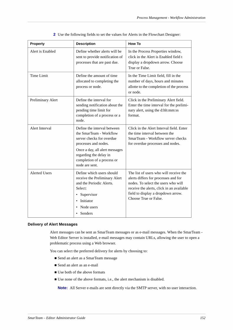
Process Management - Workflow Administration
2 Use the following fields to set the values for Alerts in the Flowchart Designer:
Delivery of Alert Messages
Alert messages can be sent as SmarTeam messages or as e-mail messages. When the SmarTeam - Web Editor Server is installed, e-mail messages may contain URLs, allowing the user to open a problematic process using a Web browser.
You can select the preferred delivery for alerts by choosing to:
Send an alert as a SmarTeam message
Send an alert as an e-mail
Use both of the above formats
Use none of the above formats, i.e., the alert mechanism is disabled.
Note: All Server e-mails are sent directly via the SMTP server, with no user interaction.
Property Description How To
Alert is Enabled Define whether alerts will be sent to provide notification of processes that are past due.
In the Process Properties window, click in the Alert is Enabled field t display a dropdown arrow. Choose True or False.
Time Limit Define the amount of time allocated to completing the process or node.
In the Time Limit field, fill in the number of days, hours and minutes allotte to the completion of the process or node.
Preliminary Alert Define the interval for sending notification about the pending time limit for completion of a process or a node.
Click in the Preliminary Alert field. Enter the time interval for the prelimi-nary alert, using the d:hh:mm:ss format.
Alert Interval Define the interval between the SmarTeam - Workflow server checks for overdue processes and nodes. Once a day, all alert messages regarding the delay in completion of a process or node are sent.
Click in the Alert Interval field. Enter the time interval between the SmarTeam - Workflow server checks for overdue processes and nodes.
Alerted Users Define which users should receive the Preliminary Alert and the Periodic Alerts. Select:• Supervisor• Initiator• Node users• Senders
The list of users who will receive the alerts differs for processes and for nodes. To select the users who will receive the alerts, click in an available field to display a dropdown arrow. Choose True or False.
SmarTeam – Editor Administrator Guide 152
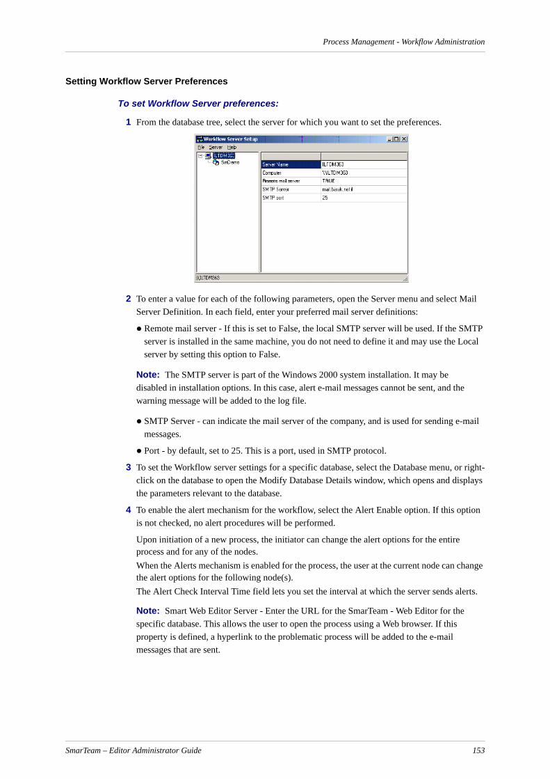
Process Management - Workflow Administration
Setting Workflow Server Preferences
To set Workflow Server preferences:
1 From the database tree, select the server for which you want to set the preferences.
2 To enter a value for each of the following parameters, open the Server menu and select Mail Server Definition. In each field, enter your preferred mail server definitions:
Remote mail server - If this is set to False, the local SMTP server will be used. If the SMTP server is installed in the same machine, you do not need to define it and may use the Local server by setting this option to False.
Note: The SMTP server is part of the Windows 2000 system installation. It may be disabled in installation options. In this case, alert e-mail messages cannot be sent, and the warning message will be added to the log file.
SMTP Server - can indicate the mail server of the company, and is used for sending e-mail messages.
Port - by default, set to 25. This is a port, used in SMTP protocol.
3 To set the Workflow server settings for a specific database, select the Database menu, or right-click on the database to open the Modify Database Details window, which opens and displays the parameters relevant to the database.
4 To enable the alert mechanism for the workflow, select the Alert Enable option. If this option is not checked, no alert procedures will be performed.
Upon initiation of a new process, the initiator can change the alert options for the entire process and for any of the nodes.When the Alerts mechanism is enabled for the process, the user at the current node can change the alert options for the following node(s).The Alert Check Interval Time field lets you set the interval at which the server sends alerts.
Note: Smart Web Editor Server - Enter the URL for the SmarTeam - Web Editor for the specific database. This allows the user to open the process using a Web browser. If this property is defined, a hyperlink to the problematic process will be added to the e-mail messages that are sent.
SmarTeam – Editor Administrator Guide 153

Process Management - Workflow Administration
Working with the Workflow Server
Installing the Flow Service
To install the flow service:
1 Double-click on the SetupWorkflowService.exe.
The Available list box lists the services that are currently installed on your server.
The Selected list box lists the services that must be invoked before the Flow Service.
The User Name and Password refer to the Flow Service user.
2 Select the services that enable access to the databases that the Flow Server will monitor and move these services into the Selected list box.
3 In the Account Name field, enter the user account for the Flow Service. Be sure to include the domain name when necessary. In the Password field, enter the password of the user.
4 Use the following syntax: <domain>\<accountname> for the account name. If the account is a local account, then use the following syntax: \\<computer>\<accountname>.
Note: Keep in mind that the assigned user must be a member of the local Administrators group.
5 Click Install to install the Flow Service.
Assign Permissions to the Flow Service User
This procedure is performed after installing the Flow Server utilities.
To assign permissions to the flow service user:
1 From the Programs menu, point to Administrative Tools and choose User Manager. The User Manager window is displayed.
2 From the Policies menu, choose User Rights to display the User Rights Policy window.
3 Check the Show Advanced User Rights checkbox.
4 Click on the dropdown arrow next to the Right field and choose Log on as a Service. Click OK.
The Grant To list box displays the User/Group that will receive the selected user right. The name of the Flow Service user (or the Group that the user belongs to) should be displayed.If the appropriate User/Group is not displayed in the Grant To list box, click Add to display a list of Users/Groups. Select the Flow Service user and click OK. The Flow Service user name is displayed in the Grant To list box.
5 Click on the dropdown arrow next to the Right field and repeat the above steps for Act as part of the operating system and Increase Quotas.
Modifying Monitoring Properties
To modify monitoring properties:
1 From the Database menu, select Modify.
OR
Right-click on the Database and choose Modify from the popup menu.
SmarTeam – Editor Administrator Guide 154
Process Management - Workflow Administration
The Modify Database Details window is displayed
2 In the displayed window, you can define:
The audit time intervals, in seconds.
The number of work threads.
3 Click OK.
Workflow System Configuration Parameters
useViewSecurity
This key is used to allow operations on an attached object to be performed according to the authori-zations defined for the user.
Possible values:
TRUE = SmarTeam support for View Object Security while working with a flow process is enabled. In this case, the user can only execute operations on attached objects if he has the appropriate authorizations defined in SmarTeam.
FALSE (Default) = SmarTeam support for View Object Security while working with a flow process is enabled. This results in backward compatibility.
The useViewSecurity preference is located in the smarteam.std.workFlow.config.xml file and can be accessed using the Find option of the System Configuration Editor.
SmarTeam – Editor Administrator Guide 155

Administrator Options
Administrator OptionsThe Administrator Options function enables the System Administrator to define general system defaults as well as individual defaults.
If you are an Administrator who also logs on to SmarTeam – Editor as a user, you must be careful when changing these settings. Changing the settings via the Administrator Options window will affect SmarTeam – Editor for all users.
The following options are available for modification:
Option Description
Conversion Formats
Enables you to change the format of the Date, Time and Time Stamp in SmarTeam – Editor.
General Enables you to define whether a linked object will inherit a revision state or not.
Lifecycle Enables you to define various revision defaults. See Lifecycle and File Operations Report for details.
Workflow Options
Enables you to define various options when SmarTeam – Workflow is integrated within SmarTeam – Editor.
User Account Options
Enables you to configure password and LDAP options.
Views Configuration
Enables you to configure different views in SmarTeam – Editor. See Configuring SmarTeam Views for details.
SmarTeam – Editor Administrator Guide 156

Administrator Options
Conversion FormatsConversion Formats enables you to modify the default view of the date, time and time stamp as it appears in your SmarTeam – Editor desktop. These formats affect only the SmarTeam – Editor application of the logged-in user. (This option can also be set by the user via the Tools, Options… menu.)
To define Conversion Formats:
1 From the SmarTeam – Editor main menu select Tools then sub-menu Administrator Options… to display the Administrator Options window.
2 In the Conversion Formats section, click Format Options… to display the Conversion Formats window.
The default formats (as displayed in the Profile card) appear in their applicable field – Time Stamp, Date and Time – in the Conversion Formats window.
3 To change a format, click on the dropdown arrow and enter a new format. For example, to change the Date format to dd/mm/yyyy (such as, 23/01/1999) instead of the displayed format.
4 Click OK to save your changes – or click Cancel to abort any changes made – and to close the Conversion Formats window.
5 In the Administrator Options window, click Close to exit.
GeneralThe General option enables you to determine whether a linked object can inherit a revision state or not inherit a revision state. This option determines a system-wide value and is only available to the System Administrator.
To define General Preferences:
1 From the SmarTeam – Editor main menu select Tools then sub-menu Administrator Options to display the Administrator Options window.
2 In the General section, click General Options… to display the General Preferences window.
SmarTeam – Editor Administrator Guide 157

Administrator Options
3 Click in the applicable checkbox for the option you want to select.
Use only UNC directory names
Check this option if you want the directory and vault browser to automatically convert the drive-based logical path for mapped drives into UNC paths. (For example, instead of mapping a drive [h] to a specific computer and directory, when you check this option the following parameters will appear: \\server1\[directory_name].)
Delete attached files when deleting object
When a user selects to delete an object, check this option to enable the user to decide whether to delete a file that is attached to the object.
Inherit state of composition
Check this option to enable SmarTeam – Editor to change the state of a linked object. If this option is checked, the state of links will be inherited from the root object.
This option is for hierarchical links only.
Note: For a link between a part and design table, the link state always remains New and cannot be updated by changing any parameter.
In searches, by default retrieve only last public revisions
When checked, by default, only the last public revisions are retrieved when running a search.
Time Stamps calculated relative to database server time
When checked, SmarTeam – Editor uses the time from the server when creating and updating objects. When SmarTeam – Editor is launched, the client station reads the time from the server and calculates the difference in time between the client station and the server. SmarTeam – Editor uses this time difference to calculate the server time whenever a new object is created/updated.
When unchecked, SmarTeam – Editor uses the time from the client station for the date field when creating and updating objects.
Calculate client to server time difference every [x] hours
The interval by which SmarTeam – Editor calculates the difference between server time and the client station time.
SmarTeam – Editor Administrator Guide 158
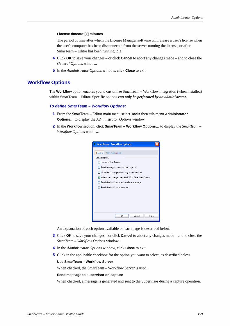
Administrator Options
License timeout [x] minutes
The period of time after which the License Manager software will release a user's license when the user's computer has been disconnected from the server running the license, or after SmarTeam – Editor has been running idle.
4 Click OK to save your changes – or click Cancel to abort any changes made – and to close the General Options window.
5 In the Administrator Options window, click Close to exit.
Workflow OptionsThe Workflow option enables you to customize SmarTeam – Workflow integration (when installed) within SmarTeam – Editor. Specific options can only be performed by an administrator.
To define SmarTeam – Workflow Options:
1 From the SmarTeam – Editor main menu select Tools then sub-menu Administrator Options… to display the Administrator Options window.
2 In the Workflow section, click SmarTeam – Workflow Options… to display the SmarTeam – Workflow Options window.
An explanation of each option available on each page is described below.
3 Click OK to save your changes – or click Cancel to abort any changes made – and to close the SmarTeam – Workflow Options window.
4 In the Administrator Options window, click Close to exit.
5 Click in the applicable checkbox for the option you want to select, as described below.
Use SmarTeam – Workflow Server
When checked, the SmarTeam – Workflow Server is used.
Send message to supervisor on capture
When checked, a message is generated and sent to the Supervisor during a capture operation.
SmarTeam – Editor Administrator Guide 159
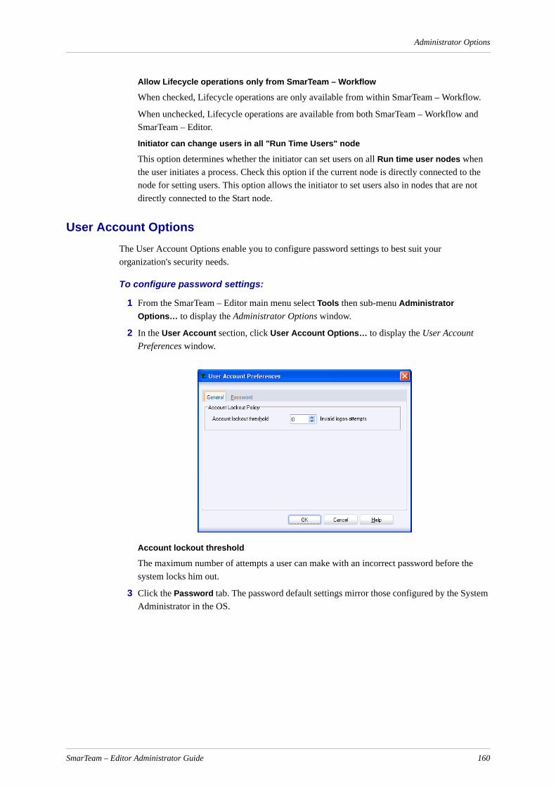
Administrator Options
Allow Lifecycle operations only from SmarTeam – Workflow
When checked, Lifecycle operations are only available from within SmarTeam – Workflow.
When unchecked, Lifecycle operations are available from both SmarTeam – Workflow and SmarTeam – Editor.
Initiator can change users in all "Run Time Users" node
This option determines whether the initiator can set users on all Run time user nodes when the user initiates a process. Check this option if the current node is directly connected to the node for setting users. This option allows the initiator to set users also in nodes that are not directly connected to the Start node.
User Account OptionsThe User Account Options enable you to configure password settings to best suit your organization's security needs.
To configure password settings:
1 From the SmarTeam – Editor main menu select Tools then sub-menu Administrator Options… to display the Administrator Options window.
2 In the User Account section, click User Account Options… to display the User Account Preferences window.
Account lockout threshold
The maximum number of attempts a user can make with an incorrect password before the system locks him out.
3 Click the Password tab. The password default settings mirror those configured by the System Administrator in the OS.
SmarTeam – Editor Administrator Guide 160

Administrator Options
Minimum password length
The minimum number of characters permitted in passwords.
Minimum password age
The interval, measured in days, between password expiry and the time the system queries the user if he wants to change his password.
Maximum password age
The maximum interval, measured in days, that a password can be valid, inclusive of date of change.
Passwords must meet complexity requirements
If checked, new passwords are verified to ensure that they are different from previous passwords used and that the user's login, user name or last names are not somehow included.
Allow plain text
By default, this option is checked, allowing non-coded and/or non-hashed passwords, which are inherently less secure.
4 Click OK to save your changes – or click Cancel to abort any changes made – and to close the User Account Preferences window.
Note: When configuring any of the User Account Management keys in the System Configuration Editor (listed below), the Domain Level must be selected as the Override level:
UserAccountManagement.AccountLockoutThresholdUserAccountManagement.MinimumPasswordLengthUserAccountManagement.MaximumPasswordAgeUserAccountManagement.PasswordAlgorithmUserAccountManagement.NoLastPasswordUserAccountManagement.AllowPlainTextUserAccountManagement.AuthenticationAttributeNameUserAccountManagement.NoUserNameInPasswordUserAccountManagement.MinimumPasswordAge
SmarTeam – Editor Administrator Guide 161

Administrator Options
Vault Selection
This option becomes enabled if the SmarTeam system has the Vault Replication mechanism installed. In this case, the SmarTeam Administrator must select the vault to be used in a Multi-site or Multi-vault environment.
To select a Vault:
1 From the main menu, select Tools, Options, Lifecycle Options.
The Lifecycle Options dialog box appears.
2 In the General tab, select the vault name from the combo box.
3 Click OK.
SmarTeam – Editor Administrator Guide 162

Mail Configuration
SmarTeam – Editor Administrator Guide 163
Mail ConfigurationSmarTeam – Editor enables users to send email to other SmarTeam users via the SmartBox, Lotus Notes (Versions 5.0 - 6.5), or the default mail program.
Lotus Notes can be used for sending mail after activation of the UseLotusNotes system configuration key. This key is defined at the Domain, Machine or User level.
To configure SmarTeam – Editor for using Lotus Notes:
1 Using the System Configuration Editor, assign a value for the following key:
<useLotusNotes>
This key may be assigned one of the following values:
Note: To send an email, a SmarTeam – Workflow license must be available and SmarTeam – Workflow must be installed.
False (default setting) Lotus Notes is not used, and the default mail program is active.
True Lotus Notes is used, and the default mail program is deactivated.

Script Maintenance
Script MaintenanceAn event is an operation, or function, which takes place in SmarTeam – Editor. The Script Maintenance utility enables you to modify operations (functions) in SmarTeam – Editor, by adding a macro, or script, before, after or instead of a default SmarTeam – Editor operation. For example, you can modify an operation so that before a drawing is added to SmarTeam – Editor, a message is displayed; or, after a customer's Profile card is updated, the customer's balance is displayed.
The Script Maintenance utility also enables you to define a new operation in SmarTeam – Editor. For example, you may want to add a Report function that prints the links of an object. The Report function will then be added to the SmarTeam – Editor main menu and accessed when you select Actions, sub-menu User Defined Tools.
In order to modify a SmarTeam – Editor operation or add a new operation, you must attach a macro to the selected operation. You can select an existing macro from a script or create a new macro by modifying a script.
Note: When a new script is added to any Class, a User Defined Command should also be created in the Menu Editor utility for the new script.
After defining a script, it must be connected to the SmarTeam system. This is done using hooks. For details on the process of defining script hooks and the different types of script hooks available, refer to Client-side Hooks for Client-based Applications.pdf and Server-side Hooks for Server-based Applications.pdf.
You can also access the Script Maintenance utility by:
Opening the Script Maintenance standalone utility, as described on the following page.
Selecting the Script Maintenance option from the SmarTeam – Editor Tools menu. (When you display the Script Maintenance window from within SmarTeam – Editor, you will have to exit and re-enter SmarTeam – Editor in order to implement the changes.)
From the Form Designer utility, in order to add a macro that takes place when the user clicks in the Profile Card.
From the Import utility, in order to modify or filter an import process.
The following operating instructions are provided:
Running the Script Maintenance Utility
Modifying a SmarTeam Event
Modifying a Script
Assigning a Script to the Login Screen
Adding a Script to the Integration Save Operation
Running the Script Maintenance Utility
To open the Script Maintenance utility:
1 From the taskbar Start select Programs, SmarTeam, Administrative Tools, Admin Console.
2 From the Application Tools group, select Script Maintenance.
The SmarTeam User Login window appears.
3 Enter your User name and Password, if necessary then click on the OK button.
SmarTeam – Editor Administrator Guide 164

Script Maintenance
After successful login, the Script Maintenance window opens.
The left pane displays SmarTeam Classes and Links as defined during setup. The right pane displays a grid of SmarTeam – Editor operations and cells in which you can modify a System or User Defined operation by attaching a macro before, after or instead of the default SmarTeam operation.
Modifying a SmarTeam Event
To modify a SmarTeam event:
1 In the Script Maintenance window, select a Class or Link to display its operations.
2 Double-click in the Before/After/Instead cell in the grid, next to the SmarTeam event you want to modify to display the Script Browser window.
OR
Select the cell in the appropriate grid and click the Assign button to display the Script Browser window.
OR
Select the cell in the appropriate grid and from the menu select Scripts, sub-menu Assign to display the Script Browser window.
Assign Opens the Script Browser window. You can also double-click in a cell to open the Script Browser window, or from the menu select Scripts, sub-menu Assign.
Clear Clears a macro from the selected cell in the grid. You can also select Scripts from the menu, then sub-menu Clear.
Delete Deletes a user defined operation. (Only enabled when the User Defined page is selected.)
User Defined
Select this page to add a completely new and independent operation to SmarTeam – Editor. This new operation is not linked to any existing operation. Refer to User-Defined Operations.
SmarTeam – Editor Administrator Guide 165
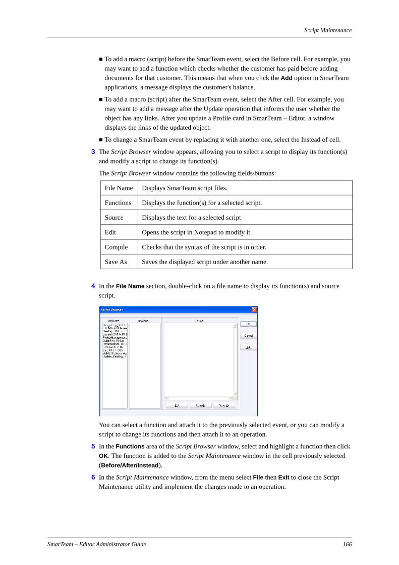
Script Maintenance
To add a macro (script) before the SmarTeam event, select the Before cell. For example, you may want to add a function which checks whether the customer has paid before adding documents for that customer. This means that when you click the Add option in SmarTeam applications, a message displays the customer's balance.
To add a macro (script) after the SmarTeam event, select the After cell. For example, you may want to add a message after the Update operation that informs the user whether the object has any links. After you update a Profile card in SmarTeam – Editor, a window displays the links of the updated object.
To change a SmarTeam event by replacing it with another one, select the Instead of cell.
3 The Script Browser window appears, allowing you to select a script to display its function(s) and modify a script to change its function(s).
The Script Browser window contains the following fields/buttons:
4 In the File Name section, double-click on a file name to display its function(s) and source script.
You can select a function and attach it to the previously selected event, or you can modify a script to change its functions and then attach it to an operation.
5 In the Functions area of the Script Browser window, select and highlight a function then click OK. The function is added to the Script Maintenance window in the cell previously selected (Before/After/Instead).
6 In the Script Maintenance window, from the menu select File then Exit to close the Script Maintenance utility and implement the changes made to an operation.
File Name Displays SmarTeam script files.
Functions Displays the function(s) for a selected script.
Source Displays the text for a selected script
Edit Opens the script in Notepad to modify it.
Compile Checks that the syntax of the script is in order.
Save As Saves the displayed script under another name.
SmarTeam – Editor Administrator Guide 166

Script Maintenance
Note: If you opened the Script Maintenance window from within the SmarTeam application (by selecting Script Maintenance from the Admin Console) , exit and re-enter SmarTeam – Editor in order to implement the changes.
Limitations
The existing hook of Before Delete Process does not work. If a script is attached, it will be ignored.
Modifying a ScriptThis section describes how to modify a script in order to change its functions. You can then select one of these functions and attach it to an event in the Script Maintenance window.
To modify a script:
1 In the Script Browser window, select a file and click Edit to display the script in the SmartScript Editor. The SmartScript Editor is a script editing interface which enables you to edit the script and modify its functions.
2 Using the same syntax as displayed in the script, you can modify the script by adding, deleting or replacing a function. From the SmartScript Editor File menu, select Save and Exit to return to the Script Browser window.
3 In the Script Browser window, the Functions field displays the modified functions of the script. You can check the syntax of the script by clicking the Compile button. If the syntax is incorrect, a warning message is displayed.
4 In the Script Browser window, select a function and click OK. The function is added to the Script Maintenance window in the previously selected cell (Before/After/Instead).
5 In the Script Maintenance window, from the menu select File then Exit to close the Script Maintenance utility and implement the changes made to an operation.
Note: If you opened the Script Maintenance window from within the SmarTeam – Editor application (by selecting Tools, Configuration Options, Script Maintenance), exit and re-enter SmarTeam – Editor in order to implement the above changes.
Assigning a Script to the Login Screen
To assign a script to the Login Screen:
1 In the Script Maintenance window highlight the Class Browser node in the Class Tree and select the Before or After field of the On Login operation.
2 Click Assign to open the Script Browser window.
3 Double-click on a file name to display its functions and its script.
When SmarTeam – Editor activates a script, it automatically passes the arguments:
ApplHndl, SelectOp, RecLst1, RecLst2, and RecLst3
to the script. Both scripts receive in the first record list the login name of the user in the element "LOGIN" (NM_LOGIN).
In the Before script, in the third record list, you can return to the SmarTeam – Editor login name and password, or just the user's login name. To return to the SmarTeam – Editor login
SmarTeam – Editor Administrator Guide 167

Script Maintenance
name and password, add to the third record list elements of typeTDMT_CHAR "LOGIN" (NM_LOGIN) and "PASSWORD" (NM_PASSWORD) with appropriate values. SmarTeam – Editor will check the authorization of the user. If the user is authorized, the application will run without displaying the Login window. If the user is not authorized, or if the login name was not returned from the Before script, the Login window will be displayed.
The After script can be used to perform additional checks of user logins:
In case the After script returns the result state of not equal to: Err_NONE (0), a user will not gain access to SmarTeam – Editor automatically and the Login window will be opened. Subsequently, the user reenters his/her name (and password), and the After script will be called again.
Notes:
a The User Login value shown in the status bar cannot be changed using a user defined script.
b For further information about programming SmarTeam scripts, refer to the SmarTeam API COM Reference Guide.
Adding a Script to the Integration Save OperationYou can also add a script to the Save operation in an integration. This is done using the <integration>.CALL_SCRIPT key.
Note: CALL_SCRIPT is invoked when the system configuration key BasicScript.Enabled is set to True.
The script receives the following record lists as parameters:
File Description (Input parameter) - A record list that the integration sends to SmCad when calling a Save operation
Classes List (Input parameter) - A list of classes that may be used to save a document of the type that is being saved
Out Classes List (Output parameter) - A list of classes that will be used instead of the Classes List during the Save operation.
To define a script for the Integration Save operation:
1 In the Script Maintenance Utility, define a user-defined script
2 In the System Configuration Editor, set the script name in the key <integration>.CALL_SCRIPT, where <integration> is the name of the specific integration.
SmarTeam – Editor Administrator Guide 168

User-Defined Operations
User-Defined OperationsIn addition to modifying an existing SmarTeam event (by adding a macro before, after or instead of the existing event), SmarTeam – Editor enables you to add a new, independent event. This new operation will be displayed in the SmarTeam – Editor main menu when selecting Actions, User Defined Tools.
For the User Defined Tools option to appear when you right-click a document, define the option in the Menu Editor by performing the following procedure.
1. Open the Menu Editor.
2. Add a new Menu Item in the drop-down menu or pop-up menu
3. Define the command by navigating to Menu Commands (SmarTeam), Standard Commands, select User Defined Tools command.
4. Define Name for Menu Item , e.g. User Defined Tools.
5. Click OK.
Adding a User-Defined Operation
To add a user-defined operation to SmarTeam – Editor:
1 In the Script Maintenance window, click on the User Defined tab to display the User Defined page.
The left pane displays a list of SmarTeam Classes, as defined during setup. The right pane displays the Operation column to enter the name of a new operation, and the Function Name column to enter the function name (macro) that the operation will perform.
2 In the Operation column, enter a name to identify the operation you want to create. This operation name will be displayed in the SmarTeam – Editor main menu when you select Actions, User Defined Tools.
3 Double-click in the Function Name box next to the new operation name, or in the menu bar click Assign to open the Script Browser window.
4 In the Script Browser window, double-click on a file from the File Name field to display its function(s) and script.
In the Functions area of the Script Browser window, select a function, or edit the script to create a new function.
5 In the Script Browser window, click OK to attach the selected function to the new operation.
The selected function now appears in the Script Maintenance window in the previously selected Function Name field.
SmarTeam – Editor Administrator Guide 169

User-Defined Operations
6 If necessary, repeat the above steps to add additional user defined events.
7 To remove a function from the Function Name field, select the function then select Clear from the main menu.
8 To remove/change an operation name from the Operation field, simply select the name then press Delete/Backspace on your keyboard, and/or overwrite with a new name.
9 After adding user defined event(s), in the Script Maintenance window select File, Exit to close the Script Maintenance utility and implement the changes made to an operation.
The defined operation, BOMExcel, will be displayed and accessed from the SmarTeam – Editor main menu when selecting Actions, User Defined Tools.
To delete a user-defined operation from SmarTeam – Editor:
1 In the Script Maintenance window, click on the User Defined tab to display the User Defined page.
2 In the Operation column select and highlight the operation name you want to delete.
3 In the menu bar, click on the Delete button to delete the selected user-defined operation.
4 From the menu select File then sub-menu Exit to close the Script Maintenance window and implement your change. The deleted operation will only be removed from the main menu after exiting and then starting SmarTeam – Editor.
SmarTeam – Editor Administrator Guide 170
Sequence Designer
Sequence DesignerThe Sequence Designer utility enables you to create and modify masks. A mask is a formula by which SmarTeam – Editor will increment a number automatically in a specific field in the Profile Card. The most common usage of a mask is for the primary ID number of a Class and the revision number. When a user opens a new Profile card in SmarTeam – Editor, the field that was defined as a mask will automatically display a new number based on the formula defined by the Sequence Designer utility.
For example, you might define a mask name as Proj-999 for the Project ID field: Each time a new project is added to SmarTeam – Editor, a new number will automatically be incremented in SmarTeam – Editor as follows, Proj-001, Proj-002 and so on.
When a mask is defined to a class, it will be inherited to the child classes when no mask is defined for the child classes.
The Sequence Designer utility can also be accessed via the following utilities:
Form Designer – in order to create or modify a field in the Profile card for which a mask is generated.
Import – in order to assign a mask as an import source.
The following operating instructions are provided:
Launching the Sequence Designer
Creating a Mask
Launching the Sequence Designer
To launch the Sequence Designer:
1 From the taskbar Start button select Programs, SmarTeam, Admin Console, Sequence Designer.
2 The SmarTeam User Login window now appears. Enter your User name and Password, if necessary then click OK for your entries to be accepted and to close the window.
SmarTeam – Editor Administrator Guide 171

Sequence Designer
3 After successful login, the Sequence Designer window opens, listing Classes and their attributes.
4 Select an attribute for linking a mask. In the right pane the Sequence name, Sequence description, Sequence pattern and Current value fields appear. If a mask has already been linked to the selected attribute, the previously-defined mask is displayed in these fields.
Note: The fields are described in Creating a Mask.
5 Click the Link button to create a new mask or modify an existing mask. The Sequence Selection Dialog window is displayed.
OR
Click the Clear button to detach the displayed mask from the selected attribute. All mask fields are cleared.
OR
Click Close to save any changes made and exit the Sequence Designer utility.
6 After clicking Link, the Sequence Selection Dialog window is displayed, listing the selected previously defined mask names.
The Sequence List area displays a list of previously-defined masks. The Description and Mask Pattern are displayed for each Mask Name.
Note: If the attribute selected in the Sequence Designer window has a mask linked to it, the Sequence Selection Dialog window automatically displays the selected mask. If the attribute selected in the Sequence Designer window does not have a mask linked to it, the New Masks window is displayed without any defined values.
Creating a MaskIn the Sequence Selection Dialog window, you can:
Create a new mask
Modify a mask
SmarTeam – Editor Administrator Guide 172

Sequence Designer
Delete a previously defined mask
Modify the range of a mask
To create a new mask:
1 In the Sequence Selection Dialog window click New to display the Edit Sequences window.
2 Click on the Sequence Info tab and enter values for the fields as described below.
Sequence name
Enter a name for the mask.
Sequence description
Enter a description for the mask. (This field is optional.)
Sequence pattern
Enter the formula by which SmarTeam – Editor will increment the numbers in this field. Use the characters a and 9. The character a represents alphabetical increments. The character 9 represents numerical increments.
For example: The Mask DOC-999 means that SmarTeam – Editor will increment the field as follows, DOC-001, DOC-002, and so on.
The mask A9 means that SmarTeam – Editor will increment the field as follows: A0, A1, A9, B0, B1 and so on.
Note: To modify the range of the formula, click the Pattern Info tab at the top of the window. Refer to Modifying the Range of a Mask.
Check Pattern
Click on the Check Pattern button to view how the mask will be incremented.
Sequence value
Enter the baseline value and click the Set button. The mask formula will generate numbers starting from this value.
Click the Increment button to increment the value for this field, and to view the incrementation pattern defined in the Sequence Pattern field.
SmarTeam – Editor Administrator Guide 173

Sequence Designer
Check Value
Click on the Check Value button to check for syntax errors.
Revision mode
When this mask is for a revision field, check the Revision mode checkbox. When this field is checked, the formula placed in the Mask field must contain a separator, such as a.9.
Separator
When Revision mode is checked, the Separator field displays a selection of separators. This list displays suggestions only.
Group
When Revision mode is checked, the Group field is active and displays the number of variables (with a separator) displayed in the Mask field. For example, for the mask a.9.9, a 3 is displayed in the Group field.
3 Click OK to save the entered mask details. Note that the mask has not yet been linked to any attribute.
4 If you decide not proceed with creating this new mask, click Close to return to the Sequence Selection Dialog window without saving the entered mask details.
5 After saving the new mask, click Close to return to the Sequence Selection Dialog window. The new mask name now appears in the Mask List.
6 If necessary, enter additional new masks or click Edit to edit an existing mask.
7 Click Select to link the new mask(s) to an attribute in the Sequence Designer window, closing the Sequence Selection Dialog window and returning to the Sequence Designer window. The mask now links to the attribute previously selected in the Sequence Designer window with the selected mask displayed in the Sequence name field. Note that it is not mandatory to perform this step at this time. A mask can be linked to an attribute at a later stage.
8 In the Sequence Designer window, click Close to save your changes and exit the Sequence Designer utility.
To edit a mask:
1 In the Sequence Selection Dialog window, select and highlight the mask you want to edit. Click Edit to open the Edit Sequences window, displaying mask properties already entered in the applicable fields.
2 Edit the values as required then click Save to save the changed mask details.
3 If you decide not to proceed with your changes to this mask, click Close to return to the Sequence Selection Dialog window without saving any changes.
4 After saving your changes, click on the Close button to return to the Sequence Selection Dialog window.
5 If necessary, edit other masks. You can also enter new masks at this stage; refer to Creating a Mask.
6 Click Select to link the new mask(s) to an attribute in the Sequence Designer window, closing the Sequence Selection Dialog window and returning to the Sequence Designer window. The mask now links to the attribute previously selected in the Sequence Designer window with the selected mask displayed in the mask fields. Note that it is not mandatory to perform this step at this time. A mask can be linked to an attribute at a later stage.
SmarTeam – Editor Administrator Guide 174

Sequence Designer
7 In the Sequence Designer window, click Close to save your changes and exit the Sequence Designer utility.
To delete a mask:
1 In the Sequence Selection Dialog window select and highlight the mask you want to delete.
2 Click Delete. The mask name no longer appears in the list of masks.
3 Click OK to save your changes.
4 Click Close to return to the Sequence Designer window.
5 In the Sequence Designer window click Close to exit the Sequence Designer utility.
Modifying the Range of a Mask
To modify the exact parameters of the mask formula:
1 In the Edit Sequences window click on the Pattern Info tab to display the Pattern Info page.
2 In the Pattern Info page you can define the following values:
Characters that are wildcards or constants
Wildcard range
Pad value
The mask's current value
Wildcards/Constants
By default, the character a and the numerals 1-9 are wildcards, meaning they will be incremented when the mask is generated. However, you can define one of these wildcards as a constant, meaning this character will not be incremented when the mask is generated. For example, in the mask ASM-9999, you can define the A as a constant (by unchecking the Wildcard checkbox), so that when this mask is generated, the characters ASM are constant.
Wildcard Range
By default, each wildcard character in the mask has a full incrementation range: Digit 9 has a range of 0..9 and letter A has a range of A..Z. You can modify this range so that the mask will increment up to a certain number or letter.
For example, in the mask a.9, you can modify the range of the numbers as follows: 1..3. SmarTeam – Editor will then increment this mask as follows: a.1, a.2, a.3,b.0, b.1 and so on. In other words, the range is limited to the number 3 as the highest possible numerical character. After number 3 is reached, the alphabet character is incremented.
Pad
Pad refers to the characters that occupy the spaces before the actual value. For example, in the number 000375, the digits 000 represent the padding. By default, these digits are represented by a zero. SmarTeam – Editor enables you to define a different character to occupy these padded places instead of the 0. For example, you can pad the 2nd place with letter x and the other places with the number 0. In this case, the number will be displayed as 000000x1..x9, 00000010 etc.
SmarTeam – Editor Administrator Guide 175

Sequence Designer
Note: When defining a numeric sequence with the Pad option and clicking the Increment button, the sequence value is incorrect. To ensure that sequence incrementation works correct, after setting the Pattern definition, click OK and then click Edit to open the sequence for editing again.
Pattern Info tab fields
When the Pad is defined for the first group of the sequence mask it must not be empty, but it can contain a space character.
There is a difference between padding the first character (upper left) and the other characters. For example, for a pattern of 01.23, the resulting sequence will be different if the "0" character is padded than if the "2" character is padded.
The following screen shows how the fields in the Pattern Info tab should be completed:
Set the Current Value of the Mask
You can enter a value in the Current Value field that sets the value of the mask as it is being defined in the Edit Sequences window. This field does not define the starting value of the mask when it is generated in SmarTeam – Editor, rather it defines the values which are currently displayed in the Edit Sequences window.
To edit the mask range:
1 In the Edit Sequences window, click the Pattern Info tab to display the Edit Sequences, Pattern Info window. The mask characters are displayed in the Sequence pattern field.
2 In the Sequence pattern field, select the character to modify:
To define a character as a constant, uncheck the Wildcard checkbox. Note that the Range, Pad and Current value fields will not appear in the window, as they are no longer relevant. (To redefine a character as a wildcard, check the Wildcard checkbox.)
To limit a character range enter a specific range in the Range field. You can enter the current character value by selecting a value in the Current value field
To pad a space with a specific character, check the Pad checkbox and enter a character in the Pad field.
3 Click OK to save your changes.
When the first groupis padded
The pad must not be empty
SmarTeam – Editor Administrator Guide 176

Sequence Designer
4 If you decide not to proceed with your changes click Close to return to the Sequence Selection Dialog window without saving your changes.
5 After saving your changes, click on the Close button to return to the Sequence Selection Dialog window. The generated mask will then increment the number within the limitations of the specified range.
6 If necessary, you can continue to edit other masks or enter new masks at this stage as described in Creating a Mask.
7 Click Select to link the new mask(s) to an attribute in the Sequence Designer window, closing the Sequence Selection Dialog window and returning to the Sequence Designer window. The mask now links to the attribute previously selected in the Sequence Designer window with the selected mask displayed in the mask fields. Note that it is not mandatory to perform this step at this time. A mask can be linked to an attribute at a later stage.
8 In the Sequence Designer window, click Close to save your changes and exit the Sequence Designer utility.
IMPORTANT! Although the sequence of fields can be changed by script, it is highly recommended NOT to do this for the Revision field. This is due to the fact that Revision is a Primary Identifier.
SmarTeam – Editor Administrator Guide 177

Collaborative CAD Design
Collaborative CAD DesignSmarTeam's Collaborative CAD Design feature enables design engineers to work in a collaborative manner, i.e., a team of designers can work together on different parts of a large assembly while sharing files efficiently.
The Shared Workspace for Collaborative CAD Design is a predefined repository for logically linked documents. These can be documents for an overall project, or documents relating to a single assembly. Only documents that are available to all team members are stored in the Shared Workspace.
Collaborative Design - CAD PerspectiveCAD design in general, and associative 3D Modeling of large assemblies in particular, can be quite complex, involving numerous designers with different levels and types of skills. SmarTeam's Collaborative CAD Design feature enables design engineers to work in a collaborative manner, i.e., a team of designers can work together on different parts of a large assembly while sharing files efficiently.
Note: The Collaborative CAD Design functionality is supported by the SmarTeam - SolidWorks and SmarTeam - SE integrations only.
File sharing (of components and sub-assemblies and drawings) can be performed in several ways:
Private Workspace
Each engineer works in a private workspace, copying files from the vault.
The most recent components may not be available yet, as they may be undergoing modification in another user's private working space.
Shared Workspace
Design team members primarily access a specific version.
All team members work in a shared workspace, referencing each other's designs from the shared location.
Each team member receives the most updated version of referenced sub components upon Open or Reload.
The shared workspace of the fully concurrent mode makes real-time, collaborative, concurrent CAD design possible. However, before implementation of Collaborative CAD Design at the data management level, it is important to verify that this working method is appropriate for your design practices.
Collaborative, concurrent CAD design usually suits design teams that build multi-level 3D models. It addresses the Work In Progress (WIP) stage of design work and is especially effective during the R&D and initial phases of design, where there is a great deal of data exchange that does not need to be documented at the revision level.
SmarTeam – Editor Administrator Guide 178

Collaborative CAD Design
Definitions
Collaborative CAD Design Prerequisites In order to use the Collaborative CAD Design functionality, the following preconditions must be met:
The user must initiate a shared workspace. In order to initiate a shared workspace, the user should have permissions for the network location in which the shared workspace is created.
The user login name and password must be identical to their Windows and SmarTeam login name
Users who work with shared workspaces must also be domain users
Note: Collaborative Design will not work when the network does not contain a domain(s).
Term Description
File Catalog Storage for files that are taken from the repository for updates or as copies.
Private Workspace A non-shared area in which a member of the design team works without other team members having access to the document in its current form, even in read-only mode. When work in the private workspace is complete - or no longer necessary - the user returns the document to the shared workspace, where other users will again have read-only access which will be updated each time they open or refresh files.
Shared Workspace A network repository for files shared by one or more users. A shared workspace is usually defined per project or product, and encapsulates a set of files that are shared by a dedicated team. It is important to note that Collaborative CAD Design implements a network-based workspace, as it must be accessible for all users at all times.
Mixed Environment A combination of a private workspace and a shared workspace.
Current Workspace Workspace selected by the user at a given time.
External Workspace Any workspace that is not the current workspace.
Document Owner Person that performed a checkout, new release, or new save operation on a specified document in order to modify it, or that created a new component.
Integrator Workspace manager; responsible for higher level assembly design.
SmarTeam File Explorer
Utility that allows you to manage files in the workspace.
Vault An isolated area in which objects (documents) are stored. The vault ensures that only those with the necessary access permissions can access a document, and that the document cannot be accessed by more than one person at a time. The vault manages the lifecycle of an item, assembly or drawing, creating new versions of a document and protecting it from unauthorized modifications.
SmarTeam – Editor Administrator Guide 179
Collaborative CAD Design
Collaborative CAD Design Setup Procedure
To set up Collaborative CAD Design:
1 Define the behavior of the database (to work with Collaborative CAD Design).
2 Define a place in the network (in NTFS) for the workspace.
3 Assign permissions to a specific user, including permission to change permissions.
4 This user initiates the workspace, and assigns a name for the workspace.
5 The integrator adds users to the Shared Workspace, and can add other integrators.
6 Each of these users can copy CAD documents to the shared workspace.
7 The integrator can explicitly delete documents using the SmarTeam File Explorer.
When the user performs Activate Workspace operations, the default user directory becomes the root of the Workspace.
The Shared Workspace Manager lets the user initiate the new Workspace. All the above actions are performed through the Shared Workspace Manager.
Note: All lifecycle in-vault operations (Check In and Release) operations do not erase documents from the shared workspace. All Check-Out and Release operations copy documents to the shared workspace.
Working with Collaborative CAD DesignTo enable working with Collaborative CAD Design, the administrator must enter the Data Model Designer and define the behaviors for the SmarTeam database, and enable working with shared workspaces for Collaborative CAD Design
In addition, the network administrator must define an area in the network (in the NTFS) for the Collaborative CAD Design workspace, and provide a specific user with the rights to be an Integrator, i.e., rights to change user permissions.
Integrators may be assigned at any time, and may be changed at any time, e.g., on a Project basis.
To define that the SmarTeam database will work with shared workspaces:
1 Run the SmarTeam Data Model Designer.
2 Check the Collaborative CAD Design Support option.
Setting Up Collaborative CAD DesignTo enable working with Collaborative CAD Design, the administrator must enter the Data Model Designer and define the behaviors for the SmarTeam database, and enable working with shared workspaces for Collaborative CAD Design
In addition, the network administrator must define an area in the network (in the NTFS) for the Collaborative CAD Design workspace, and provide a specific user with the rights to be an Integrator, i.e. rights to change user permissions.
Integrators may be assigned at any time, and may be changed at any time, e.g., on a Project basis.
SmarTeam – Editor Administrator Guide 180

Collaborative CAD Design
To define that the SmarTeam database will work with shared workspaces:
1 Run the SmarTeam Data Model Designer.
2 Check the Collaborative CAD Design Support option.
Note: All lifecycle in-vault operations (Check In and Release) operations do not erase documents from the shared workspace. All Check-Out and New Release operations copy documents to the shared workspace.
Working in the Non-Protected EnvironmentWhen a user defines a workspace, it is possible to select to work without file permissions during the transfer of ownership.
In order to implement this option, you have to set the relevant parameter (AllowUnprotectedWorkspaces in the Collaborative Design Group) in the System Configuration Service. For more information on the System Configuration Service, refer to the SmarTeam System Configuration Services document (SmarTeam System Configuration Services.pdf).
In addition, when creating a new shared workspace, the user must check the Do not set file system permissions check box .
This can only be set when creating the workspace. Once it has been created, this setting cannot be changed.
Note: When working without file permissions, the user is responsible for coordinating files between users.
SmarTeam – Editor Administrator Guide 181

SmarTeam Shared Workspace Manager
SmarTeam Shared Workspace ManagerThe Shared Workspace tool is used to define new shared workspaces or to configure existing ones.
To open the SmarTeam Shared Workspace Manager tool:
From the SmarTeam File Explorer menu select Tools, SmarTeam Shared Workspace Manager.
For more information, refer to Managing Shared Workspaces.
Managing Shared WorkspacesAll managing actions are performed via the Shared Workspace Manager.
To access the Shared Workspace Manager:
1 Run the SmarTeam File Explorer.
2 From the Tools menu, select the SmarTeam Shared Workspace Manager option.
The Shared Workspace Manager window appears:
In this window, the current user can define a new workspace using the New button, and can rename or delete an existing workspace.
The user who creates the new shared workspace is, by default, defined as the integrator.
Defining a New Workspace
A user can define a new shared workspace.
To define a new workspace:
1 Select the New option.
2 Type in the workspace name.
3 In the Path field, select the path for the new workspace.
4 Click OK.
Note: In order to define a new workspace, the user must be assigned appropriate permissions from the network system administrator.
When the user activates the workspace, the root folder becomes his/her default home folder. They can then transfer/copy documents to the workspace.
Note: The user can be a member of several workspaces, but there can only be one active shared workspace at a time.
Adding Users to a Workspace
To add users to the shared workspace:
1 Click the Add button.
2 Double-click on the user from the Select Names Window or click the user and press the Add button.
SmarTeam – Editor Administrator Guide 182
SmarTeam Shared Workspace Manager
Assigning an Integrator
The Integrator is a special user who manages the SmarTeam Shared Workspace. Any user can be selected to be an integrator and there may be several integrators at any time.
The Integrator has rights to:
Add new users to the workspace
Transfer ownership of a component to another user
Copy designs into a workspace
Explicitly delete documents using the SmarTeam File Explorer.
To assign an integrator:
1 From the Workspace users list, select a user to be the integrator.
2 Press the arrow button.
In order to allow users to work on a design, the integrator copies it into the current workspace. Users can now work on it in different ways, such as edit a component, by checking it out. Other users can see that the first user has saved the file and can refresh their workspace to view the changes.
Switching Between Workspaces
The Switch workspace option allows the user to define which workspace is currently active.
To define the current workspace:
1 Select the Switch workspace option from the CAD Integration menu (SolidWorks and Solid Edge).
The Switch Workspace window appears, displaying the to which the user belongs.
2 Select the desired workspace from the list of workspaces.
This operation also automatically sets the current workspace location to be the default directory.
The integrator copies a design into a workspace. Users can now perform work on the design, such as editing a component, by checking out.
Note: Permissions for the shared workspace are defined by the permissions to the Operating System.
Transferring Ownership of a ComponentOccasionally, the integrator or owner may need to change ownership of a component and its objects. This is done via the Transfer Ownership option.
The owner of a component is assigned read/write permissions to the component; other users are then assigned read only permission.
Note: The integrator can transfer ownership of an object if the object's file is not open for read/write operations by another user.
When the user performs Switch Workspace operations, the default user directory becomes the root of the Workspace. All Check-Out and New Release operations copy documents to the shared workspace.
SmarTeam – Editor Administrator Guide 183
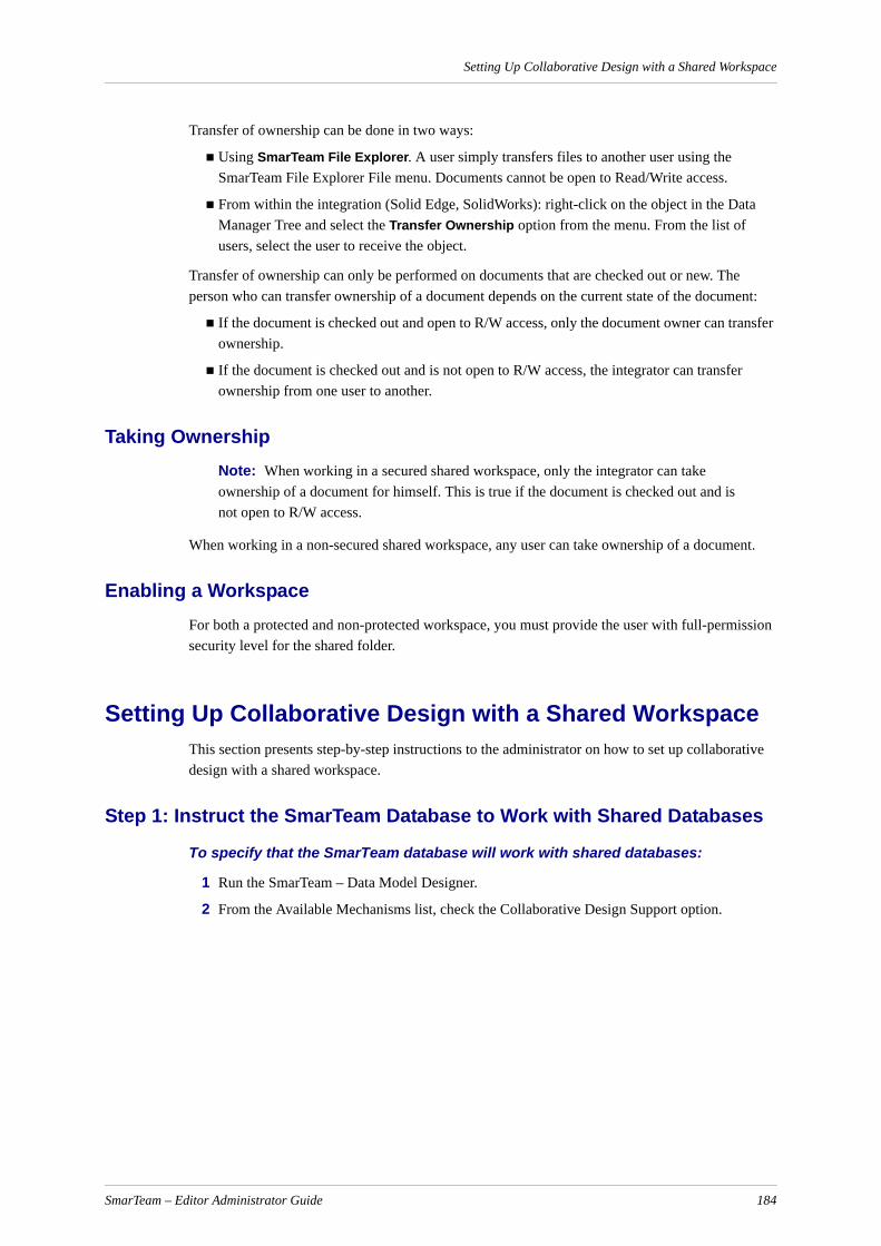
Setting Up Collaborative Design with a Shared Workspace
Transfer of ownership can be done in two ways:
Using SmarTeam File Explorer. A user simply transfers files to another user using the SmarTeam File Explorer File menu. Documents cannot be open to Read/Write access.
From within the integration (Solid Edge, SolidWorks): right-click on the object in the Data Manager Tree and select the Transfer Ownership option from the menu. From the list of users, select the user to receive the object.
Transfer of ownership can only be performed on documents that are checked out or new. The person who can transfer ownership of a document depends on the current state of the document:
If the document is checked out and open to R/W access, only the document owner can transfer ownership.
If the document is checked out and is not open to R/W access, the integrator can transfer ownership from one user to another.
Taking OwnershipNote: When working in a secured shared workspace, only the integrator can take ownership of a document for himself. This is true if the document is checked out and is not open to R/W access.
When working in a non-secured shared workspace, any user can take ownership of a document.
Enabling a WorkspaceFor both a protected and non-protected workspace, you must provide the user with full-permission security level for the shared folder.
Setting Up Collaborative Design with a Shared WorkspaceThis section presents step-by-step instructions to the administrator on how to set up collaborative design with a shared workspace.
Step 1: Instruct the SmarTeam Database to Work with Shared Databases
To specify that the SmarTeam database will work with shared databases:
1 Run the SmarTeam – Data Model Designer.
2 From the Available Mechanisms list, check the Collaborative Design Support option.
SmarTeam – Editor Administrator Guide 184
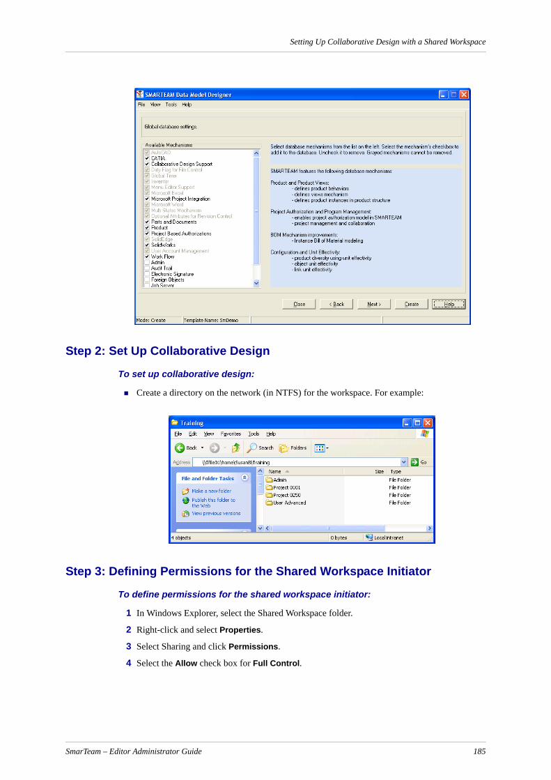
Setting Up Collaborative Design with a Shared Workspace
Step 2: Set Up Collaborative Design
To set up collaborative design:
Create a directory on the network (in NTFS) for the workspace. For example:
Step 3: Defining Permissions for the Shared Workspace Initiator
To define permissions for the shared workspace initiator:
1 In Windows Explorer, select the Shared Workspace folder.
2 Right-click and select Properties.
3 Select Sharing and click Permissions.
4 Select the Allow check box for Full Control.
SmarTeam – Editor Administrator Guide 185
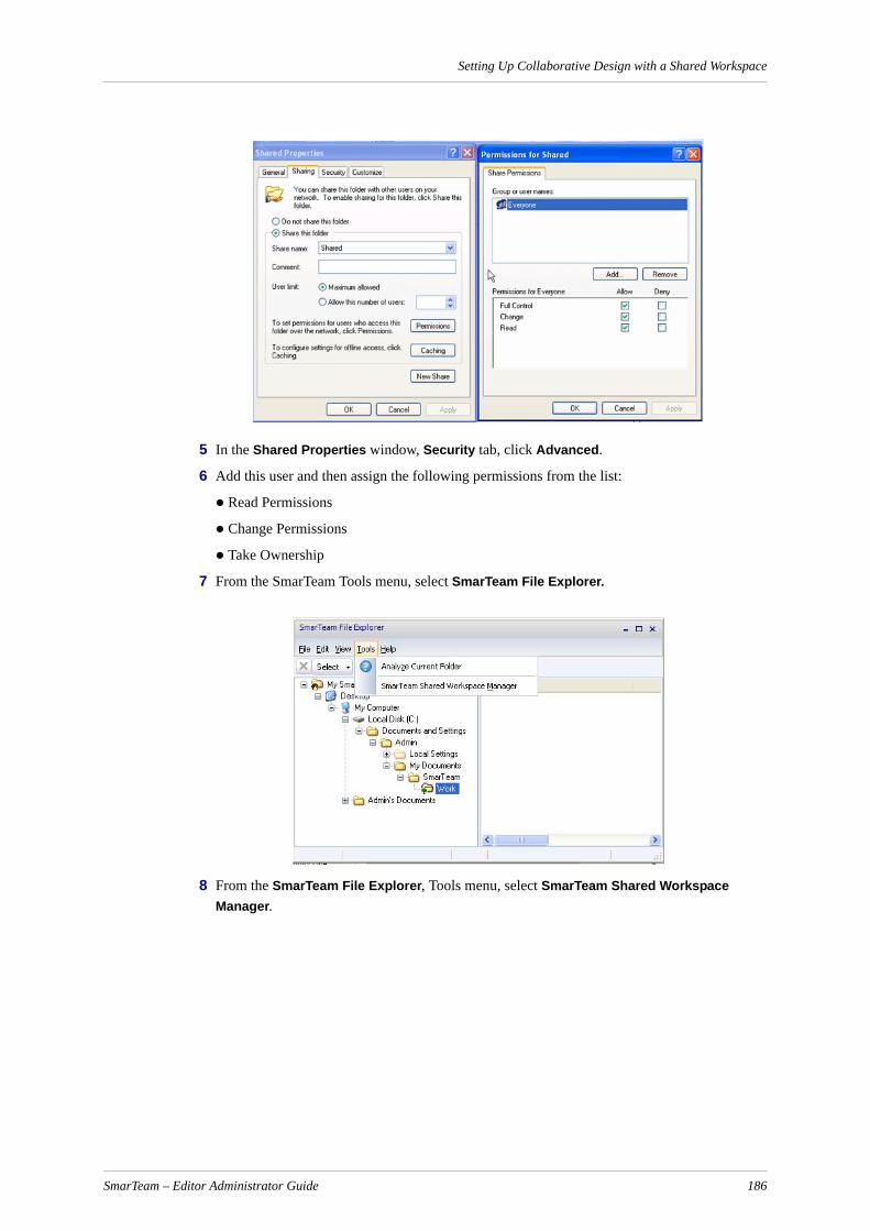
Setting Up Collaborative Design with a Shared Workspace
5 In the Shared Properties window, Security tab, click Advanced.
6 Add this user and then assign the following permissions from the list:
Read Permissions
Change Permissions
Take Ownership
7 From the SmarTeam Tools menu, select SmarTeam File Explorer.
8 From the SmarTeam File Explorer, Tools menu, select SmarTeam Shared Workspace Manager.
SmarTeam – Editor Administrator Guide 186
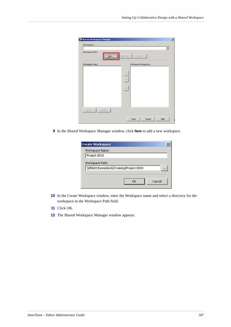
Setting Up Collaborative Design with a Shared Workspace
9 In the Shared Workspace Manager window, click New to add a new workspace.
10 In the Create Workspace window, enter the Workspace name and select a directory for the workspace in the Workspace Path field.
11 Click OK.
12 The Shared Workspace Manager window appears.
SmarTeam – Editor Administrator Guide 187

Setting Up Collaborative Design with a Shared Workspace
The new workspace name is added, and the new user is added to the workspace users list.
13 To add more users, click Add.
The Select Names Window appears.
14 Select the users to be added to the workspace and click OK.
Note: A default integrator is automatically assigned. You can add more than one integrator.
The Shared Workspace Manager window reappears.
15 Select a user from the Workspace Users list and click the right arrow to add it to the Workgroup Integrators list.
16 Click Save.
When you return to the SmarTeam File Explorer, you can see that a new workspace has been created. (If you do not see this, click the refresh button or F5 to refresh the tree.).
SmarTeam – Editor Administrator Guide 188
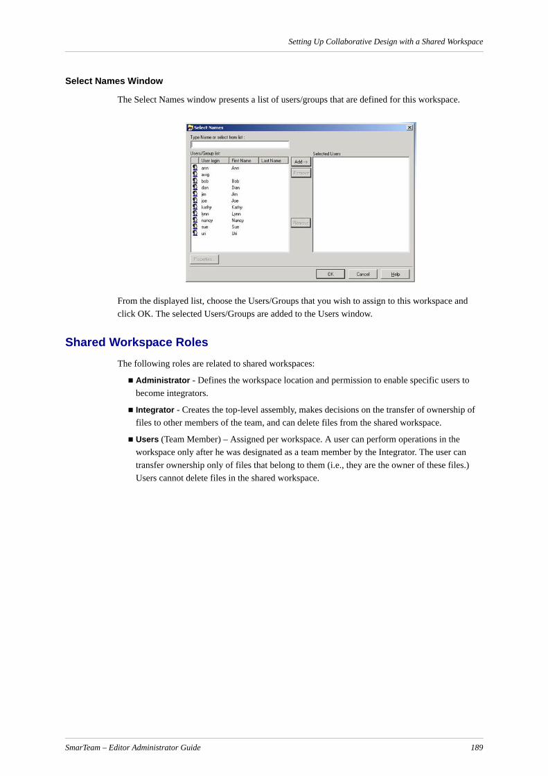
Setting Up Collaborative Design with a Shared Workspace
Select Names Window
The Select Names window presents a list of users/groups that are defined for this workspace.
From the displayed list, choose the Users/Groups that you wish to assign to this workspace and click OK. The selected Users/Groups are added to the Users window.
Shared Workspace RolesThe following roles are related to shared workspaces:
Administrator - Defines the workspace location and permission to enable specific users to become integrators.
Integrator - Creates the top-level assembly, makes decisions on the transfer of ownership of files to other members of the team, and can delete files from the shared workspace.
Users (Team Member) – Assigned per workspace. A user can perform operations in the workspace only after he was designated as a team member by the Integrator. The user can transfer ownership only of files that belong to them (i.e., they are the owner of these files.) Users cannot delete files in the shared workspace.
SmarTeam – Editor Administrator Guide 189

Applications Setup
Applications SetupThe Applications Setup function is generally performed by the system administrator during the setup process. This function enables you to launch external applications in SmarTeam – Editor. This allows you to edit files in the external application in which they were created. This function only needs to be performed the first time when a new external application is added to SmarTeam – Editor.
Defining ApplicationsThe Application Tools window allows you assign application tools to perform standard operations on files of a specified file type. On entry to this window, the available file types as defined in the database are presented.
Adding a New Application Name
To add a new application name to the list:
Note: This process needs to be performed only once.
1 From the SmarTeam – Editor main menu select Tools, Applications Setup to display the Application Tools window. The Application Tools window lists all external applications that have been previously added to SmarTeam – Editor.
2 In the Application Tools window, click Modify to add, delete or change items in the file types list. The File Type window is displayed.
SmarTeam – Editor Administrator Guide 190

Applications Setup
3 In the Value field, enter a new name.
4 Click Add to add the new name to the list of displayed applications.
Note: The path to its executable file has not yet been defined in SmarTeam – Editor.
5 You can select one of the applications and click the Highlight Default button to define this application as the default. When you click in the File Types field in the Profile Card, the selected application is automatically displayed.
If necessary, you can still select another application by updating the Profile Card and in the File Info section selecting a defined application from the dropdown list.
6 Click Close to return to the Application Tools window.
7 You now need to define the path to the external application.
Modifying an Existing Application Name
To modify the name of an existing application:
You can change the name of an external application as it is displayed in the dropdown list of File Types in the Profile Card.
Note: Modifying the name of an application does not change the path to the application's executable file.
1 In the Application Tools window click Modify to open the File Type window.
2 In the File Type window select and highlight the application from the displayed list to display its name in the Value field.
3 In the Value field, enter a new name for the application and click Modify. The new name replaces the old name in the list.
4 Repeat steps 2 and 3 above to modify any other applications.
SmarTeam – Editor Administrator Guide 191
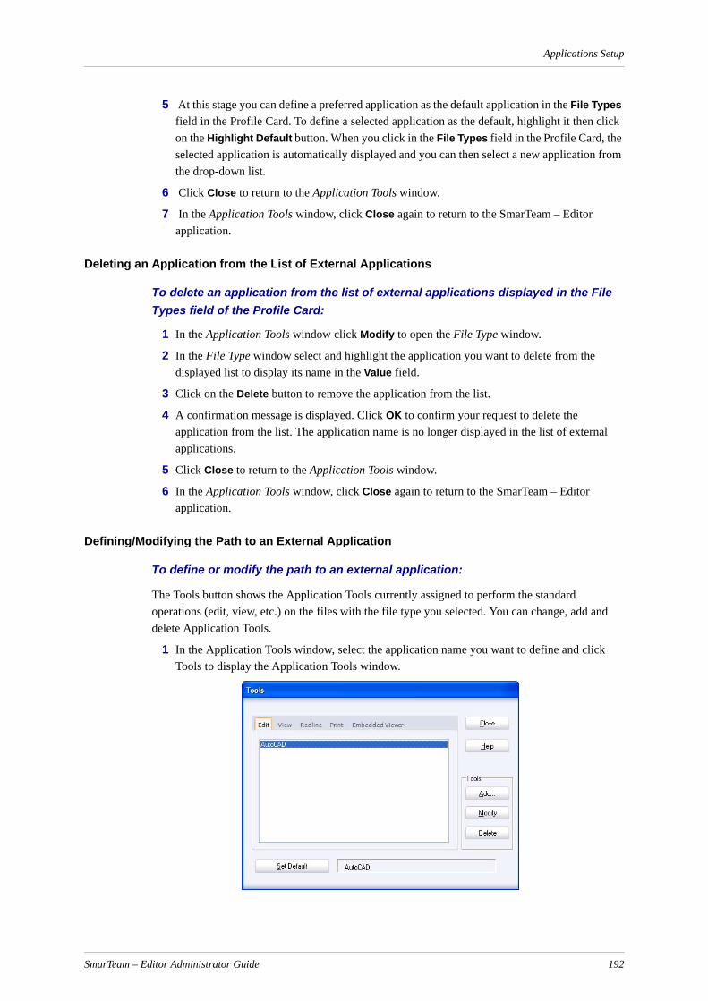
Applications Setup
5 At this stage you can define a preferred application as the default application in the File Types field in the Profile Card. To define a selected application as the default, highlight it then click on the Highlight Default button. When you click in the File Types field in the Profile Card, the selected application is automatically displayed and you can then select a new application from the drop-down list.
6 Click Close to return to the Application Tools window.
7 In the Application Tools window, click Close again to return to the SmarTeam – Editor application.
Deleting an Application from the List of External Applications
To delete an application from the list of external applications displayed in the File Types field of the Profile Card:
1 In the Application Tools window click Modify to open the File Type window.
2 In the File Type window select and highlight the application you want to delete from the displayed list to display its name in the Value field.
3 Click on the Delete button to remove the application from the list.
4 A confirmation message is displayed. Click OK to confirm your request to delete the application from the list. The application name is no longer displayed in the list of external applications.
5 Click Close to return to the Application Tools window.
6 In the Application Tools window, click Close again to return to the SmarTeam – Editor application.
Defining/Modifying the Path to an External Application
To define or modify the path to an external application:
The Tools button shows the Application Tools currently assigned to perform the standard operations (edit, view, etc.) on the files with the file type you selected. You can change, add and delete Application Tools.
1 In the Application Tools window, select the application name you want to define and click Tools to display the Application Tools window.
SmarTeam – Editor Administrator Guide 192
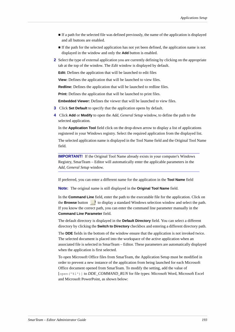
Applications Setup
If a path for the selected file was defined previously, the name of the application is displayed and all buttons are enabled.
If the path for the selected application has not yet been defined, the application name is not displayed in the window and only the Add button is enabled.
2 Select the type of external application you are currently defining by clicking on the appropriate tab at the top of the window. The Edit window is displayed by default.
Edit: Defines the application that will be launched to edit files
View: Defines the application that will be launched to view files.
Redline: Defines the application that will be launched to redline files.
Print: Defines the application that will be launched to print files.
Embedded Viewer: Defines the viewer that will be launched to view files.
3 Click Set Default to specify that the application opens by default.
4 Click Add or Modify to open the Add, General Setup window, to define the path to the selected application.
In the Application Tool field click on the drop-down arrow to display a list of applications registered in your Windows registry. Select the required application from the displayed list.
The selected application name is displayed in the Tool Name field and the Original Tool Name field.
IMPORTANT! If the Original Tool Name already exists in your computer's Windows Registry, SmarTeam – Editor will automatically enter the applicable parameters in the Add, General Setup window.
If preferred, you can enter a different name for the application in the Tool Name field
Note: The original name is still displayed in the Original Tool Name field.
In the Command Line field, enter the path to the executable file for the application. Click on the Browse button to display a standard Windows selection window and select the path. If you know the correct path, you can enter the command line parameter manually in the Command Line Parameter field.
The default directory is displayed in the Default Directory field. You can select a different directory by clicking the Switch to Directory checkbox and entering a different directory path.
The DDE fields in the bottom of the window ensure that the application is not invoked twice. The selected document is placed into the workspace of the active application when an associated file is selected in SmarTeam – Editor. These parameters are automatically displayed when the application is first selected.
To open Microsoft Office files from SmarTeam, the Application Setup must be modified in order to prevent a new instance of the application from being launched for each Microsoft Office document opened from SmarTeam. To modify the setting, add the value of [open("%1")] to DDE_COMMAND_RUN for file types: Microsoft Word, Microsoft Excel and Microsoft PowerPoint, as shown below:
SmarTeam – Editor Administrator Guide 193

Applications Setup
5 Click OK to return to the Tools window. The path of the selected application is now defined in SmarTeam – Editor, and you can launch this application in order to edit a file.
Defining Advanced Parameters
To define advanced parameters:
The Advanced Setup tab enables you to prepare the interface between SmarTeam – Editor and a CAD application. In this window you define which possibilities SmarTeam – Editor can use to view and copy CAD files.
1 In the Application Tools window, select the application name you want to define and click Tools to display the Tools window.
2 Click Add or Modify to define the path to the selected application.
In the displayed window, click the Advanced Setup tab to display the Advanced Setup window.
3 Mark the checkboxes as described below and click OK.
Copy CAD assembly files: Mark this checkbox if you want SmarTeam – Editor to copy all files of an Assembly, sub-Assembly, Items and X-Ref to the working directory.
Note: If a CAD application doesn't require you to copy files of an Assembly, then it is not required to check this field.
SmarTeam – Editor Administrator Guide 194

Applications Setup
4 Search files in current folder: Mark this check box in order to Check Out/Copy files to the default SmarTeam directory. Unmark this check box in order to Check Out/Copy files the original CAD directory
For example: A file was saved in C:\Temp and after Check in, it is placed in vault. Upon Check Out or Copy:
– If this check box is marked, the file is placed in the default SmarTeam user directory C:\Documents and Settings\user\My Documents\SmarTeam\Work.
– If this check box is unmarked, the file is placed in the original CAD directory C:\Temp
Enable CAD search path: Mark this checkbox if you want SmarTeam – Editor to search for a file according to the CAD applications defined search path.
Enable CAD reference change: This field is not implemented in the current version.
CAD Interface DLL: If you check Enable CAD search path, enter the dll file name that interacts between SmarTeam – Editor and the integration. For example, when performing a lifecycle operation in the integration, SmarTeam – Editor will send information to the Title Block drawing.
Disable change of file name: When an object is checked out from the vault, and this option is checked, the object's file name cannot be changed when a Check In operation is performed.
Place current object in the Global Data area: Select this check box to allow all SmarTeam integrations or customer scripts to receive the root object for Out of Vault operations from the SmarTeam SmEngine.GlobalData object. This enables you to deliver object identifiers to the application via the Global Data area. This area is used to send information about an object being edited/viewed by external applications. For example, when an Item is edited, if the object information is not saved inside the Global Data area, the integration will not be able to retrieve the Item file configuration or display it inside the integration's application. The information that is stored in Global data area is a record list containing the following fields: SmRecordList.ValueAsString[NM_FILE_NAME, 0] = FileName
SmRecordList.ValueAsString[NM_DIRECTORY, 0] = Directory
SmRecordList.ValueAsString[NM_APPLICATION_NAME, 0] = ApplicationName SmRecordList.ValueAsObject[NM_OBJECT, 0] = SmObject
The following code example is showing how to access the GlobalData placed object (for Microsoft Word integration). Dim GlobalData As Object, V As Variant, Reclist As ObjectSet GlobalData = SmSession.Engine.GlobalDataSet v = GlobalData.Value("SMTMMICROSOFT WORDOBJECT")If Not IsNull(V) Then Set Reclist = VReclist.PrintToFile "", "" ' Access the RecordList ObjectReclist.ValueAsObject("Object", 0).Data.PrintToFile "", "" 'Access the persistent SmarTeam objectEnd If
File extensions: Enter the file extension(s) for the specified file type. File extension names should be separated by a semi-colon (;).
Enable CFO for lifecycle operations: Enables Common File Objects for the following lifecycle operations: Check Out, Force Check Out and Lock. (Refer to Enabling Common File Objects for further details.)
SmarTeam – Editor Administrator Guide 195
Applications Setup
To delete the executable path to an application:
You can delete the previously defined path to an external application. This process does not delete the name of the application from the displayed list.
1 In the Application Tools window, select the application for the path you want to delete and click Tools. The Application Tools window is displayed.
2 Click the Delete button to delete the previously defined path to the selected application. The application name is still displayed in the Application Tools window, but a path is no longer defined for it.
3 Click Close to save and return to the Application Tools window.
4 In the Application Tools window click Close to return to the SmarTeam – Editor application.
Embedded Viewer Setup
The Embedded Viewer tab page defines a compatible viewer for a particular file type, enabling you to view a selected file from the Profile Card without launching its external application.
Existing file types listed in the Application Tools window are pre-defined for using compatible built-in or plug-in viewers supplied with SmarTeam – Editor. You can modify, delete or add a new viewer to an existing file type. In addition, if you define new file types to the Application Tools window, you can add a compatible viewer for the selected new file type.
IMPORTANT! Whenever you modify an existing viewer for a selected file type, or add a built-in or plug-in viewer to a newly defined file type, you must first contact SmarTeam Technical Support to determine viewer compatibility for the selected file type.
SmarTeam – Editor Administrator Guide 196

Applications Setup
IMPORTANT! When you want to view an assembly in an Embedded Viewer, and the assembly contain sub-assemblies or parts that are needed in order to display the assembly properly, you must first make the following changes in the Application Tools Setup window:1. In the View tab, mark the Copy Cad Assembly Files checkbox. 2. In the Embedded Viewer tab, mark the Copy Cad Assembly Files checkbox.
To modify an existing viewer for a file type:
1 From the SmarTeam – Editor main menu select Tools, Applications Setup to display the Application Tools window. The Application Tools window lists all external applications that have been previously added to SmarTeam – Editor.
2 In the Application Tools window, in the File Type list select and highlight the file name for the viewer you want to modify then click Tools.
The Application Tools window is displayed for the selected file.
3 In the [File Name] – Application Tools window, click on the Embedded Viewer tab page to view the defined viewer for the selected file name.
4 In the [File Name] – Application Tools window click Modify to display the Update window.
Built-in Viewer
To select a built-in viewer, click in the Built-in Viewer radio button. When selected, the Built-in viewer section is enabled. Modify the selected viewer as follows:
Built-in viewers: In the Viewer type field, click on the dropdown arrow to select a viewer type as advised by SmarTeam Technical Support.
Viewer file extension/Redline file extension: These fields are used if a file image is being displayed by a file type other than its own. (For example, certain CAD files are represented by bmp (type) files.) The CAD files are, in fact, being represented by a specific graphic file type. The Redline file extension field is completed automatically, receiving the extension value from the extension format and adding the extension .red to the definition. Therefore, it is only necessary to complete the Viewer file extension field.
SmarTeam – Editor Administrator Guide 197
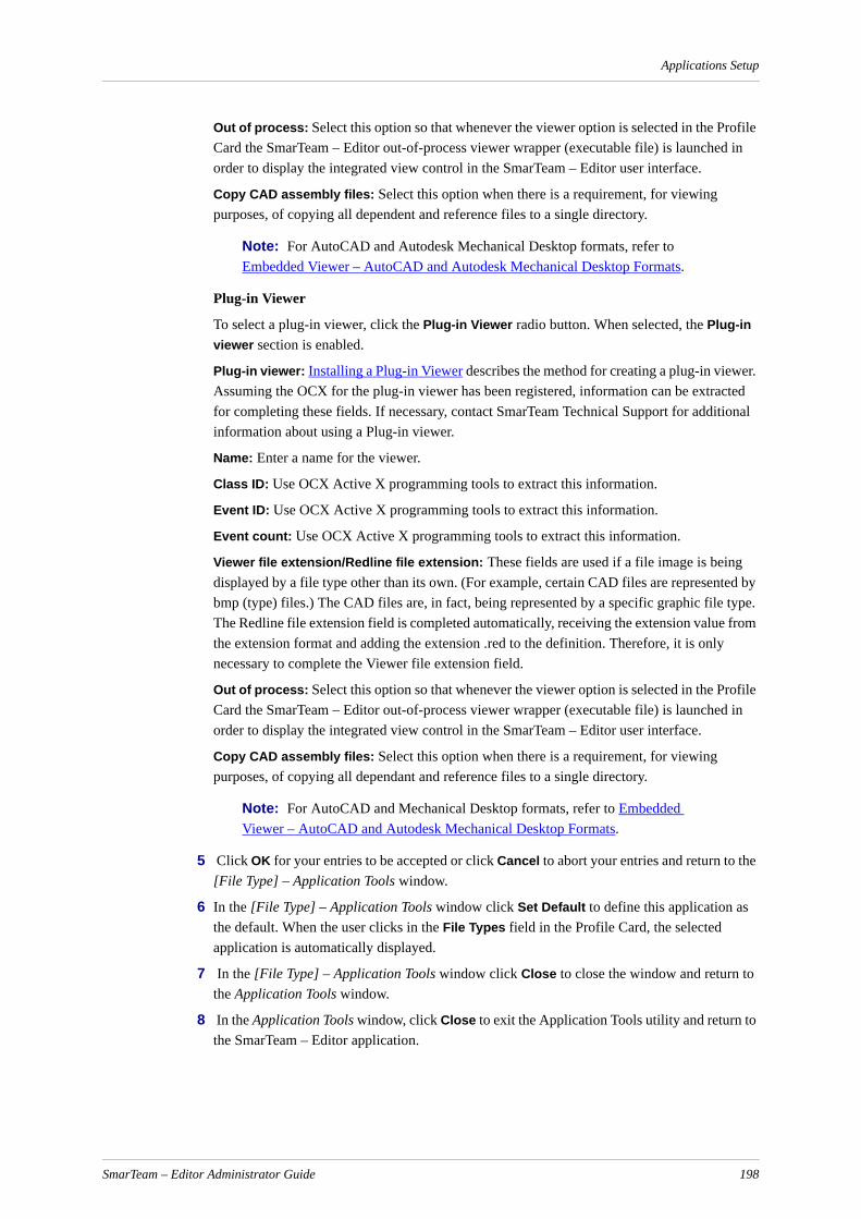
Applications Setup
Out of process: Select this option so that whenever the viewer option is selected in the Profile Card the SmarTeam – Editor out-of-process viewer wrapper (executable file) is launched in order to display the integrated view control in the SmarTeam – Editor user interface.
Copy CAD assembly files: Select this option when there is a requirement, for viewing purposes, of copying all dependent and reference files to a single directory.
Note: For AutoCAD and Autodesk Mechanical Desktop formats, refer to Embedded Viewer – AutoCAD and Autodesk Mechanical Desktop Formats.
Plug-in Viewer
To select a plug-in viewer, click the Plug-in Viewer radio button. When selected, the Plug-in viewer section is enabled.
Plug-in viewer: Installing a Plug-in Viewer describes the method for creating a plug-in viewer. Assuming the OCX for the plug-in viewer has been registered, information can be extracted for completing these fields. If necessary, contact SmarTeam Technical Support for additional information about using a Plug-in viewer.
Name: Enter a name for the viewer.
Class ID: Use OCX Active X programming tools to extract this information.
Event ID: Use OCX Active X programming tools to extract this information.
Event count: Use OCX Active X programming tools to extract this information.
Viewer file extension/Redline file extension: These fields are used if a file image is being displayed by a file type other than its own. (For example, certain CAD files are represented by bmp (type) files.) The CAD files are, in fact, being represented by a specific graphic file type. The Redline file extension field is completed automatically, receiving the extension value from the extension format and adding the extension .red to the definition. Therefore, it is only necessary to complete the Viewer file extension field.
Out of process: Select this option so that whenever the viewer option is selected in the Profile Card the SmarTeam – Editor out-of-process viewer wrapper (executable file) is launched in order to display the integrated view control in the SmarTeam – Editor user interface.
Copy CAD assembly files: Select this option when there is a requirement, for viewing purposes, of copying all dependant and reference files to a single directory.
Note: For AutoCAD and Mechanical Desktop formats, refer to Embedded Viewer – AutoCAD and Autodesk Mechanical Desktop Formats.
5 Click OK for your entries to be accepted or click Cancel to abort your entries and return to the [File Type] – Application Tools window.
6 In the [File Type] – Application Tools window click Set Default to define this application as the default. When the user clicks in the File Types field in the Profile Card, the selected application is automatically displayed.
7 In the [File Type] – Application Tools window click Close to close the window and return to the Application Tools window.
8 In the Application Tools window, click Close to exit the Application Tools utility and return to the SmarTeam – Editor application.
SmarTeam – Editor Administrator Guide 198
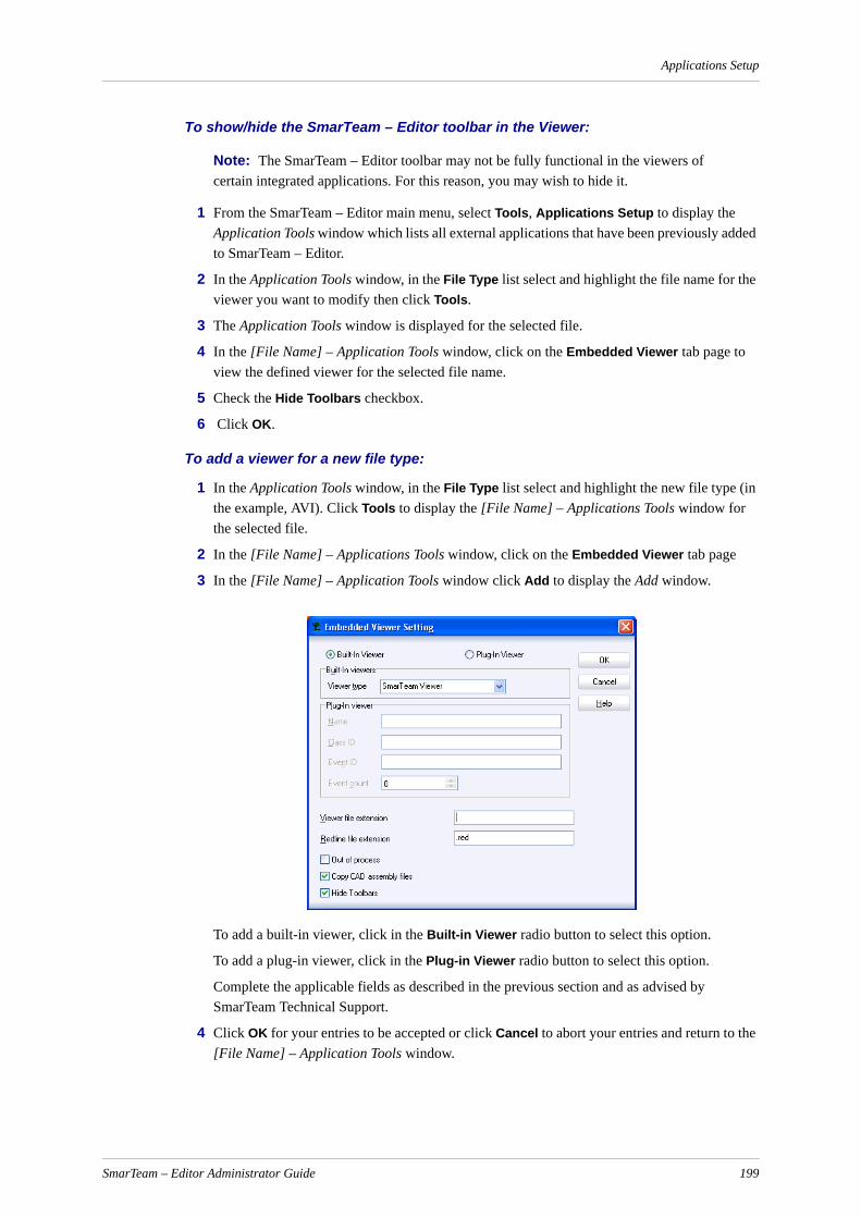
Applications Setup
To show/hide the SmarTeam – Editor toolbar in the Viewer:
Note: The SmarTeam – Editor toolbar may not be fully functional in the viewers of certain integrated applications. For this reason, you may wish to hide it.
1 From the SmarTeam – Editor main menu, select Tools, Applications Setup to display the Application Tools window which lists all external applications that have been previously added to SmarTeam – Editor.
2 In the Application Tools window, in the File Type list select and highlight the file name for the viewer you want to modify then click Tools.
3 The Application Tools window is displayed for the selected file.
4 In the [File Name] – Application Tools window, click on the Embedded Viewer tab page to view the defined viewer for the selected file name.
5 Check the Hide Toolbars checkbox.
6 Click OK.
To add a viewer for a new file type:
1 In the Application Tools window, in the File Type list select and highlight the new file type (in the example, AVI). Click Tools to display the [File Name] – Applications Tools window for the selected file.
2 In the [File Name] – Applications Tools window, click on the Embedded Viewer tab page
3 In the [File Name] – Application Tools window click Add to display the Add window.
To add a built-in viewer, click in the Built-in Viewer radio button to select this option.
To add a plug-in viewer, click in the Plug-in Viewer radio button to select this option.
Complete the applicable fields as described in the previous section and as advised by SmarTeam Technical Support.
4 Click OK for your entries to be accepted or click Cancel to abort your entries and return to the [File Name] – Application Tools window.
SmarTeam – Editor Administrator Guide 199

Applications Setup
The [File Type] – Application Tools window, the newly-defined viewer name appears in the Embedded Viewer tab page for the selected file type.
5 Click Close to close the [File Type] – Application Tools window.
6 In the Application Tools window, click Close to exit the Application Tools utility and return to the SmarTeam – Editor application.
To delete an embedded viewer for a selected file type from the list of external appli-cations displayed in the File Types field of the Profile Card:
1 In the Application Tools window, select and highlight the file name for the viewer you want to delete then click Tools. The [File Name] – Applications Tools window is displayed for the selected file name.
2 In the [File Name] – Applications Tools window, click on the Embedded Viewer tab page to view the defined viewer for the selected file name. Click on the Delete button to remove the defined viewer.
3 A confirmation message is displayed. Click OK to confirm your request to delete the viewer. The viewer name is no longer displayed in the Embedded Viewer tab page.
4 Click Close to return to the Application Tools window.
5 In the Application Tools window, click Close to exit the Application Tools utility and return to the SmarTeam – Editor application.
Embedded Viewer – AutoCAD and Autodesk Mechanical Desktop Formats
When there is a requirement to copy all dependent and reference files to a single directory for AutoCAD and Autodesk Mechanical Desktop formats, it is recom-mended to perform the following:
1 In the Embedded Viewer Add or Update window, as described previously, for Viewer type, select an appropriate viewer. (It is recommended to select DwgViewer, or as advised by Technical Support.)
2 In the Embedded Viewer Add or Update window, check the option Copy CAD assembly files.
3 In the Embedded Viewer Add or Update window, click OK to save your changes, close the window and return to the [File Name] – Application Tools window.
4 In the [File Name] – Application Tools window proceed as follows:
Click on the View tab then click Modify to open the Update window.
In the Update window click on the Advanced Setup tab to view the Advanced Setup page.
In the Advanced Setup page check the options Copy CAD assembly files and Search files in current folder.
Click OK to save your changes and return to the Application Tools window.
5 In the Application Tools window, click Close to exit the Application Tools utility.
6 In the [File Name] – Application Tools window, click Close to save your changes.
7 In the Application Tools window, click Close to exit the Application Tools utility.
SmarTeam – Editor Administrator Guide 200

Applications Setup
Viewing SolidWorks Documents in SmarTeam – Editor Using eDrawingsThe administrator can configure SmarTeam to work with eDrawings as a viewer that can be used to view SolidWorks documents. This viewer enables the user to view and markup files (redlining) using eDrawings tools. When the user moves to another tab or object, they are asked whether on not to save the markup changes.
In the Application Tools Setup, the administrator can specify that eDrawings will be used to view all SolidWorks documents. This applies to eDrawings 2004 and above.
eDrawings supports the following file formats:
To setup viewing SolidWorks documents using eDrawings:
1 In the Application Tools Setup, select an existing viewer and click Modify.
2 The Update window appears.
3 Select Plug-In Viewer.
4 In the Name field, enter the name Smart IE Viewer.
5 In the Class ID and Event ID fields, enter the following code:
156B79D3-C69C-11D4-B595-00104B3E8C2C
6 From the Event count combo box, select 8.
7 In the Redline file extension field, type the extension .All Reviews.markup.
File Type Extension
SolidWorks Part .SLDPRT
SolidWorks Assembly .SLDASM
SolidWorks Drawing .SLDDRW
eDrawings Part .EPRT
eDrawings Assembly .EASM
eDrawings Drawing .EDRW
SmarTeam – Editor Administrator Guide 201

Applications Setup
8 Check the Out of process and Hide Toolbars check boxes.
9 Click OK.
Note: This process must be repeated for each of the following file types:
– SolidWorks Parts
– SolidWorks Assembly
– SolidWorks Drawing
– eDrawings
SmarTeam – Editor Administrator Guide 202
Importing and Exporting
Importing and ExportingThe Import utility enables you to import values for specified attributes in order to create new objects in SmarTeam's database. SmarTeam – Editor enables you to prepare various tasks for Import processes using the Import utility, save them in the database and execute them when needed.
The Export utility enables you to export values from a SmarTeam database in order to transfer them to another database. SmarTeam – Editor facilitates the transfer of data between various systems.
This section contains the following sections:
Import
Export
ImportThe process of importing includes several stages:
Defining an Import
At the first stage, you name the Import and select the Class(es) whose attributes will be assigned values.
Defining the Attributes to Import
At the second stage you can specify values for attributes of a Class. For each attribute you want to import, you can assign an import source that will provide a value.
Attaching a Script
At the third stage, you can modify or filter imported values by attaching a script to an import. This stage is optional.
Importing
After defining attribute values, you can now execute the Import process. During the Import process, objects are created (or updated) in the SmarTeam database with attributes that obtain values from the specified import sources.
Primary IdentifierA primary identifier is one or several attributes that designate a particular object within a Class. This primary identifier must be unique for each object within a SmarTeam Class. As you select attributes to import (and assign values to them), keep in mind that at least one of the attributes that comprise the primary identifier must be assigned a value. Refer to Defining Attributes to Import for operating instructions on defining attributes.
Import SourcesRefer to Import Sources for operating instructions detailing each import source.
SmarTeam – Editor enables you to import values from the following sources:
Database (Table): Values can be loaded from an external database into SmarTeam's structure. For example, you may specify that the values of the State attribute of the imported objects are imported from a specific column in another database.
SmarTeam – Editor Administrator Guide 202
Importing and Exporting
Text File: Values can be loaded from a specific column of a text file into SmarTeam's database. Usually, an external database is transferred into a text file and the text file is then imported into SmarTeam – Editor. The advantage of importing from a text file rather than from a database is that the text file is more portable.
Mask: Values can be generated using a mask. Masks generate values based on a mask formula. For example, if you select Mask as the source of the ID Number attribute, then the value of the ID Number for each imported object will be generated by the selected mask formula.
Fixed Value: Fixed values can be assigned to a selected attribute. For example, you may define that the fixed value, 23/09/99, is assigned to the Creation Date attribute of all imported objects.
Default Value: Default values (based on a SmarTeam – Editor default) can be assigned to a selected attribute. This default value is assigned to the selected attribute of all the imported objects.
Filtering the Import ProcessSmarTeam – Editor enables you to attach a script to an Import process in order to modify or filter the values that are imported.
For example:
Imported values can be modified – by using a script you can replace upper case letters with lower case letters.
Imported values can be filtered – you can limit the number of imported objects by building a filter criterion for adding objects to this Class. Using a script, you can define that all objects whose ID value is above Doc-500 should not be imported, thereby restricting the Import process to 500 objects. Refer to Attaching a Script, for further details.
This section provides the following operating instructions:
Defining an Import, provides instructions for opening the Import utility and defining a new Import process.
Defining the Attributes to Import, provides instructions for selecting attributes and their respective import sources.
Import Sources, provides instructions for importing values from each import source.
Attaching a Script, provides instructions for attaching a script in order to modify or filter the imported values.
Importing Links, provides instructions for importing hierarchical and general link attribute values into SmarTeam – Editor in order to link existing SmarTeam objects.
Defining an Import
Defining an Import is the first step of the Import process. In this step, you define the Import process as follows:
Name the Import.
Define the Class(es) to which Class attributes will be assigned values.
Define the Import mode (Add or Update).
SmarTeam – Editor Administrator Guide 203
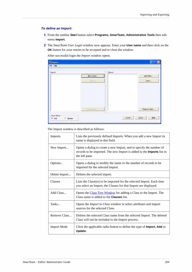
Importing and Exporting
To define an Import:
1 From the taskbar Start button select Programs, SmarTeam, Administrative Tools then sub-menu Import.
2 The SmarTeam User Login window now appears. Enter your User name and then click on the OK button for your entries to be accepted and to close the window.
After successful login the Import window opens.
The Import window is described as follows:
Imports Lists the previously defined Imports. When you add a new Import its name is displayed in this field.
New Import... Opens a dialog to create a new Import, and to specify the number of records to be imported. The new Import is added to the Imports list in the left pane.
Options... Opens a dialog to modify the name or the number of records to be imported for the selected Import.
Delete Import... Deletes the selected import.
Classes Lists the Class(es) to be imported for the selected Import. Each time you select an Import, the Classes for that Import are displayed.
Add Class... Opens the Class Tree Window for adding a Class to the Import. The Class name is added to the Classes list.
Tasks... Opens the Import to Class window to select attributes and import sources for the selected Class.
Remove Class... Deletes the selected Class name from the selected Import. The deleted Class will not be included in the Import process.
Import Mode Click the applicable radio button to define the type of Import, Add or Update.
SmarTeam – Editor Administrator Guide 204
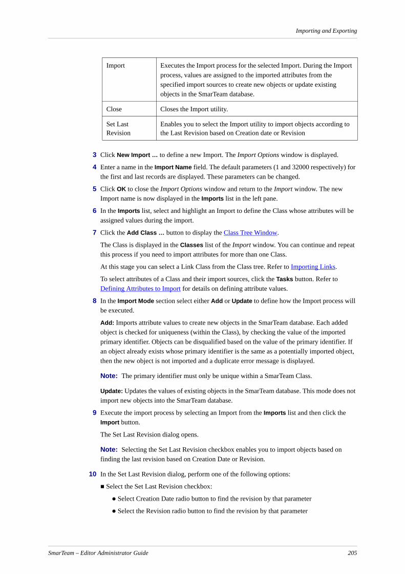
Importing and Exporting
3 Click New Import … to define a new Import. The Import Options window is displayed.
4 Enter a name in the Import Name field. The default parameters (1 and 32000 respectively) for the first and last records are displayed. These parameters can be changed.
5 Click OK to close the Import Options window and return to the Import window. The new Import name is now displayed in the Imports list in the left pane.
6 In the Imports list, select and highlight an Import to define the Class whose attributes will be assigned values during the import.
7 Click the Add Class … button to display the Class Tree Window.
The Class is displayed in the Classes list of the Import window. You can continue and repeat this process if you need to import attributes for more than one Class.
At this stage you can select a Link Class from the Class tree. Refer to Importing Links.
To select attributes of a Class and their import sources, click the Tasks button. Refer to Defining Attributes to Import for details on defining attribute values.
8 In the Import Mode section select either Add or Update to define how the Import process will be executed.
Add: Imports attribute values to create new objects in the SmarTeam database. Each added object is checked for uniqueness (within the Class), by checking the value of the imported primary identifier. Objects can be disqualified based on the value of the primary identifier. If an object already exists whose primary identifier is the same as a potentially imported object, then the new object is not imported and a duplicate error message is displayed.
Note: The primary identifier must only be unique within a SmarTeam Class.
Update: Updates the values of existing objects in the SmarTeam database. This mode does not import new objects into the SmarTeam database.
9 Execute the import process by selecting an Import from the Imports list and then click the Import button.
The Set Last Revision dialog opens.
Note: Selecting the Set Last Revision checkbox enables you to import objects based on finding the last revision based on Creation Date or Revision.
10 In the Set Last Revision dialog, perform one of the following options:
Select the Set Last Revision checkbox:
Select Creation Date radio button to find the revision by that parameter
Select the Revision radio button to find the revision by that parameter
Import Executes the Import process for the selected Import. During the Import process, values are assigned to the imported attributes from the specified import sources to create new objects or update existing objects in the SmarTeam database.
Close Closes the Import utility.
Set Last Revision
Enables you to select the Import utility to import objects according to the Last Revision based on Creation date or Revision
SmarTeam – Editor Administrator Guide 205
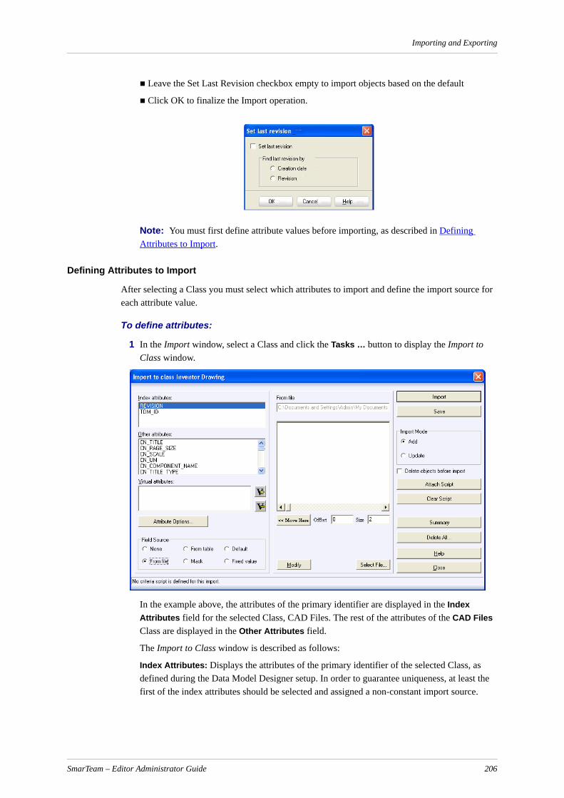
Importing and Exporting
Leave the Set Last Revision checkbox empty to import objects based on the default
Click OK to finalize the Import operation.
Note: You must first define attribute values before importing, as described in Defining Attributes to Import.
Defining Attributes to Import
After selecting a Class you must select which attributes to import and define the import source for each attribute value.
To define attributes:
1 In the Import window, select a Class and click the Tasks … button to display the Import to Class window.
In the example above, the attributes of the primary identifier are displayed in the Index Attributes field for the selected Class, CAD Files. The rest of the attributes of the CAD Files Class are displayed in the Other Attributes field.
The Import to Class window is described as follows:
Index Attributes: Displays the attributes of the primary identifier of the selected Class, as defined during the Data Model Designer setup. In order to guarantee uniqueness, at least the first of the index attributes should be selected and assigned a non-constant import source.
SmarTeam – Editor Administrator Guide 206
Importing and Exporting
Other Attributes: Displays all other attributes of the selected Class, as defined during the Data Model Designer setup. You may select some of these attributes and define import sources for them.
Virtual Attributes: Displays the Virtual Attributes of the import. A Virtual Attribute, described in Attaching a Script and Defining a Virtual Attribute is an additional attribute which can be used as criterion in the attached script for changing attribute values or filtering imported objects. The value for a Virtual Attribute is not actually imported.
IMPORTANT! Lookup Table Attributes: To import Lookup Table attributes, these values should be defined in SmarTeam – Editor before attempting to add the attributes. Values for the Lookup Tables can also be imported. When importing internal Lookup Table values, they should match exactly the values in SmarTeam – Editor – for example Check In and not check in.
IMPORTANT! Reference to Class: These attributes are more complex to import. The SmarTeam Import utility expects OBJECT_ID and not values. For example, when uploading, TDM_USER_ID=1 results in the user being defined as Joe. If the file setting is explicitly set as TDM_USER_ID=Joe, the import process fails.
Attribute Options …: Displays a date format for the Import process. The date format can be modified by clicking the arrow to the right of the Date Format field then choosing a format from the dropdown list. Click OK to return to the Import to Class window.
Field Source: Displays six option buttons for selecting the import source for the selected attribute. Refer to the description in Import Sources.
Import: Executes the Import process.
IMPORTANT! When you click Import in the Import window, the Import process will import values into all the Classes defined for the selected Import. When you click Import in the Import to Class window, the Import process only imports the attributes defined for the Class currently displayed in the window.
Save: Saves the attribute definitions without executing the Import process.
Import Mode: Select and check an option to define the type of Import, Add or Update, as described in Defining an Import.
Delete Objects before Import: When checked, all the objects from the imported class that are in the database will be deleted.
Attach Script: Opens a dialog to attach a script to modify or filter the Import process. You can select a script and function that filters the Import process in the displayed Script Browser window. Refer to Attaching a Script.
Clear Script: Detaches the script.
Summary: Displays a window showing a summary of the assigned attributes and their import sources.
Delete All …: Clears all the previous assignments for attributes and their respective import sources.
Close: Closes the window without saving the definitions.
SmarTeam – Editor Administrator Guide 207

Importing and Exporting
2 Define an import source for the values of a Class attribute, as follows:
Select an attribute from the Index Attributes or Other Attributes fields.
Click on an option button in the Field Source area to define its import source. Each import source and its specific procedure are described in Import Sources.
Repeat this procedure for each attribute you want to import.
3 To attach a script to the Import Class, click Attach Script to display the Script Browser window. In this window, you can select a function that will be attached to the Import process. For example, you can attach a script that changes upper case letters to lower case. Refer to Attaching a Script for further details.
4 To exit the Import from Class window, select one of the following:
Click Save to save the definitions without importing the objects.
Click Close to return to the Import window without saving.
Click Import to execute the Import process.
IMPORTANT! When you click Import, the attribute values of the Class displayed in the displayed Import to Class window are imported into SmarTeam – Editor. If you want to import attribute values of more than one Class, return to the Import window and click Import to import all the Classes displayed in the Classes field, as described in Defining an Import.
Import Sources
The import source must be defined for each attribute you want to import by selecting an option in the Import to Class window, Field Sources area.
The Field Sources options are listed below, with a short explanation. Each option is described in detail in the following pages.
From File The values for the selected attribute are imported from a section (column) of a text file. When the Import takes place, each row in the selected column represents the attribute value for one imported object.
None The selected attribute is not assigned a value.
From File The selected attribute is imported from a section (column) of a text file.
From Table The selected attribute is imported from a column of a database.
Mask The selected attribute is assigned a number automatically, as defined by the mask formula.
Default The selected attribute is assigned the SmarTeam – Editor default value.
Fixed Value The selected attribute is assigned the value entered in the Fixed Value field. All imported objects will have the same fixed value for the selected attribute.
SmarTeam – Editor Administrator Guide 208

Importing and Exporting
During the Import process, the first imported object is assigned the value New for the State attribute, the second imported object is assigned New for the State attribute, and so on. In this way, the sixth object will be assigned the value Released for the State attribute.
To import from a text file:
1 Select an attribute and in the Field Source section click in the From File radio button to select this options. A standard Windows file selection window is displayed.
2 Select a file and click OK to display the text file.
3 Choose the manner in which a column from the text can be selected as follows:
To select Delimited:
In the Import From File window, click Delimited.
Click Next to redisplay the Import From File window.
In the Import From File window, select a delimiter then click OK to return to the Import to Class window. The text file name is displayed in the From file field in the right pane of the Import to Class window.
To select Fixed Width:
In the Import From File window, click Fixed Width.
Click OK to return to the Import to Class window. The text file name is displayed in the From file field in the right pane of the Import to Class window. The text file is also displayed in the right pane.
4 Select the column you want to import by highlighting it.
For a Fixed Width file, you can move the highlighted (blue) area with the mouse or define its position using the Offset and Size fields.
Click Modify to select a different text file or a different delimiter.
Click Select File… to select a different text file.
5 Click Save to save the defined source for the attribute. You can now select another attribute and then define its source.
From TableWhen you select this option, a selected attribute will be imported from a column in a database table.
To import from a table:
1 Select an attribute and in the Field Source section click in the From Table radio button to select this option. The Table Selection window is displayed.
2 In the Databases list, select a database alias to display the list of tables in the Tables list.
3 Select a table as the import source for the attribute and click OK.
4 The selected table is displayed in the center of the Import to Class window. Select the table column that will be the source of the values of the selected attribute. If necessary, click Modify
Delimited To select a column that is defined by a specific delimiter, such as a semi-colon or comma.
Fixed Width To select a column in a fixed format file.
SmarTeam – Editor Administrator Guide 209

Importing and Exporting
to select a different database alias or a different table from the current database alias. The list of database aliases is redisplayed.
5 Click Save to save the defined source for the attribute. You can now select another attribute and then define its source.
MaskWhen you select the Mask in the Field Source section, the imported values for the selected attribute are generated according to a mask formula. The attribute for each subsequent object is assigned a value according to the incrementation rule of the mask formula. You can select a predefined mask or create a new one.
For example: The ID Number attribute is assigned a mask whose formula is DOC 999. When you import objects, the ID Number for the first imported object will be DOC-001, the ID Number for the second imported object will be DOC-002, and so on.
To import using a mask:
1 Select an attribute and in the Field Source section click in the Mask radio button to select this option. The Mask Selection Dialog window is displayed.
2 Select a predefined mask from the Mask List field or create a new mask by clicking the New… button.
Instructions for creating masks are provided in Sequence Designer.
3 In the Mask Selection Dialog window click Select to link the selected mask to the attribute as its source. The Import to Class window is redisplayed with the selected mask.
4 Click the Modify button to redisplay the Mask Selection Dialog window to select a new mask or change the mask formula.
5 Click Save to save the defined mask as the source for the attribute. You can now select another attribute and define its source.
DefaultSelect an attribute and in the Field Source section click in the Default radio button to select this option
The selected attribute is assigned the SmarTeam – Editor default value. For example, if the default value for the State attribute is New, all the imported objects will be assigned the value New for this attribute.
Fixed ValueThe selected attribute is assigned a fixed value. All imported objects will be assigned the same fixed value for this attribute. For example, you may define that the fixed value, 23/02/96, is the value for the Creation Date attribute for all the imported objects.
To import a fixed value:
1 Select an attribute and in the Field Source section click in the Fixed Value radio button to select this option.
A Fixed Value text entry field is displayed in the right pane.
2 Enter text in the field then click Save. This value will be assigned to the selected attribute for all imported objects.
SmarTeam – Editor Administrator Guide 210
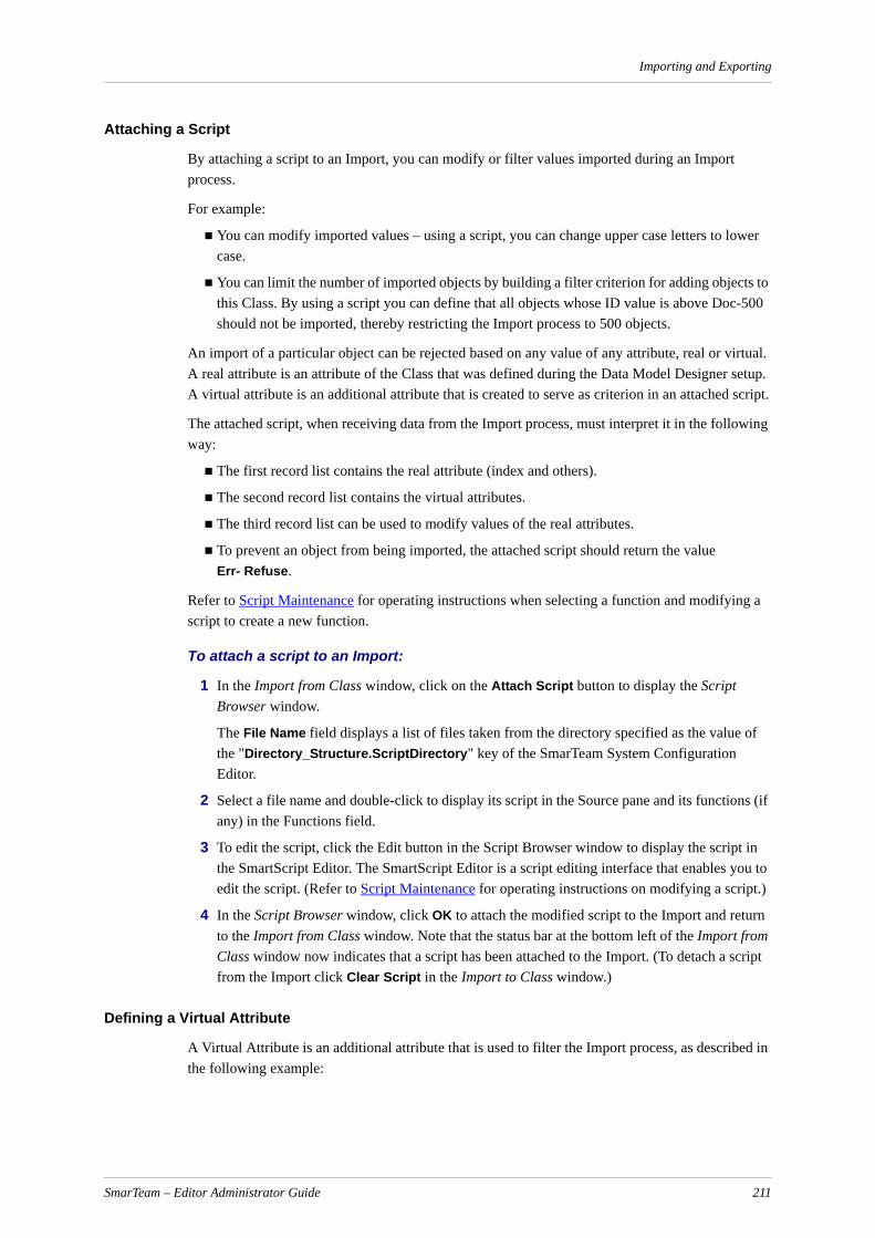
Importing and Exporting
Attaching a Script
By attaching a script to an Import, you can modify or filter values imported during an Import process.
For example:
You can modify imported values – using a script, you can change upper case letters to lower case.
You can limit the number of imported objects by building a filter criterion for adding objects to this Class. By using a script you can define that all objects whose ID value is above Doc-500 should not be imported, thereby restricting the Import process to 500 objects.
An import of a particular object can be rejected based on any value of any attribute, real or virtual. A real attribute is an attribute of the Class that was defined during the Data Model Designer setup. A virtual attribute is an additional attribute that is created to serve as criterion in an attached script.
The attached script, when receiving data from the Import process, must interpret it in the following way:
The first record list contains the real attribute (index and others).
The second record list contains the virtual attributes.
The third record list can be used to modify values of the real attributes.
To prevent an object from being imported, the attached script should return the valueErr- Refuse.
Refer to Script Maintenance for operating instructions when selecting a function and modifying a script to create a new function.
To attach a script to an Import:
1 In the Import from Class window, click on the Attach Script button to display the Script Browser window.
The File Name field displays a list of files taken from the directory specified as the value of the "Directory_Structure.ScriptDirectory" key of the SmarTeam System Configuration Editor.
2 Select a file name and double-click to display its script in the Source pane and its functions (if any) in the Functions field.
3 To edit the script, click the Edit button in the Script Browser window to display the script in the SmartScript Editor. The SmartScript Editor is a script editing interface that enables you to edit the script. (Refer to Script Maintenance for operating instructions on modifying a script.)
4 In the Script Browser window, click OK to attach the modified script to the Import and return to the Import from Class window. Note that the status bar at the bottom left of the Import from Class window now indicates that a script has been attached to the Import. (To detach a script from the Import click Clear Script in the Import to Class window.)
Defining a Virtual Attribute
A Virtual Attribute is an additional attribute that is used to filter the Import process, as described in the following example:
SmarTeam – Editor Administrator Guide 211

Importing and Exporting
In certain circumstances, records of values to be imported need to be filtered by a certain criterion. For example, you may have a text file with lines of values. Each line contains values that relate to one object. The first value in each line may have the value "SKIP" or "ENTER". If the value is "ENTER" the rest of the values in this line should be imported for a new object in the database. If the value is "SKIP", that line should be skipped.In order to perform this task, you may define a virtual attribute named SKIP or ENTER. Specify the source of this attribute, as you would for any ordinary attribute. (In the example above, you would define the source as a text file.) You can then attach a script which will filter the import process, so that only the lines that start with "ENTER" will be entered as objects to the database.
To define a Virtual Attribute:
1 In the Import to Class window, Virtual Attributes section, click to display the Dialog window.
2 In the Dialog window, enter the name of the Virtual Attribute then click OK.
The Virtual Attribute is displayed in the Virtual Attributes pane in the Import from Class window.
Note: To delete a Virtual Attribute, in the Virtual Attributes section highlight the attribute name you want to delete then click .
You can now assign the source for the Virtual Attribute as for any actual class attribute, as described Import Sources.
Importing Links
Since hierarchical and logical links are SmarTeam Classes with their own set of attributes, you can import attribute values for Link Classes in the same manner as other Classes. By importing values for Link attributes, you can create links in the SmarTeam database.
Imported links will define links between objects that already exist in SmarTeam – Editor. When you import the values for link attributes, SmarTeam – Editor searches for the objects according to their primary identifiers and inserts links between them. Therefore, as you define values for Link attributes to import, it is mandatory to specify a value for the primary identifier of the existing objects.
For example:
If you are importing a hierarchical link between the Class Folder and the Class Documents, values for the primary identifier of Folders and Documents must be defined.
If you are importing the logical link called Items Documentation Relation, values for the primary identifiers of Items and Documentation must be defined.
Linking ClassesWhen importing links between Classes that have sub-Classes, it is important to keep in mind that a possibility exists of object duplication. Since the primary identifiers must only be unique within a SmarTeam Class, a situation may arise in which there are two or more objects from several Classes that have an identical value of primary identifiers. For example, you may have a Document whose primary identifier is 037.1 and a Folder whose primary identifier is 037.1.
In the case of hierarchical links, it is possible to avoid duplication by specifying an exact relation (such as Folder < = > Document) rather than selecting Automatic Class Detection.
SmarTeam – Editor Administrator Guide 212

Importing and Exporting
To import a Link Class:
1 In the Import window, click on the Classes button to display the Class Tree Window.
2 In the Class Tree Window, scroll down to locate the Class Link Classes.
Two types of Link Classes are displayed in the window, logical and hierarchical .
3 In the Class Tree Window, select a link then click OK.
When you select a logical link, the link name is displayed in the Classes field of the Import window.
When you select an hierarchical link, the Tree Class Compositions window is displayed in the next step.
4 The Tree Class Compositions window displays possible compositions of the selected Link Class, as defined during the Data Model Designer setup.
5 Select and highlight Automatic Class Detection or a specific relation, as follows:
If you select Automatic Class Detection, SmarTeam – Editor will build all the links for this tree.
If you select a specific relation, SmarTeam – Editor will only build links for two selected Classes. For example, if you specify Component < = > Washer, SmarTeam – Editor will build a link between Components and Washers based on the imported values.
Where a possibility exists of duplicate values for primary identifiers, it is suggested that you select a specific relation as described in Linking Classes.
After making your selection, click OK to save your selection -or click Cancel to abort without saving your selection – to return to the Import window.
6 In the Import window, select the Link Class and click the Tasks button to define the values for the Link attributes. The primary identifiers of each of the Classes to be linked are displayed in the Index Attributes field.
In the above example, the logical link Documents Project Relation was selected. Note that the Index Attributes field displays the primary identifier of both Classes being linked, Documents and Projects.
In the next example, a hierarchical link was selected. Note that the Index Attributes field displays the primary identifiers for the first and second Classes.
7 Define the attributes for each of the primary identifiers:
For a hierarchical link, define the attributes for the first and second Class. The first primary identifier represents the "parent" in the link, and the second primary identifier represents the "child" in the link.
For a logical link, define the attributes for each of the Classes which will be linked logically.
During the Import process, SmarTeam – Editor will find the two objects to be linked (as defined by their primary identifiers) and create a link between them.
8 You can define other link attributes and their respective import sources, as described in Defining Attributes to Import.
9 Click Save to save the defined source for the attribute. If necessary, you can continue and select another attribute for defining its source. (If at this stage you want to abort any changes made without saving, click Close.)
SmarTeam – Editor Administrator Guide 213

Importing and Exporting
10 Click Close to exit the Import to Class window and return to the Import window. Proceed with the Import process as described in Defining an Import.
To import a Lookup Class:
Lookup classes are SmarTeam classes with their own attributes. You can import attribute values for Lookup classes in the same manner as for other classes as described in Linking Classes.
To import values for Lookup Tables:
1 In the Import window, click Add Class… to display the Class Tree Window.
2 In the Class Tree Window, scroll down until you locate the class Lookup Classes.
3 Expand the Lookup Classes tree and select a Lookup Table.
4 Click OK for your selection to be accepted and to close the window. The selected class is displayed in the Import window in the Classes section.
5 In the Import window, Classes section, highlight the selected class then click Tasks.. to open the Import to Class [Lookup Table] window.
6 In the Import to Class [Lookup Table] window, proceed to define the values for the selected Lookup Table as described in Defining Attributes to Import.
ExportSmarTeam – Editor enables you to export values from a SmarTeam database in order to transfer them to another database. As described in the first section, Import, SmarTeam – Editor enables you to import values from an external source, facilitating the transfer of data between systems.
An export file is a file comprised of values that can be imported into a SmarTeam database. The Export utility enables you to create an export file based on a predefined Search. The Search selects SmarTeam objects, according to its search criteria, and the attribute values of these objects are placed in an export file when the Export process is executed. SmarTeam – Editor enables you to define attributes of the Export, such as a record limit and file type (Fixed Width or Delimited). SmarTeam – Editor also enables you to attach a script to modify the values to be exported.
The export process includes the following stages:
Defining an Export
At the first stage, you name the Export and choose the predefined Search that selects the objects for export according to its search criteria. You can also create a new Search, if necessary.
Defining the Properties of the Export
In the second stage, you can specify the properties of the Export process, name an export file and attach a script to modify or filter the values to be exported.
Exporting
After defining values, you can now execute the Export process. During the Export process, an export file is created comprised of the attribute values of the objects selected by the Search.
SmarTeam – Editor Administrator Guide 214
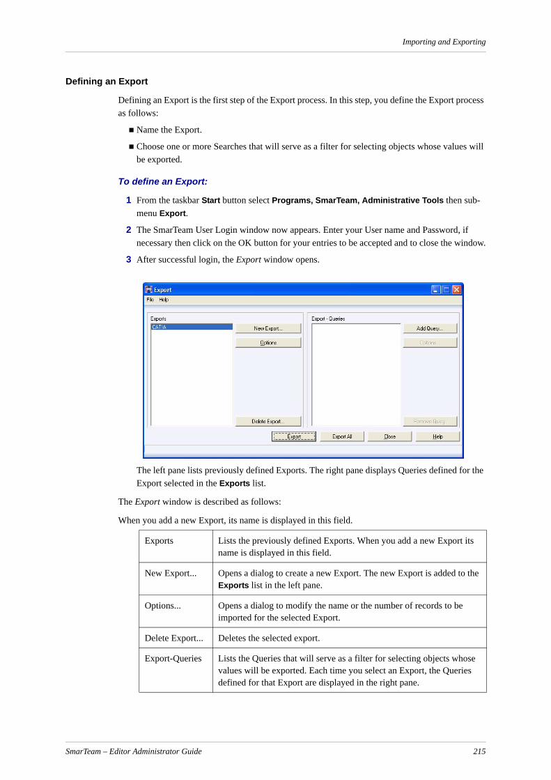
Importing and Exporting
Defining an Export
Defining an Export is the first step of the Export process. In this step, you define the Export process as follows:
Name the Export.
Choose one or more Searches that will serve as a filter for selecting objects whose values will be exported.
To define an Export:
1 From the taskbar Start button select Programs, SmarTeam, Administrative Tools then sub-menu Export.
2 The SmarTeam User Login window now appears. Enter your User name and Password, if necessary then click on the OK button for your entries to be accepted and to close the window.
3 After successful login, the Export window opens.
The left pane lists previously defined Exports. The right pane displays Queries defined for the Export selected in the Exports list.
The Export window is described as follows:
When you add a new Export, its name is displayed in this field.
Exports Lists the previously defined Exports. When you add a new Export its name is displayed in this field.
New Export... Opens a dialog to create a new Export. The new Export is added to the Exports list in the left pane.
Options... Opens a dialog to modify the name or the number of records to be imported for the selected Export.
Delete Export... Deletes the selected export.
Export-Queries Lists the Queries that will serve as a filter for selecting objects whose values will be exported. Each time you select an Export, the Queries defined for that Export are displayed in the right pane.
SmarTeam – Editor Administrator Guide 215

Importing and Exporting
4 Click New Export to define a new Export. The Export Options window is displayed.
5 Enter a name in the Export Name field and a description in the Export Description field (optional).
6 Click OK to close the Export Options window and return to the Export window. The new Export name is now displayed in the Exports list in the left pane.
7 To select a Query by which objects are selected for export, select an export from the Exports list then click Add Query …. The Search Editor window is displayed.
The Search Editor window enables you to carry out the following search actions:
Select a predefined Query, as described in the next step.
OR
Click Add to create a new Query. After creating a new Query, you can then proceed to the next step and select it from the Search Editor window.
OR
Click Modify to modify a selected Query. After modifying an existing search, you can then proceed to the next step and select it from the Search Editor window.
Refer to Creating and Modifying Searches, for complete instructions on using the Search Editor window.
8 In the Search Editor window, select a Query then click Select. The Query is displayed in the Export queries list in the Export window.
9 Define the Export properties, as described in Defining an Export.
10 Click on the Export button to execute the Export process. Refer to Export.
Defining Export Properties
Define Export properties for the Export process as follows:
Name the export file.
Specify the maximum number of records to be exported.
Specify a file type (Fixed Width or Delimited)
Add Query... Opens a dialog to add a Query to the Export. The Query name is added to the Export queries list in the right pane.
Options... Opens the Export Query Attributes window for defining the properties of the Export, naming the Export file and attaching a script to modify or filter the values to be exported.
Remove Query...
Removes the selected Query from the Export. The deleted Query will no longer be included in the Export process.
Export Executes the Export process for the selected Search.
Export All Executes the Export process for all the Queries displayed in the Export queries field.
Close Closes the Export utility.
SmarTeam – Editor Administrator Guide 216
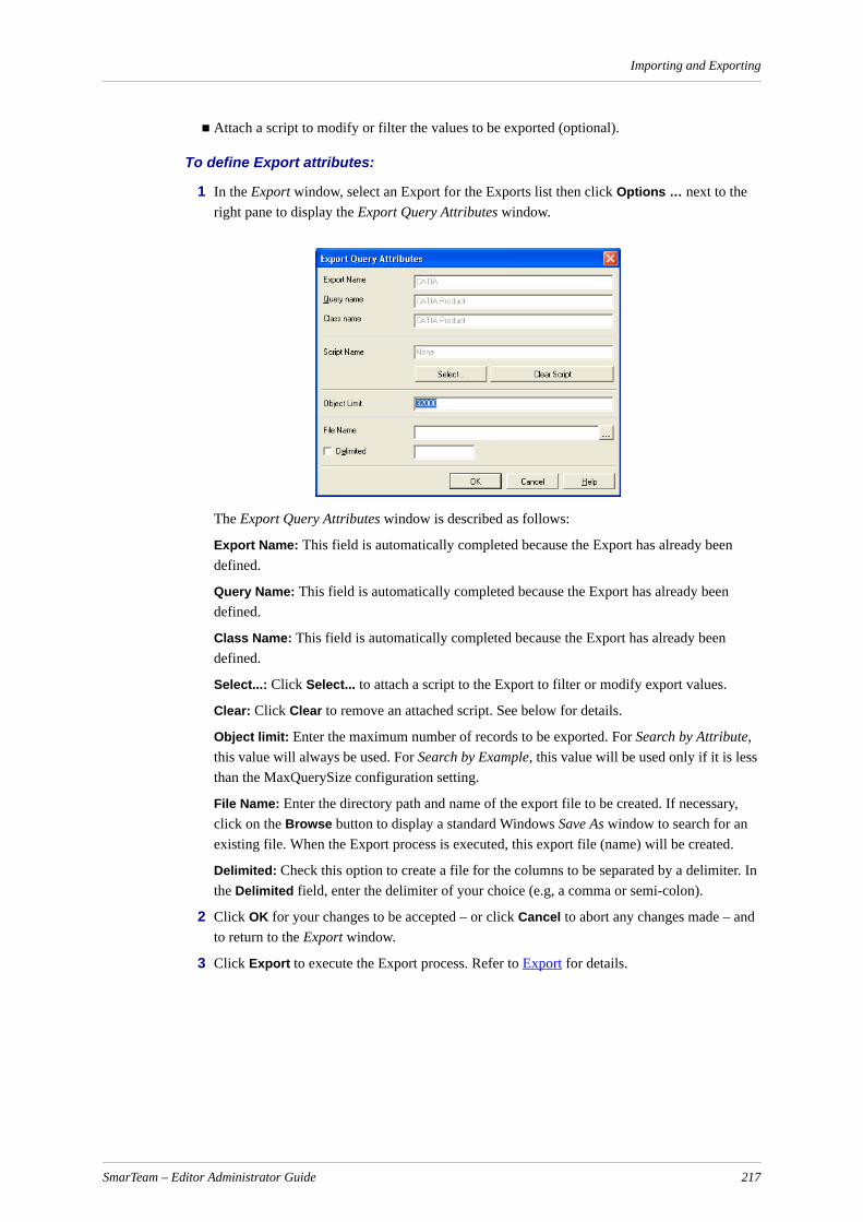
Importing and Exporting
Attach a script to modify or filter the values to be exported (optional).
To define Export attributes:
1 In the Export window, select an Export for the Exports list then click Options … next to the right pane to display the Export Query Attributes window.
The Export Query Attributes window is described as follows:
Export Name: This field is automatically completed because the Export has already been defined.
Query Name: This field is automatically completed because the Export has already been defined.
Class Name: This field is automatically completed because the Export has already been defined.
Select...: Click Select... to attach a script to the Export to filter or modify export values.
Clear: Click Clear to remove an attached script. See below for details.
Object limit: Enter the maximum number of records to be exported. For Search by Attribute, this value will always be used. For Search by Example, this value will be used only if it is less than the MaxQuerySize configuration setting.
File Name: Enter the directory path and name of the export file to be created. If necessary, click on the Browse button to display a standard Windows Save As window to search for an existing file. When the Export process is executed, this export file (name) will be created.
Delimited: Check this option to create a file for the columns to be separated by a delimiter. In the Delimited field, enter the delimiter of your choice (e.g, a comma or semi-colon).
2 Click OK for your changes to be accepted – or click Cancel to abort any changes made – and to return to the Export window.
3 Click Export to execute the Export process. Refer to Export for details.
SmarTeam – Editor Administrator Guide 217
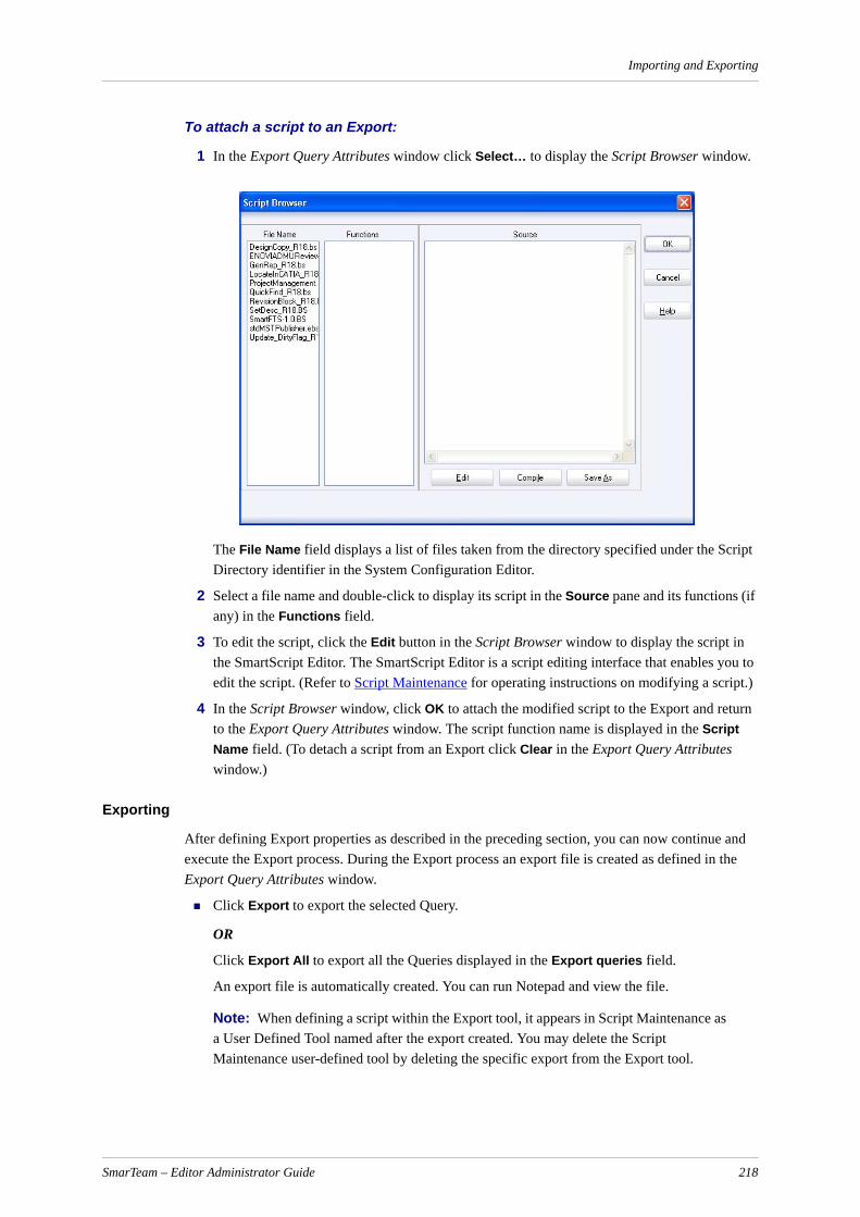
Importing and Exporting
To attach a script to an Export:
1 In the Export Query Attributes window click Select… to display the Script Browser window.
The File Name field displays a list of files taken from the directory specified under the Script Directory identifier in the System Configuration Editor.
2 Select a file name and double-click to display its script in the Source pane and its functions (if any) in the Functions field.
3 To edit the script, click the Edit button in the Script Browser window to display the script in the SmartScript Editor. The SmartScript Editor is a script editing interface that enables you to edit the script. (Refer to Script Maintenance for operating instructions on modifying a script.)
4 In the Script Browser window, click OK to attach the modified script to the Export and return to the Export Query Attributes window. The script function name is displayed in the Script Name field. (To detach a script from an Export click Clear in the Export Query Attributes window.)
Exporting
After defining Export properties as described in the preceding section, you can now continue and execute the Export process. During the Export process an export file is created as defined in the Export Query Attributes window.
Click Export to export the selected Query.
OR
Click Export All to export all the Queries displayed in the Export queries field.
An export file is automatically created. You can run Notepad and view the file.
Note: When defining a script within the Export tool, it appears in Script Maintenance as a User Defined Tool named after the export created. You may delete the Script Maintenance user-defined tool by deleting the specific export from the Export tool.
SmarTeam – Editor Administrator Guide 218

Installing a Plug-in Viewer
Installing a Plug-in ViewerThis section provides a guideline of how to implement OCX ActiveX technology in order to inte-grate Plug-In viewers into your SmarTeam – Editor application.
OCX ActiveX is a Windows technology, which allows the programmer to easily integrate, or "plug-in" applications while providing mechanisms and controls for operating the application's functionality. For example, after plugging-in a viewer, controls will be provided to manipulate the image.
SmarTeam – Editor enables use of Plug-In viewers within the application via the Application Tools utility, accessed from the SmarTeam – Editor main menu.
Integrating Plug-In viewers by certified solution providers is possible according to the following guidelines:
The VAR/Solution provider will be responsible for integrating the Plug-In viewer and providing support and maintenance to the customers that use his solution.
SmarTeam Corporation is not responsible for the viewer once a Plug-In viewer is being used.
SmarTeam Out-Of-The-Box viewer capabilities are included in the purchased product and introduction of substituting viewers will not result in price reduction or discount.
SmarTeam Corporation recommends employing this OCX wrapping solution only when abso-lutely necessary (on large accounts or specific formats). SmarTeam Corporation is free to change its policy regarding this issue in the future and will inform the appropriate partners accordingly.
Preliminary RequirementsIn order to integrate Plug-in viewers within SmarTeam – Editor there are two prerequisites to take into consideration:
An appropriate viewer control should be prepared (ActiveX-OCX)
The option Out-of-process viewing should be enabled for SmarTeam – Editor.
Plug-in Viewer DefinitionsIn order to integrate a Plug-in viewer, an ActiveX should first be prepared in order to display the images.
The ActiveX (OCX control) should support the following properties and methods with the appropriate indexes.
Properties
Index Property Type
1 DrawingName String
2 ShowRedLining Boolean
3 RedLine Tools Integer
SmarTeam – Editor Administrator Guide 219
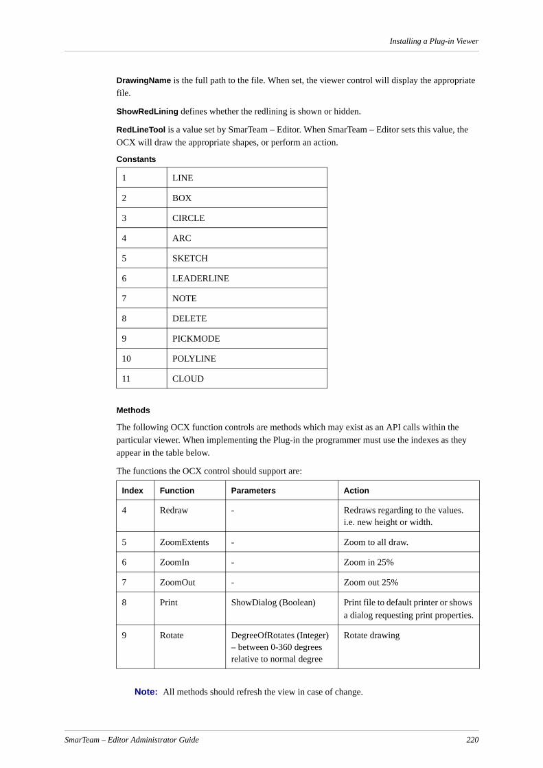
Installing a Plug-in Viewer
DrawingName is the full path to the file. When set, the viewer control will display the appropriate file.
ShowRedLining defines whether the redlining is shown or hidden.
RedLineTool is a value set by SmarTeam – Editor. When SmarTeam – Editor sets this value, the OCX will draw the appropriate shapes, or perform an action.
Constants
Methods
The following OCX function controls are methods which may exist as an API calls within the particular viewer. When implementing the Plug-in the programmer must use the indexes as they appear in the table below.
The functions the OCX control should support are:
Note: All methods should refresh the view in case of change.
1 LINE
2 BOX
3 CIRCLE
4 ARC
5 SKETCH
6 LEADERLINE
7 NOTE
8 DELETE
9 PICKMODE
10 POLYLINE
11 CLOUD
Index Function Parameters Action
4 Redraw - Redraws regarding to the values. i.e. new height or width.
5 ZoomExtents - Zoom to all draw.
6 ZoomIn - Zoom in 25%
7 ZoomOut - Zoom out 25%
8 Print ShowDialog (Boolean) Print file to default printer or shows a dialog requesting print properties.
9 Rotate DegreeOfRotates (Integer) – between 0-360 degrees relative to normal degree
Rotate drawing
SmarTeam – Editor Administrator Guide 220

Installing a Plug-in Viewer
Return values (Integer): success should be identified by a positive (>0) value
Out Of Process
Out-of-process means that whenever the viewer tab is selected, a SmarTeam – Editor out-of-process viewer wrapper (executable) is launched in order to display the integrated viewer control in the SmarTeam – Editor user interface.
To enable Out-of-process:
Each viewer has an ID number. By adding or removing the # on the UseOutofProcess =YES identifier, the out of process will be activated.
For example:
[ReplaceNamefor Plug-In viewer (unique name)]
ID=5
UseOutProcessViewer=YES
Adding a Plug-in viewer can be accomplished using either of the following two SmarTeam support methods:
System Configuration Service
Application Tools Utility
Adding a Plug-in Viewer using the Application Tools UtilityRefer to Embedded Viewer Setup for further details about the Application Tools utility.
Add the required file type to the Application Tools then exit the utility.
1 In the Application Tools window click Tools to open the [File Name] – Application Tools window.
2 Click on the Embedded Viewer tab then click Add.to open the Add window.
3 Click in the Plug-in Viewer radio button. When selected, the Plug-in Viewer section is enabled.
4 Fill in the fields as follows:
SmarTeam – Editor Administrator Guide 221

Installing a Plug-in Viewer
Name - Enter a name for your viewer.
Class ID - Enter the following value: 4B31D7EC-173C-11D2-A552-0020AFE847F0
Event ID - Enter the following value: 4B31D7EB-173C-11D2-A552-0020AFE847F0
Event Count - Enter 8.
5 Check the Out of Process check box depending on the system and application parameters.
6 Click OK to save your changes and close the window.
7 Exit the Application Tools utility.
8 Ensure that you have registered the OCX using the regsvr32 utility.
For example:
regsvr32 "D:\My Documents\viewer\SolidEdge\SEpartX.ocx"
The new viewer can now be used with the chosen format.
SmarTeam – Editor Administrator Guide 222
Design Copy
Design Copy
Design Copy Tool SetupThe Design Copy tool allows SmarTeam – Editor users to create a new SmarTeam object structure by copying selected objects from an existing assembly, duplicating selected objects, their files and links.
To enable this tool to function, the SmarTeam System Administrator must perform the following:
Using the Script Maintenance utility, select the script file DesignCopy.bs to add a new user defined tool named Design Copy.
If applicable, use the Menu Editor utility to add a new menu item, Design Copy, to existing menu profiles.
In order to specify which objects are to participate in the Design Copy, define Check Out rules in the Lifecycle Rules Setup window for each link behavior to be included in the Design Copy. For details of how to define rules in the Lifecycle Rules Setup, see Lifecycle Rules Setup. Behaviors for which Check Out rules have not been defined will not be included in the Design Copy.
For CAD links, Check Out rules can be defined in Normal and/or Reverse directions. In these cases, only the objects that are connected in the direction defined will be included in the Design Copy. For example, if a Check Out rule is defined in the Normal direction, objects that are in the Reverse direction will not be included in the Design Copy.
To install the Before Design Copy script, press Assign. The script dialog box opens, allowing you to select a script, e.g., DesignCopyInit.bs.
Notes:
a Design Copy only displays reverse links of objects related to the objects in the tree built by Design Copy if the objects are linked to the tree by hierarchy. For example, if there are two items inserted into the drawing, and the user performs a Design Copy of one item, only this item and drawing will be copied. The second item will not be copied.
b When performing a Design Copy operation, a new object is created and all attributes are copied from the original object except for revision attributes, which are initialized.
c When components are duplicated using Design Copy, markups of the original components are duplicated and attached to the new components.
d After running Design Copy, it is not possible to cancel the Design Copy process. When you click Cancel on a profile card, the display of the following profile cards is canceled, but the Design Copy operation continues.
Design Copy Administrator Options WindowThe Design Copy Adminstrator Options window allows the administrator to enable the Design Copy feature for specific users. You must have Administrator privileges to access this window. Using this dialog, you can assign the Before Design Copy script and update the Exclude classes list.
To access the Design Copy Adminstrator Options window:
1 Select the Administrator Options.... button from the Design Copy Options Window.
SmarTeam – Editor Administrator Guide 223
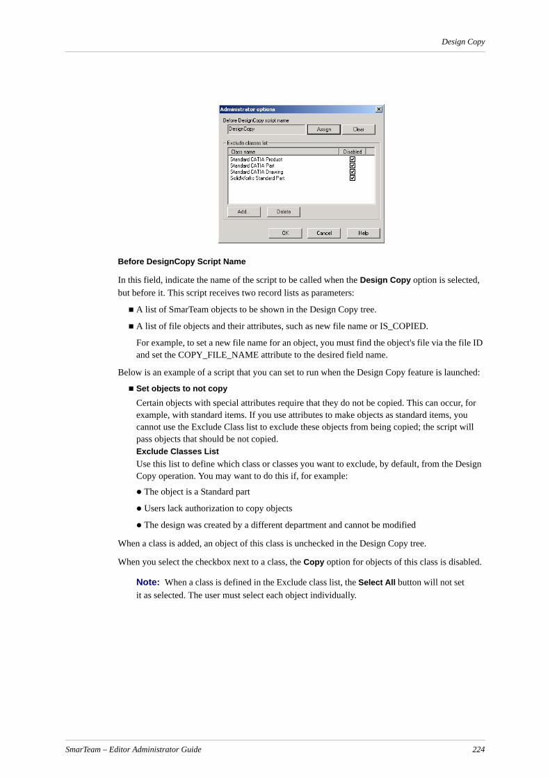
Design Copy
Before DesignCopy Script Name
In this field, indicate the name of the script to be called when the Design Copy option is selected, but before it. This script receives two record lists as parameters:
A list of SmarTeam objects to be shown in the Design Copy tree.
A list of file objects and their attributes, such as new file name or IS_COPIED.
For example, to set a new file name for an object, you must find the object's file via the file ID and set the COPY_FILE_NAME attribute to the desired field name.
Below is an example of a script that you can set to run when the Design Copy feature is launched:
Set objects to not copy
Certain objects with special attributes require that they do not be copied. This can occur, for example, with standard items. If you use attributes to make objects as standard items, you cannot use the Exclude Class list to exclude these objects from being copied; the script will pass objects that should be not copied.Exclude Classes ListUse this list to define which class or classes you want to exclude, by default, from the Design Copy operation. You may want to do this if, for example:
The object is a Standard part
Users lack authorization to copy objects
The design was created by a different department and cannot be modified
When a class is added, an object of this class is unchecked in the Design Copy tree.
When you select the checkbox next to a class, the Copy option for objects of this class is disabled.
Note: When a class is defined in the Exclude class list, the Select All button will not set it as selected. The user must select each object individually.
SmarTeam – Editor Administrator Guide 224

Design Copy
Disabled objects are shown in gray. This feature is useful for the copying of assemblies with standard items.
Setting Partial Copy in Design CopyNew objects created in Design Copy can be secured according to a defined project. The authorizations for the objects will be determined according to the project-based authorizations.
If the design contains objects that the user is not allowed to view or is not allowed to copy the object’s files, a warning message is displayed.
Note: Out-of-vault files are not checked for copy permissions.
The warning message displayed depends on the value of the key DesignCopy.AllowPartialCopy. If the key is set to NO, the following message is displayed:
The design <object ID> contains unauthorized objects. You are not authorized to perform the Design Copy for this design.
If the key is set to YES, the following message is displayed:
The design <object ID> contains unauthorized objects. Continuing with this operation may have incomplete results. In this case, complete the operation in the CAD system. Continue? Yes/No
If the user selects Yes, the Design Copy window appears with the authorized objects tree, and the user can create a new design. The new design does not include objects that are unauthorized to this user.
Note: When opening a new design in a CAD system, the system searches for all non-authorized files, and the user can fix these files manually.
Add Click Add to select and add classes to the list of files to be excluded.Note: If you add a class that is not a leaf class, the class’s children will inherit the parent’s behaviors.
Delete Highlight the classes you want to exclude and click Delete to remove them from the list.
OK Click OK to save changed options.
Cancel Click Cancel to abort any option changes made.
SmarTeam – Editor Administrator Guide 225
National Language Support
National Language SupportThis chapter contains two sections:
Translation Utility - Provides capabilities to add and modify translations of text entities into different languages.
Multilanguage Enabler - Describes how to extract translatable data of the SmarTeam user interface. This is required only if you upgrade from R11 and below
Note: National Language Support (NLS) does not support Flowchart Nodes and Actions.They are freely written texts, and have no support in the Flow Chart Designer for NLS.
Translation UtilitySmarTeam’s Translation Utility provides translations of the following text entities into languages other than English:
Visual controls
Profile cards
Error messages
Specific/unique database-related items
Profile cards
Metadata
User data
System data
Visual controls and error messages are common for all SmarTeam databases, and come translated by default into French, German and Japanese. The other items are database-dependent and you need to translate them separately using the Translation Utility. You can also add custom error messages, which are stored in the custom folder.
Note: The standard PLMDB database included in the SmarTeam installation comes in English with translations to each of the default languages. Items that have been entered into any of your organization’s databases need to be translated separately. You migrate them for translation using the NLS Multilanguage Enabler. For details, see Multilanguage Enabler.
All new translations stored and accessed by the Translation Utility become independent of any SmarTeam databases.
Note: In the System Configuration Service, the NLS root path configuration key is located under Miscellaneous Configuration / National Languages Support / Root Path.
SmarTeam – Editor Administrator Guide 226
National Language Support
Selecting a Language in SmarTeam
SmarTeam – Editor users can change the displayed language for all windows in the interface by selecting a language from the SmarTeam – Editor main menu, Tools, Language Selection submenu.
Translation Utility User Interface
SmarTeam – Editor users can change the displayed language for all windows in the interface by selecting a language from the SmarTeam – Editor main menu, Tools, Language Selection submenu.
The main menu contains the following options:
File
Exit (Alt+F4)
Edit
Cut (Ctrl+X)
Copy (Ctrl+C)
Paste (Ctrl+V)
Find and Replace
Word Count
View
Select Source Languages
Tools
Add Language
SmarTeam – Editor Administrator Guide 227

National Language Support
Below the menu are the Find and Replace icons and the Current Language combo box.
The main screen is divided into two panes.
The left pane shows the detailed branches of translatable items, such as visual controls, profile cards, error messages, etc. At the bottom, there are Expand All and Collapse All buttons, which serve to expand and collapse the views of the tree’s branches.
The right pane shows the localization tables. You can customize the view to display any number of languages with their respective translated counterparts on an item by item basis.
See Also
Showing Existing Localizations
Finding and Replacing Localized Items
Translation Utility Tasks
It is recommended that you migrate legacy translations from SmarTeam versions prior to V5R12 to the Translation Utility. Refer to the Procedure for Migrating to SmarTeam V5R1x document located on the documentation CD.
You can perform the following tasks using the NLS system.
Showing Existing Localizations
Finding and Replacing Localized Items
Setting the Translation Utility Root Path
Showing Existing LocalizationsYou can see existing translations presented together in chart form. This can aid you in adding versions or languages or making changes that your organization deems necessary.
To show existing localizations:
1 In the Translation Utility main screen, select the localization you wish to view from the Current Language combo box.
2 From the Translation Utility main menu, select View, Select Source Languages.
The Select Language dialog appears.
3 Using the checkboxes, select the languages you wish to view alongside your chosen Current Language, and click OK.
The complete matrix of languages and corresponding translations for each item is displayed in the right pane.
4 To browse through the various translation categories, click the desired branch in the left pane. To facilitate navigation, use the Expand All and Collapse All buttons located just below the left pane.
Adding Languages in the Translation UtilityYou can add another language to the Translation Utility at any time.
To add a language:
1 From the Translation Utility main menu, select Tools, Add language.
The Add Language dialog appears.
SmarTeam – Editor Administrator Guide 228
National Language Support
2 From the combo box, select your language of choice.
3 Click OK.
The language is added.
Finding and Replacing Localized ItemsWhen searching for a single word or phrase, instead of browsing, it can be more efficient to use the Find function. Likewise, the Replace function allows you to replace one, several or all instances of a given translation.
To find a localized item:
1 From the Translation Utility main menu, select Find and Replace.
OR
Click the Find icon .
2 Enter the text to search for in the Text to Find field.
3 To search only in the current node in the left pane, in the Scope group box, select the Current Table radio button.
4 To search all tables, select the All Tables radio button.
5 To search the tables of the children of the current node, select the Include Child Tables check box.
6 To find only the exact text that you have entered, in the Options group box, select the Whole Field Only checkbox. Otherwise, when this checkbox is blank, the search engine will find any occurrence of your text.
7 Click OK.
8 If there are additional occurrences of your text selection, click OK again to find each one in sequence. When you have finished searching, click Close.
To replace a localized item:
1 From the Translation Utility main menu, select Find and Replace.
OR
Click the Find and Replace icon .
2 Enter the text to search for in the Text to Find field.
3 To search only in the current node in the left pane, in the Scope group box, select the Current Table radio button. To search all tables, select the All Tables radio button.
4 To find only the exact text that you have entered, in the Options group box, select the Whole Field Only checkbox. When this checkbox is blank, the search engine will find any occurrence of your text.
Note: If you replace text that was found within a given field, only the part that was found will be replaced. The rest of the field will remain intact, even if the occurrence found is in the middle of word.
5 In the Replace with field, enter the replacement text.
6 Click OK.
SmarTeam – Editor Administrator Guide 229

National Language Support
7 If there are further occurrences of your text selection, click OK again to find each one in sequence. When you are finished searching and replacing, click Close.
Setting the Translation Utility Root PathAll translated data resides in XML files in the NLS root directory. This directory can reside locally on each client or in a shared directory on the network for all users. Each client must know the location of this root path.
The advantage of having the data residing in a central location is that all your organization’s users see the same translated material. On the other hand, having the data on a local machine can be helpful for demo and testing purposes.
To configure the Translation Utility root path:
Enter the System Configuration Service, and change the appropriate parameter.
To implement the changes, restart SmarTeam.
Multilanguage EnablerFrom V5R12, SmarTeam provided an enhanced National Language Support (NLS) system that allows you to work with multiple languages on a single production site. To use the new system, you must extract translatable data of the SmarTeam user interface, such as controls, metadata and error messages. These are located in your database and in error files (external ASCII-format files), and must be migrated to XML files that will serve as repository for localized data.
In addition to the default English version, SmarTeam provides out-of-the-box translations into French, German and Japanese for visual controls, system data and SmarTeam standard error messages. For all other languages, you can use the Translation Utility to add additional languages and applicable translations to NLS components.
IMPORTANT! The MultiLanguageEnabler tool is needed only for migrated databases and should not be used on new databases created since V5R12.
Preparation of the Localized Data for Migration
The NLS migration process is conducted using a dedicated tool, the Multilanguage Enabler, which performs the migration of errors, controls and database items. The Multilanguage Enabler provides users with the flexibility of selecting only the relevant components.
Error FilesFor a successful migration to take place, the following files must be located on the V5R13 Upgrade Machine in your SmarTeam root folder, <SmarTeam>:
tdmerror.err
tdmwizard.err
tdmvlsrv.msg
tdmcustom.err (this file will exist only if you have created customized error messages)
SmarTeam – Editor Administrator Guide 230
National Language Support
An error will occur if the Multilanguage Enabler is run without having the tdmvlsrv.msg and tdmcustom.err files on the Upgrade Machine. Therefore, it is important to copy these error files - or create "dummy" files with these names - to the SmarTeam directory on the Upgrade Machine in order to ensure a smooth migration process for all error files.
ControlsMenu items, buttons etc. (non-specific database-related objects)
MetadataUnique definition per customer database (profile cards, lookup values, system data, user data, menu profiles).
Language GroupsThe migration process differs slightly for the different language groups:
For English, German, Japanese and French: SmarTeam supplies these languages out of the box.
Users of these languages only need to extract the metadata, as the other components (errors and controls) are provided automatically by SmarTeam. When other controls and errors are imported, these are used instead of the default components.
For all other languages
Users of these languages must migrate all the error, controls and metadata components.
Migrating NLS Data to the Enhanced NLS System
To utilize your existing translations in SmarTeam V5R13, NLS data must be migrated to the enhanced NLS system. This involves the following stages:
Updating of the NLS configuration key using the SmarTeam System Configuration Editor
Migration to the new NLS system using the Multilanguage Enabler.
To migrate NLS data, perform the following steps:
1 Using the SmarTeam System Configuration Editor, update the <rootPath>key of the NLS folder which was created on the Core Services Server. The NLS configuration key is located under:
Miscellaneous Configuration / National Languages Support / Root Path
For more information on modifying this configuration, refer to the SmarTeam System Configuration Services document (SYSTEM System Configuration Services.pdf).
2 Verify that the NLS folder created on the Core Services Server under the …\smarteam folder has a share for Read/Write access for all users of SmarTeam products.
3 Open the Multilanguage Enabler by double-clicking the MultilanguageEnabler.exe executable file located in the <SmarTeam/bin> directory.
The main dialog box of the Multilanguage Enabler opens.
SmarTeam – Editor Administrator Guide 231

National Language Support
4 Select a database from which the data will be migrated.
5 Provide the appropriate user name/password.
The Select Source of Data screen appears.
SmarTeam – Editor Administrator Guide 232

National Language Support
6 Select the required NLS components. The following options are available in this window:
3 Click Next.
The Select Source Language screen appears:
4 From the Source Language combo box, select the source language.
The list shown is taken from the list of languages in your system.
5 From the Destination Language combo box, select the target language.
The list shown is taken from an official list of language names.
Option When to select
Errors Check this box only if:
1 You have localized a language other than the supplied languages.
2 You have changed the default translation of the SmarTeam error messages for the supplied languages and would like to continue using your changes.
Controls Check this box only if:
1 You have localized a language other than the supplied languages.
2 You have changed the default translation of controls such as menu items or added and translated menu items for the supplied languages and would like to continue using your changes.
Database Items (Meta data, Profile Card, System Data, User Data)
Always select this option.
SmarTeam – Editor Administrator Guide 233
National Language Support
6 Click Finish.
IMPORTANT! When working with several databases, it is necessary to repeat tasks 4-6 for database and controls items. As you perform the process for each database, check the Controls and Database items checkboxes in the Select Source of Data screen.
New Control items will be merged and existing ones will be replaced.
The Errors checkbox should not be selected, as these items are database-independent and are migrated only once.
Verification of the Upgraded Environment
After running the Multilanguage Enabler on the V5R13 Upgrade Machine, the Core Services Server machine should contain a new folder created for the relevant language.
For example: if you run the Multilanguage Enabler for the Korean language, a folder called NLS\Kr\Custom is created.
Note: Data will be extracted to XML files in the …\SmarTeam\NLS\<language RFC id>\CUSTOM folder. The translated files are placed in this folder.
For example:
a For French, a new folder named "CUSTOM" is created under the existing path …\SmarTeam\NLS\fr, i.e., …\SmarTeam\NLS\fr\CUSTOM
b For Korean, a new folder named "kr" is created under …\SmarTeam\NLS, and the CUSTOM folder is created under the "kr".folder, i.e., . …\SmarTeam\NLS\kr\CUSTOM
For further information on RFC codes, and the official list of language codes, refer to:
http://www.oasis-open.org/cover/iso639a.html
Activate SmarTeam – Editor on the V5R13 Upgrade Machine and verify that the translated element appears in the correct language.
SmarTeam – Editor Administrator Guide 234

Recommended Options for the System Administrator
Recommended Options for the System AdministratorThis section is intended as a guide for the System Administrator when setting up SmarTeam.
It is recommended to refer to this section when setting up the SmarTeam environment; the setup advice should be considered as recommendations only.
Recommended settings are provided for the following options:
Administrator Options - General, Lifecycle, Workflow
View Options
Tree Properties
Administrator OptionsThe Administrator Options function enables the System Administrator to define general system defaults as well as individual defaults.
If you are a System Administrator who also logs on to SmarTeam as a user, you must be careful when changing these settings. Changing the settings via the Administrator Options window will affect SmarTeam for all users.
For further information explaining the Administrator Options function, see Administrator Options.
The following options are available for modification:
Conversion FormatsThe Conversion Formats function enables you to modify the default view of the date, time and time stamp as it appears in the SmarTeam – Editor desktop. These formats affect only the SmarTeam – Editor application of the logged-in user.
Recommendations are not required for this function.
Option Description
Conversion Formats Enables you to change the format of the Date, Time and Time Stamp in SmarTeam – Editor.
General Preferences Enables you to define whether a linked object will inherit a revision state or not.
Lifecycle Options Enables you to define various revision management defaults.
Workflow Options Enables you to define various options for SmarTeam – Workflow.
SmarTeam – Editor Administrator Guide 235

Recommended Options for the System Administrator
General Preferences
Lifecycle Options
General
Options Recommended Setting Remarks
Use only UNC directory name Checked Directory and vault browser will automatically convert the drive based logical path for mapped drives into UNC paths.
Delete Attached files when deleting an object
Checked Enables the user to decide whether to delete a file attached to an object.
Inherit state of composition Checked The link state will inherit the parent object’s state.
In searches, by default retrieve only last public revisions
For organizations that prefer users to retrieve only the latest revisions by default.
Use System Menu profile as the Administrator Menu profile
Checked Use the System Menu Profile item as the default instead of hard coded.
Use User Menu profile as the User default profile
Checked Employ User Menu Profile Item as default instead of hard coded.
Time stamps calculated relative to database server time
Calculate client to server time difference every [x] hours
2
License timeout 180
Options Recommended Setting Remarks
Unique file names Checked Files stored in the SmarTeam vault must have a unique name.
Disable lifecycle window proper-ties assigned by a script
Enable Vault Server services Checked Only when the Vault Server is installed.
If there is no link to project, choose vault based on current project
Enable user defined revisions
Lifecycle dialog type
SmarTeam – Editor Administrator Guide 236
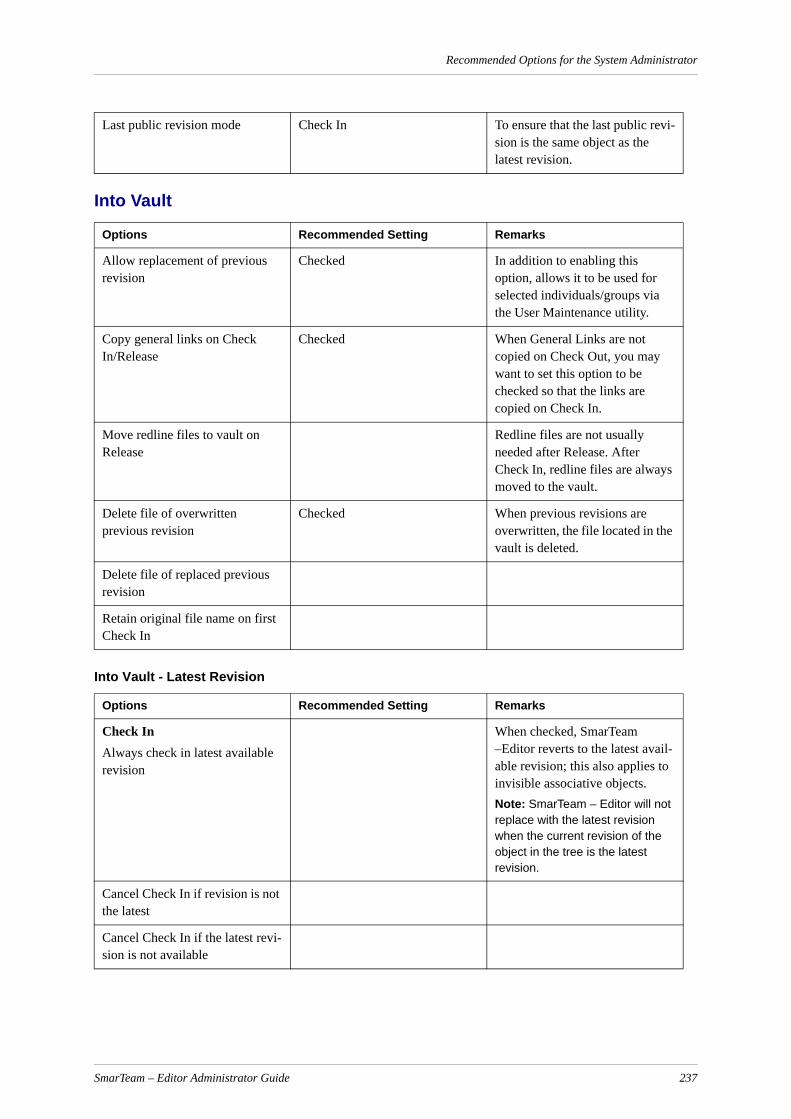
Recommended Options for the System Administrator
Into Vault
Into Vault - Latest Revision
Last public revision mode Check In To ensure that the last public revi-sion is the same object as the latest revision.
Options Recommended Setting Remarks
Allow replacement of previous revision
Checked In addition to enabling this option, allows it to be used for selected individuals/groups via the User Maintenance utility.
Copy general links on Check In/Release
Checked When General Links are not copied on Check Out, you may want to set this option to be checked so that the links are copied on Check In.
Move redline files to vault on Release
Redline files are not usually needed after Release. After Check In, redline files are always moved to the vault.
Delete file of overwritten previous revision
Checked When previous revisions are overwritten, the file located in the vault is deleted.
Delete file of replaced previous revision
Retain original file name on first Check In
Options Recommended Setting Remarks
Check InAlways check in latest available revision
When checked, SmarTeam –Editor reverts to the latest avail-able revision; this also applies to invisible associative objects.Note: SmarTeam – Editor will not replace with the latest revision when the current revision of the object in the tree is the latest revision.
Cancel Check In if revision is not the latest
Cancel Check In if the latest revi-sion is not available
SmarTeam – Editor Administrator Guide 237
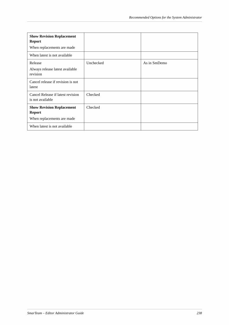
Recommended Options for the System Administrator
Show Revision Replacement ReportWhen replacements are made
When latest is not available
ReleaseAlways release latest available revision
Unchecked As in SmDemo
Cancel release if revision is not latest
Cancel Release if latest revision is not available
Checked
Show Revision Replacement ReportWhen replacements are made
Checked
When latest is not available
SmarTeam – Editor Administrator Guide 238

Recommended Options for the System Administrator
Out of Vault
Out of Vault - Latest Revision
Workflow Options
Options Recommended Setting Remarks
Restrict New Release operation when derived revision exists
Checked When a derived revision exists, most organizations will not allow a New Release operation on the object.
Warn on New Release/Check Out/Copy to remote drive
Allow branching Checked
Copy general links on Check Out/New Release
Checked Preserves links as the document moves from one revision status to another.
Compare revisions before auto-matic replacement of files upon Check Out/Copy
Replace local files on Copy Yes, When not in work A second copy of a file will over-write a duplicate copy of the same file.
Replace local files on Check Out/New Release
Yes, When not in work When a local file is read-only, allows the local copy to be over-written without warning.
Last revision policy for overwrite local files upon Check Out/ Copy
Options Recommended Setting Remarks
Always check out latest available revision
Checked SmarTeam – Editor reverts to the latest available revision (also applies to invisible associative objects).
Cancel check out if revision is not available
Show Revision Replacement ReportWhen replacements are made
Checked
When latest is not available Checked
Options Recommended Setting Remarks
Use Workflow Server Checked Only when the Workflow server is used.
SmarTeam – Editor Administrator Guide 239

Recommended Options for the System Administrator
Send message to supervisor on capture
Allow Life Cycle operations only from Workflow
Initiator can change users in all “Run Time Users” node
Checked Allows the initiator to set users also for nodes not directly connected to the Start node.
SmarTeam – Editor Administrator Guide 240
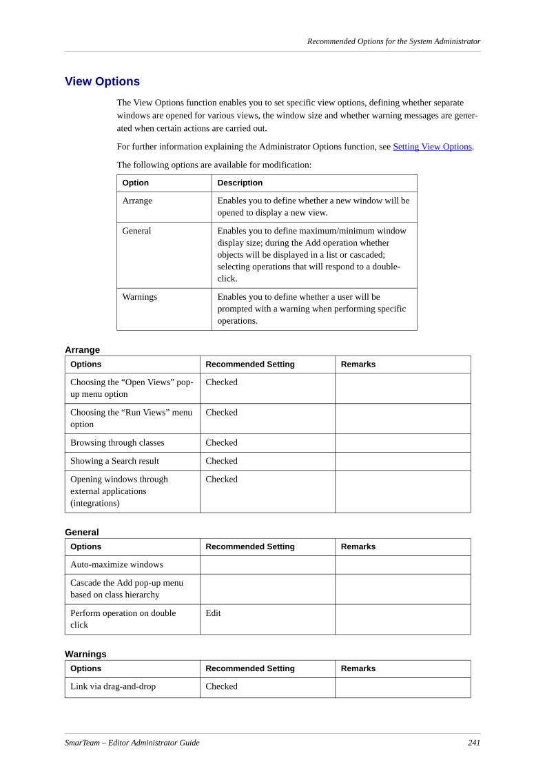
Recommended Options for the System Administrator
View OptionsThe View Options function enables you to set specific view options, defining whether separate windows are opened for various views, the window size and whether warning messages are gener-ated when certain actions are carried out.
For further information explaining the Administrator Options function, see Setting View Options.
The following options are available for modification:
Arrange
General
Warnings
Option Description
Arrange Enables you to define whether a new window will be opened to display a new view.
General Enables you to define maximum/minimum window display size; during the Add operation whether objects will be displayed in a list or cascaded; selecting operations that will respond to a double-click.
Warnings Enables you to define whether a user will be prompted with a warning when performing specific operations.
Options Recommended Setting Remarks
Choosing the “Open Views” pop-up menu option
Checked
Choosing the “Run Views” menu option
Checked
Browsing through classes Checked
Showing a Search result Checked
Opening windows through external applications (integrations)
Checked
Options Recommended Setting Remarks
Auto-maximize windows
Cascade the Add pop-up menu based on class hierarchy
Perform operation on double click
Edit
Options Recommended Setting Remarks
Link via drag-and-drop Checked
SmarTeam – Editor Administrator Guide 241

Recommended Options for the System Administrator
Tree PropertiesThe Tree Properties function enables the System Administrator to initially set the appearance and contents of a Tree. Individual users can override any Tree settings set by the System Administrator and customize them for their own application.
The following options are available for modification:
Recommendations are given only for the following options:
Display Attributes
Expand Settings
The remaining options are left to the discretion of the System Administrator.
Display Attributes
Note: A new key was added to the System Configuration Editor that provides the option to Sort per Creation Date at the domain level. This new feature enables you to view new objects in the Tree.If SortedPerCreationDateDescending = True, the retrieved objects will be sorted per Creation Date Descending.If SortedPerCreationDateDescending = False, the retrieved objects will not be sorted.
Link via Add Checked
Check references on delete Checked
Option Description
Display Fields Enables you to define which attributes will comprise the name of the objects displayed in the Tree.
Visual Setting Enables you to adjust the background color, line color and size, font type and size and zoom factor of the displayed Tree.
Expand Settings Enables you to define the number of hierarchical levels displayed by default.
Sorting Enables you to sort the fields displayed in the Tree by Class Type (as shown in the Class Tree in the Data Model Designer) or by the string of visible attributes that appear in the tree, in ascending or descending order.
Recommended Setting Remarks
ID
Description
Revision
SmarTeam – Editor Administrator Guide 242
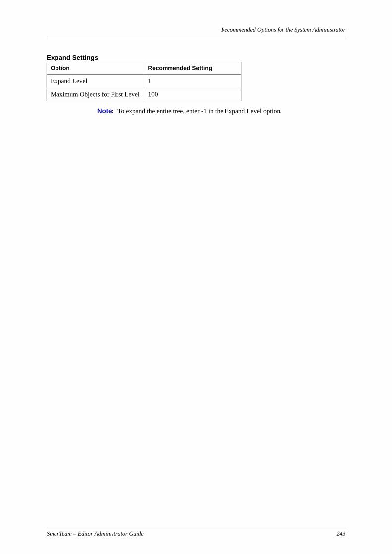
Recommended Options for the System Administrator
Expand Settings
Note: To expand the entire tree, enter -1 in the Expand Level option.
Option Recommended Setting
Expand Level 1
Maximum Objects for First Level 100
SmarTeam – Editor Administrator Guide 243
Data Model Designer
Data Model DesignerIMPORTANT! This utility is applicable for SmarTeam – Editor only and not for any of the SmarTeam integrations.
This section contains:
Launching the Data Model Designer provides instructions for starting the Data Model Designer and describes the main window.
Available Databases presents the complete list of mechanisms available for a SmarTeam database along with their descriptions.
Creating and Defining Classes provides instructions for creating or modifying a template by naming and defining all the Classes and sub-Classes of the SmarTeam data structure.
Defining Indexes and Class Attributes provides instructions for creating and modifying the Attributes (fields) of each Class in the template. These Attributes will be displayed in the Profile Card of a selected object when SmarTeam is implemented. This step also provides instructions for creating an index for the highest level Classes in SmarTeam.
Defining Links and Link Attributes provides instructions for defining Link Classes and Attributes to be assigned to the link between any two data objects and their properties. These Attributes appear in the Links page of SmarTeam – Editor.
Defining Class Composition provides instructions for defining the composition of each Class, i.e., the sub-Classes that can be added to a selected Class in SmarTeam – Editor.
Creating and Modifying a Form provides instructions for creating and modifying a form, the layout for the Profile Card in SmarTeam – Editor.
Creating a SmarTeam Database Structure provides instructions for creating the SmarTeam database structure based on the template defined in the Data Model Designer.
Multi-language Support describes how to use a different language interface in the Data Model Designer and how to select multi-language support in the destination database.
The Data Model Designer Menu Bar describes each option displayed in the menu bar.
Building a SmarTeam StructureThe Data Model Designer enables you to build a SmarTeam database structure precisely suited to your needs, and provides numerous Templates for your selection. Each SmarTeam template is a complete definition of a SmarTeam data structure. It provides different structures for various work environments, such as mechanical engineering, office automation or process organizations. You can select one of these templates and use it as is or customize it to suit the needs of your organization. You can also create a new template of your own.
The Data Model Designer offers you a ready-to-use, template together with complete flexibility to create new templates. A SmarTeam data structure encompasses all the Classes and sub-Classes, including the definitions, attributes and composition assigned to each Class.
The Data Model Designer provides various options to enable you to create a data structure for your own specific business requirements. You can:
SmarTeam – Editor Administrator Guide 244
Data Model Designer
Use the database supplied with the installation (e.g., PLMDB) or modify it for your own requirements, by adding new Classes, changing/deleting existing Classes and attributes, etc. If you modify an existing database without deleting a Class, you can keep all objects stored in the database.
Load a template (WizSrc) to create a new database. (When you define a destination database, the new database will be empty.)
Note: Upon installing SmarTeam, the default password for SmarTeam databases is SMARTDBUSER.
Load a template from another database. You can then change the template and create a new database. This new database will be empty.
Click the Create button to create the database. The new database can be displayed by selecting it from the Available Databases window. This window is displayed by selecting the Switch to Database option from the SmarTeam – Editor File menu.
To further enhance the data structure, SmarTeam provides the Sequence Designer utility. This utility enables you to add a mask name to the Profile Card; refer to Assigning a Mask Name. (A mask name is a formula that SmarTeam uses to automatically increment a number for a specific field in the Profile Card.)
The Data Model Designer provides a completely flexible environment in which you define any hierarchy to suit your needs. The Classes are displayed in a ready-made template and can be used in your SmarTeam database, as is, and can be modified according to your needs.
With the Data Model Designer, you can define the characteristics, properties and behavior of each object and determine the exact attributes and size of the objects. For example, you can define a Class called Items, and then define different kinds of items (sub-Classes) for your exact specifications. Furthermore, the Data Model Designer provides the freedom to design the user interface using various fonts, colors and layouts.
When you select the Create option, SmarTeam automatically creates the data structure based on the template currently defined in the Data Model Designer. When you reopen the SmarTeam – Editor application, it displays the newly created data structure. Refer to Creating a SmarTeam Database Structure for further details.
Before starting the Data Model Designer, we recommend that you carefully organize the data structure you want to create. Sample Data Model Structure provides an explanation to help you organize your planned data structure.
Sample Data Model StructureThe Data Model Designer enables you to build a SmarTeam database structure according to your exact specifications. The Data Model Designer provides numerous templates. Each SmarTeam template is a complete definition of a SmarTeam data structure.
Getting Started: The Data Model
A data model is the abstract SmarTeam data structure. It consists of object types (Classes) and the relationship between those types. Even though the data model is stored in a database, a distinction should be made between the two. Records are physical entities in a relational-database table, whereas objects are abstract entities in an object-oriented data model.
SmarTeam – Editor Administrator Guide 245
Data Model Designer
Basic Concepts
ObjectAn object can be a physical object, a computer file, a person, etc. It is described by a set of properties called attributes. For example, an object of type person may have a Height attribute.
An object's attributes, behavior and identity are defined in its class.
ClassA class is a type of object. For example, you are an object of a Class defined as Person. An Object is an instance of a Class. You, in fact, are an instance of a Person.
A Class is set of objects that share common structure and common attributes. Every engineering entity is an object that can be classified.
Super ClassA Super Class is a special type of class. It is the topmost class in any class tree.
InheritanceA Class can have Subclasses. A Subclass inherits the attributes of its parent Class, as well as other information called methods.
The following example illustrates the advantages of defining Classes in an inherited tree structure. Throughout this example, the following symbols are used:
= Object
= Class
Creating objectsTo explain these concepts we will assume a major automobile manufacturer is building a new line of cars called Swift.
Swift consists of various components, some of which are shown below. Each component is a SmarTeam object.
Swift
Front Wheel
Rear Wheel
Motor
SmarTeam – Editor Administrator Guide 246

Data Model Designer
Creating an object treeThe Swift can now be assembled into an object tree, representing the physical car, as follows:
Defining a class for each objectEach object in the Swift object tree has a type, or is an instance of a Class. The following list shows the Class of each object, together with a few basic attributes that define that object.
Creating a new objectThe same company may also be manufacturing motorcycles, named Rider. The Rider and corresponding Class definition can be defined as follows:
As a result, a new Class structure must be defined.
A Class consists of a Profile Card, an icon and attributes, each of which has a type and size. Furthermore, a Class may have queries, authorization, and scripts defined for it.
Note: The car and the motorcycle Classes have the same attributes. This attribute infor-mation can be reused and inherited by sub-classes.
Convert the Class into a Class TreeThe Class details can be structured to form a Class Tree, as follows.
As a result, abstract classes called Item and Vehicle are created. Objects cannot be created from these Classes. They are created for the sole purpose of reusing their attributes in multiple Classes.
Note: This Class tree is not an Object tree. The Class tree cannot represent assembly relationships between objects; it does not even contain objects.
Summary
The advantage of structuring Classes as a tree is the ability to inherit information. This enables reuse of information, such as attributes, queries, user authorization, scripts, masks, and more.
SmarTeam – Editor Administrator Guide 247

Data Model Designer
Launching the Data Model DesignerThis section describes:
Starting the Data Model Designer
The Data Model Designer window
To start the Data Model Designer:
1 From the Start button on the taskbar select Programs, SmarTeam, Administrative Tools, SmarTeam Data Model Designer.
The SmarTeam Data Model Designer window is displayed.
Creates the SmarTeam database from the selected template
Loads the selected template
Lo
Available templates
Data Model Designer Menu Bar
Selected template icon
Description of the selected template
SmarTeam – Editor Administrator Guide 248
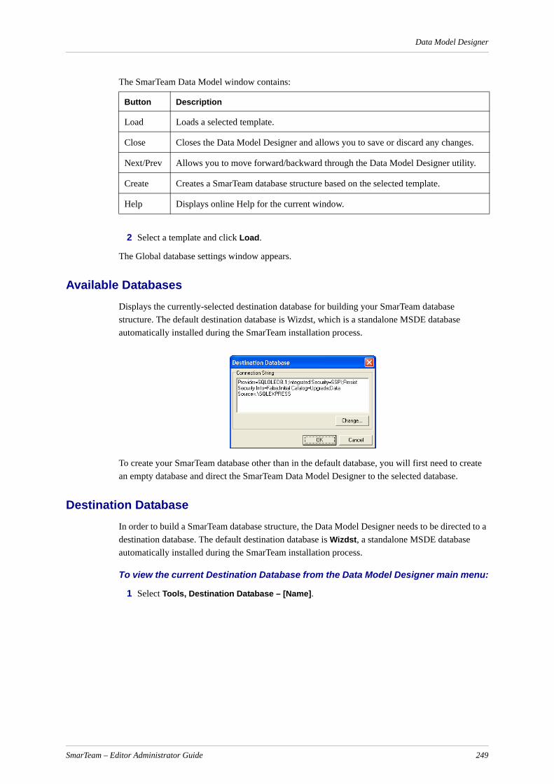
Data Model Designer
The SmarTeam Data Model window contains:
2 Select a template and click Load.
The Global database settings window appears.
Available DatabasesDisplays the currently-selected destination database for building your SmarTeam database structure. The default destination database is Wizdst, which is a standalone MSDE database automatically installed during the SmarTeam installation process.
To create your SmarTeam database other than in the default database, you will first need to create an empty database and direct the SmarTeam Data Model Designer to the selected database.
Destination DatabaseIn order to build a SmarTeam database structure, the Data Model Designer needs to be directed to a destination database. The default destination database is Wizdst, a standalone MSDE database automatically installed during the SmarTeam installation process.
To view the current Destination Database from the Data Model Designer main menu:
1 Select Tools, Destination Database – [Name].
Button Description
Load Loads a selected template.
Close Closes the Data Model Designer and allows you to save or discard any changes.
Next/Prev Allows you to move forward/backward through the Data Model Designer utility.
Create Creates a SmarTeam database structure based on the selected template.
Help Displays online Help for the current window.
SmarTeam – Editor Administrator Guide 249

Data Model Designer
2 To create your SmarTeam database in a different location, you will first need to create a new database to direct the Data Model Designer to the selected database.
3 After creating a location for your selected destination database, from the main menu, select Tools, Destination Database. The Destination Database window is displayed.
4 Select the newly-created database alias from the list and click OK.
As you proceed through the Data Model Designer, the selected database alias is the Destination Database to which templates can be created or modifications made.
Loading a Template
IMPORTANT! To successfully create your SmarTeam database structure, you must load a template, import a template from the database or create a new one.
To load an external template:
Select a template name from the list of templates in the SmarTeam Data Model Designer window and click Load. Or from the Data Model Designer main menu select File, Load Template.
The Load External Template window is displayed.
To load an external template in WizSrc format:
1 From the Data Model Designer menu select File, Load External Template to load a template from an external database type. (A database in WizSrc format is created when a template is built and saved in the Data Model Designer.)
The Load External Template window is displayed.
SmarTeam – Editor Administrator Guide 250

Data Model Designer
2 Select a database from the list.
3 Continue with Entering a Password.
Importing a Template from a Database
To import a template from a destination database type (WizDst format):
1 From the Data Model Designer menu select File, Import Template from Database.
The Available Databases window appears, listing the database files.
2 Select a database from the list and click OK.
Entering a PasswordThe Database Password for [Database] window appears.
To specify a password:
1 Enter the applicable Password then click OK.
A list of available mechanisms is displayed in the Available Mechanisms window.
SmarTeam – Editor Administrator Guide 251
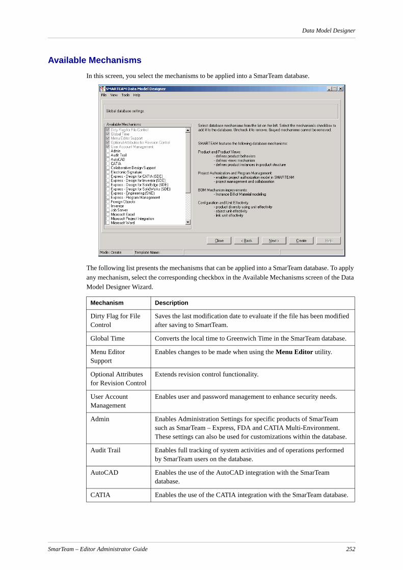
Data Model Designer
Available MechanismsIn this screen, you select the mechanisms to be applied into a SmarTeam database.
The following list presents the mechanisms that can be applied into a SmarTeam database. To apply any mechanism, select the corresponding checkbox in the Available Mechanisms screen of the Data Model Designer Wizard.
Mechanism Description
Dirty Flag for File Control
Saves the last modification date to evaluate if the file has been modified after saving to SmartTeam.
Global Time Converts the local time to Greenwich Time in the SmarTeam database.
Menu Editor Support
Enables changes to be made when using the Menu Editor utility.
Optional Attributes for Revision Control
Extends revision control functionality.
User Account Management
Enables user and password management to enhance security needs.
Admin Enables Administration Settings for specific products of SmarTeam such as SmarTeam – Express, FDA and CATIA Multi-Environment. These settings can also be used for customizations within the database.
Audit Trail Enables full tracking of system activities and of operations performed by SmarTeam users on the database.
AutoCAD Enables the use of the AutoCAD integration with the SmarTeam database.
CATIA Enables the use of the CATIA integration with the SmarTeam database.
SmarTeam – Editor Administrator Guide 252
Data Model Designer
Collaborative Design Support
Enables working in a shared workspace with the SmarTeam database.
Distributed Enables working in a Multi-Site environment on the SmarTeam database.
Electronic Signature Enables implementing Electronic Signatures on SmarTeam objects.
Express - Design for CATIA (SDE)
Implements SmarTeam Design Express for CATIA in the SmarTeam database.
Express - Design for Inventor (SDE)
Implements SmarTeam Design Express for Inventor in the SmarTeam database.
Express - Design for SolidEdge (SDE)
Implements SmarTeam Design Express for Solid Edge in the SmarTeam database.
Express - Design for SolidWorks (SDE)
Implements SmarTeam Design Express for SolidWorks in the SmarTeam database.
Express - Engineering (SNE)
Implements SmarTeam Engineering Express for BOM and Process Management in the SmarTeam database.
Express - Program Management
Implements SmarTeam Express Program Management in the SmarTeam database.
Job Server Enables a special server-side application that remotely automates tasks and optimizes approval processes in a compliance-ensured environmentThis application runs in silent mode and performs Lifecycle or other operations on documents, e.g., Release operation on CAD documents.
Foreign Objects Enables foreign objects from external applications in the SmarTeam database
Inventor Enables the use of the Inventor integration with the SmarTeam database.
Microsoft Excel Enables the use of the Microsoft Excel integration with the SmarTeam database.
Microsoft Word Enables the use of the Microsoft Word integration with the SmarTeam database.
Microsoft Project Integration
Enables the use of the Microsoft Project integration with the SmarTeam database for working with the Program Management mechanism.
Multi-States Mechanism
Extends lifecycle capabilities in the SmarTeam database for Parts and Documents mechanism.
Parts and Documents
Adds Item and BOM lifecycle management to the SmarTeam database and creates a specification relation between items and documents.Note: To implement item definitions, the item class must be revision-managed and the Multi-States mechanism be checked.
Note: The DMD run time may be long if a customer has an Items class in their Database that was not created with Parts and Documents behavior.
Product Adds the Product Management data model and Configuration Views definitions in the SmarTeam database.
Mechanism Description
SmarTeam – Editor Administrator Guide 253
Data Model Designer
Dependencies between Mechanisms
When adding specific mechanisms, additional mechanisms may be added automatically. For example, when adding the CATIA mechanism, the Microsoft Excel, AutoCAD, Inventor, Autodesk Mechanical Desktop, Microsoft Word, Solid Edge, SolidWorks and Pro/ENGINEER mechanisms are added automatically and are selected in the Available Mechanisms list.
The following table presents a complete list of Domain Level Behavior dependencies as defined in the WizSrc database:
Project Based Authorizations
Enables the definition of secured project data in the SmarTeam database and the setting of authorizations per role in a project.
Program Management
Enables the management of project tasks, resources and deliverables in the SmarTeam database.
SmartBOM Enables BOM management functionality in the SmarTeam database.
SmartGateway Adds an interface for data import/export from the SmarTeam database.
SmartWeb3.0 Enables the use of SmarTeam – Web Editor on the SmarTeam database.
Solid Edge Enables the use of the Solid Edge integration with the SmarTeam database.
SolidWorks Enables the use of the SolidWorks integration with the SmarTeam database.
Vault Replication Enables the user of vault replication on the SmarTeam vaults.
Work Flow Adds SmarTeam – Workflow functionality in the SmarTeam database.
Mechanism Description
Leading DLB Dependant DLB
Smarteam Menu Editor Support
Work Flow Message
SolidWorks Admin
SolidWorks AutoCAD
SolidWorks CATIA
SolidWorks Inventor
SolidWorks Excel
SolidWorks Word
SolidWorks Solid Edge
CATIA Admin
CATIA Microsoft Excel
CATIA AutoCAD
CATIA Inventor
CATIA Microsoft Word
SmarTeam – Editor Administrator Guide 254
Data Model Designer
Creating and Defining ClassesThis step describes how to modify the selected template by creating new Classes and sub-Classes, and how to define each object in the template.
In this step, you will learn the following:
Adding a Class
Deleting a Class
Defining a Class
Selecting an Open, Close or Leaf Icon
Adding a Class
To add a Class:
1 Select the Classes icon. The Sample Entities window is now displayed.
The Sample Entities window enables you to add or delete sub-classes to the template.
Note: The Classes displayed in the Selected field (when Classes is selected) are the highest level Classes in the SmarTeam data structure, and are referred to as Super-Classes. Each Super-Class has its own Default Hierarchical Link. In the SmarTeam – Editor application, each of these Super-Classes has a Class button in the SmarTeam – Editor toolbar, which when clicked, opens a window displaying its own tree browser.
The following fields and buttons appear in the Sample Entities window:
Selected box: Lists the lower level Classes (sub-Classes) of the selected Class:
CATIA Solid Edge
CATIA SolidWorks
CATIA Pro/ENGINEER
Parts and Documents Multi States Mechanism
Parts and Documents Product
Product Parts and Documents
Product Multi States Mechanism
Project Based Authorizations Multi States Mechanism
SmartWeb30 Common DLB for SmarTeam Web applications such as MySmarTeam and SmartWeb
Job Server Admin
Electronic Signature Work Flow
Electronic Signature Admin
Microsoft Project Integration Multi States Mechanism
SmarTeam – Editor Administrator Guide 255

Data Model Designer
When the Classes icon is selected, the Selected box lists the highest level Classes of the data structure (for example Projects, Documents, etc.).
When a specific Class icon is selected, the Selected box lists its sub-Classes. For example: When Documents is selected, its sub-Classes Folder, Document, CAD files and Offline Documents are displayed in the Selected box.
Sample Entities: Displays a list of sample Classes from which you can select one or more Classes and move them to the Selected box, to place them in the template. These samples are provided by SmarTeam or were previously removed from the Selected box and placed there.
Arrow Buttons: These buttons enable you to move selected Class(es) between the Selected and Sample Entities boxes, to place and remove Classes in the template.
Enter your own: If applicable, enter a new Class name.
Add: Click Add to add a new Class or sub-Class to the template.
Delete: Click Delete to delete a Class (and all its sub-Classes) from the template.
2 You can add a new Class by entering a new Class name in the Enter your own field and click Add. This name now appears in the Selected box and the template and is displayed in the Tree. A Class name can be up to 32 characters. Punctuation or special control characters are not permitted, except for an underscore.
In the example below, the Class Personnel is added to the template:
Click Add to add the new class to the Template
SmarTeam – Editor Administrator Guide 256
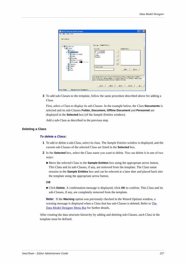
Data Model Designer
3 To add sub-Classes to the template, follow the same procedure described above for adding a Class.
First, select a Class to display its sub-Classes. In the example below, the Class Documents is selected and its sub-Classes Folder, Document, Offline Document and Personnel are displayed in the Selected box (of the Sample Entities window).
Add a sub-Class as described in the previous step.
Deleting a Class
To delete a Class:
1 To add or delete a sub-Class, select its class. The Sample Entities window is displayed, and the current sub-Classes of the selected Class are listed in the Selected box.
2 In the Selected box, select the Class name you want to delete. You can delete it in one of two ways:
Move the selected Class to the Sample Entities box using the appropriate arrow button. This Class and its sub-Classes, if any, are removed from the template. The Class name remains in the Sample Entities box and can be selected at a later date and placed back into the template using the appropriate arrow button.
OR
Click Delete. A confirmation message is displayed; click OK to confirm. This Class and its sub-Classes, if any, are completely removed from the template.
Note: If the Warning option was previously checked in the Wizard Options window, a warning message is displayed when a Class that has sub-Classes is deleted. Refer to The Data Model Designer Menu Bar for further details.
After creating the data structure hierarchy by adding and deleting sub-Classes, each Class in the template must be defined.
SmarTeam – Editor Administrator Guide 257
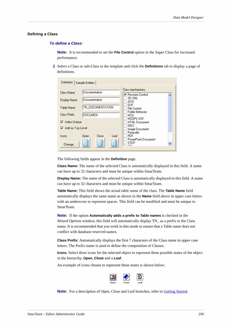
Data Model Designer
Defining a Class
To define a Class:
Note: It is recommended to set the File Control option in the Super Class for increased performance.
1 Select a Class or sub-Class in the template and click the Definitions tab to display a page of definitions.
The following fields appear in the Definition page.
Class Name: The name of the selected Class is automatically displayed in this field. A name can have up to 32 characters and must be unique within SmarTeam.
Display Name: The name of the selected Class is automatically displayed in this field. A name can have up to 32 characters and must be unique within SmarTeam.
Table Name: This field shows the actual table name of the class. The Table Name field automatically displays the same name as shown in the Name field above in upper case letters with an underscore to represent spaces. This field can be modified and must be unique to SmarTeam.
Note: If the option Automatically adds a prefix to Table names is checked in the Wizard Options window, this field will automatically display TN_ as a prefix to the Class name. It is recommended that you work in this mode to ensure that a Table name does not conflict with database reserved names.
Class Prefix: Automatically displays the first 7 characters of the Class name in upper case letters. The Prefix name is used to define the composition of Classes.
Icons: Select three icons for the selected object to represent three possible states of the object in the hierarchy, Open, Close and a Leaf.
An example of icons chosen to represent these states is shown below:
Note: For a description of Open, Close and Leaf branches, refer to Getting Started.
SmarTeam – Editor Administrator Guide 258

Data Model Designer
Add as top level: Check this option to define the object as a root object in the hierarchy tree.
Index Unique: Check this option to add a unique identifier to this Class.
Class Mechanisms
Revision Control: This option enables lifecycle management of the selected Class. When this field is checked, SmarTeam will manage the lifecycle of the objects in this Class and add the following functionality:
Revisions page in SmarTeam – Editor.
Revision-Management options (Check In, Check Out, Release).
Attributes (fields) will automatically appear in the template and in its Profile Card, such as:
Revisions
Effectivity From
Effectivity To
and others
File Control: In this option you specify that the objects in this Class represent a file. For example, you can decide that a Projects Class or Folder Class do not have the File Control option, but Documents, Drawings, Specs, Items will have File Control. These objects in SmarTeam will each represent a file and add the following functionality:
Viewer Page
File options (Edit, View, Redline, Print).
Attribute fields will automatically appear in the template and in its Profile Card, such as:
File Name
File Type
and others
WorkFlow/Catia/ACAD/Inventor/Mechanical Desktop/ProE/Solid Edge/SolidWorks/Microstation: Each of these options is available if the corresponding option was selected at the start of the Data Model Designer utility. See Available Mechanisms for details.
Selecting an Open, Close or Leaf Icon
To select an icon (Open, Close or Leaf) which will appear in the tree browser in SmarTeam – Editor:
1 In the Definition page click on the Select Icons button to open the Icon Browser window below.
Note: You can also use the Icon Browser to select an icon that represents a template in the first Wizard window.
2 Click one of the icon boxes to designate whether the selected icon will be Open, Close or Leaf.
3 Click an icon from this browser or display icons from a different directory. The selected icon is placed in the appropriate icon box.
SmarTeam – Editor Administrator Guide 259
Data Model Designer
Note: To ensure clarity, the size (in pixels) of each icon should not exceed 24 by 24 pixels.
To add more icons to the Icon Browser window:
1 Click Directory to display a standard Windows selection window.
2 Select a directory and click OK. The Icon Browser will now display icons from the newly-selected directory. Refer to the SmarTeam – Editor Online Help for details about the Icon Browser.
Note: Only graphic files with .bmp and .ico extensions are displayed in the Icon Browser.
3 Click one of the icon boxes (Open, Close or Leaf) and select an icon. The selected icon is placed in the appropriate icon box.
4 Click OK to return to the Icon Browser definition window.
5 Click Next to proceed to the next step in building your template.
The next window displays the attribute fields of each Class in the template, allowing you to add and delete attributes.
Defining Indexes and Class AttributesAs described in the Getting Started, each Class has its own Profile Card that displays the Attributes of the selected object.
In this step, you will learn how to:
Add or delete Attributes
Define an Attribute
Assign a Reference Class to an Attribute. (A Reference Class is a visual reference to a different SmarTeam Class that can be placed in a Profile Card.)
Assign a Lookup Table to an Attribute. (A Lookup Table is a dropdown list that appears in the Profile Card for the selected Attribute.)
Define the Index of a Class. (An Index is the primary identifier of each object in SmarTeam. An Index is assigned to each of the main Super-Classes in the template. For example, an index is assigned to Projects and those Classes directly below it (Projects, Documents, Users).
Adding/Deleting Attributes
To add or delete Attributes:
1 In the template, click on the Fields icon of a Class to view its current attributes in the Selected box in the Sample Entities page.
The template displays a list of fields (attributes) for each Class.
Note: If the Fields icon is not displayed, double-click on the Class icon above it to display a list of fields.
For each Class in the template, attributes are inherited from its higher level Classes. The lower-level branch only displays the new attributes added to the selected Class. Class attributes include inherited attributes in addition to their own attributes.
SmarTeam – Editor Administrator Guide 260

Data Model Designer
For example, the illustration above displays the fields (attributes) for the Documents Class. If the Documents Class has 11 attributes, then its sub-classes (Folder, Document, Offline Documents, Personnel and Reports) will inherit all these 11 attributes. If you add four new attributes to the class Document, it will then have 15 attributes.
The Drawing autoform, which is automatically generated at the end of the setup, will display all 15 attributes. Note that the template only displays the four additional attributes for Drawing, and not the 11 inherited attributes.
Note: Autoform is the layout for the Profile Card. Refer to Creating and Modifying a Form for further information.
2 In the Sample Entities page you can add and delete attributes in the same way as Classes are added and deleted from the template.
To add an attribute, select one from the Sample Entities window and move it to the Selected window, or enter your own attribute then click Add. Attributes reserved for the system (listed below) cannot be added.
To delete an attribute, move it to the Sample Entities box or click Delete.
Refer to Creating and Defining Classes for a description of the Sample Entities window and operating instructions on adding and deleting Classes.
Note: If the Automatically add prefix to column names option is checked in the Wizard Options window, a new field name will be displayed with a CN_ prefix. Refer to The Data Model Designer Menu Bar for further details. It is recommended that you work in this mode to ensure that all column (attribute) names are unique and are not reserved, (i.e., names used in the SmarTeam internal structure).
IMPORTANT! The following reserved system attributes cannot be added as new attributes:
Each attribute must be defined to determine how it will be maintained in the database and displayed in the Profile Card when SmarTeam is implemented.
REVISION_STG DIRECTORY
USER_OBJECT_ID OBJECT_ID
PHASE CLASS_ID
REVISION STATE
PAR_REVISION CREATION_DATE
APPROVAL_DATE OBJECT_ID
EFFECTIVE_FROM CLASS_ID
EFFECTIVE_UNTIL OBJECT_ID1
UNDER_OPERATION CLASS_ID1
CAD_REF_DIRECTORY OBJECT_ID2
CAD_REF_FILE_NAME CLASS_ID2
VAULT_OBJECT_ID DESCRIPTION
FILE_TYPE VALUE_ORDER
FILE_NAME
SmarTeam – Editor Administrator Guide 261

Data Model Designer
Defining an Attribute
To define an Attribute:
1 Click an attribute in the template to display the Definition window.
2 Fill in the fields in the Definition window. Different fields in the Definition window are enabled depending on the type of attribute selected in the Type field.
The Definition window fields are described below.
Note: Some fields are automatically locked (disabled). For example, the Size field is locked when the attribute Type is defined as a date.
Name: Automatically displays the name that SmarTeam assigns to the selected object. The name is displayed in uppercase only and an underscore replaces spaces between words.
SmarTeam – Editor Administrator Guide 262

Data Model Designer
Type: Click the Type field dropdown arrow to display a dropdown list of attribute types that can be placed in this field in the Profile Card and select one from the list.
Note: For all string types (Char, String4000, Memo), "[ ]"(square brackets) within an SQL statement will be ignored in a Search operation.
In addition, the filename/path should not contain "[ ]" (square brackets) as a SmarTeam query cannot differentiate between "filename.ext" and "[filename].ext.
Type Description
Integer Numeric only. Range: 32768..32767.
Char Character only. The Size, Language and Sensitive fields in the Definitions window can be modified.
Long Integer
Long integer. -Range 2147483648..2147483647.
Double Precision
Double precision number. -Range 1.7*10e308..5.0*10e-324.
Date Date browser
Lookup Table
Drop-down list. The table name must be defined in the Lookup field of the Definitions window. Refer to Assigning a Lookup Table to an Attribute for details.
Reference to Class
Dropdown multi-column list. This list enables you to create a visual reference to an object in a different Class. The referenced Class must be defined for that field. Refer to Assigning a Reference Class to an Attribute for details.
Effective Date From
Date browser
Effective Date Until
Date browser
Time Stamp Date and time of object creation.
Relative Time
Control for measuring time in days, hours, minutes and seconds.
Boolean Attribute for Boolean expressions.
Memo Text data that is unrestricted in size. Only one Class attribute can be assigned to this type.
Note: SmarTeam supports only case-sensitive queries for fields of type Memo.
URL Field for entering a URL address, allowing the selected Web page to be opened in your default browser. The selected Web page can also be displayed in a defined field in the Profile Card.
SmarTeam – Editor Administrator Guide 263

Data Model Designer
Note: The SmarTeam data model does not support the definition of attributes with iden-tical names and different types. If a new attribute conflicts with an existing attribute, you must either rename the new attribute or select the same type as that of the original attribute.If a new attribute conflicts with more than one existing attribute, please contact SmarTeam Global Technical Support for assistance.
Size: Automatically shows the number of bytes in this field. The size can be modified when Char is selected in the Type field. (The maximum number of available characters is 255.)
Language: Enabled only when Char is selected in the Type field. English is displayed by default. To change languages, open the Language dropdown list and select a language from the list.
Sensitive: Determines how data is displayed and handled in the selected attribute field of the Profile Card. The following options can be selected:
Case Sensitive: SmarTeam distinguishes between uppercase and lowercase characters, and a user can enter both character types. For example, the words New and new are two different words.
Note: To maintain the case-sensitivity of the name of a file that takes part in a lifecycle operation, make sure that its fields are defined as Case Sensitive in the Sensitive field in the Data Model Designer. This must be done for both the File Name field and the Application Reference File Name field.
Upper Case: All the characters in the field will be displayed as uppercase characters regardless of how they are entered (according to ISO-9000 and MIL standards).
Lower Case: All characters in the field will be displayed as lowercase characters regardless of how they are entered.
Default Wide: The characters in the field will be displayed as determined by system-wide preferences. This option is not yet implemented.
Mandatory: Check this option to indicate that the selected attribute field is mandatory in the Profile Card. When the user defines a new object in SmarTeam, data must be entered in this field before proceeding.
Reference: Only displayed if Reference to Class was selected in the Type field. In this field, you can select or change the Class linked to the attribute. Refer to Assigning a Reference Class to an Attribute for details.
Lookup: Only displayed if Lookup Table was selected in the Type field. In this field, you can select the dropdown list (Lookup Table) to be displayed in the Profile Card. When a user clicks on the dropdown arrow in this field, a dropdown list of options will appear. Refer to Assigning a Lookup Table to an Attribute for details.
Display: Shows the name of the selected attribute exactly as displayed in the Profile Card. Note that this field may differ from the Name field described earlier.
Description: Enter a description for the selected attribute. When performing an update, the description is displayed in the SmarTeam status bar. The status bar appears in the lower left side of the window, when the user clicks on this attribute in the Profile Card.
Display Order tab: Defines which attribute should be displayed by default in grid results:
When no grid properties or projection were set in the tree properties; or
SmarTeam – Editor Administrator Guide 264

Data Model Designer
In Reference to Class when no projection was set.
Note: The display attributes for a class can be defined in the Defining an Attribute step when selecting a class. The display attributes selected for class users,will be displayed in all the user selection windows in SmarTeam.
Changes in the Data Model Designer for Adding AutoCAD Drawings to the Database
Before adding an AutoCAD drawing to the database using a SmarTeam – AutoCAD Integration, the following changes should be made in the Data Model Designer:
1 From the Define class attributes and indexes step, in the Fields Browser, select Class, Fields:
2 In the Sample Entities tab, define the following four entities as Case Sensitive in the Sensitive field (see Case Sensitive for details):
FILE_NAME DIRECTORY CAD_REF_FILE_NAME CAD_REF_DIRECTORY
Assigning a Reference Class to an Attribute
A Reference Class attribute is an attribute that is linked to a different Class. Creating a Reference Class attribute is a two-step process:
Step 1: In the Data Model Designer, define an attribute as a Reference to Class attribute and select a Reference Class. For example, you may define a Folder attribute named cn_proj as a Reference to Class attribute and select the Projects Class as its Reference Class.
Step 2: In the Form Designer, create a MultiCombo (Reference) field and define the attributes of the referenced Class (in our example, Projects) to be displayed in the Profile Card. (Refer to the Creating a Multi-combo (Reference) Field for instructions.)
SmarTeam – Editor Administrator Guide 265

Data Model Designer
The folder Profile Card contains a Reference field to the Projects Class. The user can select a Project to display in this field. The selected Project attributes are then displayed (such as Creation Date and Project Description).
Notes:
a RefToClass attributes are not listed in the available fields of the Display Order tab in Class Attributes. This is due to the fact that the Display Order defines the order of attributes in a grid, and the RefToClass attribute is displayed as a grid of attributes.
b When many Reference to Class attributes are assigned to a class, the first loading of an object of this class after you open the Editor may take some time, as the operation loads all of the references of these attributes to the cache.
To assign a Reference Class to an Attribute:
1 Create an attribute that will serve as a Reference to Class attribute, such as cn-proj in the Folders Class.
2 In the Type field of the Definition window, select Reference To Class for the selected attribute.
3 A Class Tree Window is automatically displayed.
Class Tree Window
The Class Tree window presents the tree of all the classes and sub-classes defined in the database.
To select a class:
1 In the Class Tree window, select a Class and click OK.
2 The selected Class is displayed in the Reference field. To change the linked Class, click the button to the right of this field to re-display the Class Tree window.
Assigning a Lookup Table to an Attribute
A Lookup Table is a dropdown list that appears in the Profile Card for the selected attribute. For example, if you assign the Lookup Table named File Type to the File attribute, then in the Profile Card a dropdown arrow will be shown in the File field. In this field, the user can display a dropdown list of file types and select one.
SmarTeam – Editor Administrator Guide 266

Data Model Designer
The options (values) that appear in the dropdown list are assigned in the SmarTeam – Editor application by selecting Tools, Lookup Table in the SmarTeam – Editor main menu. Refer to Creating a Lookup Field.
To assign a Lookup Table to an Attribute:
1 Click the Browse button in the Lookup field to display the Lookup Tables window.
2 Click on the Select tab to display the Select window. Select a Lookup Table from the list and click OK. The selected Lookup Table is now assigned to the attribute. In the Profile Card, the options for the selected Lookup Table appear in a dropdown list for this attribute.
3 In the Lookup Tables window click on the Maintenance tab or in the Data Model Designer main menu select Tools, Lookup Tables to display the Lookup Tables on the Maintenance page.
4 Select a name from the Sample Entities box on the right and move it to the Recommendation box.
OR
Enter a new name in the Enter your own field and click Add.
5 Click Close to save your changes.
Defining the Index of a Class
Super-Classes, (the highest level of Classes in the template), such as Projects, Documents, Materials, Items and Contacts must each have an Index. The Index is a unique primary identifier for each object in SmarTeam. It is comprised of one or more selected attributes. The Revision attribute is always appended when a Class is revision managed.
For example, for the Documents Class, the Index may be comprised of the attribute Document No and the attribute Revision (by default). If a document has two different revisions, each one will have a different Index. For example: one document may be named K32a and another may be named K32b; the a and b reflect the different revisions of the document. To emphasize the importance of the Index, it is displayed on a yellow background in the Profile Card.
Note: The Index field must be unique within SmarTeam.
The Index is the Primary ID field when the user displays the Single View. See SmarTeam – Editor Display Views for details.
The user can then enter the Primary ID to quickly locate any object. The Index can also be used in Searches and error messages to designate the object.
To define the Index of a Class:
1 In the template, click on a Class and then click the Index tab to display the Index window.
Note: The Index window is only displayed when a high-level Class (Super-Class) is selected in the template.
The Available Attributes window displays all attributes of the selected Class. The Ordered Attributes window displays the attributes that comprise the Index.
SmarTeam – Editor Administrator Guide 267
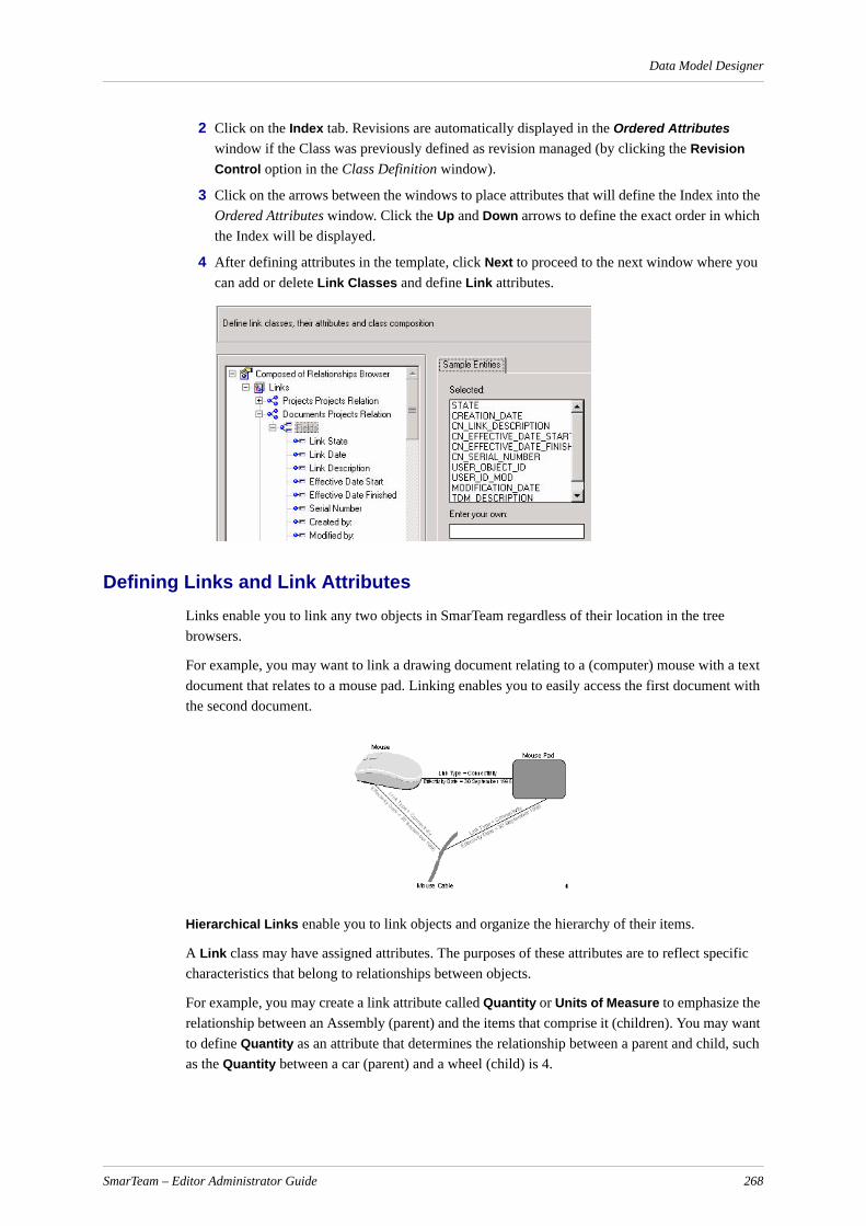
Data Model Designer
2 Click on the Index tab. Revisions are automatically displayed in the Ordered Attributes window if the Class was previously defined as revision managed (by clicking the Revision Control option in the Class Definition window).
3 Click on the arrows between the windows to place attributes that will define the Index into the Ordered Attributes window. Click the Up and Down arrows to define the exact order in which the Index will be displayed.
4 After defining attributes in the template, click Next to proceed to the next window where you can add or delete Link Classes and define Link attributes.
Defining Links and Link AttributesLinks enable you to link any two objects in SmarTeam regardless of their location in the tree browsers.
For example, you may want to link a drawing document relating to a (computer) mouse with a text document that relates to a mouse pad. Linking enables you to easily access the first document with the second document.
Hierarchical Links enable you to link objects and organize the hierarchy of their items.
A Link class may have assigned attributes. The purposes of these attributes are to reflect specific characteristics that belong to relationships between objects.
For example, you may create a link attribute called Quantity or Units of Measure to emphasize the relationship between an Assembly (parent) and the items that comprise it (children). You may want to define Quantity as an attribute that determines the relationship between a parent and child, such as the Quantity between a car (parent) and a wheel (child) is 4.
SmarTeam – Editor Administrator Guide 268

Data Model Designer
In the SmarTeam Schema, Link Classes can be divided to several groups according to their origin and available operations:
Link Class Description
Automatic Links For example, the link between MAIN_CLASS (as a rule "Projects") and all user-defined Classes. These Links are automatically created and cannot be deleted. User-defined attributes can be added to or deleted from them.
Default Hierarchical Links These links are automatically created for each super class and cannot be deleted. User-defined attributes can be added to them or deleted from them.
Automatic Links, Links defined in Domain Behaviors assigned to a Schema
Links are automatically created and cannot be deleted. User-defined attributes can be added to or deleted from them.
Links defined between super classes
The user defines these links. A user can define more than one link between super classes. User-defined attributes can be added to or deleted from these links. In this step, you can:
Add and delete user-defined Link Classes.
Define Link Class properties, including icons representing Normal and Reverse Links and icons representing the parent and child state for objects linked by default hierarchical links.
Define Link Class attributes assigned to the Link between any two data objects linked by this Link Class. For example, you can add Link State and Link Date as Link attributes of some Link Class. These attributes will later appear in the Links page of SmarTeam – Editor, Define Index Attributes of Link Classes.
Define the display order for Attributes of Link Classes.
SmarTeam – Editor Administrator Guide 269
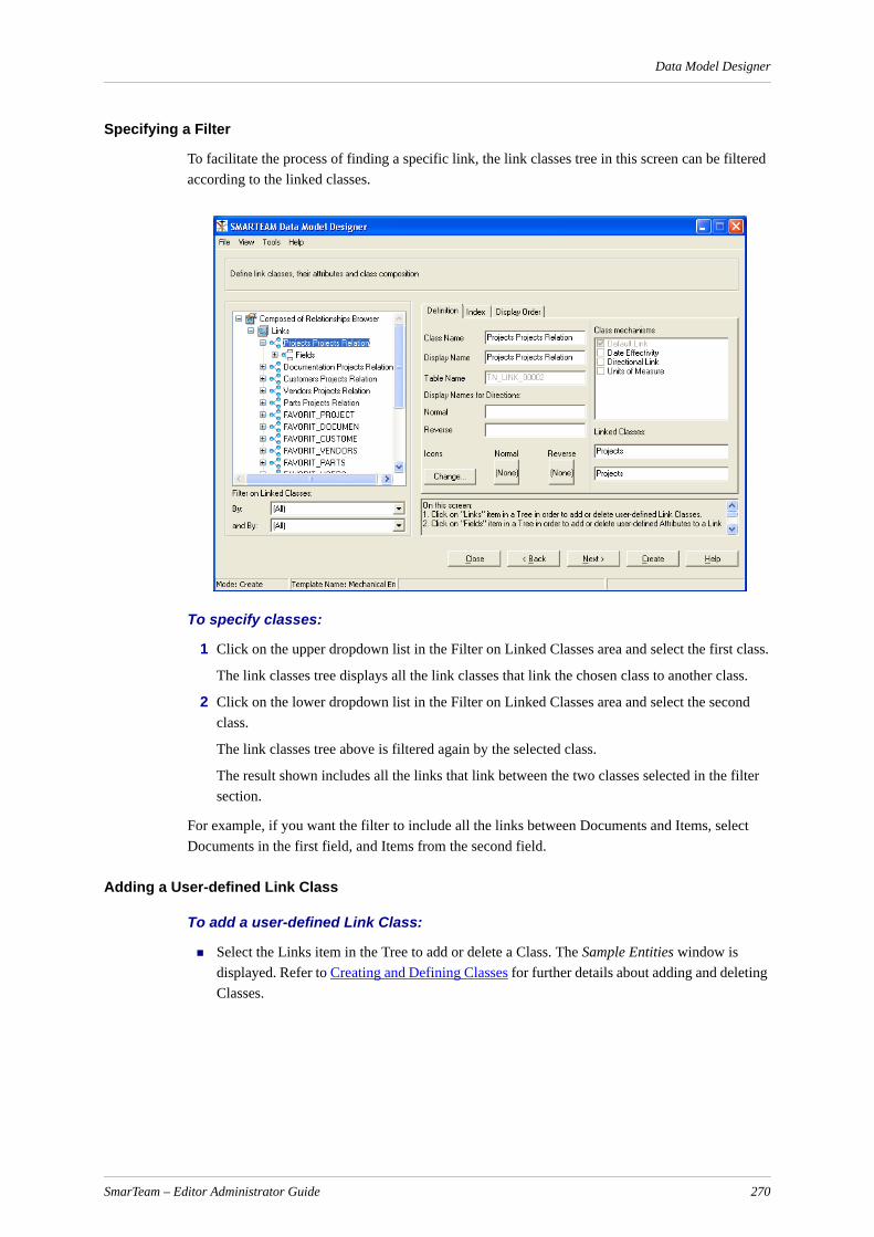
Data Model Designer
Specifying a Filter
To facilitate the process of finding a specific link, the link classes tree in this screen can be filtered according to the linked classes.
To specify classes:
1 Click on the upper dropdown list in the Filter on Linked Classes area and select the first class.
The link classes tree displays all the link classes that link the chosen class to another class.
2 Click on the lower dropdown list in the Filter on Linked Classes area and select the second class.
The link classes tree above is filtered again by the selected class.
The result shown includes all the links that link between the two classes selected in the filter section.
For example, if you want the filter to include all the links between Documents and Items, select Documents in the first field, and Items from the second field.
Adding a User-defined Link Class
To add a user-defined Link Class:
Select the Links item in the Tree to add or delete a Class. The Sample Entities window is displayed. Refer to Creating and Defining Classes for further details about adding and deleting Classes.
SmarTeam – Editor Administrator Guide 270
Data Model Designer
Deleting a Link Class
To delete a Link Class:
In the Sample Entities box, select the Link Class name you want to delete and click Delete. A confirmation message is displayed; click OK to confirm.
Defining Link Class Properties
To define Link Class properties:
Click on a Class in the Tree and choose the Definition tab. Refer to Creating and Defining Classes for further details about defining Class properties.
Note: You can differentiate between Links and Default Hierarchical Links in the Class Tree by their icons.
A Link Class that includes user-defined links cannot be changed. Therefore, Linked Classes are presented as read-only on the screen.
Adding/Deleting Link Attributes
To add or delete Link Attributes:
1 Click on the Fields icon in the template to display the Sample Entities window.
If an attribute is not required, use the arrow buttons to remove it from the Selected window to the Sample Entities window.
2 To delete an attribute, move it to the Sample Entities box or click Delete. Refer to Creating and Defining Classes for a description of the Sample Entities window and operating instructions on adding and deleting a Class.
Defining the Characteristics of the Link Attributes
To define the characteristics of the Link Attributes:
1 Click on an attribute to display the Definition window.
These fields are identical to those in the previous Definition window that described Class attributes.
2 Enter the definitions for the Link attribute.
Defining the Index Attributes of a Link Class
To define Index Attributes of Link Class:
Click on a Class in the Tree and choose the Index tab. Refer to Defining Indexes and Class Attributes for further details about defining Index Attributes of Link Class.
Defining the Display Order for the Attributes of a Link Class
To define display order for Attributes of Link Class:
Click on a Class in the Tree and choose the Display Order tab. Refer to Defining Indexes and Class Attributes for further details about defining display order of Attributes of a Class.
SmarTeam – Editor Administrator Guide 271
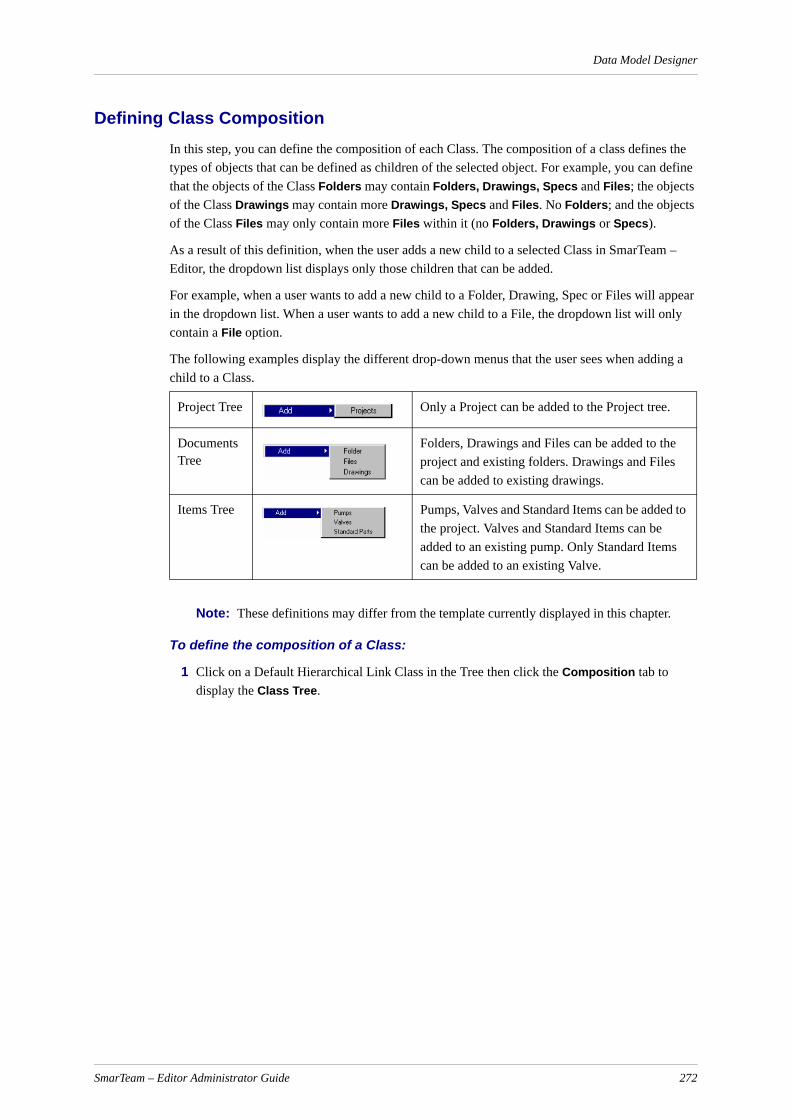
Data Model Designer
Defining Class Composition In this step, you can define the composition of each Class. The composition of a class defines the types of objects that can be defined as children of the selected object. For example, you can define that the objects of the Class Folders may contain Folders, Drawings, Specs and Files; the objects of the Class Drawings may contain more Drawings, Specs and Files. No Folders; and the objects of the Class Files may only contain more Files within it (no Folders, Drawings or Specs).
As a result of this definition, when the user adds a new child to a selected Class in SmarTeam – Editor, the dropdown list displays only those children that can be added.
For example, when a user wants to add a new child to a Folder, Drawing, Spec or Files will appear in the dropdown list. When a user wants to add a new child to a File, the dropdown list will only contain a File option.
The following examples display the different drop-down menus that the user sees when adding a child to a Class.
Note: These definitions may differ from the template currently displayed in this chapter.
To define the composition of a Class:
1 Click on a Default Hierarchical Link Class in the Tree then click the Composition tab to display the Class Tree.
Project Tree Only a Project can be added to the Project tree.
Documents Tree
Folders, Drawings and Files can be added to the project and existing folders. Drawings and Files can be added to existing drawings.
Items Tree Pumps, Valves and Standard Items can be added to the project. Valves and Standard Items can be added to an existing pump. Only Standard Items can be added to an existing Valve.
SmarTeam – Editor Administrator Guide 272
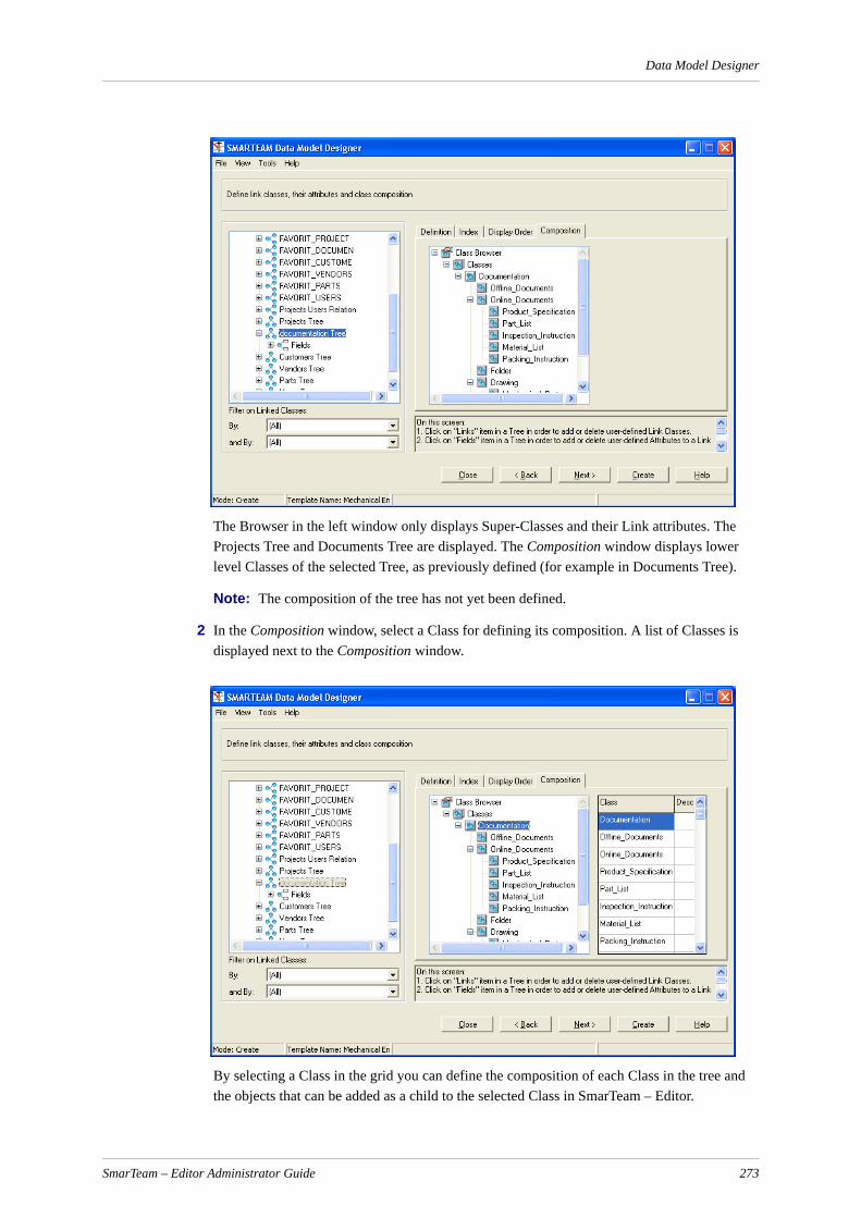
Data Model Designer
The Browser in the left window only displays Super-Classes and their Link attributes. The Projects Tree and Documents Tree are displayed. The Composition window displays lower level Classes of the selected Tree, as previously defined (for example in Documents Tree).
Note: The composition of the tree has not yet been defined.
2 In the Composition window, select a Class for defining its composition. A list of Classes is displayed next to the Composition window.
By selecting a Class in the grid you can define the composition of each Class in the tree and the objects that can be added as a child to the selected Class in SmarTeam – Editor.
SmarTeam – Editor Administrator Guide 273

Data Model Designer
3 Select a Class in the grid and click to check a box of the grid to indicate that the Class will be a child of the previously selected Class (displayed to its left). In the following example, Folder was selected in the tree. A checkmark was placed next to each sub-Class. In SmarTeam, Folder, Off Line documents, On Line documents, Drawing, Technical Specification and Document can be added as a Folder.
In the above example, Drawing was selected in a tree. A checkmark was placed next to the Drawing box in the grid. In SmarTeam, only another Drawing can be added as a child of a Drawing.
SmarTeam – Editor Administrator Guide 274

Data Model Designer
In the following example, Document was selected in the tree. No checkmarks were placed in the grid. In SmarTeam, no children can be added to a Document.
To define the composition of a Class:
1 Click to place a checkmark in the box.
2 Click again to remove the checkmark.
3 A red checkmark appears automatically when a sub-Class is automatically added as a child to the Composition tree. It cannot be removed because it indicates an inherited child.
4 Click Next to proceed to the following window.
This window enables you to design a form that is the layout for the Profile Card.
Working with an Integration in SmarTeam – EditorThis section describes how the Data Model Designer handles class compositions with an integration.
Consider the following scenario: In the Class Composition tab of the Data Model Designer, the user selects several classes and then deletes them. If a particular class composition is used by the integration, SmarTeam will not delete that class. A class composition selected for deletion will only be deleted if it is not used by the integration.
Creating and Modifying a FormAfter the setup is complete, each Class has its own Profile Card in the Data Model Designer that provides a default layout (Auto Form) for the Profile Card, which you can then modify. You can create and modify this form for each Class and sub-Class in a template. SmarTeam enables you to define the page tabs and fields to appear in the form, as well as modify the color, font and overall style of the form.
SmarTeam – Editor Administrator Guide 275

Data Model Designer
Note: Many of the design options are similar to those options used with the Form Designer option in SmarTeam. The Form Designer option is described in Form Designer.
This section provides instructions for:
Viewing a Form
Adding, Deleting and Re-ordering the Tabs
Specifying Attributes for Each Tab Page
Modifying the Color, Font and Alignment of a Label or Field
Selecting the Style Format for the Form
Creating a Profile Card
Viewing a Form
To view a form:
1 Click on a Class in the template to display its form.
The Auto Form is generated according to default guidelines as defined in the Wizard Options window.
The Profile Card window, selected from the Data Model Designer main menu, Tools, sub-menu Options, allows you to define exactly how many fields appear on a page and whether to create Tabs based on functionality, as shown below. (For an explanation of the Profile Card window, refer to The Data Model Designer Menu Bar.)
The default Auto Form displays a maximum of 10 fields in each page with only one tab, Attributes. If you have more than 10 Attributes, the Auto Form displays additional Tabs called Attributes1, Attributes2 and so on.
If you checked the By Functionality check box in the Wizard Options window, the Auto Form displays a File tab and/or a Revision tab depending on whether this Class was previously defined with File Control or Revision Control options. The File and Revision tabs display their respective fields.
Note: If you change the definitions in the Wizard Options window, you must click Modify… and select Auto Form to regenerate the Auto Form according to the newly defined guidelines.
You can now customize the form by changing the Tab names, and Attributes in each tab page as well as the general design of the pages.
IMPORTANT! If you do not want to modify the form and you have finished defining your template, you can proceed to generate the SmarTeam database structure. Click the Create button and SmarTeam will automatically create a database structure based on the template, as described in Creating a SmarTeam Database Structure.
2 Click the Modify button to display the Choices Dialog window. The Data Model Designer provides the following design options:
Form Wizard: Provides a series of windows in which you can design the form. Operating instructions are provided below.
SmarTeam – Editor Administrator Guide 276

Data Model Designer
Form Designer: Displays the Form Designer menu bar and window. Selecting the Form Designer utility or the Form Designer option in SmarTeam – Editor, can also access this window. Refer to Form Designer for operating instructions.
Auto Form: Displays the automatic default layout as previously defined in the Wizard Options window. If you have changed the definitions in the Wizard Options window, you must select Auto Form in order to regenerate the Auto Form according to the newly-defined guidelines.
3 To modify the form, select Form Wizard then click OK.
Adding, Deleting and Re-ordering the Tabs
After you select Form Wizard from the Choices Dialog window, the following window is displayed where you can add, delete and re-order the Tabs that will appear at the bottom of the Profile Card.
The following fields are displayed in this window:
Tabs: Tabs that will appear in the Profile Card.
Sample tabs: Tabs that are not currently displayed in the Profile Card.
Enter Your Own: To add a new Tab name, type a tab name in this field and then click the Add button. The Tab name will appear in the Tab box on the left.
To move Tabs between these fields:
1 Use the Arrow buttons between the fields.
2 Use the arrows below the Tabs box to determine the order of the Tabs to be displayed in the Profile Card.
3 Click Next to proceed to the next Form Wizard window and specify the Attributes for each Tab page.
Specifying Attributes for Each Tab Page
To specify attributes:
1 Click on a Tab to display the Attributes of that Tab page. The Attributes fields box lists the Attributes that will be displayed in the Profile Card. The Sample attributes box lists the Attributes that will not be displayed in the Profile Card.
2 Use the arrow buttons between the fields to move Attributes between these fields. For example, you can move the Creation_Date and CN_Department Attributes to the Sample attributes box, thereby removing them from this page of the Profile Card.
a Click on an Attribute to select it.
b Click the appropriate arrow button to move the Attribute to the Sample attributes box.
3 Click Next to proceed to the next Form Wizard window.
Modifying the Color, Font and Alignment of a Label or Field
A Label is the fixed text that appears in a Profile Card.
A Field is the entry box in which the user enters data in the Profile Card.
SmarTeam – Editor Administrator Guide 277
Data Model Designer
To modify labels:
1 Click the Label tab to display the next SmarTeam Form Wizard window.
To modify the color: In the Field Style area, click the Modify Color button to display a color selection window. Select a color and click OK.
To modify the font: In the Field Style area, click the Modify Font button to display a font selection window. Select a font and click OK.
To modify alignment: In the Field Style area, click the arrow to the right of the Alignment field to display a drop-down list of options and select one.
To modify the style: In the Label Style area, click one of the option buttons to design the style:
Raised: Gives the label a 3D appearance.
Flat: The labels have a standard appearance.
2 To modify the fields in the Profile Card, click the Fields tab to display the following window. In this window, you can modify the color and font of the fields in the Profile Card.
3 Click Next to proceed to the next Form Wizard window and select the style format for your form.
Selecting the Style Format for the Form
To select the style format:
1 Form Style: Click one of the radio buttons to specify whether the Fields will be distributed horizontally or vertically on the Profile Card.
Label Position: Click one of the radio buttons to select if the Labels will appear on top of a Field or to the side of a Field.
Form Size in Pixels: Adjust the form's size in pixels by entering a value for both width and height.
2 Click Next to proceed to the next Form Wizard window to preview the form layout and create the Profile Card.
Profile CardsThe SmarTeam Profile Card provides an organized interface that displays the attributes of a selected object.
Each Profile Card in SmarTeam – Editor is custom-designed to display relevant information about the object type. Therefore, each object type has its own Profile Card. For example, Documents, Materials and Items each have a different Profile Card.
In the Profile Card, you can view:
General information about the object, including its ID number.
Information about the file this object represents (when relevant).
Information about the object's revisions (when relevant).
The Profile Card can be displayed in two additional modes, Add or Update:
SmarTeam – Editor Administrator Guide 278
Data Model Designer
Add ModeDisplayed when you add a new object to SmarTeam – Editor. A new Profile Card is displayed with the word Add shown in the bottom, left corner. Information can be entered in the displayed fields.
Update ModeDisplayed when modifying attributes of an existing object. The Profile Card is displayed with the word Update shown in the bottom, left corner. You can also modify previously entered information and/or enter new information in the displayed fields.
A field is displayed in blue representing the object's ID number for each Profile Card. As defined during setup, the ID field in the Profile Card is displayed in blue to emphasize the importance of this field, as it represents the unique number for the selected object. This field might be filled in automatically, if defined as such during setup by the System Administrator, and can be modified by the user.
During setup, the Profile Card may be designed (via the SmarTeam Data Model Designer) with different tabs at the bottom of the page that display different sub-pages of information. These sub-pages may be organized according to functionality. If the object represents a file, there will be a File tab that opens a File page displaying various file fields. If the object has lifecycle management capabilities, there will be a Revisions page displaying various revision fields.
The following displays examples of fields that may appear in the Profile Card:
Note: These fields differ for different objects in the project while the general function-ality of the page and the kinds of fields remain the same.
Field (Fixed Text) Type Comment
ID Text entry Enter a number only. SmarTeam sometimes displays this field automatically.
Revision Text entry SmarTeam – Editor enters this field automatically.
State Text entry. Vault state. SmarTeam – Editor displays this field automatically.
Description Text entry Enter any text.
File Name File browser Click the Browser button to display a standard file selection window and select a file.
Directory Automatic The Directory path is automatically entered after a file is selected. You can click the Browser button to select a different directory.
File Type Predefined List
Click the arrow button to display a list and select an item.
Creation Date Date browser Click the Date button to display a date browser.
SmarTeam – Editor Administrator Guide 279

Data Model Designer
Creating a Profile Card
You can view the layout you designed in all the previous steps, as described below.
At this stage, you can click on the Prev button to return to previous windows to make further changes.
To create a Profile Card:
1 Click the Create button to create the Profile Card according to the layout shown in the window.
The Data Model Designer now returns to the first Form Wizard window.
2 At this stage in designing your Profile Card you can select one of the following:
Click Prev to return to previous Form Wizard windows to make further modifications on this form or modify other forms.
Save the template using the Save Template or Save Template As… options from the Data Model Designer main menu, sub-menu File.
From the Data Model Designer main menu, select File, Exit to exit the Data Model Designer without saving your changes.
Click Create to create a database based on this template.
Updating a Profile Card
Information describing an existing object in SmarTeam – Editor can be modified in the Profile Card. (When you update the Profile Card you are not updating the actual file attached to this object.)
To update a Profile Card:
1 In the selected Tree Browser, select the object you want to modify. The Profile Card for the selected object is automatically displayed in the right pane.
2 Right click to display a popup menu then click Update.
3 The Profile Card is then displayed in Update mode and previously entered definitions are displayed. You can add new details or modify existing information in the Profile Card.
4 If necessary, click on the individual page tabs at the bottom of the Profile Card to open different sub-pages in the Profile Card to update them.
5 Click OK to save any changes made - or click Cancel to abort any changes - and exit Update mode.
Creating a SmarTeam Database StructureAfter you have completed defining your template, click the Create button to generate a database structure based on this template. When you next start SmarTeam – Editor you can work with this newly created database.
You can now work with this database in SmarTeam – Editor, as follows:
6 From the SmarTeam – Editor main menu select File, Switch to Database to open the Database List window. The newly created database will appear in the Database List window.
7 Select and highlight the database then click OK.
SmarTeam – Editor Administrator Guide 280
Data Model Designer
Multi-language SupportThis function allows you to perform the following actions when working in the Data Model Designer:
The ability to use a different language interface in the Data Model Designer
Multi language support in the destination database
The Data Model Designer allows you to change the display language while working in the Data Model Designer.
To change the display language:
1 Select Tools, Language Selection from the Data Model Designer main menu.
2 Select the specific language.
The Data Model Designer takes the language definition from the source WizSrc database. The SmarTeam Translation Utility enables you to change the displayed language for all windows in the SmarTeam – Editor interface and save it to a destination database.
To add a new language to the Data Model Designer, or change the definitions for an existing language:
1 Use the Multi Language Utility to create/modify language definitions. Save all definitions in a destination database.
2 In the SmarTeam Wizard utility, from the main menu, select Tools, Destination Database to display the Select Alias window. Select the destination database created and saved in the previous step. (Refer to Destination Database for details about creating a database alias.)
3 In the Data Model Designer utility, from the main menu, select Tools, Multi Language List to display the SmarTeam Login window.
4 In the SmarTeam Login window, enter your login User name and Password, if necessary then click OK. After successful login, the Supported Languages window appears.
In the Supported Languages window, you can perform the following actions:
Copy language definitions from a source database in WizSrc format to a destination database in WizDst format and vice versa.
Update existing languages in a WizSrc database using the language in the destination database as a source and vice versa.
Move a language from the destination database.
Delete a language from the destination database.
IMPORTANT! This feature works differently to the Data Model Designer. When you use the Supported Languages feature, all changes are carried out immediately. All other changes in the destination database using the Data Model Designer utility are only carried out after clicking the Create button.
5 To copy a language from the source database to the destination database, select the language from the Source DB list in the left pane and click Copy. The selected language is copied to the right pane and appears in the Destination DB pane.
SmarTeam – Editor Administrator Guide 281

Data Model Designer
6 To move a language from the destination database to the source database, select the language from the Destination DB list in the left pane and click Move. The selected language is moved to the left pane and appears in the Source DB pane. This operation will delete the selected language from the destination database.
7 In addition to using the Copy and Move buttons, you can use the following buttons when updating a language in the Source DB or Destination DB:
Update: Use this button to update language definitions in the target database – corresponding definitions will be updated.
Overwrite: As for Update, with the addition that the language definitions from the updating database will override corresponding ones in the target database. The definitions in the updated database that do not have corresponding definitions in the updating one remain unchanged.
Replace: Language definitions in the target database will be replaced by the language definitions from the updating database.
IMPORTANT! When you select Replace, all previous language definitions in the target database will be overwritten.
The Data Model Designer Menu BarThe Data Model Designer menu bar provides various options for loading, saving, defining and viewing a template.
File Menu
The File menu provides options for loading and saving a template.
New TemplateStarts a new template that is not based on one of the SmarTeam templates.
Modify Template AttributesDisplays the Modify window.
The Modify window allows you to enter or modify the description of the selected template that appears in the right side of the window.
8 In the List of Templates pane, select a template to display its description in the Description pane (if a description exists for the selected template).
9 In the Description pane, modify an existing description or type in a new description; whichever is applicable for the selected template.
10 Click Set Icon… to select an applicable icon from the Icon Browser window to display for this template. Refer to the SmarTeam – Editor Online Help for details about the Icon Browser.
Load TemplateLoads a previously defined template into the Data Model Designer.
Load External Template /Import Template from DatabaseThe Load External Template option enables you to import a template from a file in WizSrc format.
SmarTeam – Editor Administrator Guide 282

Data Model Designer
The Import Template from Database option enables you to import a template from a file in WizDst format.
Modify Database StructureLoads the definitions of a working database structure into the Data Model Designer. You can modify definitions by adding new Classes and Attributes, changing the displayed name of a Class or Attribute, or re-defining an Attribute.
IMPORTANT! Changes to the basic structure of this template will result in loss of data. For example, if you delete a Class or an Attribute, the corresponding values will be lost.
It is recommended that you are very careful when modifying the Type field of an Attribute displayed in the Definition window. Changes to the Type field can inadvertently result in loss of data. For example, if you change the Type of an Attribute from Integer to Char, this can result in loss of data. If you change the Size of a field from 30 to 20, this also can result in loss of data.
Save TemplateSaves changes made to the selected template.
Save Template As . . .Saves the loaded template under a new name. You can use this option to copy an existing template, modify it and save it under a new name, creating a new template without overwriting the previous template.
Delete TemplateDeletes a template from the list of templates.
Exit Quits the Data Model Designer.
View Menu
The View menu provides different options for displaying the selected template.
Class NameThis option is displayed by default. The Class names are displayed in the template and in the tree browsers in SmarTeam – Editor.
Table NameDisplays the Table Name for each Class.
The object name is displayed in the form that an external application would access it, such as Report Writer. The Table Name is preceded by the prefix TN_ if the Table Name with Prefix option from the Options menu is checked.
Field NameDisplays the Field (Attributes) names in upper case letters with an underscore to replace spaces between words. This is the name automatically assigned by SmarTeam to a field.
Field DisplayShows the name of the Fields (Attributes) exactly as they are displayed in the Profile Card. Refer to Defining Indexes and Class Attributes.
SmarTeam – Editor Administrator Guide 283

Data Model Designer
Tools Menu
The Tools menu provides various default conditions that can be selected or unselected.
OptionsSelect Options to set specific Data Model Designer default options via the General and Profile Card tab pages.
General Tab Page
Display warningsCheck this option to specify that more detailed error messages are displayed (recommended). The following is an example of a situation, which causes a detailed warning message:
If you delete the Class, Engines, which has sub-Classes, Diesel and Electric, a detailed warning message is displayed notifying you that its sub-Classes will also be deleted.
Automatically add prefix to table names SmarTeam automatically places a prefix before each Table name. These prefixes ensure that the names assigned to a Class Table are unique to a specific database and are not reserved (names that are used in SmarTeam's internal database structure). It is recommended that you enable this option.Automatically add prefix to column names SmarTeam automatically places a prefix before each Attribute name (Column name). These prefixes ensure that the names assigned to an Attribute are unique to a specific database and are not reserved (names that are used in SmarTeam's internal database structure). It is recommended that you enable this option.Assign default values to internal attributesCheck this option to select your own values for file and directory names. The minimum value is no less than 12 and the maximum value is 256.Profile Card Tab PageTabsThis area contains two fields. Attributes per tab - Specify how many fields will appear in each page of the Profile Card (with a maximum of 10)By Functionality check box - Specify whether the Profile Card will be organized into different Tab pages according to functionality. The Auto Form, which is the default layout of the Profile Card in the Data Model Designer, displays the Tabs according to definitions selected in the Wizard Options window. You can change the Tab names and the fields in each Tab page if you select to customize the form.
SmarTeam – Editor Administrator Guide 284
Data Model Designer
If you select to organize the Auto Form (and subsequently the Profile Card) into different tab pages (by selecting the By Functionality check box), the Data Model Designer will automatically create different tabs based on the defined functionality of a Class. If a Class has File and/or Revision control options the Profile Card will automatically have the following Tabs:
Attributes (by default), displaying general attributes
File, displaying File control Attributes, such as File Name and File Type, and/or
Revisions, displaying Revision control options, such as Revision and Effectivity From.
If you do not select the By Functionality check box, then all the fields are placed in the Attributes page. If there are more fields than the number defined in the Fields per tab field of the Wizard Options window, SmarTeam automatically creates more Tab pages labeled Attributes1, Attributes2 and so on.FontsThis area contains three fields:
Label controls - Set the font for the label controls
Other controls - Set the font for other controls
Force using Ms Shell DLG - Force the newly created controls using MS Shell DLG
Lookup Tables
This option enables you to add/delete a Lookup Table name to/from the list of Lookup Tables. A Lookup Table is a dropdown list that appears in the Profile Card for a specific field, such as File Type.
When you define a Class Attribute, you can assign one of these Lookup Tables to the Attribute, making the Attribute a dropdown list in the Profile Card.
Remember that you can only add and delete names of Lookup Tables in the Lookup Tables window which opens when you select this option. The values (or options) that will later appear in the dropdown list of the Profile Card are defined in SmarTeam using the Lookup Tables option from the Data Model Designer Options menu. Refer to Defining the Values of a Lookup Table for further details.
To add a new name to the Lookup List:
Type a new name in the Enter your own field and click the Add button, or select a name from the Sample Entities box on the right and move it to the Recommendation box using the appropriate arrow button.
To remove a name from the Lookup list:
Select the name in the Recommendation box on the left and move it to the Sample Entities box using the right pointing arrow buttons or click the Delete button.
Note: You can also display the above window when you are assigning a Lookup Table to an Attribute.
Internal Classes
Select this option to view the internal classes of the selected template. Click on a field to view its description (and Index).
SmarTeam – Editor Administrator Guide 285

Data Model Designer
Note: Most of the text in the fields appears in gray. These fields cannot be changed as they were defined in previous steps. In this window, only descriptive fields such as Display and Description can be changed in order to change the displayed view in the Profile Card.
Language Selection
Select this option to change the displayed language for the Data Model Designer as previously defined in the Supported Languages window.
From the drop-down list, select the language you want to display.
Destination Database – WizDst
Displays the currently selected destination database for building your SmarTeam database structure. The default destination database is Wizdst, which is an MSDE database installed optionally during the SmarTeam installation process
To create your SmarTeam database other than in the default database, you will first need to create a new database alias to direct the Data Model Designer to the selected database. Refer to Database Connection Manager for further instructions.
Note: Upon installing SmarTeam, the default password for SmarTeam databases is SMARTDBUSER.
After Running the Data Model DesignerAfter running the Data Model Designer for an integration, the administrator must enter the Integration Tools Setup and set up the default classes for this integration.
After running Data Model Designer, you need to restart the Microsoft Internet Information Services (IIS) on SmarTeam WEB servers (Web Editor and 3DLive).
To restart the server:
1 From the Web Server taskbar Start button, select Run.
2 Type IISReset then click OK. This stops and then restarts the Internet Information Service (IIS).
The Multi-site Data Model WizardThe Multi-site Data Model Wizard utility lets you add or remove Multi-site data model mechanisms and change Multi-site options without using the generic SmarTeam – Data Model Designer application.
Launching the Multi-site Data Model Wizard
To launch the Multi-site Data Model Wizard:
Double click the file MultisiteDataModelWizard.exe located in the <SmarTeam>\Bin direc-tory to launch the Multi-site Data Model Wizard utility.
SmarTeam – Editor Administrator Guide 286
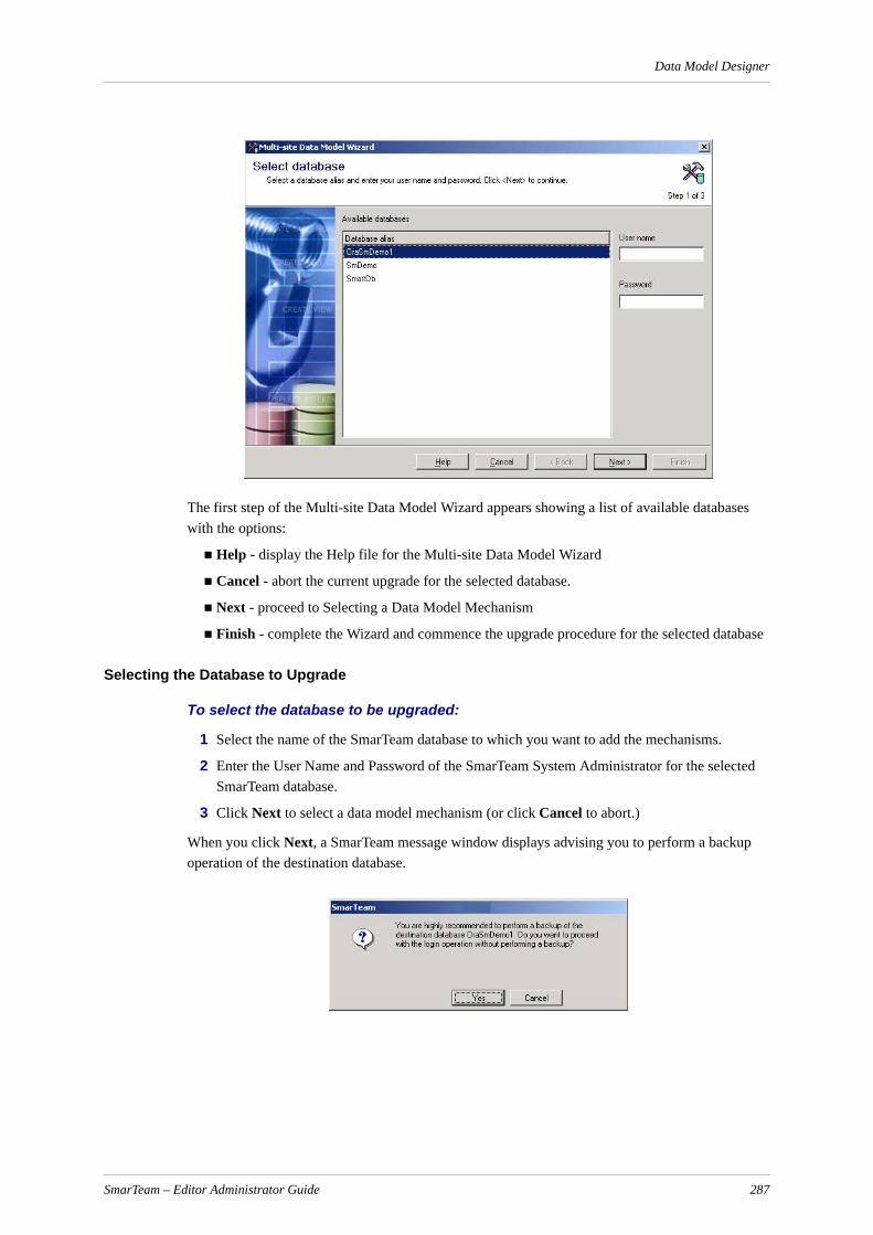
Data Model Designer
The first step of the Multi-site Data Model Wizard appears showing a list of available databases with the options:
Help - display the Help file for the Multi-site Data Model Wizard
Cancel - abort the current upgrade for the selected database.
Next - proceed to Selecting a Data Model Mechanism
Finish - complete the Wizard and commence the upgrade procedure for the selected database
Selecting the Database to Upgrade
To select the database to be upgraded:
1 Select the name of the SmarTeam database to which you want to add the mechanisms.
2 Enter the User Name and Password of the SmarTeam System Administrator for the selected SmarTeam database.
3 Click Next to select a data model mechanism (or click Cancel to abort.)
When you click Next, a SmarTeam message window displays advising you to perform a backup operation of the destination database.
SmarTeam – Editor Administrator Guide 287

Data Model Designer
If you have already performed a backup, click Yes to proceed to the next step, otherwise click Cancel to abort the Multi-site Data Model Wizard and perform a backup operation of the selected database.
After backing up the selected database, run the Multi-site Data Model Wizard again to perform the required database changes.
Selecting Data Model Mechanisms
This section describes how to add the following Multi-site data model mechanisms:
Distributed mechanism responsible for the database replication
Vault Replication
The Data Model Mechanisms window appears showing the possible Data Model replication mechanisms to install:
4 Select the name of the SmarTeam database to which you want to add the mechanisms.
Note: It is recommended to select both mechanisms.
From this window the following options are available:
Help - display the Help file for the Multi-site Data Model Wizard
Cancel - abort the current upgrade for the selected database.
Next - proceed to Setting Multi-site Options
Finish - complete the Wizard and commence the upgrade procedure for the selected database
Setting Multi-site Options
To set the multi-site options in the Multi-site Options window:
1 Select one or both Multi-site Options as shown below:
SmarTeam – Editor Administrator Guide 288

Data Model Designer
Note: It is recommended to check both options.
2 Click Next to commence updating the selected database with the selected mechanism(s) and option(s) or click Cancel to abort the process and not to update the selected database.
The Multi-site Data Model Wizard upgrades and displays all changes to the selected database.
Note: This process will take a few minutes, depending on the size of the selected database.
At the end of the process, a SmarTeam information message appears, informing that the database was successfully updated.
3 Click OK to continue.
4 In the Multi-site Data Model Wizard, if necessary, use the scroll bar to view the changes made to the selected database. This completes upgrading the selected database with Multi-site functionality.
5 Click Close to exit the Multi-site Data Model Wizard.
SmarTeam – Editor Administrator Guide 289

Form Designer
Form DesignerThe Form Designer utility allows you to modify an existing Profile Card or create a new one. You can also modify the Single Object View that displays the desktop with one document (object) instead of a tree browser. This view is often used for a Quick Find (see SmarTeam Quick Find for details).
Note: The system administrator generally performs this function.
The following illustration displays a sample Profile Card as displayed in SmarTeam – Editor.
The following illustration displays a sample Profile Card as displayed in Single Object View in SmarTeam – Editor.
SmarTeam – Editor Administrator Guide 290
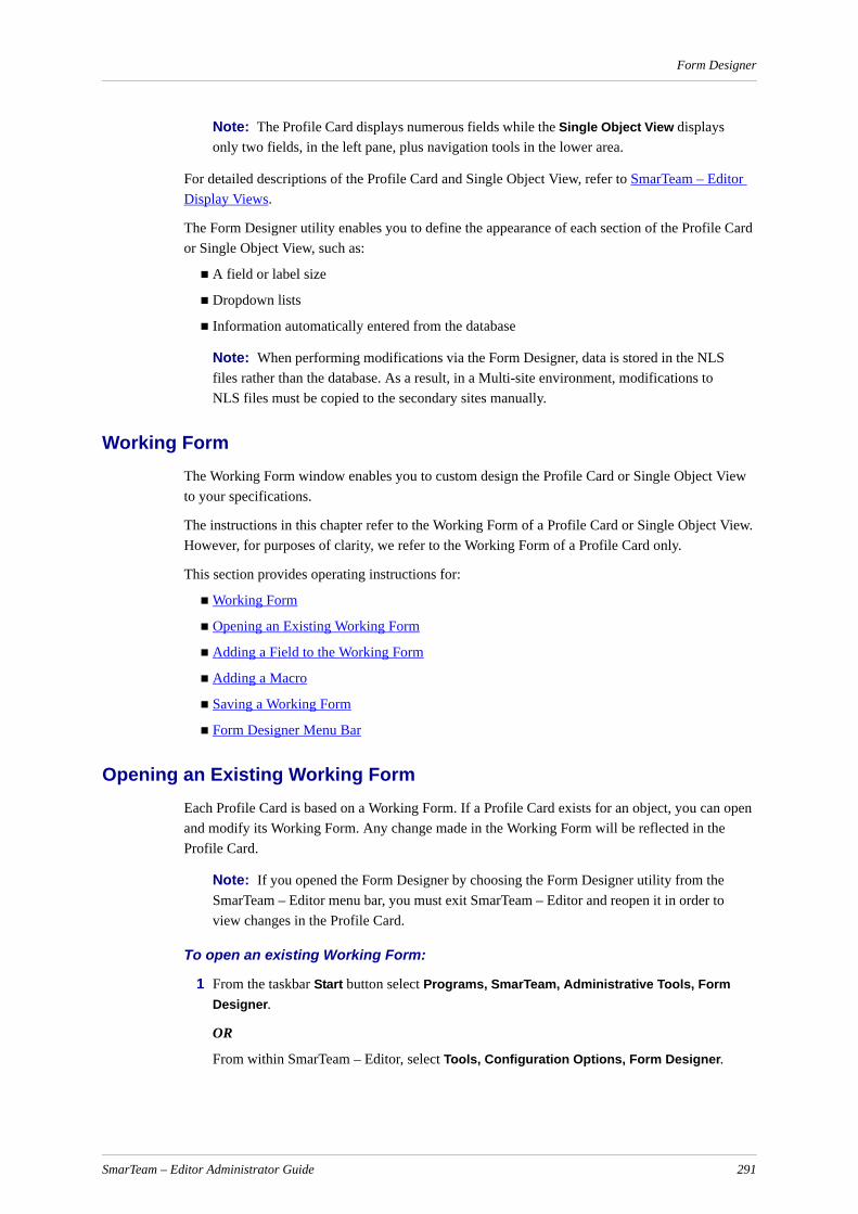
Form Designer
Note: The Profile Card displays numerous fields while the Single Object View displays only two fields, in the left pane, plus navigation tools in the lower area.
For detailed descriptions of the Profile Card and Single Object View, refer to SmarTeam – Editor Display Views.
The Form Designer utility enables you to define the appearance of each section of the Profile Card or Single Object View, such as:
A field or label size
Dropdown lists
Information automatically entered from the database
Note: When performing modifications via the Form Designer, data is stored in the NLS files rather than the database. As a result, in a Multi-site environment, modifications to NLS files must be copied to the secondary sites manually.
Working FormThe Working Form window enables you to custom design the Profile Card or Single Object View to your specifications.
The instructions in this chapter refer to the Working Form of a Profile Card or Single Object View. However, for purposes of clarity, we refer to the Working Form of a Profile Card only.
This section provides operating instructions for:
Working Form
Opening an Existing Working Form
Adding a Field to the Working Form
Adding a Macro
Saving a Working Form
Form Designer Menu Bar
Opening an Existing Working FormEach Profile Card is based on a Working Form. If a Profile Card exists for an object, you can open and modify its Working Form. Any change made in the Working Form will be reflected in the Profile Card.
Note: If you opened the Form Designer by choosing the Form Designer utility from the SmarTeam – Editor menu bar, you must exit SmarTeam – Editor and reopen it in order to view changes in the Profile Card.
To open an existing Working Form:
1 From the taskbar Start button select Programs, SmarTeam, Administrative Tools, Form Designer.
OR
From within SmarTeam – Editor, select Tools, Configuration Options, Form Designer.
SmarTeam – Editor Administrator Guide 291

Form Designer
2 The SmarTeam User Login window opens. Enter your User name and Password, if necessary then click OK for your entries to be accepted and to close the window.
3 After successful login, the Open Profile Card window opens.
From the Open Profile Card window you can access two forms that can be modified for each Class, as follows:
Attribute Profile Card: Displays a Working Form of the Profile Card for the selected Class.
Single Object Form: Displays a Working Form of the Single Object View for the selected Class.
4 In the Open Profile Card window select a Class. Select either the Attribute Profile Card or Single Object Form then click OK. Your selection opens and the Form Designer toolbar appears.
If you selected Single Object Form, the window displays the Single Object View.
By default, the Single Object Working Form displays two default fields, ID and Revision, for the selected Class. If required, you can add more fields to the Single Object Working Form.
If you selected Attribute Profile Card, the Working Form window displays the selected Profile Card. This window displays different kinds of fields and labels as previously designed using the Form Designer utility.
SmarTeam – Editor Administrator Guide 292

Form Designer
Note: A list of the different types of fields that can be added or modified in the Working Form is shown below. When you click on a button in the Form Designer toolbar then click in the Working Form, the applicable field is displayed.
Tool Description Displayed in Working Form
Label Displays a label in the Working Form.
TextEdit Links a field to the database. Information from the database is automatically displayed in the Working Form.
Memo Displays a notes area in the Working Form.
Note: A memo field cannot be justified to the right.
ComboBox/ Lookup
Displays a dropdown list in the Working Form. The dropdown lists are defined by choosing the Lookup Tables option from the Tools menu in the SmarTeam – Editor main menu. Refer to Creating a Lookup Field.
Multi-Combo Box/ Reference to Class
Inserts a Reference field in the Profile Card, and defines which attributes of the referenced Class will be displayed. Refer to Creating a Multi-combo (Reference) Field.
Panel Displays a 3D area is in the Working Form that can be used as the background for other fields to group them visually. It can also be used as a separator box.
Checkbox Places a checkbox in the Working Form to display a Yes/No value.
Radio Group/ Lookup
Displays a radio group and dropdown list in the Working Form. Radio buttons can be added in rows and columns. The dropdown lists are defined by choosing the Lookup Tables option from the Tools menu in the SmarTeam – Editor main menu. Refer to Creating a Lookup Field.
Reference to Class Quick Find
Opens a Quick Find dialog from the Reference to Class field. Refer to SmarTeam Quick Find.
Button Displays a button in the Working Form.
Image Inserts an icon on the Profile Card. An Icon Browser is displayed. Select an icon and click OK.
Viewer Inserts a thumbnail representation of the associated Drawing. The source for the thumbnail is the file listed in the File Info page of the Profile Card.
Date Edit Displays a date selection field. In the Profile Card, the user can select a date for this field.
Date Time Edit
Displays a date and time selection field. In the Profile Card, the user can select a date and time for this field.
SmarTeam – Editor Administrator Guide 293

Form Designer
Note: You cannot define a label or image at the top of a panel.
Adding a Field to the Working FormYou can add fields to a new Working Form or to a previously defined working form using the Form Designer toolbar. The Form Designer utility consists of two toolbars, Standard or Palette.
Standard Toolbar
Palette Toolbar
To add a field to the Working Form:
1 Select a tool from the toolbar.
2 Click and drag the mouse in the Working Form to define the location and size of the field.
Relative Time
Shows the relative time of a flow process between two points in time. The relative time is calculated by applying a user-defined script.
File Browser Displays a file selection field. In the Profile Card, the user can select a file from a standard selection window.
Directory Browser
Displays a directory selection field. In the Profile Card, the user can select a directory from a standard selection window.
Hyperlink Places a URL field in the Profile Card to create a hyperlink to a selected URL. When the URL is selected, the appropriate Web page will open in the default Web browser.
HTML Browser
Places an HTML browser field in the Profile Card. When SmarTeam – Editor displays the selected object, the Web page will automatically be displayed in the Profile Card.
Tool Description Displayed in Working Form
SmarTeam – Editor Administrator Guide 294

Form Designer
The field is displayed in the Working Form and the field's Properties window is displayed to the left.
SmarTeam – Editor automatically names the selected field, for example Label1, Panel3, TextEdit2, by adding a number incremented by 1 to the field type. This name is displayed in the field on the Working Form and in the Properties window.
3 In the Properties window, you can modify the selected field's default properties. Refer to Modifying the Properties of a Field for details.
Note: To redisplay the Properties window, select the field, then from the Form Designer main menu select View, sub-menu Properties.
4 In the Form Designer toolbar click on the Save button to save your changes in the Profile Card, or from the Form Designer main menu select File, sub-menu Save.
Notes:
a In order to define a mandatory field for CATIA Web Integration you must set the field as Mandatory in the Data Model Designer. You cannot define a mandatory field for CATIA Web Integration in the Profile Card using the Form Designer or Web Form Designer.
b When initiating a process in SmarTeam – Editor, the system does not provide a warning if mandatory attributes on the process profile card are not filled in. The process is initiated but remains at the Initiator's node and does not move forward. Therefore, it is recom-mended that you define a script on the Before Send Accept for Start Node hook for the validation of the mandatory fields.
Modifying the Properties of a Field
When you create a new field or select a previously defined field, the Properties window for that field is displayed to the left of the Working Form. You can modify any of these properties.
SmarTeam – Editor Administrator Guide 295

Form Designer
When adding or updating controls in a Profile Card, the text is saved in the NLS and not in the database.
To modify the properties of a field:
1 Select and click on a field.
2 From the Form Designer main menu select View, sub-menu Properties to display the Properties window. This window lists all the properties of the selected field and you can then modify these properties.
Note: The Properties window is automatically displayed after creating a new field.
The following fields may appear in the Properties window:
Field Description
Title Automatically displays the field name. This is the first field in the Properties window. You can view the properties of a different field by choosing a new field name. Click the dropdown arrow to select from the available options; the Properties window now displays the properties of the selected field.
Caption Displays the text of a label or the name of the database (TextEdit) field.
Color Displays a number representing the color selected in the color selection window.
Column Displays the selected database field to be linked to the field selected in the form.
Font Displays the font as selected previously from the font selection window.
Height Displays the height of the field.
Hint Displays the status bar description (as shown in the bottom left corner) that is displayed when a user points to the field. You can enter a description of the functionality of the selected field. This text is displayed in the status bar.
Image File Displays the file path of the selected image.
Justification Indicates whether the field is right or left justified, or centered.
Left Displays the field's location in the Form.
Mask Name Displays the mask name (or formula) which generates the value of this field according to its incrementation formula. Refer to Assigning a Mask Name.
ReadOnly Displays True or False to indicate if this field is read-only (cannot be modified) in the Profile Card.
Required Displays True or False to indicate if this field must be completed in the Profile Card.
SmarTeam – Editor Administrator Guide 296

Form Designer
For a description of the tabs at the bottom of the Properties window, refer to the Events/Information Tabs.
3 In the Properties window, click in a field to modify it. The selected field becomes active, enabling you to enter new information in the field.
Some fields display an arrow after they are selected. Click on the field's arrow to display a dropdown list and select an option.
Other fields display a Selection button after they are selected. Click the Selection button to display a selection window to select a new property.
For example, in the font window, you can click the Selection button to display a standard font selection window. In the Font window, select an option then click OK.
Events/Information TabsThe Events tab, located at the bottom of the Properties window, allows you to add a script function (macro) to the Profile Card that is executed when the user clicks in or exits the associated field. For example, you can create a macro that will automatically generate a value for the Items Type field by concatenating other field values. When you click in the Items Type field of the Profile Card, a value is automatically displayed. Refer to Adding a Macro for further instructions.
The Information tab, located at the bottom of the Properties window, displays information about the selected field and cannot be modified.
TabOrder Indicates the order in which fields are selected in the Profile Card when the user presses the Tab key. The number entered in this field represents the field's location in the selection sequence. For example, if 2 is entered, this field will be selected after the user presses Tab twice. By default, the Tab Order is defined by the order in which the field is added to the Working Form.
Top The top left position on the Working Form.
Width Displays the width of the field in pixels.
Field Description
SmarTeam – Editor Administrator Guide 297

Form Designer
The Reference to Class field includes two types of controls. The first allows you to locate an object from a list. The second type enables you to locate the object using SmarTeam.
Adding or Modifying a TextEdit FieldA TextEdit field is a field that displays alphanumeric data from the SmarTeam database. When you open a Profile Card, the linked information from the database is automatically displayed in this field. For example, if the field Approval Date is created in a Working Form for a Drawing as a TextEdit field, the Drawing's Profile Card automatically displays a date (from the database) in the Approval Date field.
To create a TextEdit field:
1 Click on the TextEdit tool from the Form Designer toolbar.
2 Click and drag the mouse in the Working Form to define the location and size of the field. The Properties window is then displayed.
3 In the Properties window, click the Column field to display a list of database fields.
4 Select a database field.
5 When a user opens this Profile Card, information from the database will be displayed automatically in this TextEdit field. For example: The field Department is selected and its Properties window is displayed. If you then select CN_ID in the Column field of the Properties window, the Profile Card will automatically display an ID number (from the database) in the selected field.
Note: After modifying the Properties window, you must exit the SmarTeam application and reopen it in order to view changes in the Profile Card.
Modifying a LabelIf two labels contain the same text, changing one label text will also change the second label text.
To use two different texts, delete one of the labels and then recreate it.
SmarTeam – Editor Administrator Guide 298
Form Designer
Creating a Lookup Field
A lookup field appears in the Profile Card as a dropdown list, enabling the you to select a defined option.
To create a lookup field:
Define the values of a Lookup Table. The Lookup Tables option is accessed from the SmarTeam – Editor menu bar (not the Form Designer menu bar). Instructions for defining values for a Lookup Table are provided below.
Add a lookup field in the Working Form.Select a name for this field from the list of previously-defined Lookup Tables.For example: You can create a Lookup Table (using the Data Model Designer) named Phase and assign values for it such as Design, Development and Testing. In the Working Form, you can then create a lookup field and select File Type in the Lookup field of the Properties window. When a user clicks the arrow to the right of the File Type field in the Profile Card, a dropdown list is displayed with three options, Design, Development and Testing.
Defining the Values of a Lookup Table
A Lookup Table is a dropdown list of options which you can select. The Lookup Table names were previously defined during setup, as described in The Data Model Designer Menu Bar. Using the Lookup Tables option, you can define the values or options that appear in the dropdown lists.
The Lookup Table option is accessed from the SmarTeam – Editor main menu, sub-menu Tools.
Note: If the Form Designer utility is running, you will need to first exit before defining Lookup Table values. To exit the utility, from the Form Designer main menu select File, Exit. If you have not yet saved changes made to a Working Form, a message is displayed prompting you to save your changes.
After a Lookup Table and its values are defined, you can add it to a Profile Card by selecting the Lookup tool from the Form Designer toolbar as described in Creating a Lookup Field.
You can define values for a new Lookup Table or modify the options for a previously defined Lookup Table.
To define the values of a Lookup Table:
1 From the SmarTeam – Editor's main menu select Tools, Configuration Options, Lookup Tables to display the Lookup Table window. The Lookup Tables previously defined during setup are shown in the Tables list.
SmarTeam – Editor Administrator Guide 299
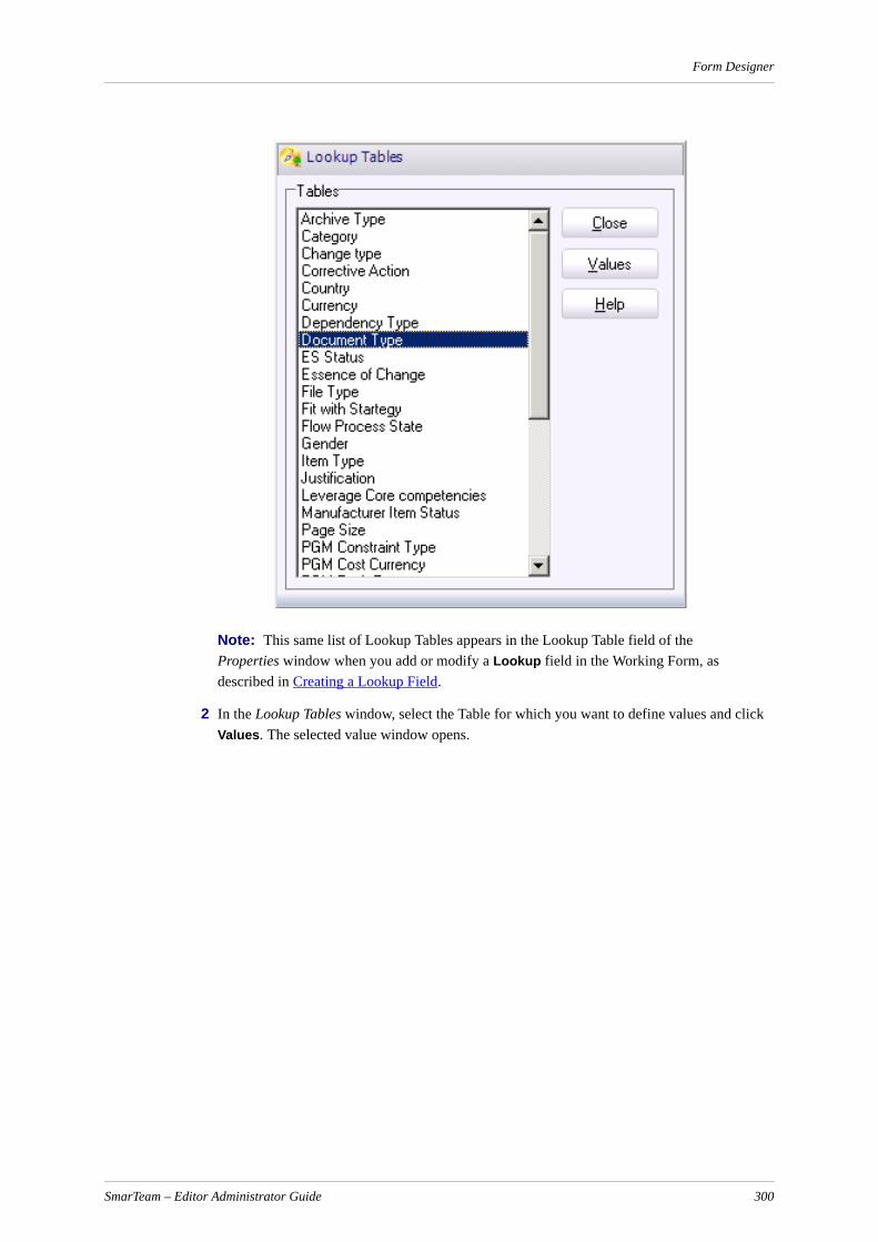
Form Designer
Note: This same list of Lookup Tables appears in the Lookup Table field of the Properties window when you add or modify a Lookup field in the Working Form, as described in Creating a Lookup Field.
2 In the Lookup Tables window, select the Table for which you want to define values and click Values. The selected value window opens.
SmarTeam – Editor Administrator Guide 300

Form Designer
In the new window, an administrator can:
Add new values, delete and modify previously defined values
Change the displayed order of the value names.
Sort the values with the buttons on the right side, ascending or descending
Each new value must be a new object name in SmarTeam – Editor.
To add a new value, select an existing value and click Modify. Change the values displayed in the Name and Description fields and then click Add. The new value is added to the list in the Description window.
To delete a value, select the value in the Description window, click Modify and then click Delete.
SmarTeam – Editor Administrator Guide 301

Form Designer
To modify a value, select the value in the Description window; the selected value appears in the Value field. Make your changes directly to the value displayed in the Value field and click Modify. The modified value replaces the previous value in the Description window.
To change the order displayed in the Description window, select a value and then click the Up or Down arrows as applicable to reposition your selection.
To view the default value predefined in the database, click Highlight Default.
3 Click Close to save your changes and return to the Lookup Tables window.
4 In the Lookup Tables window click Close to exit.
5 Proceed to Adding a Lookup Field in the Working Form.
Adding a Lookup Field in the Working Form
You can add or modify a Lookup field using the Working Form. When the Properties window is displayed, you can select the name of the Lookup Table that will be displayed in the Profile Card for this field.
To add a Lookup field:
1 Click on the Lookup tool from the Form Designer toolbar. Click and drag the mouse in the Working Form to define the location and size of the Lookup field. The Properties window is displayed.
2 In the Column field of the Properties window, select the database field to be linked to this field. The value selected by you for this field is stored in the appropriate Column of the database.
3 The selected database name appears in the Lookup Name field of the Properties window.
In the Profile Card, this field will display a dropdown list of options when the user clicks the arrow to the right of the field. You can then select one option from the list.
Adding an Internet Link to the Profile Card
The Form Designer enables an Internet link to easily be added to any Profile Card. This is done by adding one of the following field types:
A URL hyperlink field
An HTML Browser window
When a URL field is added to a Profile Card for a specific Class, clicking on the defined hyperlink will open the Internet link via the user's default browser.
When an HTML Browser window is added to a Profile Card for a specific Class, the defined Web page will automatically be displayed in the HTML window, when an object type (for that Class) is displayed.
To implement this feature, an attribute type must first be defined (e.g. URL) in the Data Model Designer. Refer to Defining Indexes and Class Attributes for details. In the Type field for the defined attribute, select URL.
To place a URL hyperlink field in a selected Profile Card:
1 From the Form Designer toolbar:
SmarTeam – Editor Administrator Guide 302

Form Designer
Click on the Hyperlink button to add a URL field and drag the cursor to the required size and location on the Working Form.
OR
Click on the HTML Browser button to add an HTML Browser field and drag the cursor to the required size and location on the Working Form.
2 When adding a URL field, in the displayed Properties window, click the Caption field and enter a name for the field (e.g., Hyperlink).
3 In the displayed Properties window, click the Column field and select the URL attribute. (This attribute should have previously been defined in the Data Model Designer.)
4 In the Form Designer select File, Save from the main menu to save your changes.
5 From the main menu, select File, Exit to exit the Form Designer utility.
When a user displays an object in SmarTeam – Editor with a URL field (e.g. Hyperlink), he/she can select the Update function and add a URL address to the URL field or an HTML Browser address to the HTML Browser field.
When you click on the hyperlink, the selected Web page will open in your default's HTML Browser.
When a URL address is added to an HTML Browser field, the selected Web page is displayed whenever the Profile Card is displayed in SmarTeam applications. The caption is not displayed in the HTML browser control on the Profile Card.
Creating a Multi-combo (Reference) Field
A Multi-Combo field appears in the Profile Card as a multi-column dropdown list. It serves as a visual reference to one object from another SmarTeam Class. The user can select one object from the referenced Class and display it in the Profile Card. For example, a Steel Profile Card may have a multi-column field for the Contacts Class.
SmarTeam – Editor Administrator Guide 303
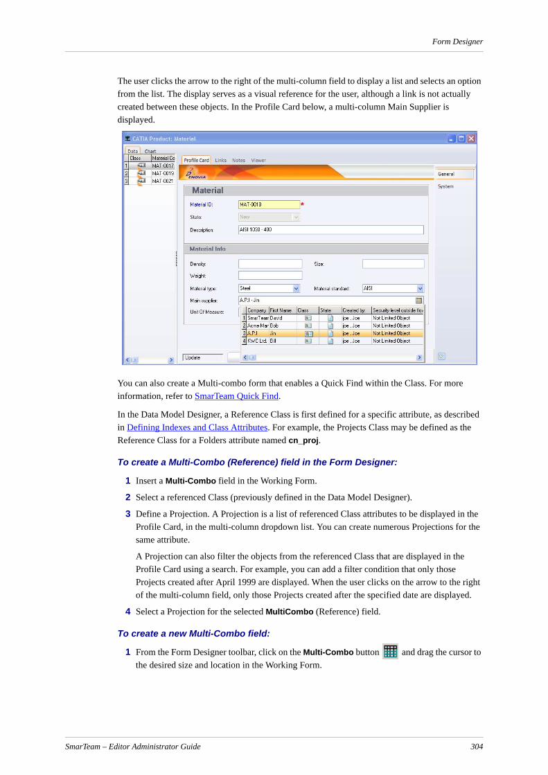
Form Designer
The user clicks the arrow to the right of the multi-column field to display a list and selects an option from the list. The display serves as a visual reference for the user, although a link is not actually created between these objects. In the Profile Card below, a multi-column Main Supplier is displayed.
You can also create a Multi-combo form that enables a Quick Find within the Class. For more information, refer to SmarTeam Quick Find.
In the Data Model Designer, a Reference Class is first defined for a specific attribute, as described in Defining Indexes and Class Attributes. For example, the Projects Class may be defined as the Reference Class for a Folders attribute named cn_proj.
To create a Multi-Combo (Reference) field in the Form Designer:
1 Insert a Multi-Combo field in the Working Form.
2 Select a referenced Class (previously defined in the Data Model Designer).
3 Define a Projection. A Projection is a list of referenced Class attributes to be displayed in the Profile Card, in the multi-column dropdown list. You can create numerous Projections for the same attribute.
A Projection can also filter the objects from the referenced Class that are displayed in the Profile Card using a search. For example, you can add a filter condition that only those Projects created after April 1999 are displayed. When the user clicks on the arrow to the right of the multi-column field, only those Projects created after the specified date are displayed.
4 Select a Projection for the selected MultiCombo (Reference) field.
To create a new Multi-Combo field:
1 From the Form Designer toolbar, click on the Multi-Combo button and drag the cursor to the desired size and location in the Working Form.
SmarTeam – Editor Administrator Guide 304

Form Designer
2 In the displayed Properties window, click the Column field and select a Reference Class attribute. (These attributes and their reference Classes were defined in the Data Model Designer.)
3 The RefClass field shows the name of the Class that was defined in the Data Model Designer as the Reference Class for the selected attribute.
4 Click the button to the right of the Projection Name field to display the Projection Selection window.
5 In the Projection Selection window, click Add to display the Projection Details window.
6 In the Projection Details window, define Projection Details for the selected Class as follows:
SmarTeam – Editor Administrator Guide 305
Form Designer
Class name: Displays the selected reference Class.
Projection name: Enter a suitable identifying name for the Projection. This name will be displayed in the Projection Selection window.
Query name: If you need to filter the displayed Reference Class, click the Selection button to display the Search Editor window. Select an existing search or create a new search, according to your requirements. Refer to Creating and Modifying Searches for information about using the SmarTeam – Editor Search tools.
For example, you can define or select a search of all Projects to filter Projects by their Creation Date. Only Projects created after their creation date will be displayed when the user clicks on the Reference field.
Note: The type of query specified in the Query Name field must match the Query class selected. If it does not, an error message appears.
Separator: Enter a separator to display between attributes, such as a comma or semi-colon, for example: PR31,Water Pump or PR31;Water Pump.
Attributes: Displays the Select Attributes – Class [Name] window to allow you to define referenced Class attributes to display in the Profile Card's multi-column field.
7 In the Projection Details window, click OK to save your changes, or click Cancel to abort any changes made, and return to the Projection Selection window. The Projection Selection window is redisplayed with the newly-defined Projection.
You can add or modify other Projections or select one from the list.
In the Projection Selection window select a Projection and click Select to assign the selected Projection to the MultiCombo field.
To modify a Projection in a Multi-Combo field:
1 In the selected Profile Card displayed in the Working Form, click the MultiCombo field that you want to modify. The selected field's Properties window is displayed to the left of the Working Form.
2 In the displayed Properties window, click the Projection Name field to activate it. Then, click on the Selection button to open the Projection Selection window.
3 In the Projection Selection window, click Modify to display the Projection Details window. The window is displayed with fields already defined. For an explanation of each field in the Projection Details window, refer to Creating a Multi-combo (Reference) Field.
4 Enter your changes as necessary, then click OK to save your changes or Cancel to abort any changes made and to return to the Projection Selection window.
5 In the Projection Selection window, click Select or Close for your changes to be applied to the selected Projection Name field.
To delete a Projection in a Multi-Combo field:
1 In the selected Profile Card displayed in the Working Form, click the Multi-Combo field whose Projection you want to delete. The selected field's Properties window is displayed to the left of the Working Form.
2 In the displayed Properties window, click the Projection Name field to activate it then click on the Selection button to open the Projection Selection window.
SmarTeam – Editor Administrator Guide 306
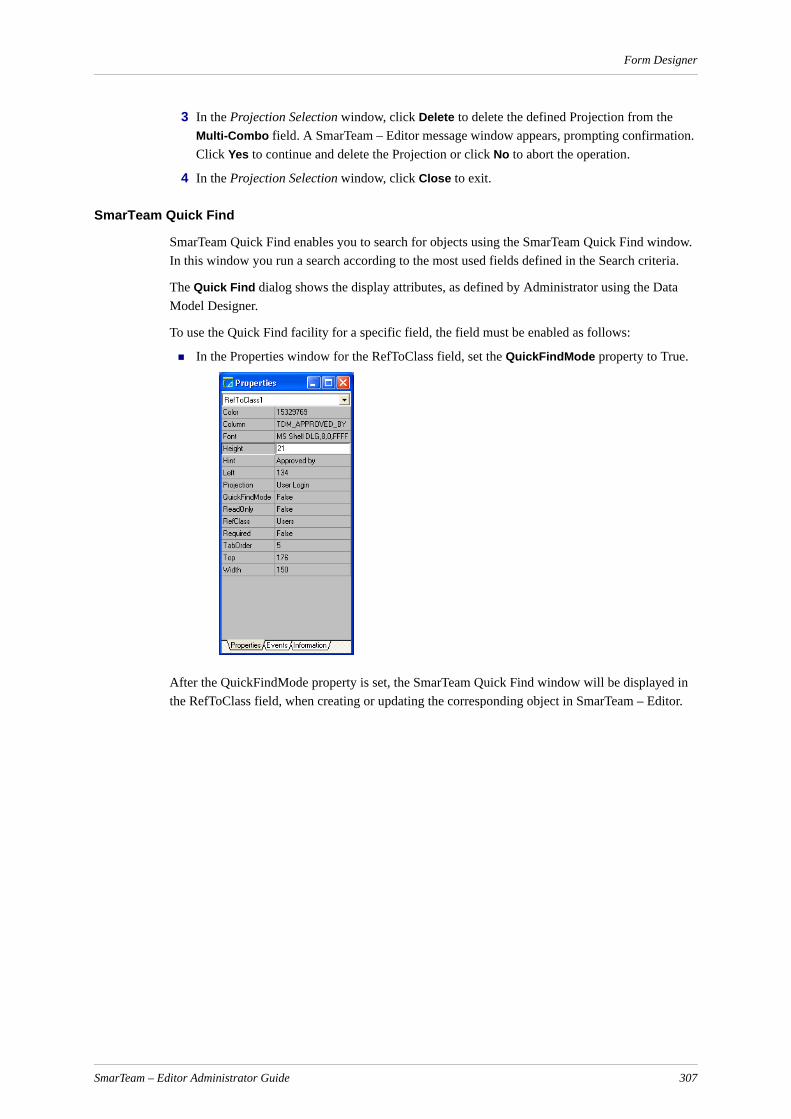
Form Designer
3 In the Projection Selection window, click Delete to delete the defined Projection from the Multi-Combo field. A SmarTeam – Editor message window appears, prompting confirmation. Click Yes to continue and delete the Projection or click No to abort the operation.
4 In the Projection Selection window, click Close to exit.
SmarTeam Quick Find
SmarTeam Quick Find enables you to search for objects using the SmarTeam Quick Find window. In this window you run a search according to the most used fields defined in the Search criteria.
The Quick Find dialog shows the display attributes, as defined by Administrator using the Data Model Designer.
To use the Quick Find facility for a specific field, the field must be enabled as follows:
In the Properties window for the RefToClass field, set the QuickFindMode property to True.
After the QuickFindMode property is set, the SmarTeam Quick Find window will be displayed in the RefToClass field, when creating or updating the corresponding object in SmarTeam – Editor.
SmarTeam – Editor Administrator Guide 307

Form Designer
For example, for the Contacts field, the following window appears:
Fill in the fields in the Quick Find window as follows:
1 Enter the search string in the ID field.
2 Enter the name of the Company in the Company field. (This field has different names for different classes).
3 Choose a state from the State combo box (for SolidWorks only).
4 Check Only Latest to search the latest public revision of documents that meet the search criteria or Only Mine to search in objects that belong to you only.
5 Click Run. If all the fields are blank, SmarTeam – Editor will search all objects from the Reference to Class.
6 Click Advanced to open the Query by Attributes screen and run an advanced query.
Note: If you search for a SolidWorks object that belongs to a revision-managed class, the state attribute will be also shown.
Browsing to Reference to Class Fields
Both the regular Reference to Class and the Reference to Class with search fields enable you to open a new separate view of the Reference to Class object.
Note: This functionality works in view mode only; it does not work in update mode.
To open a new view:
1 Double click on the Reference to Class field.
2 Right click and choose Open View with all SmarTeam options.
Copy and Paste in Reference to Class
To copy an object:
Select the object and type <Ctrl>+C.
To paste an object:
Type <Ctrl>+V in the desired location.
SmarTeam – Editor Administrator Guide 308
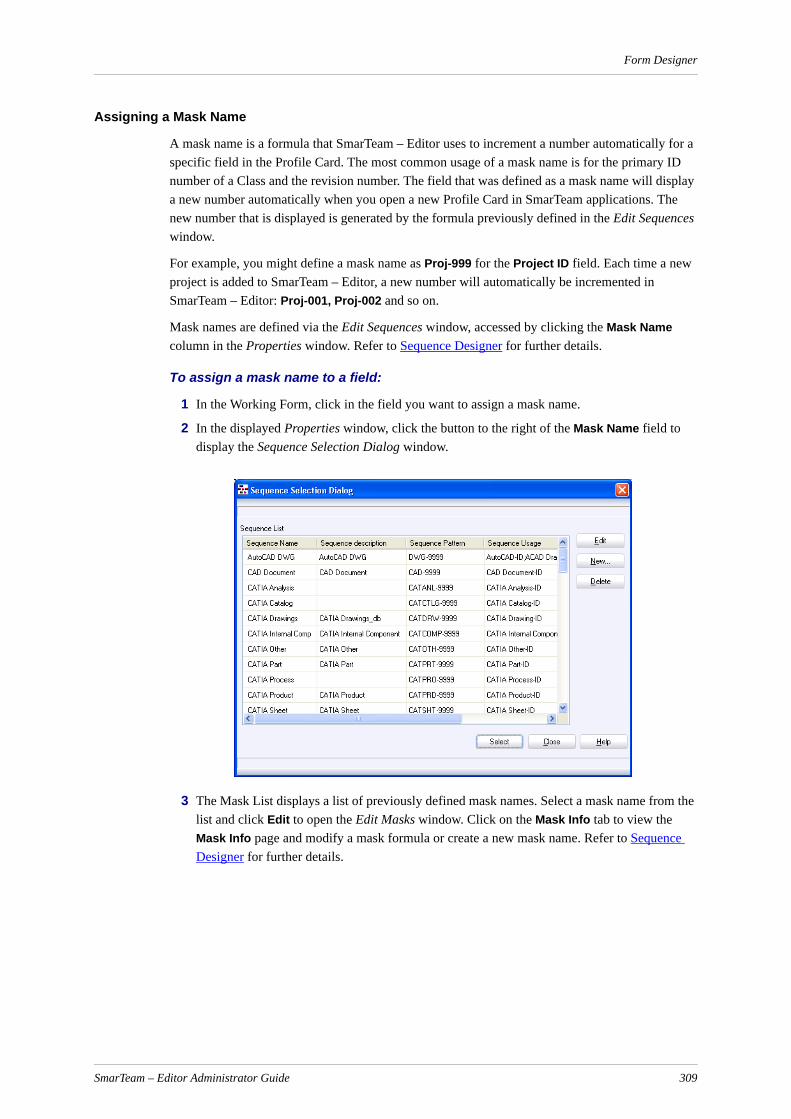
Form Designer
Assigning a Mask Name
A mask name is a formula that SmarTeam – Editor uses to increment a number automatically for a specific field in the Profile Card. The most common usage of a mask name is for the primary ID number of a Class and the revision number. The field that was defined as a mask name will display a new number automatically when you open a new Profile Card in SmarTeam applications. The new number that is displayed is generated by the formula previously defined in the Edit Sequences window.
For example, you might define a mask name as Proj-999 for the Project ID field. Each time a new project is added to SmarTeam – Editor, a new number will automatically be incremented in SmarTeam – Editor: Proj-001, Proj-002 and so on.
Mask names are defined via the Edit Sequences window, accessed by clicking the Mask Name column in the Properties window. Refer to Sequence Designer for further details.
To assign a mask name to a field:
1 In the Working Form, click in the field you want to assign a mask name.
2 In the displayed Properties window, click the button to the right of the Mask Name field to display the Sequence Selection Dialog window.
3 The Mask List displays a list of previously defined mask names. Select a mask name from the list and click Edit to open the Edit Masks window. Click on the Mask Info tab to view the Mask Info page and modify a mask formula or create a new mask name. Refer to Sequence Designer for further details.
SmarTeam – Editor Administrator Guide 309

Form Designer
4 Click Save to save your changes then click Close to return to the Sequence Selection Dialog window.
5 In the Sequence Selection Dialog window highlight the selected Mask Name then click Select to link the mask to the field previously selected in the Working Form. The Mask is displayed in the Mask Name field of the Properties window.
Moving or Resizing a Field
You can redesign the Profile Card by moving or resizing any of the fields in the Working Form window.
To resize/reposition a field(s)
1 Select the field and drag it to a new location or drag a sizing handle until the field is the required size. The fields's new size properties are automatically displayed in the Properties window.
SmarTeam – Editor Administrator Guide 310

Form Designer
2 You can group a number of fields together and reposition them as a group. While holding down the left mouse button, draw a box around the fields you want to group together, and reposition the selection: .
Grid Options
The Working Form window comprises of a grid that can be used to help you organize the exact location of the fields in the form.
To set grid options:
1 Select and highlight a field then right click to display the Grid options menu.
2 Select one of the grid options described below.
Align To Grid: Brings the selected field to the grid.
Bring To Front: Brings the selected field to the front (of another field). Use this option when you place one field over another. For example, you may place a Label field over a Panel field so that the label will appear on the raised panel in the Profile Card.
Send To Back: Sends the selected field to the back (of another field).
Align Controls…
Displays the Alignment window, allowing you to align two or more selected fields.
SmarTeam – Editor Administrator Guide 311
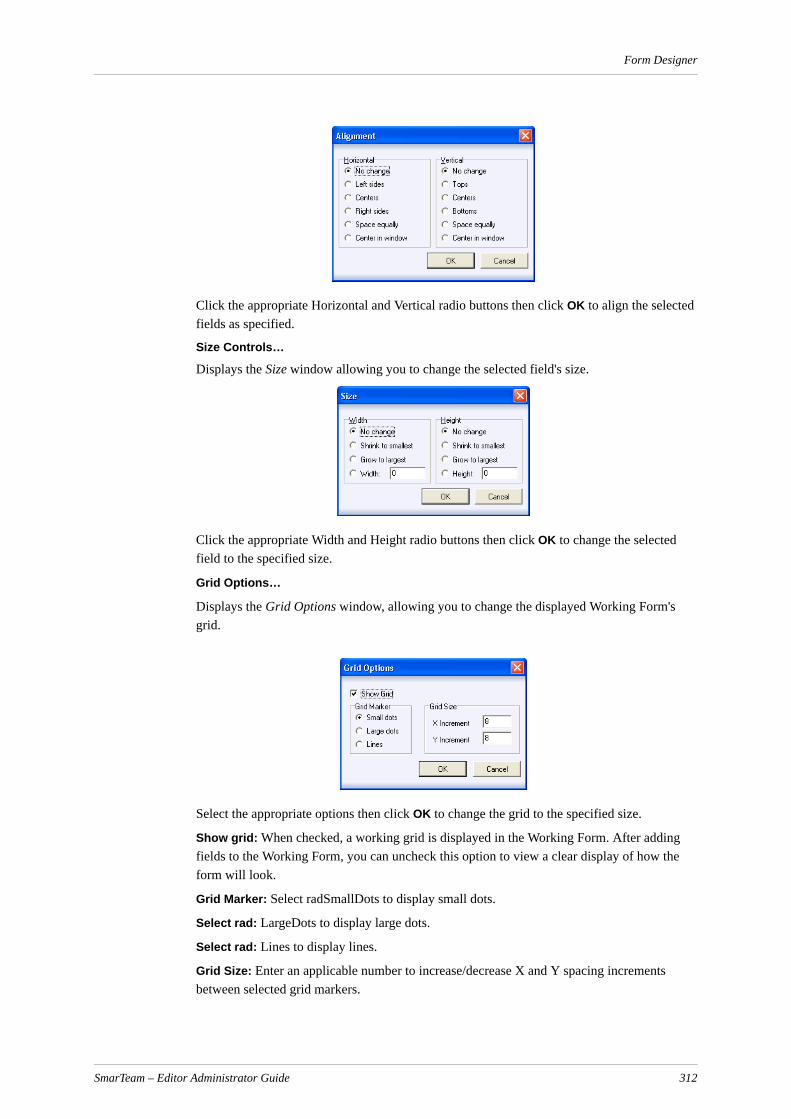
Form Designer
Click the appropriate Horizontal and Vertical radio buttons then click OK to align the selected fields as specified.
Size Controls…
Displays the Size window allowing you to change the selected field's size.
Click the appropriate Width and Height radio buttons then click OK to change the selected field to the specified size.
Grid Options…
Displays the Grid Options window, allowing you to change the displayed Working Form's grid.
Select the appropriate options then click OK to change the grid to the specified size.
Show grid: When checked, a working grid is displayed in the Working Form. After adding fields to the Working Form, you can uncheck this option to view a clear display of how the form will look.
Grid Marker: Select radSmallDots to display small dots.
Select rad: LargeDots to display large dots.
Select rad: Lines to display lines.
Grid Size: Enter an applicable number to increase/decrease X and Y spacing increments between selected grid markers.
SmarTeam – Editor Administrator Guide 312

Form Designer
Adding or Modifying a Tab
As described previously, the Profile Card can display sub page tabs that can present additional sub-pages of information.
In the selected Working Form, click on a tab to display the corresponding sub-page of the Profile Card. You can now proceed to modify these fields.
If required, you can add a new tab, modify an existing tab, change the order of tabs, or copy fields from one tab to another. When you add a new tab name, SmarTeam – Editor automatically displays a new Working Form in which you can design the sub-page that this tab will display. You can also delete or modify any existing tab pages. For example, if you add a tab named File2, you can create a new tab page with its own fields. When the user clicks the File2 tab in the Profile Card, the File2 tab page will be displayed.
To add a Tab Page:
1 From the Form Designer main menu select Action, New Tab to open the New Tab window.
2 In the New Tab window, Tab name field, enter a suitable name for the new tab page then click OK to continue.
A new blank page is now added to the selected Working Form and displayed. The tab name is the name entered in the New Tab window. You can now proceed to design the new page and add fields as described in the previous sections.
Note: A blank tab page cannot be saved.
To delete a Tab Page:
1 To delete a tab page, select and click on the tab page you want to delete.
2 From the Form Designer main menu select Edit, Delete Tab. A SmarTeam – Editor confirmation message is displayed.
3 Click Yes to delete the page or click Cancel to abort the operation. If you select Yes, the selected tab page and contents are automatically deleted from the Working Form. When you next launch SmarTeam – Editor, the deleted tab page will no longer appear in the Profile Card.
SmarTeam – Editor Administrator Guide 313
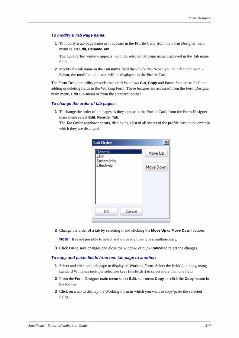
Form Designer
To modify a Tab Page name:
1 To modify a tab page name as it appears in the Profile Card, from the Form Designer main menu select Edit, Rename Tab.
The Update Tab window appears, with the selected tab page name displayed in the Tab name field.
2 Modify the tab name in the Tab name field then click OK. When you launch SmarTeam – Editor, the modified tab name will be displayed in the Profile Card.
The Form Designer utility provides standard Windows Cut, Copy and Paste features to facilitate adding or deleting fields in the Working Form. These features are accessed from the Form Designer main menu, Edit sub-menu or from the standard toolbar.
To change the order of tab pages:
1 To change the order of tab pages as they appear in the Profile Card, from the Form Designer main menu select Edit, Reorder Tab. The Tab Order window appears, displaying a list of all sheets of the profile card in the order in which they are displayed.
2 Change the order of a tab by selecting it and clicking the Move Up or Move Down buttons.
Note: It is not possible to select and move multiple tabs simultaneously.
3 Click OK to save changes and close the window, or click Cancel to reject the changes.
To copy and paste fields from one tab page to another:
1 Select and click on a tab page to display its Working Form. Select the field(s) to copy, using standard Windows multiple selection keys (Shift/Ctrl) to select more than one field.
2 From the Form Designer main menu select Edit, sub-menu Copy, or click the Copy button in the toolbar.
3 Click on a tab to display the Working Form in which you want to copy/paste the selected fields.
SmarTeam – Editor Administrator Guide 314
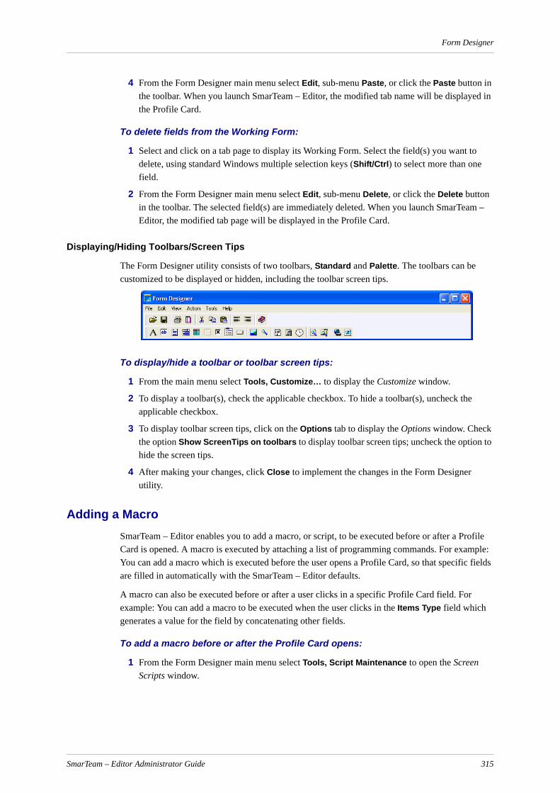
Form Designer
4 From the Form Designer main menu select Edit, sub-menu Paste, or click the Paste button in the toolbar. When you launch SmarTeam – Editor, the modified tab name will be displayed in the Profile Card.
To delete fields from the Working Form:
1 Select and click on a tab page to display its Working Form. Select the field(s) you want to delete, using standard Windows multiple selection keys (Shift/Ctrl) to select more than one field.
2 From the Form Designer main menu select Edit, sub-menu Delete, or click the Delete button in the toolbar. The selected field(s) are immediately deleted. When you launch SmarTeam – Editor, the modified tab page will be displayed in the Profile Card.
Displaying/Hiding Toolbars/Screen Tips
The Form Designer utility consists of two toolbars, Standard and Palette. The toolbars can be customized to be displayed or hidden, including the toolbar screen tips.
To display/hide a toolbar or toolbar screen tips:
1 From the main menu select Tools, Customize… to display the Customize window.
2 To display a toolbar(s), check the applicable checkbox. To hide a toolbar(s), uncheck the applicable checkbox.
3 To display toolbar screen tips, click on the Options tab to display the Options window. Check the option Show ScreenTips on toolbars to display toolbar screen tips; uncheck the option to hide the screen tips.
4 After making your changes, click Close to implement the changes in the Form Designer utility.
Adding a MacroSmarTeam – Editor enables you to add a macro, or script, to be executed before or after a Profile Card is opened. A macro is executed by attaching a list of programming commands. For example: You can add a macro which is executed before the user opens a Profile Card, so that specific fields are filled in automatically with the SmarTeam – Editor defaults.
A macro can also be executed before or after a user clicks in a specific Profile Card field. For example: You can add a macro to be executed when the user clicks in the Items Type field which generates a value for the field by concatenating other fields.
To add a macro before or after the Profile Card opens:
1 From the Form Designer main menu select Tools, Script Maintenance to open the Screen Scripts window.
SmarTeam – Editor Administrator Guide 315
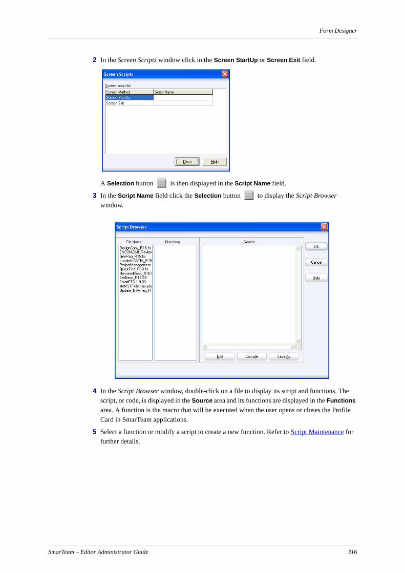
Form Designer
2 In the Screen Scripts window click in the Screen StartUp or Screen Exit field.
A Selection button is then displayed in the Script Name field.
3 In the Script Name field click the Selection button to display the Script Browser window.
4 In the Script Browser window, double-click on a file to display its script and functions. The script, or code, is displayed in the Source area and its functions are displayed in the Functions area. A function is the macro that will be executed when the user opens or closes the Profile Card in SmarTeam applications.
5 Select a function or modify a script to create a new function. Refer to Script Maintenance for further details.
SmarTeam – Editor Administrator Guide 316

Form Designer
6 Click OK to add the selected function to the Screen StartUp or Screen Exit field in the Screen Scripts window.
7 In the Screen Scripts window click Close to save your changes. When you open or close the Profile Card, the selected macro (function) is executed.
To add a macro before or after entering information in a field:
1 In the Working Form, select the field for adding a macro that will be executed before/after the user enters information in this field.
2 In the selected field's Properties window, click the Events tab to display the Events page.
3 Click in the OnEnter or OnExit field and click on the Selection button on the right side of the field. The Script Browser window is displayed, as shown in the previous section.
SmarTeam – Editor Administrator Guide 317

Form Designer
4 In the Script Browser window, select a file to display its script and functions. You can select a function or modify a script to create a new macro. Refer to Script Maintenance for further details.
5 In the Script Browser window, click OK to add the selected function to the OnEnter or OnExit field in the Properties window. The selected macro (event) will be executed before (OnEnter) or after (OnExit) the user clicks in the selected field in the Profile Card.
Saving a Working FormAfter creating or modifying a Working Form, you must save it to keep your changes. After saving your changes, launch SmarTeam – Editor to view the changes made to the specific Profile Card(s).
To save changes to a Working Form:
From the Form Designer main menu select File, Save, or click on the Save button in the toolbar to save changes made to the Working Form.
Note: Exiting the Form Designer window without saving changes will prompt a SmarTeam – Editor message advising you to save your changes.
Form Designer Menu BarThis section describes all menu and toolbar commands available from the Form Designer utility.
File Menu
Open…Opens the Profile Card window to select a Profile Card to open in the Working Form. Only one Profile Card can be opened at any one time. If a Profile Card is already open, you will be prompted to save any changes made to the Open Profile Card before you can open another Profile Card.
Save…When selected, saves any changes made to a Profile Card in the Working Form to the database.
PrintOpens a standard Print window to print the left pane of the SmarTeam window.
Print Setup…Opens a standard Print Setup window to set print options.
ExitExits the Form Designer utility. If changes were made to a Profile Card, you are prompted to save your changes before exiting.
Edit Menu
CutDeletes a selection and copies it to the clipboard.
CopyCopies a selection to the clipboard.
SmarTeam – Editor Administrator Guide 318

Form Designer
PastePastes a selection from the clipboard to the current cursor position.
Delete TabDeletes a selected tab page from the Profile Card currently displayed in the Working Form.
Rename TabRenames a selected tab page from the Profile Card currently displayed in the Working Form.
View Menu
PropertiesDisplays the Properties window for a selected field.
Work AreaMaximizes the Working Form and brings it to the front of the desktop.
Insert Menu
New Tab…Inserts a new tab page in the selected Profile Card displayed in the Working Form.
Tools Menu
Projection Maintenance…Opens the Projection Selection window to create, modify or select a Projection. A Projection is a list of referenced Class attributes for displaying in a multi-combo field in a Profile Card.
Scripts…Opens the Screen Scripts window for adding a macro or script before a Profile Card is opened, or to a specific field.
Customize…Opens the Customize window for customizing toolbars and toolbar screen tips.
Help Menu
Topic SearchOpens the Help file for the Form Designer utility.
About Form DesignerDisplays information about the Form Designer utility, such as the version number and creation date.
SmarTeam – Editor Administrator Guide 319
Web Form Designer
Web Form DesignerThe Web Form Designer is used to design and modify the layout and content of profile cards for SmarTeam – Web Editor. This function is usually performed by the system administrator.
The Profile Card provides an organized interface that displays the Class’s attributes. A Class is a set of objects that share common structure and common attributes. Each Class, e.g., Documents, Materials, Items, defined in SmarTeam has its own type of Profile Card.
You design and customize a profile card using the Web Form Designer working form. All changes made in the Web Form Designer are reflected in the Profile Card.
The Web Form Designer uses SmarTeam Visual Components to manage its interface. Custom scripts can be attached to an entire Profile Card or a single Control.
The designer can create and save Profile Card templates and attach them to a super-class in the system. The designer can import and export Profile Cards from/to a file.
Entering the Web Form DesignerThe Web Form Designer is access from the Admin Console utility.
To open the Web Form Designer Utility:
1 From Start button, select Programs, SmarTeam, Administrative Tools, Admin Console.
2 The SmarTeam User Login window opens. Enter your User Name and Password, if required, and click OK.
3 From the User Interface Management section, select Web Form Designer, and click on the link in the right pane.
The Web Form Designer Main Window appears.
Opening a Profile CardNote: If a Duplicate ID error message is displayed when trying to creating a new object for a new project, perform the following:.
1. In Admin Console, User Interface Management dialog, open the Web Form Designer.
2. From the File menu, click Open
3. Select the class Profile Card that you want to change
4. From the Tools menu, click Rename Controls
5. Click Save
All controls in the Profile Card recieve new unique ID numbers.
To open a working form:
1 From the File menu, select Open, or from the Toolbar, click
SmarTeam – Editor Administrator Guide 320

Web Form Designer
The Class Browser appears.
2 Select a class from the browser and click OK.
The working form of the selected class is displayed. A different working form is defined for each class type.
3 You can also search for a class in the Class Browser by pressing Ctrl+F.
4 The Find window appears:
5 Enter the string to search for and click OK.
The first occurrence of this string is highlighted. The Class Tree will be expanded automatically to show the string.
6 Press F3 to search for the next occurrence of the string.
Note: If the profile card of the selected class does not exist, when selecting an object in the Web Editor a profile card is created on the fly based on the default fields defined in the database (mandatory fields that are defined in the Data Model Designer). The profile card can then be modified and saved as required.
IMPORTANT! Changes made to the Profile Card in the Web Form Designer are not reflected in the Windows Form Designer and vice versa.
SmarTeam – Editor Administrator Guide 321
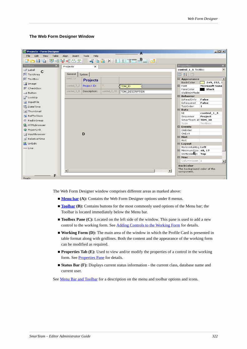
Web Form Designer
The Web Form Designer Window
The Web Form Designer window comprises different areas as marked above:
Menu bar (A): Contains the Web Form Designer options under 8 menus.
Toolbar (B): Contains buttons for the most commonly used options of the Menu bar; the Toolbar is located immediately below the Menu bar.
Toolbox Pane (C): Located on the left side of the window. This pane is used to add a new control to the working form. See Adding Controls to the Working Form for details.
Working Form (D): The main area of the window in which the Profile Card is presented in table format along with gridlines. Both the content and the appearance of the working form can be modified as required.
Properties Tab (E): Used to view and/or modify the properties of a control in the working form. See Properties Pane for details.
Status Bar (F): Displays current status information - the current class, database name and current user.
See Menu Bar and Toolbar for a description on the menu and toolbar options and icons.
AB
C
D
E
F
SmarTeam – Editor Administrator Guide 322

Web Form Designer
Menu Bar and ToolbarThe table below lists all the menu options and toolbar icons presented in the Web Form Designer.
Menu Option Icon Description
File New Create a new working form.
Open Open the Class Tree. From the Class Tree, select a class whose working form you want to change. Only one working form can be open at any one time. If a working form is already open, you will be prompted to save any changes before opening a new working form.
Close Close the current working form. If changes have been made to the working form after the last save, you are prompted to save before closing.
Import Import profile cards for selected classes in xml format. See Importing a Profile Card for details.
Export Export the profile cards for the selected classes. The profile cards are exported in xml format. See Exporting a Profile Card for details.
Revert Revert to the previously-saved version of this profile card.
Save Save any changes made to the working form in the database.
SaveAs... Save the current working form design for another class and link to a parent/project.
Page Setup Define and apply Page Setup parameters, e.g. Paper, Orientation and
Print Preview
Preview a page or pages before printing
Print Executes a print operation
Exit Exit the Web Form Designer. If changes have been made to the working form, you are prompted to save before exiting.
Edit Undo Undo the last action.
Redo Repeat the last action.
Cut Delete the current item selected and copy it to the clipboard.
Copy Copy the current item selected to the clipboard.
SmarTeam – Editor Administrator Guide 323

Web Form Designer
Paste Paste the contents of the clipboard to the current cursor position.
Delete Delete the currently selected element.
Select All Select all the elements in the working form.
View Toolbox Display/Hide the Toolbox pane.
Properties Display/Hide the Properties pane.
Table Add Column
Adds a column to the left of the selected column.
Add Row Adds a row above the selected row.
Delete Column
Delete the selected column in a table.
Delete Row Delete the selected row in a table.
Merge Cell Merge the selected cells into one cell.
Split Cell Split the selected merged cells into their original individual cells.
Align Align Left Align the contents of the current cell to the left.
Align Center
Center the contents of the cell vertically.
Align Right Align the contents of the current cell to the right.
Align Top Align the contents of the current cell to the top.
Align Middle
Center the contents of the cell horizontally.
Menu Option Icon Description
SmarTeam – Editor Administrator Guide 324

Web Form Designer
Toolbox Pane
This section presents an explanation of the contents and use of the Toolbox pane.
The Web Form Designer toolbox contains controls that are used to add/modify the fields on the working form.
List of Controls The Toolbox Pane contains the following controls:
Align Bottom
Align the contents of the current cell to the bottom.
Insert Tab Add a new tab to the working form.
Tools Projection Editor
Open the Projection Selection window to create, modify or select a Projection. A Projection is a list of referenced Class attributes for displaying data in a multi-combo field in a Profile Card. See Creating a RefToClass Control for details.
Rename Controls
If changes have been made in the ID field, reset the IDs of the controls in the Properties pane to their original definitions.
Reset Tab Order
If changes have been made in the Tab Order field, resets the order in which the fields will be selected to the original Tab Order default.Note: This may occur after upgrading the database between SmarTeam versions.
Help About Displays information about the Web Form Designer, such as the version number and creation date.
Contents Displays SmarTeam – Editor Online Help, Web Form Designer topics.
Menu Option Icon Description
Field Type Button Description
Label A label.
TextArea A notes area used to represent alphanumeric data from the attribute of type MEMO.
TextBox A box for insertion of text. A TextBox field is a field that displays alphanumeric data from the SmarTeam database.
SmarTeam – Editor Administrator Guide 325
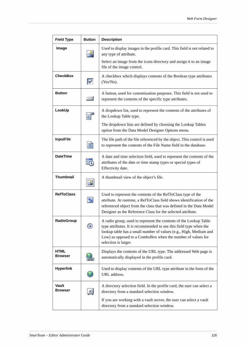
Web Form Designer
Image Used to display images in the profile card. This field is not related to any type of attribute.
Select an image from the icons directory and assign it to an image file of the image control.
CheckBox A checkbox which displays contents of the Boolean type attributes (Yes/No).
Button A button, used for customization purposes. This field is not used to represent the contents of the specific type attributes.
LookUp A dropdown list, used to represent the contents of the attributes of the Lookup Table type.
The dropdown lists are defined by choosing the Lookup Tables option from the Data Model Designer Options menu.
InputFile The file path of the file referenced by the object. This control is used to represent the contents of the File Name field in the database.
DateTime A date and time selection field, used to represent the contents of the attributes of the date or time stamp types or special types of Effectivity date.
Thumbnail A thumbnail view of the object’s file.
RefToClass Used to represent the contents of the RefToClass type of the attribute. At runtime, a RefToClass field shows identification of the referenced object from the class that was defined in the Data Model Designer as the Reference Class for the selected attribute.
RadioGroup A radio group, used to represent the contents of the Lookup Table type attributes. It is recommended to use this field type when the lookup table has a small number of values (e.g., High, Medium and Low) as opposed to a ComboBox when the number of values for selection is larger.
HTML Browser
Displays the contents of the URL type. The addressed Web page is automatically displayed in the profile card.
Hyperlink Used to display contents of the URL type attribute in the form of the URL address.
Vault Browser
A directory selection field. In the profile card, the user can select a directory from a standard selection window.
If you are working with a vault server, the user can select a vault directory from a standard selection window.
Field Type Button Description
SmarTeam – Editor Administrator Guide 326

Web Form Designer
IMPORTANT! Do not place more than one control in any cell of the profile card. If you need to place additional controls, create a new cell in the profile card for each desired control, and then drag-and-drop each control into a single cell.
Properties Pane
Each field added to the working form has predefined properties (such as color, font, layout, type, size) that can be modified as required. By default, these are shown on the right side of the Web Form Designer window.
The Properties pane is updated automatically every time a field is selected. Depending on the type of field selected, the Properties tab can contain different groups of properties and different properties in each group. See Modifying the Properties of a Control for a description of the properties that can be changed in the Properties tab.
An example of the properties of a text field is shown below.
RelativeTime Used to display the relative time. For example, the time passed in a flow process from the received time until the current time.
UrlEdit Used to display URL type of the attribute. When the URL is clicked, the appropriate Web page will open in the default Web browser.
Line A horizontal line in the form. The line serves as a separator between fields and/or groups.
Field Type Button Description
SmarTeam – Editor Administrator Guide 327

Web Form Designer
Creating a Form LayoutWhen you want to create a form layout, it is recommended to base your working form on an existing working form. You can then modify it by adding/deleting controls, adding groups, moving/resizing fields, adding/deleting cells to/from the table(s), adding tabs, etc. This section describes how to perform these operations.
Handling Layout Tables
When designing a working form for the profile card in the Web Form Designer, you need to create the form layout using layout tables. By default, each class has its own predefined layout table that you can change as required.
Layout tables help you to define the dimensions and sort order of your working form’s areas. Each layout table is comprised of different cells. In these cells, you can place text, images or controls.
To insert a row or column in a table:
1 Click inside the relevant table cell. Do not click inside a field.
2 From the toolbar select the required action, e.g. insert a row, insert a column.
Managing Controls of the Working Form
You can add functionality to the working form by inserting different controls.
All changes made to the working form in the Web Form Designer are reflected in the Profile Card. Based on the controls added, users filling out the form will be able to type text into text fields, select entries from a list in a combo box, mark check boxes, and click buttons to run commands.
This section describes how to add different types of fields to the working form, how to move and resize a field and how to add a table to the working form.
Notes:
a Some controls, such as text boxes, check boxes, combo boxes, etc. must be connected to the class attributes. This is done by assigning an Attribute Name in the Properties Tab for each control.
b In order to define a mandatory field for CATIA Web Integration you must set the field as Mandatory in the Data Model Designer. You cannot define a mandatory field for CATIA Web Integration in the Profile Card using the Form Designer or Web Form Designer.
c When initiating a process in SmarTeam – Editor, the system does not provide a warning if mandatory attributes on the process profile card are not filled in. The process is initiated but remains at the Initiator's node and does not move forward. Therefore, it is recom-mended that you define a script on the Before Send Accept for Start Node hook for the validation of the mandatory fields.
Adding/Modifying a Control in the Working Form
To add a control to the working form:
1 Drag a control from the toolbox pane into a table cell in the working form.
The cursor changes according to the current location. At a place that the control can be inserted, the cursor changes to .
SmarTeam – Editor Administrator Guide 328
Web Form Designer
At a place that the control cannot be inserted the cursor changes to .
2 At the desired location, release the mouse button.
Modifying the Properties of a Control
To modify the properties of a control:
1 Select and click on a control.
The Properties pane lists all the properties applicable to the selected control.
Property Description
Appearance Note: The Properties listed in the Appearance area depend on the type of control selected, and may include all or some of the properites described below.
BackColor The color for the background of this control. You can select a different color from the combo box. When this option is selected, three tabs, Custom, Web and System, appear. Select the colors for each of these options.
Caption The text of a label or the name of the database (TextBox) field.
Font (Collection)
The font of the item selected. You can select a different font from the Font Collection Editor using the Browse button.
ForeColor The color of the text in this field. You can select a different color by clicking on Down arrow.
VisibleInModes The modes in which this field will be visible in the profile card. The available modes are: Add, Print, Query, Update, View.
Fields in the working form can be set to be visible/hidden in these different modes as required. For example, you can define a status field to be displayed in View mode only and to be hidden in Add or Update.
Behavior
IsReadOnly? True or False to indicate if this field is read-only in the profile card (i.e., it cannot be modified).
IsRequired? True or False to indicate if this field is mandatory or optional.
TabOrder Indicates the order in which fields are selected in the Profile Card when the user presses the Tab key. The number entered in this field represents the field's location in the selection sequence. For example, if 2 is entered, this field will be selected after the user presses Tab once. By default, the Tab Order is the order in which the field is added to the working form.
Data
ID Id used to uniquely identify the control in the Profile Card.
Sequence Displays the name of the sequence for the specified field. See Assigning a Sequence Name and Pattern for details.
SmarTeam – Editor Administrator Guide 329
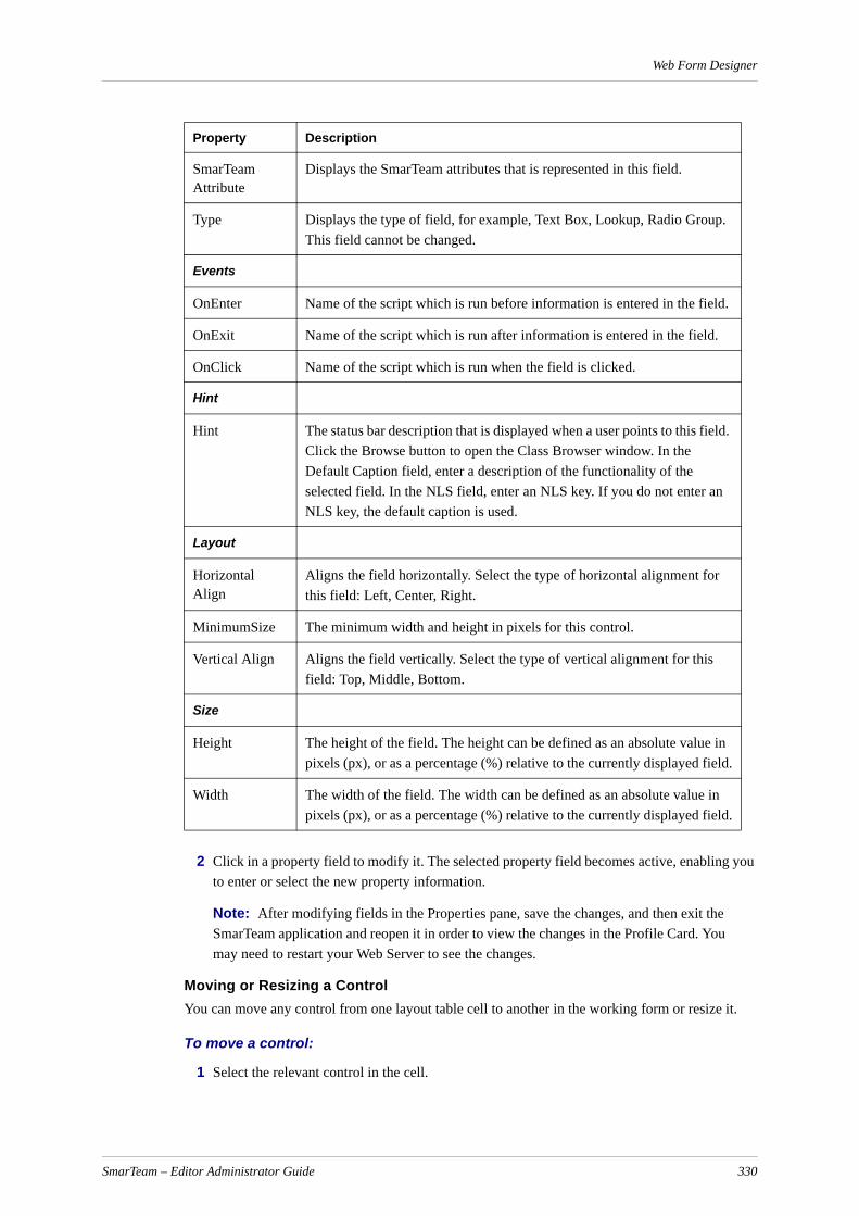
Web Form Designer
2 Click in a property field to modify it. The selected property field becomes active, enabling you to enter or select the new property information.
Note: After modifying fields in the Properties pane, save the changes, and then exit the SmarTeam application and reopen it in order to view the changes in the Profile Card. You may need to restart your Web Server to see the changes.
Moving or Resizing a ControlYou can move any control from one layout table cell to another in the working form or resize it.
To move a control:
1 Select the relevant control in the cell.
SmarTeam Attribute
Displays the SmarTeam attributes that is represented in this field.
Type Displays the type of field, for example, Text Box, Lookup, Radio Group. This field cannot be changed.
Events
OnEnter Name of the script which is run before information is entered in the field.
OnExit Name of the script which is run after information is entered in the field.
OnClick Name of the script which is run when the field is clicked.
Hint
Hint The status bar description that is displayed when a user points to this field. Click the Browse button to open the Class Browser window. In the Default Caption field, enter a description of the functionality of the selected field. In the NLS field, enter an NLS key. If you do not enter an NLS key, the default caption is used.
Layout
Horizontal Align
Aligns the field horizontally. Select the type of horizontal alignment for this field: Left, Center, Right.
MinimumSize The minimum width and height in pixels for this control.
Vertical Align Aligns the field vertically. Select the type of vertical alignment for this field: Top, Middle, Bottom.
Size
Height The height of the field. The height can be defined as an absolute value in pixels (px), or as a percentage (%) relative to the currently displayed field.
Width The width of the field. The width can be defined as an absolute value in pixels (px), or as a percentage (%) relative to the currently displayed field.
Property Description
SmarTeam – Editor Administrator Guide 330
Web Form Designer
2 Drag the control to the required cell.
To resize a control:
1 Select the relevant control.
2 Drag a sizing handle until the control is the required size. The control’s new size properties are automatically displayed in the Properties pane under Height and Width.
OR
Select the control and enter new values in the Height and Width fields of the Properties pane. The values can be entered in pixels (px), or as a percentage (%) of the currently selected field.
Merging or Splitting CellsYou can merge several cells or split merged cells in a layout table.
To merge cells:
1 Select the relevant cells using one of the following options:
Drag the mouse over the cells you want to merge, holding the left mouse button as you do so.
Select the cells you want to merge by holding the Ctrl key and clicking in each cell separately.
Note: There must be a total of one control in the cells you have selected.
2 Select a rectangle.
The perimeter must be a rectangle.
All cells within the perimeter must be selected.
Note: There must be a total of one control in the cells you have selected.
3 From the toolbar, select the Merge Cells option.
To split cells:
1 Select the relevant cell.
2 From the toolbar, select the Split Cell option.
Creating a Control to Display Lookup Classes A control to display lookup classes can be either of the type Combo Box or Radio Group. If it is a combo box type, it appears in the Profile Card as a dropdown list, enabling you to select one of its values.
To create a control that displays lookup classes:
1 Define the desired field as ComboBox or RadioGroup.
2 In the Attribute Name field of the Properties pane, select the database attribute to be linked to the control.
For full information on how to create class attributes of the Lookup Tables type and their values, refer to the Data Model Designer.
SmarTeam – Editor Administrator Guide 331
Web Form Designer
Adding a Hyperlink to the Working FormUsing the Web Form Designer, a hyperlink can easily be added to the working form. This is done by adding one of the following control types:
An HTML Browser window
A hyperlink (static)
A URL Edit field
When an HTML Browser window is added to a profile card, the Web page addressed by the corresponding attribute of the displayed object will automatically be displayed in the HTML window.
The URL Edit control displays the URL address stored in the corresponding attribute of the displayed object.
When a hyperlink field is added to a profile card, clicking on the defined hyperlink will open the Internet link via the user's default browser.
To place a hyperlink field in the working form:
1 From the Toolbox pane, click on either the HTML Browser, Hyperlink or URL Edit field type and drag it to the required cell in the working form.
2 In the displayed Properties pane of a Hyperlink or URL, click the Capture field and enter a name for the field (e.g., URL1).
3 For the URL Edit or HTML browser, click the SmarTeam Attribute property and select the attribute of the URL type.
4 For a Hyperlink, click the Navigate URL property and insert the URL.
Creating a RefToClass ControlFor details on how to create class attributes of type RefToClass, refer to Data Model Designer.
To create a new RefToClass control in the Web Form Designer:
1 Drag a RefToClass control from the toolbox into a cell on the working form.
2 In the SmarTeam Attribute field, select an attribute name to be related to this control. Only RefToClass fields are displayed.
Defining Projections for a RefToClass Control
A projection is a filter of objects from the referenced class that are displayed in the Profile Card using a search. For example, you can add a filter condition specifying that only those Projects created after April 1999 are displayed. When the user clicks on the arrow to the right of the multi-column field, only those Projects created after the specified date are displayed.
SmarTeam – Editor Administrator Guide 332

Web Form Designer
To add a projection:
1 In the Properties tab, click the button to the right of the Projection Name field to display the Projection Selection window.
2 In the Projection Selection window, click Add to create a new projection.
The Projection Details window appears.
3 Define the projection details for the selected Class as follows:
Class name: Displays the selected reference Class.
Projection name: Enter a suitable identifying name for the projection. This name will be displayed in the Projection Selection window.
Query name: If you need to filter the displayed Reference Class, click the Selection button to display the Search Editor window. Select an existing search or create a new search, according to your requirements.
For example, you can define or select a search of all Projects to filter Projects by their Creation Date. Only Projects that match this criteria will be displayed when the user clicks on the Reference field.
Separator: Enter a separator to display between attributes, such as a comma or semi-colon, for example: PR31,Water Pump or PR31;Water Pump.
Attributes: Displays the Select Attributes – Class [Name] window to allow you to define referenced Class attributes to display in the working form’s RefToClass control.
4 In the Projection Details window, click OK to save your changes, or click Cancel to abort any changes made, and return to the Projection Selection window. The Projection Selection window is redisplayed with the newly-defined projection.
You can add or modify other projections or select one from the list.
SmarTeam – Editor Administrator Guide 333
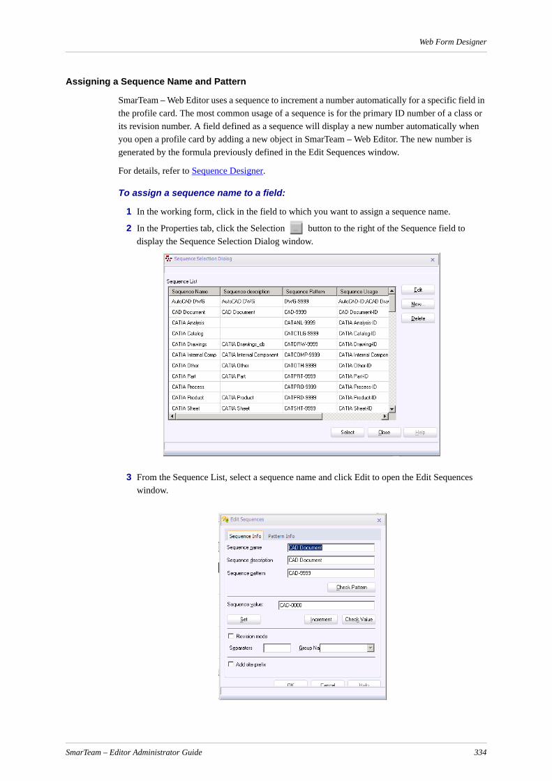
Web Form Designer
Assigning a Sequence Name and Pattern
SmarTeam – Web Editor uses a sequence to increment a number automatically for a specific field in the profile card. The most common usage of a sequence is for the primary ID number of a class or its revision number. A field defined as a sequence will display a new number automatically when you open a profile card by adding a new object in SmarTeam – Web Editor. The new number is generated by the formula previously defined in the Edit Sequences window.
For details, refer to Sequence Designer.
To assign a sequence name to a field:
1 In the working form, click in the field to which you want to assign a sequence name.
2 In the Properties tab, click the Selection button to the right of the Sequence field to display the Sequence Selection Dialog window.
3 From the Sequence List, select a sequence name and click Edit to open the Edit Sequences window.
SmarTeam – Editor Administrator Guide 334

Web Form Designer
4 In this window, you can view and edit existing sequences and their patterns.
5 Enter/modify values for the fields as described below.
6 Click Set to save the entered mask details or click OK to save the sequence.
7 Click Close to return to the Sequence Selection Dialog window. The new mask name now appears in the Mask List.
8 Click Select to link the new mask(s) to an attribute in the Sequence Designer window, closing the Sequence Selection Dialog window and returning to the Sequence Designer window. The mask now links to the attribute previously selected in the Sequence Designer window with the
Field Name Description
Sequence name Enter a name for the mask.
Sequence description
Enter a description for the mask. (This field is optional.)
Sequence pattern Enter the formula by which SmarTeam – Editor will increment the numbers in this field. Use the characters a and 9. The character a represents alphabetical increments. The character 9 represents numerical increments.For example: The Mask DOC-999 means that SmarTeam – Web Editor will increment the field as follows, DOC-001, DOC-002, and so on. The mask A9 means that SmarTeam – Editor will increment the field as follows: A0, A1, A9, B0, B1 and so on. Note: To modify the range of the formula, click the Pattern Info tab at the top of the window. Refer to Modifying the Range of a Mask.
Check Pattern Click on the Check Pattern button to view how the mask will be incremented. This checks if the mark is valid.
Sequence value Enter the baseline value and click the Set button. The mask formula will generate numbers starting from this value. Click the Increment button to increment the value for this field, and to view the incrementation pattern defined in the Sequence Pattern field.
Set Set the sequence value entered in the Sequence value field.
Increment Increment the numerical value in the Sequence value field.
Check Value Click on the Check Value button to check for syntax errors.
Revision mode When this mask is for a revision field, select the Revision mode checkbox. When this field is checked, the formula placed in the Mask field must contain a separator, such as a.9.
Separators When Revision mode is checked, the Separators field displays a selection of separators. This list displays suggestions only.
Group Name When Revision mode is checked, the Group field is active and displays the number of variables (with a separator) displayed in the Mask field. For example, for the mask a.9.9, a 3 is displayed in the Group field.
Add Site Prefix Select this check box to add the IP address of the client site to the sequence.
SmarTeam – Editor Administrator Guide 335

Web Form Designer
selected mask displayed in the Sequence name field. Note that it is not mandatory to perform this step at this time. A mask can be linked to an attribute at a later stage.
9 In the Sequence Designer window, click Close to save your changes and exit the Sequence Designer utility.
Adding a Script to a Profile Card
SmarTeam – Web Editor enables you to add a script of programming commands to be executed before or after a profile card is opened. For example, you can add a script which is executed before the user opens a profile card, so that specific fields are filled in automatically with the specific class defaults.
A script can also be executed before, at the moment when, or after a user clicks in a specific profile card control. For example, you can add a script to be executed when the user clicks in the Parts Type field which generates a value for the field by concatenating other fields.
To add a script before, at the moment when, or after a field is clicked:
1 In the Working area, select the field to which you want to add a script that will be executed.
2 In the selected field's Properties, click in the OnEnter, OnClick or OnExit field.
The Script window opens where you can create the script that will be executed.
3 Type in the script in the script area. You can add new functions or libraries as required.
Managing Tabs in the Form
When selecting a tab, you may edit the following properties:
SmarTeam – Editor Administrator Guide 336

Web Form Designer
Saving the Working FormAfter modifying the design of a Profile Card, you must save it to keep your changes. After saving your changes, launch SmarTeam – Web Editor to view the changes made to the specific profile card(s). If you do not see the changes, try restarting your Web Server.
To save changes made to the design of a profile card:
From the Web Form Designer menu bar, select File, Save, or click on Save in the toolbar.
Importing/Exporting Profile CardsThe Web Form Designer Import and Export utilities facilitate the process of building a new environment by exporting and importing existing profile cards in XML format.
Exporting a Profile Card
The Export operation allows you to export the profile cards of selected classes in XML format. The XML file represents the different layouts of all the selected classes. These profile cards can then be used to build a new environment.
To export a profile card(s):
1 From the File menu, select Export.
The Export Class Browser appears:
Property Description
Caption The text of the tab
Expanded Possible Values:
True: The tab is expanded by default when viewing the Profile Card
False: The tab is collapsed when viewing the Profile Card
VisibleInMode Select the mode(s) in which this tab will be visible. If no value is selected, the tab will be visible in all of the modes.
Id ID of the tab
SmarTeam – Editor Administrator Guide 337
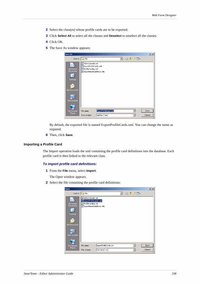
Web Form Designer
2 Select the class(es) whose profile cards are to be exported.
3 Click Select All to select all the classes and Deselect to unselect all the classes.
4 Click OK.
5 The Save As window appears:
By default, the exported file is named ExportProfileCards.xml. You can change the name as required.
6 Then, click Save.
Importing a Profile Card
The Import operation loads the xml containing the profile card definitions into the database. Each profile card is then linked to the relevant class.
To import profile card definitions:
1 From the File menu, select Import.
The Open window appears.
2 Select the file containing the profile card definitions:
SmarTeam – Editor Administrator Guide 338

Web Form Designer
3 Click Open.
4 The classes defined in the xml file are presented. For example:
5 Select the classes whose profile cards you want to import and click OK.
A warning message appears informing that existing profile cards will be overwritten.
6 Click OK to overwrite the existing profile cards.
Note: No validation is performed when loading the profile card. If the profile card component (field) was linked to a class attribute that does not exist, the link will be ignored and the administrator must modify the profile card manually in the new environment.
Controlling the Display of Fields in the Profile Card The profile card may be displayed in the SmarTeam – Web Editor in one of the following modes:
Add - When a new object is added to a specific class, the profile card is displayed in Add mode.
Update - When an object is being modified, the profile card is displayed in Update mode with specific fields enabled, allowing you to modify previously entered information and add new information where applicable.
View - When an object is first opened, the profile card is displayed in View mode. In this mode, you can view the contents of the fields in the profile card but cannot update them.
Query - When a query is to be performed on a field in the profile card, the profile card is displayed in Query mode to enable the user to enter a query condition.
Print - When you select the Print option to print the current profile card, the profile card is displayed in Print mode. This mode shows a preview of the printout
Fields in the working form can be set to be visible/hidden in these different modes as required in the Properties tab, VisibleInModes attribute. For example, you can define a status field to be displayed in View mode only and to be hidden in Add or Update.
SmarTeam – Editor Administrator Guide 339

SmarTeam File Converter
SmarTeam File ConverterIn order to display CAD files in 3Dvia Viewer, files must be converted to CGR format. The SmarTeam File Converter utility, which is a stand-alone conversion utility that is part of the SmarTeam - Editor installation, enables convert CAD files located in SmarTeam vault to CGR and CGM formats. In order to create CGM format (for CAD Drawings), customer should install ENOVIA DMU Navigator that is part of DS products
Installation and ImplementationInstallation of SmarTeam File Converter is part of the SmarTeam - Editor installation.
Implementation of this utility should be on a dedicated machine, which hosts an instance of the CAD used in the organization. If the organization works with more than one CAD, the machine must be able to work with those CADs that require conversions.
SmarTeam File Converter should be activated for the following scenarios:
Conversion of existing CAD data at the first time - Recommended running on separate envi-ronment (not production). If not possible, recommended to run during off hours and probably more than one night is required.
Conversion of new CAD data - Recommended running on dedicated machine.
In case of different Vault Servers (in a multi-site or multi-vault environment), conversion will be done for files located in local vault and not for replicated vaults. SmarTeam File Converter utility should be installed and run for all relevant Vault Servers
Running the Batch Converter Utility
To run the Batch Converter utility:
1 Using Search by Attribute or Search by Example, build a predefined query on the CAD docu-ments that need to be converted and save this query.
Example: Query on Assembly class where the file type is SolidWorks Assembly.
2 Run SmarTeam.Std.FileConverter.exe located under SmarTeam Home Directory \bin Folder.
3 The following GUI will appear:
a Select Query - Select one or more queries from the list box.
Queries available are the private queries of the current SmarTeam user and public queries.
b Start - Run the SmarTeam File Converter
Note: SmarTeam File Converter will convert the file only if the relevant CAD applica-tion is installed
c View Report - Show the log on the last run of this tool
d Save your queries - Save the selected queries to a XML file.
Next time SmarTeam File Converter run the queries will be selected by the definition in this file.
e Exit - Close the SmarTeam File Converter window.
SmarTeam – Editor Administrator Guide 340

SmarTeam File Converter
Behavior
The SmarTeam File Converter supports the following:
"Only supported files can be converted - refer list of supported file types in the Persistent Data.
"Naming Convention:
"Conversion process does not affect / modify the original files.
"The new CGR and PNG file name is the original file name including original extension and the new extension.Example:
– "Original file: <Part>.sldprt
– "CGR file: <Part>.sldprt.cgr
– "PNG file: <Part>.sldprt.png
"Multi-site \ Multi-vault
"When retrieving an assembly there might be different files in different Primary Vaults. In this scenario files are retrieved from Primary and Mirror Vaults for the conversion process. Only files originating from the Primary Vault are saved in the primary Vault with the CGR / PNG extension.
"The utility does not write to mirror vaults.
"Error Handling:
"If there are no files in the query results, an error message is sent to the log file.
"If a file type is selected that is not applicable to the installed CAD an error message is sent to the log file.
"Any error that occurs during the conversion with the exception of a lost connection results in an error message. The utility then continues converting the next file. Relevant error message appear in the Persistent Data section.
"Sample for log file name created while conversion: Link to Joe's Documents.4_16_2008 9_52_25 AM.html.
SmarTeam – Editor Administrator Guide 341

SmarTeam File Converter
onse rt of fig-
Persistent Data
3D Formats
2D Formats
The following is a list of messages in the log file:
CAD application
Software Version File in Vault Comments
CATIA V5R20, V5R21, V5-6R2012
• Parts file (.CATPart)• Product file (.CATProduct)• Process (.CATProcess)• Shape (.CATShape)
CGR conversion will be used for legacy data.
SolidWorks 2010, 2011 • Parts file (.sldprt)• Assembly file (.sldasm)
CGR
Inventor 2010, 2011 • Parts file (.ipt)• Assembly file (.iam)
CGR
Solid Edge V20, ST • Part file (.asm)• Part Sheet Metal (.psm)• Assembly file (.asm)• Weldment (.pwd)
CGR
Data Exchange
N/A • Stl file (.stl) CGR
CAD application
Software Version File in Vault Comments
CATIA V5R20, V5R21, V5-6R2012
• Drawing file (.CATDrawing CGM
SolidWorks 2010, 2011 • Drawing file (.slddrw) CGM
AutoCAD 2010, 2011 • Drawing file (.dwg) CGM
Inventor 2010, 2011 • Drawing file (.idw) CGM
Solid Edge V20, ST • Drawing file (.dft) CGM
Message type Message Comment
Successful conversion "Successfully converted"
Failed conversion "Failed on CGR conversion" or “Failed on conversion or part of SolidWorks configuration”
If the conversion process generates a valid respalthough there are no files created or files are paSolidWorks configuration, the entire file is onlyconverted once. Each object in the different conurations is not converted separately.
SmarTeam – Editor Administrator Guide 342

SmarTeam File Converter
.
ult,
DMU Configuration
In order to use the ENOVIA DMU Navigator you should define the following Configuration Settings using the SmarTeam System Configuration:
CATDMUUTILLITY - Convert STL to CGR
CATDMUUTILLITY2D - Convert CAD Drawing to CGM
Running in Silent Mode
To run SmarTeam File Converter in Silent Mode perform the following:
1. Install the SDK component in the SmarTeam – Editor installation.
2. Copy the File_Convertor_Stand_Alone.ebs file from <SmarTeam Home>\SDK\Samples\File_Convertor to the <SmarTeam Home>\bin on the machine where the SmarTeam File Converter is installed.
3. Save the file as .exe file via the SmartScript Editor.
4. The .exe should be run by the customer manually or can be defined to run from Windows Scheduled Tasks.
Prerequisite: The XML file that was created when clicking the Save your queries button defines the Silent Mode which Saved Queries uses.
File type "Not supported document type"
File retrieval “Skipped: File not in Vault”"Failed on fetch operation" Retrieves the files from Vault to temp directory
Insert file to vault "Failed on move cgr to vault operation"
Already exists "Skipped: CGR file already exists in vault"
Mirror documents "Skipped: Mirror document” If the document is retrieved from the Mirror Vait is converted at its original site.
No file attached "Skipped: file not attached" If an object exists without attached files.
SmarTeam – Editor Administrator Guide 343

DMD Mapping ToolWhen Express behavior is added to SmarTeam, the Data Model Designer creates predefined classes in the database, and adds attributes for them. If these classes already exist in the database, there may be unnecessary duplication of classes and attributes.
For example, if a customer had a class that managed Documents in their database, and the Express implementation also contains a class that manages Documents, the customer may want to have only one class for documents. In order to achieve this, he can map the Express Documents super-class to the customer Documents class. After mapping the super-class, the customer can also map the abstract and leaf classes.
After class mapping, the attributes of the Express Documents clasess will be added to the existing attributes of the customer Documents class. The customer can then map the Express attributes to existing attributes.
These mapping capabilities are available in a new tool named DMD Mapping Tool.
When using specific Express or Admin behavior, existing classes need to be mapped to Express classes. For example, customer Documents class to Express Documents class (the classes may have different names). For each class mapping, the customer needs to map existing attributes to the Express attributes. For example, the customer can map the existing description attribute ‘CN_DESCRIPTION’ to the Express description attribute ‘TDMX_DESCRIPTION’. This is done in the DMD Mapping Tool.
Note: For each class for which no mapping was defined, the Data Model Designer will create a new class.
After defining the mappings, the Mapping Tool:
Adds the internal name of the Express classes to the existing classes mapped.
Changes the customer attribute name for mapped attributes to the Express attribute name.
IMPORTANT!
1. The DMD Mapping Tool is only available on databases that do not have Item behavior.
2. Currently, the scenario of mapping an Item class that does not have Item behavior on the customer database, is not supported.
3. In V5R18 SP6 HF1, the customer can add SNE behavior but not SDE behavior.
Running the DMD Mapping Tool
To run the DMD Mapping Tool:
1 Run the Data Model Designer by selecting Start, Programs, SmarTeam, Administrative Tools, SmarTeam Data Model Designer.
2 Select File, Modify Database Structure.
3 From the list of databases, select the database to be modified and click OK.
SmarTeam – Editor Administrator Guide 344

DMD Mapping Tool
4 In the Available Mechanisms window, select the Express - Engineering (SNE) mechanism and click Next.
The User Defined Class Mapping window appears:
Note: For a new database, this window will not appear.
5 On the left side, the classes and attributes of the SmarTeam database are presented.
This list is produced by the Mapping Tool and cannot be changed by the user. For a detailed list of the Express classes, see SmarTeam Database Classes List
6 On the right side of the window the customer can map the classes and attributes of his database.
7 For each Express class that needs to be added, select a corresponding existing class from the Customer database. For example, Super-class Documents to Super-class TDMX_DOCUMENTS.
Note: Super-classes can only be mapped to super-classes and sub-classes to sub-classes.
8 For each attribute that needs to be mapped, select a corresponding existing attribute from the Customer database. For example, attribute CN_DESCRIPTION to attribute TDMX_DESCRIPTION.
Note: Reference to Class attributes cannot be mapped.
To help you to make a record of the classes you have already covered that do not need mapping, you can select the option No Mapping Needed from in the Target field list. See Mapping Naming Rules for details of naming in mapped classes and attributes.
9 Select Next to continue or Cancel to cancel the mapping and behavior selection.
A log file of the changes appears in the window. A sample log file is presented below.
*** Classes mapping ***
Class Contacts has been mapped to role TDMX_CONTACTSClass Customer has been mapped to role TDMX_CUSTOMERClass Manufacturer has been mapped to role TDMX_MANUFACTURERClass Vendor has been mapped to role TDMX_VENDOR
SmarTeam – Editor Administrator Guide 345
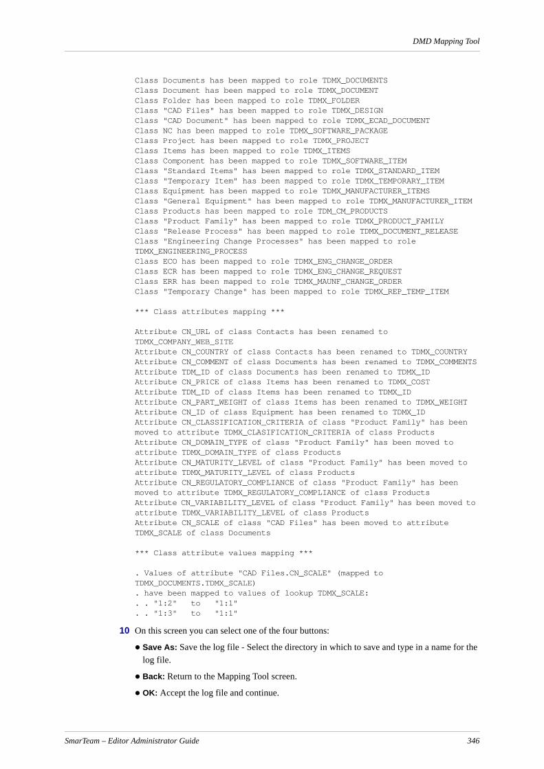
DMD Mapping Tool
Class Documents has been mapped to role TDMX_DOCUMENTSClass Document has been mapped to role TDMX_DOCUMENTClass Folder has been mapped to role TDMX_FOLDERClass "CAD Files" has been mapped to role TDMX_DESIGNClass "CAD Document" has been mapped to role TDMX_ECAD_DOCUMENTClass NC has been mapped to role TDMX_SOFTWARE_PACKAGEClass Project has been mapped to role TDMX_PROJECTClass Items has been mapped to role TDMX_ITEMSClass Component has been mapped to role TDMX_SOFTWARE_ITEMClass "Standard Items" has been mapped to role TDMX_STANDARD_ITEMClass "Temporary Item" has been mapped to role TDMX_TEMPORARY_ITEMClass Equipment has been mapped to role TDMX_MANUFACTURER_ITEMSClass "General Equipment" has been mapped to role TDMX_MANUFACTURER_ITEMClass Products has been mapped to role TDM_CM_PRODUCTSClass "Product Family" has been mapped to role TDMX_PRODUCT_FAMILYClass "Release Process" has been mapped to role TDMX_DOCUMENT_RELEASEClass "Engineering Change Processes" has been mapped to role TDMX_ENGINEERING_PROCESSClass ECO has been mapped to role TDMX_ENG_CHANGE_ORDERClass ECR has been mapped to role TDMX_ENG_CHANGE_REQUESTClass ERR has been mapped to role TDMX_MAUNF_CHANGE_ORDERClass "Temporary Change" has been mapped to role TDMX_REP_TEMP_ITEM
*** Class attributes mapping ***
Attribute CN_URL of class Contacts has been renamed to TDMX_COMPANY_WEB_SITEAttribute CN_COUNTRY of class Contacts has been renamed to TDMX_COUNTRYAttribute CN_COMMENT of class Documents has been renamed to TDMX_COMMENTSAttribute TDM_ID of class Documents has been renamed to TDMX_IDAttribute CN_PRICE of class Items has been renamed to TDMX_COSTAttribute TDM_ID of class Items has been renamed to TDMX_IDAttribute CN_PART_WEIGHT of class Items has been renamed to TDMX_WEIGHTAttribute CN_ID of class Equipment has been renamed to TDMX_IDAttribute CN_CLASSIFICATION_CRITERIA of class "Product Family" has been moved to attribute TDMX_CLASIFICATION_CRITERIA of class ProductsAttribute CN_DOMAIN_TYPE of class "Product Family" has been moved to attribute TDMX_DOMAIN_TYPE of class ProductsAttribute CN_MATURITY_LEVEL of class "Product Family" has been moved to attribute TDMX_MATURITY_LEVEL of class ProductsAttribute CN_REGULATORY_COMPLIANCE of class "Product Family" has been moved to attribute TDMX_REGULATORY_COMPLIANCE of class ProductsAttribute CN_VARIABILITY_LEVEL of class "Product Family" has been moved to attribute TDMX_VARIABILITY_LEVEL of class ProductsAttribute CN_SCALE of class "CAD Files" has been moved to attribute TDMX_SCALE of class Documents
*** Class attribute values mapping ***
. Values of attribute "CAD Files.CN_SCALE" (mapped to TDMX_DOCUMENTS.TDMX_SCALE). have been mapped to values of lookup TDMX_SCALE:. . "1:2" to "1:1". . "1:3" to "1:1"
10 On this screen you can select one of the four buttons:
Save As: Save the log file - Select the directory in which to save and type in a name for the log file.
Back: Return to the Mapping Tool screen.
OK: Accept the log file and continue.
SmarTeam – Editor Administrator Guide 346
DMD Mapping Tool
Cancel: Return to the Data Model Designer Mechanisms window without saving changes.
11 Click OK to begin the mapping process. For each attribute added, a message presenting the attributes that have been added appears. For example:
12 Click OK in the window of each message. After clicking OK in the last window, the next Data Model Designer window appears.
Mapping Naming Rules
Classes
Only the internal names of the classes are changed. The Class Name and Display Name willis not be changed. This change has no impact on the customer implementation.
Attributes
As attributes have no internal name, the attribute name itself is changed. Therefore, all references to the attributes must be updated accordingly. This is done by SmarTeam automatically only in the Admin Tools. For example, in Integration Tools Setup, Default Values, after mapping, the attribute names will be updated automatically.
Configuration Settings
Configuration settings affected by mapping in the mapping tool must be updated manually by the customer in the xml files.
It is recommended to delete all the user configuration settings and then update the other configura-tion settings for the changed attributes as necessary.
Scripts
The customer is responsible for updating all his scripts and DLLs to support the new attribute names.
SmarTeam – Editor Administrator Guide 347

DMD Mapping Tool
SmarTeam Database Classes ListThe following table presents a list of all the classes and sub-classes in the SmarTeam database.
Class Name Sub-Class Internal Name Class Name
TDMX_ADMIN TDMX_ADMIN_FOLDER Admin
TDMX_MESSAGES {For RCF Only}
TDMX_QUEUES {For RCF Only}
TDMX_MAIL {For RCF Only}
TDMX_OPERATION {For RCF Only}
TDMX_PRINT {For RCF Only}
TDMX_SETTINGS
TDMX_ADMIN_SETTING Admin Setting
TDMX_USER_SETTING User Setting
TDMX_CONTACTS TDMX_CUSTOMER Customer
TDMX_MANUFACTURER Manufacturer
TDMX_VENDOR Vendor
TDMX_CONTACT_PERSON Contact Person
TDMX_DOCUMENTS TDMX_DOCUMENT Document
TDMX_FOLDER Folder
TDMX_DESIGN
TDMX_ANALYSIS Analysis
TDMX_ANALYSIS_RESULT Analysis Result
TDMX_ASSEMBLY Assembly
TDMX_DESIGN_MANUFACTURING Design Manufacturing
TDMX_DESIGN_SPECIFICATION Design Specification
TDMX_DRAWING Drawing
TDMX_ECAD_DOCUMENT ECAD Document
TDMX_ECAD_PACKAGE ECAD Package
TDMX_EXCHANGE Exchange
TDMX_NC_FILE NC Files
TDMX_PART Part
TDMX_REPRESENTATION Representation
TDMX_SOFTWARE_PACKAGE Software Package
TDMX_STANDARD Standard
TDMX_PLANNING_DOCUMENT Planning Document
TDMX_ITEMS TDMX_ITEM Item
TDMX_SOFTWARE_ITEM Software Item
SmarTeam – Editor Administrator Guide 348

DMD Mapping Tool
SmarTeam Attributes List
TDMX_STANDARD_ITEM Standard Item
TDMX_TEMPORARY_ITEM Temporary Item
TDMX_MANUFACTURER_ITEMS TDMX_MANUFACTURER_ITEM Manufacturer Item
Class Name Sub-Class Internal Name Class Name
Class NameInternal Class Name Attribute Name
Attribute Display Name Attribute Type
Admin TDMX_ADMIN TDMX_ID ID Char(20)
TDMX_SUBJECT Subject Char(50)
TDMX_INSTRUCTIONS Instructions Memo
TDMX_SECTION Section
TDMX_VALUE_1 Value 1
TDMX_VALUE_2 Value 2
TDMX_VALUE_3 Value 3
TDMX_VALUE_4 Value 4
TDMX_VALUE_DESCRIPTION_1
Value 1 Description Char(255)
TDMX_VALUE_DESCRIPTION_2
Value 2 Description Char(255)
TDMX_VALUE_DESCRIPTION_3
Value 3 Description Char(255)
TDMX_VALUE_DESCRIPTION_4
Value 4 Description Char(255)
Messages TDMX_MESSAGES TDMX_MESSAGE Message
TDMX_ORIGINAL_MESSAGE Original Message
Contacts TDMX_CONTACTS TDMX_ADDRESS Address Char(50)
TDMX_CITY City Char(20)
TDMX_COMMENTS Comments Memo
TDMX_COMPANY_NAME Company Name Char(50)
TDMX_COMPANY_WEB_SITE Company Web Site URL
TDMX_CONTACT_NAME Contact Name
TDMX_COUNTRY Country
TDMX_EMAIL Email
TDMX_FAX Fax
TDMX_GENDER Gender
TDMX_ID ID
TDMX_PHONE Phone
TDM_SF_SECURE_LVL Security level outside flow proc
SmarTeam – Editor Administrator Guide 349

DMD Mapping Tool
TDM_SF_SERVICE Service field for SF managed
TDMX_STATE State
TDMX_TITLE Title
TDMX_ZIP_CODE ZIP code
Documents TDMX_DOCUMENTS TDMX_3D_CAD_IDENTIFIER 3D CAD Identifier
TDMX_CAD_IDENTIFIER CAD Identifier
TDMX_COMMENTS Comments
TDMX_SW_CONFIGURATION Design Configuration
TDMX_DETAILED_DESCRIPTION
Detailed Description
TDMX_FLOW_PROCESS_STATE
Flow Process State
TDMX_ID ID
TDMX_RELATED_ITEM_ID Item Number
TDMX_MATERIAL Material
TDMX_PAGE_SIZE Page Size
TDMX_RELATED_FLOW_PROCESS
Related Flow Process
TDMX_SCALE Scale
TDMX_TITLE_TYPE Title Type
Engineering Change Order
TDMX_ENG_CHANGE_ORDER
TDMX_ECR_ID ECR ID
TDMX_COST_IMPACT Cost
TDMX_COST_IMPACT_DESCRIPTION
Cost Description
TDMX_DOCUMENATION Documenation
TDMX_DOCUMENTATION_DESCRIPTI
Documentation Description
TDMX_OTHER Other
TDMX_OTHER_DESCRIPTION Other Description
TDMX_PERFORMANCE Performance
TDMX_PERFORMANCE_DESCRIPTION
Performance Descrip-tion
TDMX_PRODUCTION Production
TDMX_PRODUCTION_DESCRIPTION
Production Description
TDMX_PURCHASING_DESCRIPTION
Purchasing Descrip-tion
TDMX_PURCHSING Purchsing
Class NameInternal Class Name Attribute Name
Attribute Display Name Attribute Type
SmarTeam – Editor Administrator Guide 350
DMD Mapping Tool
TDMX_REGULATION Regulation
TDMX_REGULATION_DESCRIPTION
Regulation Description
Engineering Change Request
TDMX_ENG_CHANGE_REQUEST
TDMX_ROUTING Routing
TDMX_ROUTING_DESCRIPTION
Routing Description
TDMX_SCHEDULE Schedule
TDMX_SCHEDULE_DESCRIPTION
Schedule Description
TDMX_STOCK Stock
TDMX_STOCK_DESCRIPTION Stock Description
TDMX_TESTING Testing
TDMX_TESTING_DESCRIPTION
Testing Description
TDMX_TOOLING Tooling
TDMX_TOOLING_DESCRIPTION
Tooling Description
Items TDMX_ITEMS TDM_CLASSIFICATION Classification
TDMX_COST Cost
TDMX_CURRENCY Currency
TDM_DESCRIPTION Description
TDM_DETAILED_DESCRIPTION
Detailed description
TDMX_RELATED_FLOW_PROCESS
Flow Process
TDMX_FLOW_PROCESS_STATE
Flow Process State
TDMX_ID ID
TDMX_ITEM_TYPE Item Type
TDMX_LONG_LEAD_ITEM Long Lead Item
TDMX_ITEM_MATERIAL Material
TDMX_PHANTOM_ITEM Phantom Item
TDM_SF_SECURE_LVL Security level outside flow proc
TDM_SF_SERVICE Service field for SF managed
TDMX_SERVICE_ITEM Service Item
TDMX_STOCK_ON_HAND Stock On Hand
Items TDMX_ITEMS TDMX_STOCK_UNIT Stock Unit
TDMX_TOP_ITEM Top Item
Class NameInternal Class Name Attribute Name
Attribute Display Name Attribute Type
SmarTeam – Editor Administrator Guide 351

DMD Mapping Tool
SmarTeam – Engineering Express Issues
Configuration Settings for BOM Copy Tool
After adding the SNE mechanism to an existing database, the configuration settings for the config-uration set smarteam.std.configurationmanagement.config should be changed as described below.
Note: The <DB ID> represents the DB ID that is generated after creating the DB.Example of a PLMDB_R19 ID: 8C62BEEF01A8481BABCD79B4ECD4F0F4
On the SmarTeam server, perform the following:
1 Backup the mapping tool XML file:
<home dir>\ConfigurationSettings\Data\System\smarteam#$$<DB ID>\smarteam.std.configurationmanagement.config
2 To obtain the ConfigurationManagement for SNE Only.zip file:
a If you have installed a SmarTeam Express Demo Environment, copy it from:
<home dir>\Express_R19\SNE\Post Installation
b Replace this file with the file from the zip file:
<home dir>\Express_R19\SNE\Post Installation\ConfigurationManagement for SNE Only.zip
TDMX_ITEM_UPDATE_FROM_ERP
Update from ERP
TDMX_WAREHOUSE Warehouse
TDMX_WEIGHT Weight
TDMX_WEIGHT_UNIT Weight Unit
Manufacturer Items
TDMX_MANUFACTURER_ITEMS
TDMX_COMMENT Comment
TDMX_ID ID
TDMX_ITEM_WEB_SITE Item Web Site
TDMX_LAST_ORDERED_DATE Last Ordered Date
TDMX_MANUFACTURER Manufacturer
TDMX_MI_STATUS MI Status
TDMX_PRIORITY Priority
TDM_SF_SECURE_LVL Security level outside flow proc
TDM_SF_SERVICE Service field for SF managed
TDM_UOM Unit of Measure
Product Family TDMX_PRODUCT_FAMILY
TDM_CATEGORY Category
Class NameInternal Class Name Attribute Name
Attribute Display Name Attribute Type
SmarTeam – Editor Administrator Guide 352
Index
Index
Numerics3D XML 81
AActiveX 219Add Connection 73Add Mode 279Adding a Class 255Adding a Database Connection 73Adding a Field to the Working Form 294Adding a Hyperlink to the Profile Card 332Adding a Lookup Field in the Working Form 18, 302Adding a Macro 315Adding a New Application 190Adding a New Menu Item to a Sub-Menu 57Adding a Plug-in viewer using the Application Tools utility 221Adding an Internet Link to the Profile Card 302Adding Languages in the NLS System 228Adding New and Changing Existing Lifecycle Rules 118Adding or Modifying a Tab 313Adding or Modifying a TextEdit Field 298Adding User-defined Commands 59Adding, Deleting and Re-ordering the Tabs 277Admin Console 1
Accessing 2Administrator Options
Recommended 235ADO OLE DB Providers 77Advanced Setup 194Application
Adding New 190Deleting 192
Assign a script to the Login Screen 167Assigning a Lookup Table to an Attribute 266Assigning a Mask Name 309Assigning a Mask Name to a Field 309Assigning a Reference Class to an Attribute 265Assigning a Sequence Name 334Assigning a Sequence Name to a Field 334Assigning Authorizations 27
SmarTeam – Editor Administrator Guide 353

Index
Attach and Connect to an MSDE Database File 75Attaching a Script 211authentication manager 91Auto Form 277Automatic Links 269Available Databases 249
BBasic Concepts 246Browsing to Reference to Class Fields 308Building a SmarTeam Structure 244Built-in Viewer 196Button 293
CCaption 296, 329Changing Passwords 27Changing Vault Service Parameters 16Checkbox 293Checked-in Parents of Previous Revision 108Class 246
Adding 255Defining 258Deleting 257
Class Attributes 260Class Composition 272Class Name 283Class Prefix 258Class Tree 272Class Tree Window 266Color 296Column 296ComboBox 293Command Item 57Configuring Password Settings 160Conflicts in Lifecycle Rules 125Conversion Formats 235Convert the Class into a Class Tree 247Copy and Paste in Reference to Class 308Creating 332Creating a Lookup Field 18, 299, 331Creating a New Mask 173Creating a new object 247Creating a Profile Card 280Creating a SmarTeam Database Structure 280Creating an object tree 247Creating and Defining Classes 255Creating and Modifying a Form 275Creating objects 246
SmarTeam – Editor Administrator Guide 354

Index
Current Language 228Custom commands (currently not available in this version) 9Custom Contex 60Custom Contexts 63Customizing SmarTeam – Editor 6Customizing the SmarTeam – Editor Main Menu 48
DData Model Designer Menu Bar 282Database Connection
Adding 73Database-specific Components 77Date Edit 293Date Time Edit 293DB2 Database 75Default Hierarchical Links 269Default source 210Define a class 258define advanced parameters 194define an attribute 262Defining a class for each object 247Defining a Default Value 71Defining a Virtual Attribute 211Defining an Export 215Defining an Import 203Defining Applications 190Defining Attributes to Import 206Defining Class Composition 272Defining Export Properties 216Defining Groups 24Defining Indexes and Class Attributes 260Defining Lifecycle Options 101Defining Links and Link Attributes 268Defining Roles 25Defining the Index of a Class 267Defining the Values of a Lookup Table 299Defining Users 20Delete a Mask 175Delete an Application 192Delete an Embedded Viewer 199Delete Template 283Deleting a Class 257Deleting a Menu/Toolbar Command 56Deleting Menus/Toolbars 55Deleting User-defined Commands 61Dependencies between mechanisms 254Design Copy Tool 223Destination Database 249Destination Database – WizDst 286Directory Browser 294
SmarTeam – Editor Administrator Guide 355
Index
Displaying/Hiding toolbars/Screen tips 315
EEdit Menu 318Editing a Mask 174Editing Existing System Profiles 62Editing the Mask Range 176Editing the Properties of a General/Integration Rule 123Editing User-defined Commands 61Email Configuration 163Embedded Viewer
Deleting 199Embedded Viewer – AutoCAD and Autodesk Mechanical Desktop Formats 199Embedded Viewer Setup 195Error messages 226Events/Information Tabs 297Excel Table Cell
Mapping 81Export 214Export attributes 217Export Properties 216Exporting 218External Template 250
FField Display 283Field Name 283File Browser 294File Menu 282, 318Filtering the Import Process 203Filtering Tree Properties 105Finding and Replacing Localized Items 229Fixed Value 210Font 296Form Designer 277Form Designer Menu Bar 318Form Wizard 276French 226From File 208From Table 209
GGeneral Preferences 157German 226Getting Started
The Data Model 245Go to State 130Grid Options 311
SmarTeam – Editor Administrator Guide 356
Index
Group 24
HHeight 296, 330Help Menu 319, 325Hierarchical Links 268Hint 296HTML Browser 294, 326Hyperlink 294
Adding 332Adding to the Working Form 332
IIcon Browser 260Image 293, 326Image File 296Import 202Import a Lookup Class 214Import Sources 202, 208Import Template from Database 282Importing a Template from a Database 251Importing Links 212Importing/Exporting 337Index 267
Defining 260Inheritance 246Insert Menu 319, 325Integration Link Rules 116Integration Rule 123Integration Tool Setup Utility 78Internal Classes 285Internet Link 302
JJapanese 226Justification 296
LLabel 293, 325Language
Selecting 227Language Selection 286Languages
Adding 228Launching the Data Model Designer 248Launching the Database Connection Manager 72Launching the Menu Editor 47LDAP 94
SmarTeam – Editor Administrator Guide 357

Index
Lifecycle Options 236Lifecycle Options – General 103Lifecycle Options – Into Vault 105Lifecycle Options – Out of Vault 108, 113Lifecycle Rules 117Lifecycle Rules Setup 116Link Attributes 268Link class 268Linking Classes 212Links between super-Classes 269Load External Template 282Load Template 282Localization Table 228Lookup 293Lookup Table 266, 285, 299, 326
Attributes 207
MMacro 315Mail Configuration 163Making a Menu/Toolbar Command Invisible 56Mapping an Excel Table Cell 81Mask 210
Creating 173Deleting 175Editing 174
Mask Name 296, 309Assigning 309
Mask RangeEditing 176
Memo 293Menu Commands 9Menu Contexts 9Menu Editor
Upgrading from Previous Versions 66Menu Profiles 8Merging or Splitting Cells 331Metadata 226Modify an Existing Viewer for a File Type 196Modify Database Structure 283Modify Name of Existing Application 191Modify Template Attributes 282Modify Vault Server Details 12Modifying a Script 167Modifying the color, font and alignment of a Label or Field 277Modifying the Properties of a Field 295Moving or Resizing a Field 310, 330MS SQL or MSDE Database 75MSDE Database 75Multi-combo 303
SmarTeam – Editor Administrator Guide 358
Index
Multi-combo (Reference) Field 332Multi-Combo Box 293Multilanguage Enabler 230Multi-language Support 281Multi-site Data Model Wizard 286
NNegative Contexts 60New Template 282NLS Tasks 228
OObject 246OCX ActiveX 219Opening an Existing Working Form 291Opening the Web Form Designer Utility 320Options 284ORACLE Database 74
PPalette Toolbar 294Panel 293Partial Copy in Design Copy 225Password 26
Changing 27Password Rules 26Password Settings
Configuring 160Plug-in Viewer 197
Definitions 219Popup menus 7Preferences.NoUserNameinPassword key 26Preliminary Requirements 219Primary ID 267Primary Identifier 202Profile Card 290, 337Profile Cards 278Project Security 34Properties of a Field 295, 328Pulldown menus 7
RRadio Group 293, 326ReadOnly 296, 329Recommended Options 235Reference Class 265Reference to Class 207, 266, 293, 308, 326Reference to Class Quick Find 293
SmarTeam – Editor Administrator Guide 359

Index
Relative TIme 294, 327Released Parents of Previous Revision 108Removing a Context 60Role 24Role Designer 34Roles
Defining 25Running the Vault Default Utility 15
SSample Data Model Structure 245Save Template 283Save Template As 283Saving a Working Form 318, 337Saving in the Menu Editor 62Script
Modifying 167Selecting the Style Format for the Form 278Separator 57Sequence Name 334
Assigning 334Setting the NLS Root Path 230Shared directory 13Showing Existing Localizations 228SmarTeam Admin Console 1SmarTeam Structure 244Specifying Attributes for each Tab page 277Standard Commands 9SubMenu Item 57Summary 247Super Class 246System Configuration Keys
Preferences.NoUserNameinPassword 26useViewSecurity 115
System data 226System Profiles Menu 8
TTable Name 283TabOrder 297, 329Template
External 250Terminology 117Testing a Lifecycle Rule – Evaluate 124TextEdit 293The Data Model Designer Menu Bar 282The Multi-site Data Model Wizard 286The SmarTeam Vault 12Title 296Toolbar Manager Window 51
SmarTeam – Editor Administrator Guide 360
Index
Toolbars 7Tools Menu 284, 319, 325Top 297Translation 226Translation Utility 226Translation Utility User Interface 227
UUnderstanding SmarTeam – Editor Menus and Toolbars 7Update mode 279Updating a Profile Card 280User data 226User Defined Tools 164User Password 26User Profiles Menu 9User-defined Commands (scripts) 9useViewSecurity Key 115
VVault Browser 326Vault Default Utility 15Vault Service Parameters 16View Menu 283, 319View Options 241Viewer 293
Deleting 199Viewing a Form 276Viewing Lifecycle Rules 117Virtual Attribute 211Visual controls 226
WWeb Form Designer Utility
Opening 320Width 297, 330WizDst 286Workflow Options 239Working Form 291, 318
Saving 337Working with the Menu Editor 46
SmarTeam – Editor Administrator Guide 361


