Wisconsin Center for Applied Microelectronics 1550 Engineering Drive Phone: 608/262-6877 Madison, WI 53706 Fax: 608/265-2614 NIKON STEPPER NSR-2005i8A Rev. 2/20/14 Material Restrictions: Materials Allowed Materials Not Allowed Silicon Organic Polymers Silicon oxide Acids Silicon nitride Bases Polysilicon Solvents Quartz Spin on dopant Sodium Glass Polyimide tape III-V Semiconductors Polyimide Metals Polystyrene Gold* SU8 Carbon Photoresists Plastics * Gold is allowed only on the top side of the wafer and it needs to be covered with PR while inside the tool.
Transcript
Wisconsin Center for Applied Microelectronics
1550 Engineering Drive Phone: 608/262-6877 Madison, WI 53706 Fax: 608/265-2614
NIKON STEPPER NSR-2005i8A
Rev. 2/20/14
Material Restrictions:
Materials Allowed Materials Not Allowed
Silicon Organic Polymers
Silicon oxide Acids
Silicon nitride Bases
Polysilicon Solvents
Quartz Spin on dopant
Sodium Glass Polyimide tape
III-V Semiconductors Polyimide
Metals Polystyrene
Gold* SU8
Carbon
Photoresists
Plastics
* Gold is allowed only on the top side of the wafer and it needs to be covered with PR while inside the tool.
Stepper Specifications Model: Nikon NSR-2005i8A Stepper System Resolution: 0.5 µm on wafer level. There is a 5x feature size reduction from mask to wafer level (all features on
the mask are 5x larger than on wafer level). Maximum exposure field on wafer level is 21x21mm. Alignment: Automatic, with better than 0.14µm overlay accuracy. Uses either diffracted laser light (LSA) or,
for highly reflective surfaces where laser would not work well, CCD camera alignment (FIA) can be used.
Wavelength: 365nm, i-line from a high power mercury (Hg) lamp Mask size: 6"x6"x0.25" quartz glass, antireflective chrome, 2 µm flatness, can have more than one exposure
layer written on it Wafer size: 2", 3" and 4"
3
Checks Before Using the Stepper 1) In the back, check that the round switch is in the ON position. Light indicator “Main Line ON” should glow red indicating power being present. White light indicator above black ON button should be lit. This button does not turn on the Chamber, just provides power to it.
2) Check five red lights in the back of the environmental rack. Make sure none of them are lit - no error codes are present. Some of them may be lit if chamber was shut down due to e.g. water leak. If that is the case, compare light pattern to the table above it and notify staff member.
4
3) Check pressure on the two gauges on the left side of the tool. LO should be above 4 and HI should be around 15. Neither should be in the red range on the scale even though the LO one could be close to it like in the left picture below.
4) In the front of the machine check that green Chamber ON button is glowing (left picture below) and that chamber temperature is 20OC. This button starts the environmental chamber, water, and cooling Freon flow. 5) Check that SUP and VAC gauges show levels that are within the black range – like in the right picture below.
5
6) Verify the status of the lamps. Small FIA lamp is located in the back of the tool on its top. The small switch on the lamp housing should be in the ON position. You can also see lamp glow emanating from the housing. If the switch is on but lamp doesn’t glow, notify the staff. Main lamp status can be checked in front of the machine. Green LED should be ON and Start button glows yellow.
If you need to turn FIA lamp on, flip the small switch on the FIA housing to ON position. To turn main lamp on, you need to be at the stepper front side. Flip Power switch to ON position – LED glows green. Wait few seconds for all voltages to stabilize and power supply fans to speed up. Press “START” button – lamp starts immediately but is not ready for use right away. Recommended wait time for best exposure results is at least 2 hours after turning it on. If the stepper won’t be used for a long time, you may need to turn lamps off. Flip the small switch on the FIA housing to OFF position to turn off FIA lamp. To turn main lamp off, depress “Start” button on the front side of the stepper. This will turn the lamp OFF. Flip the power switch into OFF position – green LED stops glowing. Never press red Hour Rest button!! This is for staff use only when replacing the lamp. 7) Check if laser lights inside the chamber are glowing steady. Stage laser is located behind left side panels and is most easily visible through the leftmost (metal) chamber door. If one of the lights is blinking it may be because chamber has been powered down recently and laser needs to warm up. Wait 5-10 minutes. 8) Check if stepper is set to the wafer size that you will be using. Open chamber front doors and look for the round knob on the right hand side. It has number on it showing current wafer size.
6
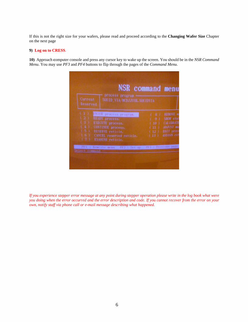
If this is not the right size for your wafers, please read and proceed according to the Changing Wafer Size Chapter on the next page 9) Log on to CRESS. 10) Approach computer console and press any cursor key to wake up the screen. You should be in the NSR Command Menu. You may use PF3 and PF4 buttons to flip through the pages of the Command Menu.
If you experience stepper error message at any point during stepper operation please write in the log book what were you doing when the error occurred and the error description and code. If you cannot recover from the error on your own, notify staff via phone call or e-mail message describing what happened.
7
Changing Wafer Size Before exposure, check if stepper is set for the wafer size you will be using. Open chamber front doors and look for the round knob on the right hand side. It has number on it showing current wafer size. If this is not the right size for your wafers, proceed with the following steps. Otherwise, skip to the next chapter – Select Program, Load and Align Reticle.
1) Start by opening two grey doors on the front side of the tool. 2) Move white wafer cassette out of the way (best place is on the top shelf behind the right set of grey doors). 3) Press emergency stop button close to where wafer cassette was. It will glow red. 4) Turn rotary knob above flat finding stage into right position - 2” or 3”. You can feel the metal knob “lock” into place. If changing to 4” wafer size, skip this step and do it after all other steps (in step 11) or you will not be able to rotate cover in the next step. 5) Rotate metal cover above the flat finding stage out of the way (towards the front of the stepper). Be careful not to catch any wires that may be in its way. 6) Using two rotary knobs on the right, move two question mark shaped arms towards the front of the stepper. Make sure you do not hit other parts with these arms – observe their movement as you do it. 7) Be extra careful during this step not to lean on any sensitive parts inside the stepper! Reach in and move small silver lever on the wafer stage to the appropriate position. This is done based on previous experience you gained during training. There is no click or other particular way to know that lever is in the right position. You will get a better sense of it by practicing. All the way in is the 2” position, somewhere approximately in the center of travel is the 3” position and all the way towards the front side is the 4” position. See picture below.
8
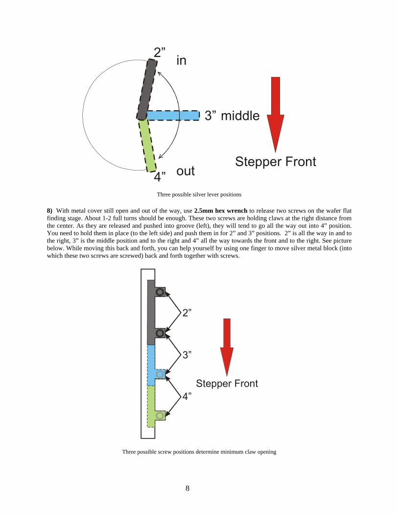
Three possible silver lever positions
8) With metal cover still open and out of the way, use 2.5mm hex wrench to release two screws on the wafer flat finding stage. About 1-2 full turns should be enough. These two screws are holding claws at the right distance from the center. As they are released and pushed into groove (left), they will tend to go all the way out into 4” position. You need to hold them in place (to the left side) and push them in for 2” and 3” positions. 2” is all the way in and to the right, 3” is the middle position and to the right and 4” all the way towards the front and to the right. See picture below. While moving this back and forth, you can help yourself by using one finger to move silver metal block (into which these two screws are screwed) back and forth together with screws.
Three possible screw positions determine minimum claw opening
2”
3”
4”
in
middle
outStepper Front
2”
3”
4”Stepper Front
9
9) Once in the right position, tighten the screws using hex wrench. If procedure is done properly, you should be able to move claws freely out, they should automatically move back in but not beyond the limit of the set wafer size. 10) Rotate metal cover back in place, taking care of the wires that might be in the way. 11) Skip this step if you were changing to 2” or 3” wafer size. You already turned this knob in step 4. If you are changing to 4” size, turn rotary knob above flat finding stage into 4” position. You can feel it “lock” into place. 12) Before proceeding, check if you changed all three settings: - Silver lever is in the right position - Two screws are in the right position - Rotary knob is showing needed wafer size 13) Go to console, open top metal door above keyboard and press “Wafer Loader Reset” button. It will blink red while wafer loader is resetting into initial position. Once finished, “Ready” button close to the wafer cassette position will glow green. 14) Put the right size wafer cassette with your wafer in it back in place.
10
Select Program, Load and Align Reticle
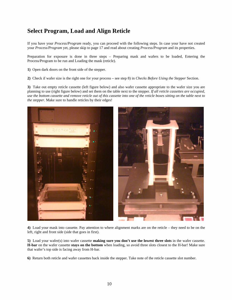
If you have your Process/Program ready, you can proceed with the following steps. In case your have not created your Process/Program yet, please skip to page 17 and read about creating Process/Program and its properties. Preparation for exposure is done in three steps – Preparing mask and wafers to be loaded, Entering the Process/Program to be run and Loading the mask (reticle). 1) Open dark doors on the front side of the stepper. 2) Check if wafer size is the right one for your process – see step 8) in Checks Before Using the Stepper Section. 3) Take out empty reticle cassette (left figure below) and also wafer cassette appropriate to the wafer size you are planning to use (right figure below) and set them on the table next to the stepper. If all reticle cassettes are occupied, use the bottom cassette and remove reticle out of this cassette into one of the reticle boxes sitting on the table next to the stepper. Make sure to handle reticles by their edges!
4) Load your mask into cassette. Pay attention to where alignment marks are on the reticle – they need to be on the left, right and front side (side that goes in first). 5) Load your wafer(s) into wafer cassette making sure you don’t use the lowest three slots in the wafer cassette. H-bar on the wafer cassette stays on the bottom when loading, so avoid three slots closest to the H-bar! Make sure that wafer’s top side is facing away from H-bar. 6) Return both reticle and wafer cassettes back inside the stepper. Take note of the reticle cassette slot number.
11
7) From the NSR Command Menu choose menu item (1) – Enter Process Program. In the next screen, choose Select Process Program.
8) In the table of Process/Program files, select the one you created previously. If you cannot find your Process/Program look for it at the next page (PF4) or you may need to load it in this list first. See the Section on loading Program into Workspace later in this manual. When done, return to NSR Command Menu using PF keys.
12
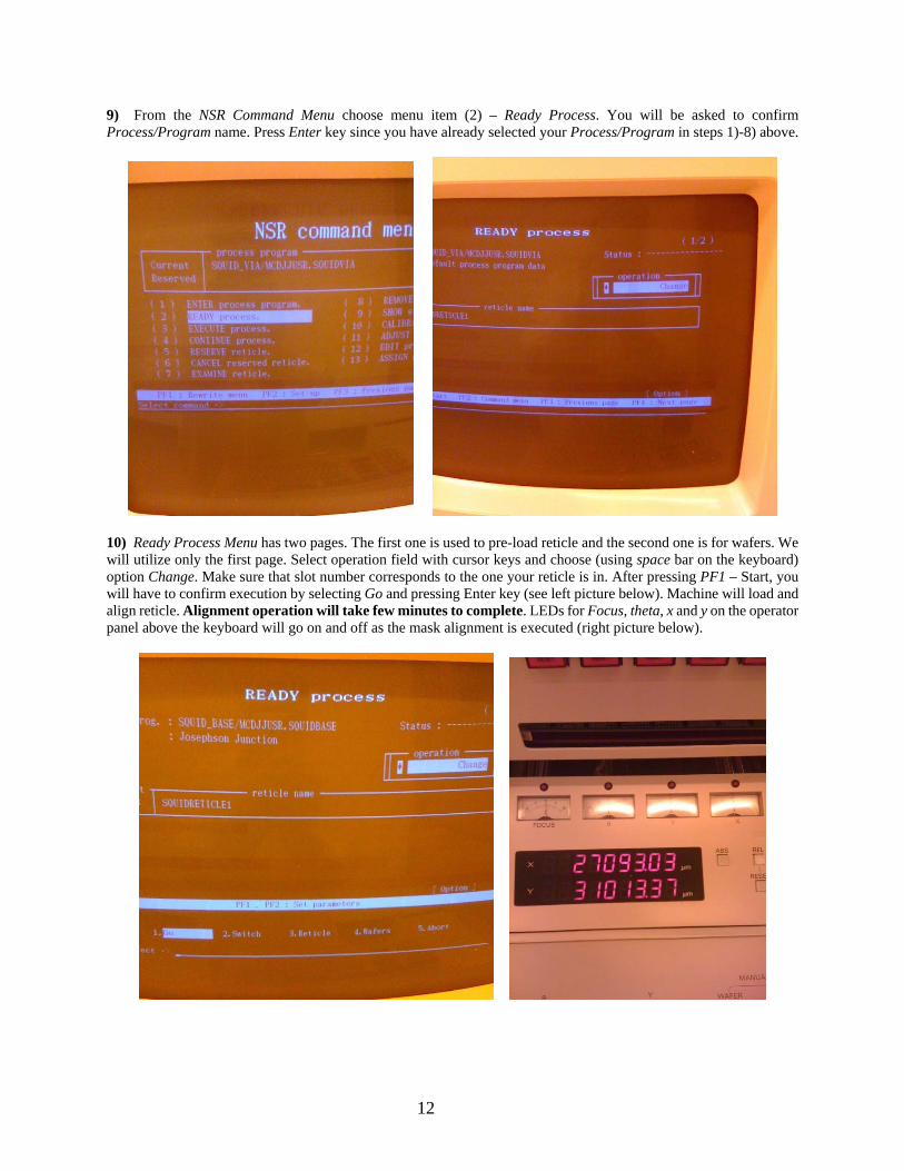
9) From the NSR Command Menu choose menu item (2) – Ready Process. You will be asked to confirm Process/Program name. Press Enter key since you have already selected your Process/Program in steps 1)-8) above.
10) Ready Process Menu has two pages. The first one is used to pre-load reticle and the second one is for wafers. We will utilize only the first page. Select operation field with cursor keys and choose (using space bar on the keyboard) option Change. Make sure that slot number corresponds to the one your reticle is in. After pressing PF1 – Start, you will have to confirm execution by selecting Go and pressing Enter key (see left picture below). Machine will load and align reticle. Alignment operation will take few minutes to complete. LEDs for Focus, theta, x and y on the operator panel above the keyboard will go on and off as the mask alignment is executed (right picture below).
13
Expose Wafers Checklist before exposure:
1) Process/Program has been selected using Enter Process/Program Menu. 2) Mask is loaded and aligned using Ready Process Menu. 3) Wafers are covered with photoresist, sitting in the cassette inside the stepper. 4) Stepper is set to the right wafer size you will be using.
1) From the NSR Command Menu choose menu item (3) – Execute Process. You will be asked to confirm Process/Program. Press Enter key to confirm.
2) The first page in this menu is related to loading and/or changing the mask. Since mask is already loaded, check only if the mask name corresponds to the one in the loaded Process/Program. Operation field for the mask on this page should be No Operation (like in picture below). Proceed to Page 2 by pressing PF4.
14
3) In page 2, we first need to enter the right number of wafers to be exposed. Select Wafers number field in the table (see picture below) using cursor keys, type the right number of wafers to be exposed and press Enter. Move to the Exposure time field and enter the right time if you need to change it. Exposure times are based on photo resist thickness and sensitivity but are usually in the range of 200-400msec.
4) Press PF1- Start. You will be asked to confirm execution by selecting Go and pressing Enter key. This will consecutively load wafer onto stage, expose it according to the selected Process/Program and unload it back into wafer cassette once exposure is finished. The same will be repeated for the second and the rest of the wafers in the batch. In case you have alignment specified in you program you will be asked to assist using stage joystick. 5) Buzzer will sound once exposure is complete. Silence the buzzer by pressing the Buzzer Off button.
15
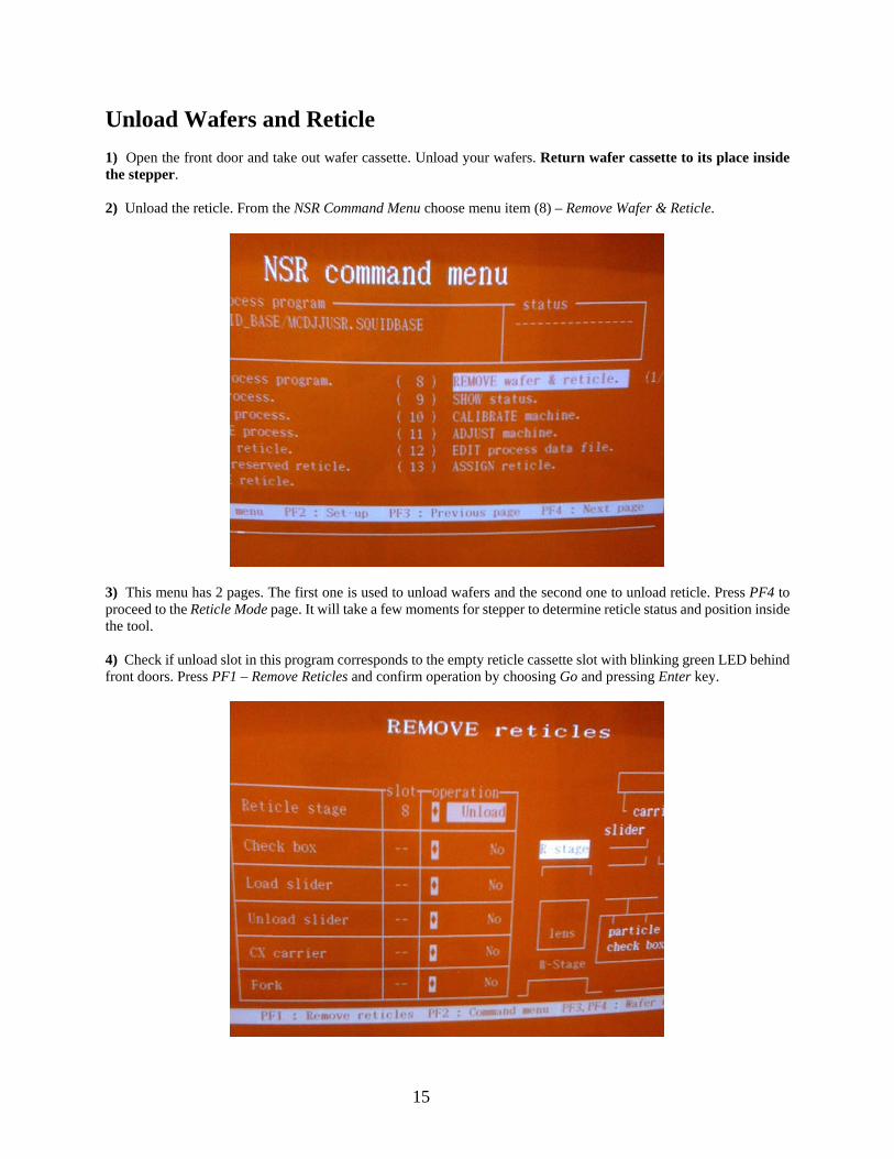
Unload Wafers and Reticle 1) Open the front door and take out wafer cassette. Unload your wafers. Return wafer cassette to its place inside the stepper. 2) Unload the reticle. From the NSR Command Menu choose menu item (8) – Remove Wafer & Reticle.
3) This menu has 2 pages. The first one is used to unload wafers and the second one to unload reticle. Press PF4 to proceed to the Reticle Mode page. It will take a few moments for stepper to determine reticle status and position inside the tool. 4) Check if unload slot in this program corresponds to the empty reticle cassette slot with blinking green LED behind front doors. Press PF1 – Remove Reticles and confirm operation by choosing Go and pressing Enter key.
16
5) Once unloaded, store reticle in the reticle box and in your assigned storage box. Do not keep reticle cassettes on the work bench next to the stepper! 6) Keep the work table clean – remove all papers, notes, and log books that you have brought in with you. This area will be periodically cleaned. Notebooks found (except official log book) will be moved to lost and found bin, free sheets of paper/notes will be discarded. 7) Log-off from CRESS. If you experience stepper error message at any point during stepper operation please write in the log book what were you doing when the error occurred and the error description and code. If you cannot recover from the error on your own, notify staff via phone call or e-mail message describing what happened.
17
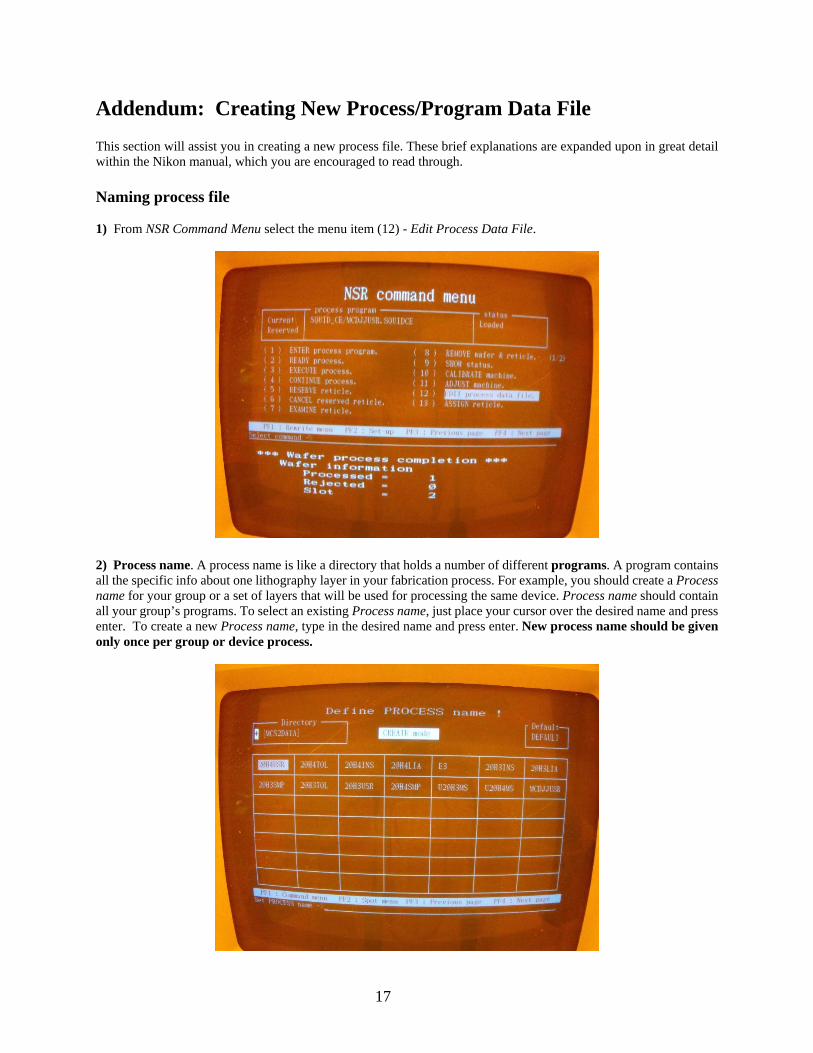
Addendum: Creating New Process/Program Data File This section will assist you in creating a new process file. These brief explanations are expanded upon in great detail within the Nikon manual, which you are encouraged to read through. Naming process file 1) From NSR Command Menu select the menu item (12) - Edit Process Data File.
2) Process name. A process name is like a directory that holds a number of different programs. A program contains all the specific info about one lithography layer in your fabrication process. For example, you should create a Process name for your group or a set of layers that will be used for processing the same device. Process name should contain all your group’s programs. To select an existing Process name, just place your cursor over the desired name and press enter. To create a new Process name, type in the desired name and press enter. New process name should be given only once per group or device process.
18
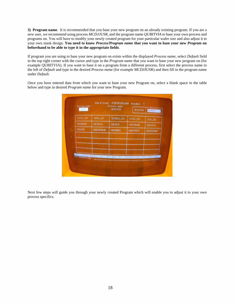
3) Program name. It is recommended that you base your new program on an already existing program. If you are a new user, we recommend using process MCDJJUSR, and the program name QUBITVIA to base your own process and programs on. You will have to modify your newly created program for your particular wafer size and also adjust it to your own mask design. You need to know Process/Program name that you want to base your new Program on beforehand to be able to type it in the appropriate fields. If program you are using to base your new program on exists within the displayed Process name, select Default field in the top right corner with the cursor and type in the Program name that you want to base your new program on (for example QUBITVIA). If you want to base it on a program from a different process, first select the process name to the left of Default and type in the desired Process name (for example MCDJJUSR) and then fill in the program name under Default. Once you have entered data from which you want to base your new Program on, select a blank space in the table below and type in desired Program name for your new Program.
Next few steps will guide you through your newly created Program which will enable you to adjust it to your own process specifics.
19
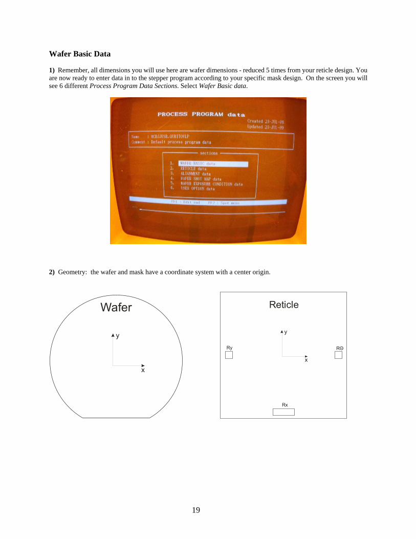
Wafer Basic Data 1) Remember, all dimensions you will use here are wafer dimensions - reduced 5 times from your reticle design. You are now ready to enter data in to the stepper program according to your specific mask design. On the screen you will see 6 different Process Program Data Sections. Select Wafer Basic data.
2) Geometry: the wafer and mask have a coordinate system with a center origin.
y
x
Wafer
y
x
Ry RΘ
Rx
Reticle
20
3) Example in the picture below is based on a 2” wafer. - Wafer Size is the diameter of the wafer in mm. Once field is selected, you can toggle different wafer sizes using spacebar on the keyboard. - Diameter option is the exposure area in mm. A small outer ring of the wafer is excluded from the exposure area, allowing for wafer handling. Six mm is the usual difference between Wafer size and Diameter. - Orientation Flat specifies which direction the wafer flat is on the stepper along with the flat size in microns - choose front and your specific wafer flat length. - Step pitch depends on your die size – it tells the stepper how far the wafer should move between exposures, in microns. - Map Layout tells the stepper how to center dies on the wafer. For example: choose Odd for both x and y if you want a die in the center of the wafer. Make them Even if you want to have intersection between dies in the center of the wafer. Ignore map offset and page 2 for the time being.
21
Reticle Data 1) Press PF2 to get to the Spot Menu. From the Spot Menu you can switch to the other Program Data Sections, or Check & Save, which verifies the program and saves it; Save which saves the program without verifying; No Save which exists without saving. Choose section named Reticle data. 2) On page 1, the first option is the reticle Name - type a name that will be used to refer to your reticle. This is the same name you will use in the Reticle Library Assignment Menu to tell machine which slot to take you reticle from. For the rest of page 1, keep the parameters shown in the picture below.
22
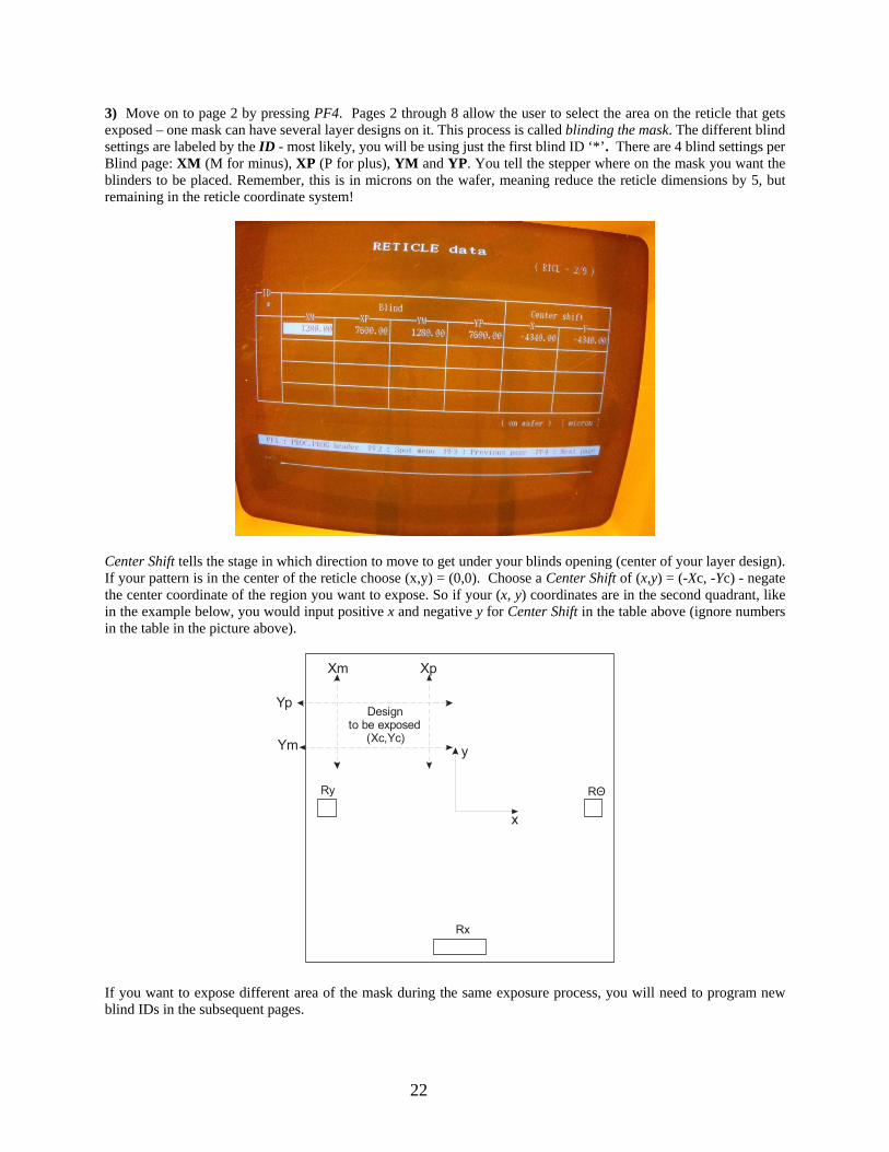
3) Move on to page 2 by pressing PF4. Pages 2 through 8 allow the user to select the area on the reticle that gets exposed – one mask can have several layer designs on it. This process is called blinding the mask. The different blind settings are labeled by the ID - most likely, you will be using just the first blind ID ‘*’. There are 4 blind settings per Blind page: XM (M for minus), XP (P for plus), YM and YP. You tell the stepper where on the mask you want the blinders to be placed. Remember, this is in microns on the wafer, meaning reduce the reticle dimensions by 5, but remaining in the reticle coordinate system!
Center Shift tells the stage in which direction to move to get under your blinds opening (center of your layer design). If your pattern is in the center of the reticle choose (x,y) = (0,0). Choose a Center Shift of (x,y) = (-Xc, -Yc) - negate the center coordinate of the region you want to expose. So if your (x, y) coordinates are in the second quadrant, like in the example below, you would input positive x and negative y for Center Shift in the table above (ignore numbers in the table in the picture above).
y
x
Ry RΘ
Rx
Xm Xp
Yp
Ym
Designto be exposed
(Xc,Yc)
If you want to expose different area of the mask during the same exposure process, you will need to program new blind IDs in the subsequent pages.
23
Alignment Data 1) Select the spot menu with PF2 and choose Alignment Data. Filling out this section is only important if you will be aligning to a pattern on the wafer i.e. you are programming second or higher level layers. If this is the first layer of your device, skip to the Wafer Shot Map Data section. Be sure your second (and higher) layer program has the same Wafer Basic Data information as the layer you are trying to align to. While there are many different options for aligning, we have seen consistent results when using the LSA sensor for the Search Alignment sequence and the FIA sensor for the g-EGA Alignment sequence. Please consult the Nikon’s official Reticle Design Guide and use the example reticle provided by WCAM (based on Prof. McDermott’s Group Mask) when designing your own mask. We recommend keeping the basic mark design, but creativity is allowed when positioning the marks on your die.
2) Choose Search and press enter. Here we are coarsely aligning to the WGA alignment marks (3 rows of rectangles in your alignment marks design). If you keep the basic shape of the marks the same, you should only change the mark positions on page 1: Y-T (x,y) and X (x,y). Units are microns and dimensions are on the wafer level (5x reduction from the reticle ones). In addition, note that the alignment marks coordinates are with respect to the center of the die.
24
3) Go to page 2 by pressing PF4. You should not have to change anything. Make sure that the Y-Theta search sequence is set to Normal. After you are done, press PF1 to return to the Alignment data menu.
4) Place your cursor over g-EGA and press enter. Here we are aligning to the FIA marks (9 lines in your alignment marks design). Once again, you need to enter in the correct locations of the X and Y alignment marks. The only other parameter that you should pay attention to on this page is Signal Profile—if your mark is reflective and on a reflective background (layer 1 and 2 are shiny) choose double; if either the background or the mark is dark, then choose single.
25
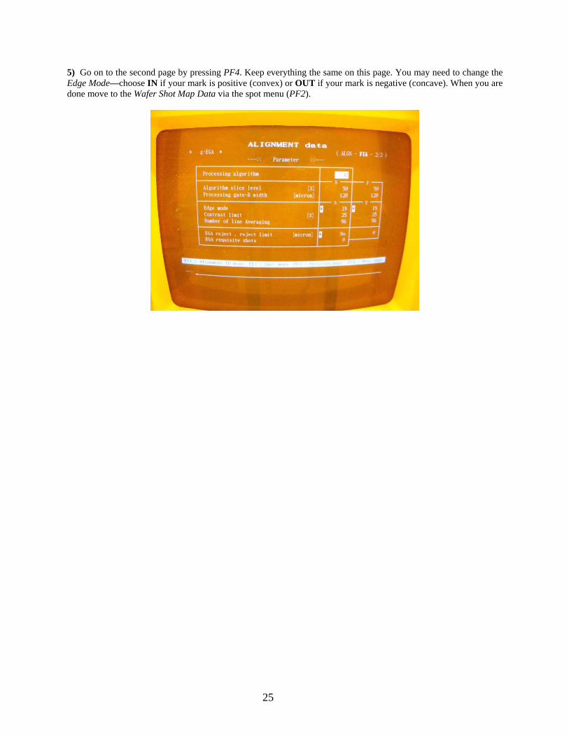
5) Go on to the second page by pressing PF4. Keep everything the same on this page. You may need to change the Edge Mode—choose IN if your mark is positive (convex) or OUT if your mark is negative (concave). When you are done move to the Wafer Shot Map Data via the spot menu (PF2).
26
Wafer Shot Map Data There are many things that can be done within this menu. This is a basic tutorial that should cover the most needed commands. For more details, please refer to the Nikon’s Reference Manual. On the left of the screen you see a grid with a population of *’s. Each ‘*’ represents a die on your wafer. The locations of each die are controlled by the Wafer Basic Data page you filled out earlier. You can navigate between the four Shot Map Modes by pressing PF3 or PF4. Navigate to the Alignment Shot mode if this program is aligning to an existing pattern on the wafer. This is where you tell the stepper which dies you want to use for alignment. - ‘?’ will give you information on the alignment marks available to you - ‘!’ will show you the current alignment mark assignments - ‘h’ will give you help screen
At this point you can move the cursor around the dies on your shot map. It is recommended to assign 3 dies for search alignment and at least 3 different dies for global alignment. You should always avoid the dies at the wafer edges in case they are not full dies and are missing alignment marks. To assign a search alignment shot, place the cursor over your die of choice, type ‘s’ and press enter. To place a global alignment shot move the cursor over your die of choice, type ‘g’ and press enter. A similar procedure is followed to assign different blind shots to individual dies in the Blind Shot section of this menu. Note: When you try to save the program, you may receive “no ‘s-shot’ specified” error. We aren’t sure what the origin of this error is. If the error occurs, place one or two more ‘s-shots’ until the error disappears.
27
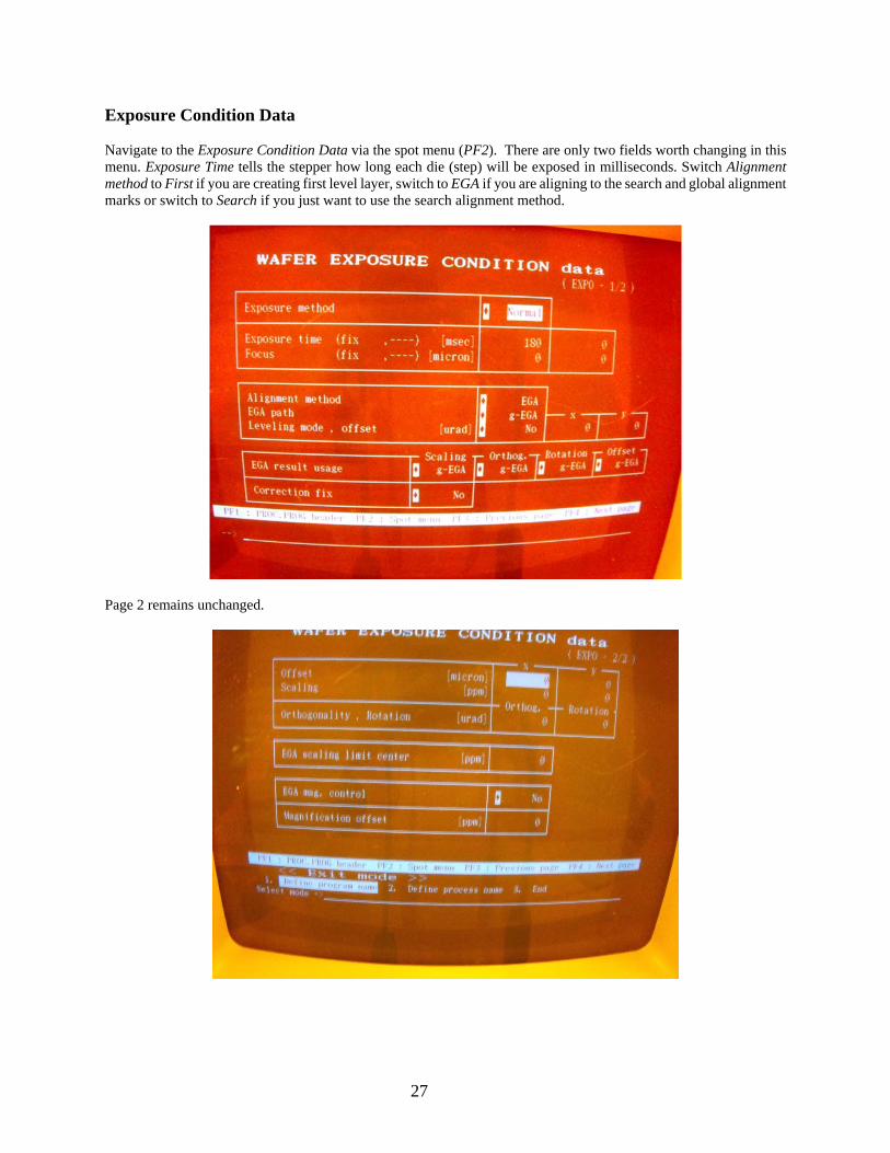
Exposure Condition Data Navigate to the Exposure Condition Data via the spot menu (PF2). There are only two fields worth changing in this menu. Exposure Time tells the stepper how long each die (step) will be exposed in milliseconds. Switch Alignment method to First if you are creating first level layer, switch to EGA if you are aligning to the search and global alignment marks or switch to Search if you just want to use the search alignment method.
Page 2 remains unchanged.
28
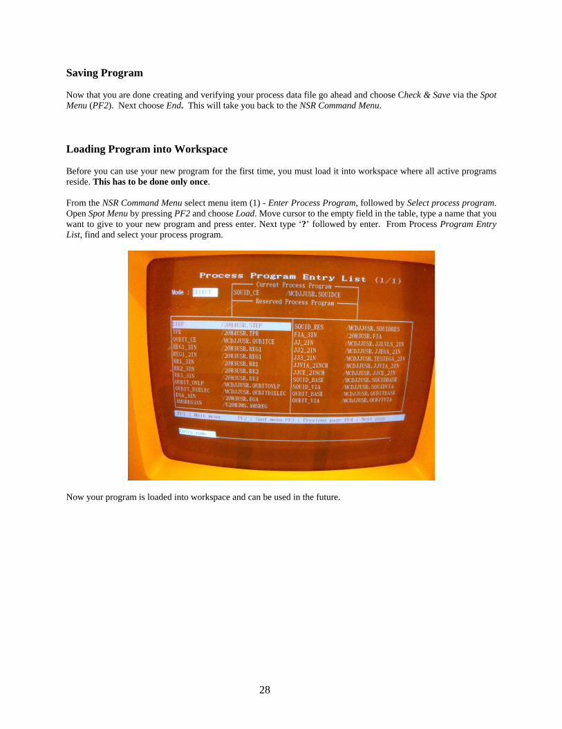
Saving Program Now that you are done creating and verifying your process data file go ahead and choose Check & Save via the Spot Menu (PF2). Next choose End. This will take you back to the NSR Command Menu. Loading Program into Workspace Before you can use your new program for the first time, you must load it into workspace where all active programs reside. This has to be done only once. From the NSR Command Menu select menu item (1) - Enter Process Program, followed by Select process program. Open Spot Menu by pressing PF2 and choose Load. Move cursor to the empty field in the table, type a name that you want to give to your new program and press enter. Next type ‘?’ followed by enter. From Process Program Entry List, find and select your process program.
Now your program is loaded into workspace and can be used in the future.