Page 1
1
Ni/Ni3C Core-Shell Nanochains and Its Magnetic
Properties: One-Step Synthesis at low temperature
Wei Zhou, † Lin He, ‡ Rongming Wang, † Kun Zheng,§ Lin Guo,*, † Chinping Chen*, ‡, Xiaodong Han*, §
and Ze Zhang§
†School of Materials Science and Engineering, School of Science, Beijing University of Aeronautics
and Astronautics, Beijing 100083, ‡ Department of Physics, Peking University, Beijing 100871 and
§Institute of Microstructure and Properties of Advanced Materials, Beijing University of
Technology,Beijing 100022, P. R. China
* To whom correspondence should be addressed. E-mail: [email protected] ; [email protected] ;
[email protected] .
RECEIVED DATE
†School of Materials Science and Engineering, Beijing University of Aeronautics and Astronautics.
‡Department of Physics, Peking University. §Institute of Microstructure and Properties of Advanced
Materials, Beijing University of Technology.
ABSTRACT One-dimensional Ni/Ni3C core-shell nanoball chains with an average diameter by
around 30 nm were synthesized by means of a mild chemical solution method using a soft template of
trioctylphosphineoxide (TOPO). It was revealed that the uniform Ni nanochains were capped with Ni3C
thin shells by about 1~4 nm in thickness and each Ni core consists of polygrains. The coercivity of the
core-shell nanochains is much enhanced (600 Oe at 5 K) and comparable with single Ni nanowires due
Page 2
2
to the one-dimensional shape anisotropy. Deriving from the distinctive structure of Ni core and Ni3C
shell, this architecture may possess a possible bi-functionality. This unique architecture is also useful
for the study on the magnetization reversal mechanism of one-dimensional magnetic nanostructure.
Introduction. Nanoscale magnetic materials such as Fe, Co, Ni have attracted much attention because
of their unique magnetic, catalytic and optical properties with promising applications in magnetic
sensors, high-density magnetic records, catalysts, etc.1–4 In addition, some of the basic issues about
magnetic and optical phenomena in one-dimensional systems have also been addressed with these
materials.4,5 Accordingly, a series of one-dimension (1D) nickel nanostructures including nanotubes,
nanowires, nanorods, nanochains and nanoarrays have been synthesized. 6–13
A variety of one-dimensional (1D) core-shell structures were prepared to enhance the multi-
functionality of these materials, and they have exhibited good characters in improving luminescent
efficiency, magnetic property and as field effect transistors.14–17 Many methods of preparation in high
temperature, including a laser ablation method, a high-temperature route and a carbothermal reduction
method, have been used to synthesize the core-shell nanomaterials.18–20 In addition, several solution-
based methods have emerged to generate nanocables having a core/shell structure with a metal core and
a sheath of different materials, including polymer, metal, semiconductor and insulator, at a relatively
low temperature.21–24 However, it remains a challenge to prepare the 1D Ni/Ni3C core-shell structure,
which has the metallic, soft ferromagnetic Ni in the core and the nonmagnetic Ni3C as the outer
protective sheath. Herein, we report a simple one-step chemical solution method to synthesize the core-
shell structured Ni/Ni3C nanochains at a low temperature. The structure, substructures and the
morphologies as well as the correlated magnetic properties of the nanochains were studied
systematically. The mechanisms and a simplified model of formation for the Ni/Ni3C nanochains were
proposed.
Page 3
3
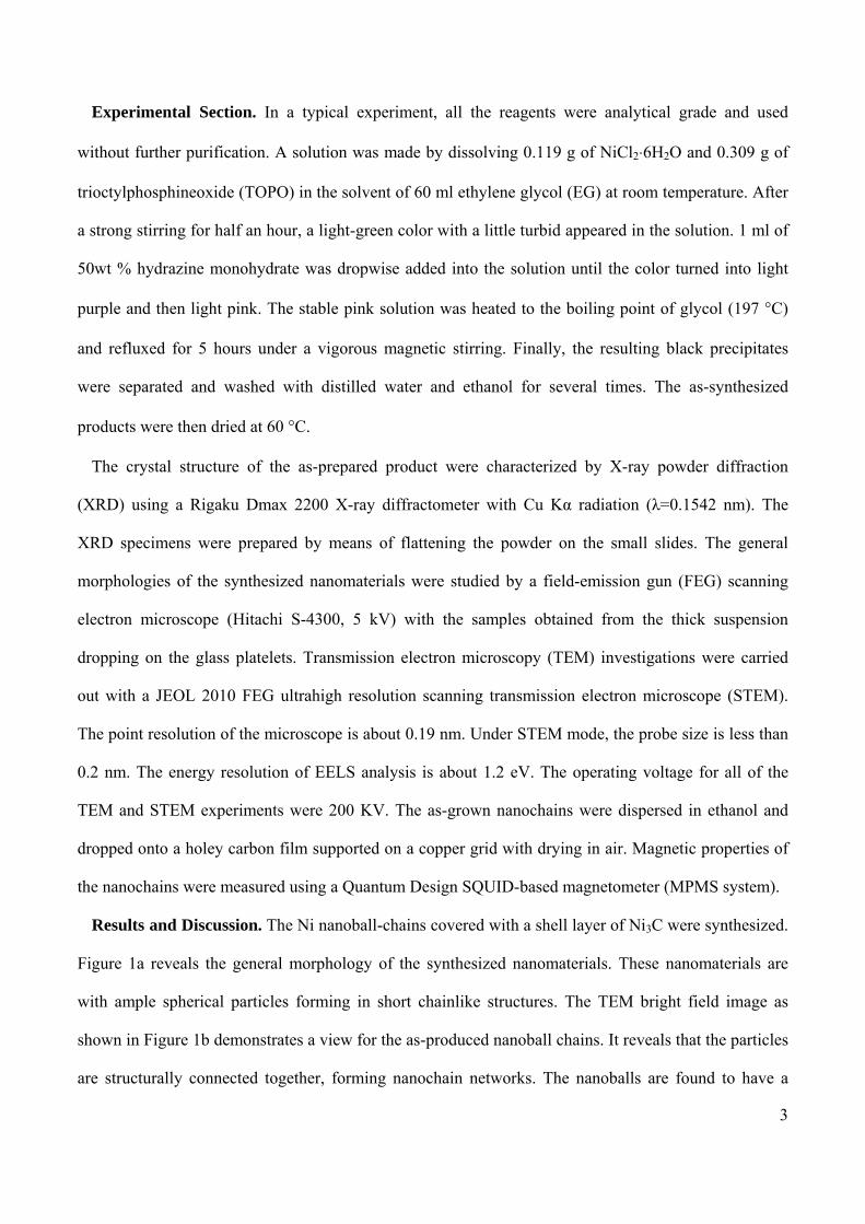
Experimental Section. In a typical experiment, all the reagents were analytical grade and used
without further purification. A solution was made by dissolving 0.119 g of NiCl2⋅6H2O and 0.309 g of
trioctylphosphineoxide (TOPO) in the solvent of 60 ml ethylene glycol (EG) at room temperature. After
a strong stirring for half an hour, a light-green color with a little turbid appeared in the solution. 1 ml of
50wt % hydrazine monohydrate was dropwise added into the solution until the color turned into light
purple and then light pink. The stable pink solution was heated to the boiling point of glycol (197 °C)
and refluxed for 5 hours under a vigorous magnetic stirring. Finally, the resulting black precipitates
were separated and washed with distilled water and ethanol for several times. The as-synthesized
products were then dried at 60 °C.
The crystal structure of the as-prepared product were characterized by X-ray powder diffraction
(XRD) using a Rigaku Dmax 2200 X-ray diffractometer with Cu Kα radiation (λ=0.1542 nm). The
XRD specimens were prepared by means of flattening the powder on the small slides. The general
morphologies of the synthesized nanomaterials were studied by a field-emission gun (FEG) scanning
electron microscope (Hitachi S-4300, 5 kV) with the samples obtained from the thick suspension
dropping on the glass platelets. Transmission electron microscopy (TEM) investigations were carried
out with a JEOL 2010 FEG ultrahigh resolution scanning transmission electron microscope (STEM).
The point resolution of the microscope is about 0.19 nm. Under STEM mode, the probe size is less than
0.2 nm. The energy resolution of EELS analysis is about 1.2 eV. The operating voltage for all of the
TEM and STEM experiments were 200 KV. The as-grown nanochains were dispersed in ethanol and
dropped onto a holey carbon film supported on a copper grid with drying in air. Magnetic properties of
the nanochains were measured using a Quantum Design SQUID-based magnetometer (MPMS system).
Results and Discussion. The Ni nanoball-chains covered with a shell layer of Ni3C were synthesized.
Figure 1a reveals the general morphology of the synthesized nanomaterials. These nanomaterials are
with ample spherical particles forming in short chainlike structures. The TEM bright field image as
shown in Figure 1b demonstrates a view for the as-produced nanoball chains. It reveals that the particles
are structurally connected together, forming nanochain networks. The nanoballs are found to have a
Page 4
4
uniform size with the diameter of 30±10 nm. Figure 1c shows a high magnification TEM bright field
image for a single nanoball which reveals clearly a core-shell structure. The subsequent sections will
demonstrate that this core-shell nanoball consists of a Ni core and a Ni3C shell of 1~4 nm in thickness.
Figure 1d is a selected area electron diffraction (SAED) pattern taken from Figure 1b. The diffraction
rings can be indexed with the face centered cubic (FCC) Ni and the rhombohedra (RH) Ni3C as shown
in Figure 1d. The X-ray diffraction (XRD) pattern shown in Figure 1e confirms the above results. The
main diffraction peaks marked with diamonds correspond to reflections of face-centered cubic (FCC) Ni
with lattice parameter a = 0.3514 nm (JCPDS 04-0850). The other peaks marked with triangles can be
assigned to be (110), (006), (113), (116), (300) and (119) planes of Ni3C (JCPDS 77-0194). The peak of
(111)Ni overlays with the peak of (113)Ni3C. Both of the SAED pattern and the XRD result show well
crystalline characters of Ni and Ni3C phases.
Figure 1. (a) SEM overview image of Ni/Ni3C nanochains. (b) Bright field TEM image of the chainlike
network. (c) High magnification TEM image of a single nanoball from the top of a chain, showing the
30 40 50 60 70 80
(22
0)
(20
0)
Inte
nsity
(a.u
.)
2θ (deg.)
(11
6)
(30
0)
(11
9)
(00
6) (
110)
(1
13)
e
(111
)
NiNi3C
Page 5
5
core-shell structure. (d) SAED pattern from several nanoballs of Figure 2b. (e) XRD pattern of the as-
grown product.
The structure and substructures of the Ni/Ni3C nanoball chains were further studied at atomic scale.
Figure 2a shows a low magnification image of several connected nanoballs. Figure 2b is a HRTEM
image taken from the cyan framed region of Figure 2a. The elongated nanoball consists of a core about
10 nm in diameter and a shell about 4nm in thickness. A Fast Fourier Transformation (FFT) pattern,
shown as Figure 2c, is arranged at the right bottom in Figure 2b. It shows a well crystalline feature of
the core-shell structure with the three sets of diffraction patterns. The diffraction spots marked as 1, 2
and 3 in Figure 2c for the FFT diffraction pattern correspond to the lattice zones 1, 2 and 3 in Figure 2b,
respectively. The diffraction spots 1 and 2 can be assigned to (110)Ni3C, while 3 to (111)Ni.
Figure 2. (a) HRTEM image of a particle at the tip of a chain. (b) Magnified image of the cyan square
in Figure 2a. (c) FFT pattern corresponds to Figure 2b. The diffraction spots 1, 2 and 3 correspond to
the lattices zone 1, 2 and 3 in Figure 2b. (d) Enlarged part of the blue square in Figure 2a.
As revealed in Figure 2b, the shell’s lattice zone “1” alters its orientation to be along lattice zone “2”
to match the inner Ni lattice structure, therefore, to minimize the lattice mismatch energy. Figure 2d is a
Page 6
6
magnified HRTEM image of the blue-framed region in Figure 2a taken near the connecting region of
two contiguous Ni nanoparticles. Obviously, both of the core and the shell’s lattice fringes
consecutively cross the two nanoparticles without interruption by an apparent boundary. The blue lines
draw the lattices of Ni3C shell which show the varying of the crystalline orientation. This indicates that
the Ni3C shell grew on the surface of Ni core by an epitaxial way in which, due to the ball-shaped Ni
core, the Ni3C shell appeared to be with a polycrystalline structure to minimize the localized lattice-
mismatch energy (Please note that even in the single crystalline region of Ni core, the Ni3C still appears
as polycrystalline feature). This suggests a post-growth process of the Ni3C shell over the Ni
polycrystalline core.
Figure 3. (a) TEM image and the corresponding EDS elemental maps of a nanoball, revealing the
spatial distribution of (b) nickel and (c) carbon elements. (d) TEM image for the scanning region under
the EELS analysis. (e) EELS spectrum showing C-K edge and Ni-L edge.
The shell component of the nanoball is demonstrated to be Ni3C by energy dispersion spectroscopy
(EDS) and electron energy loss spectroscopy (EELS). Figure 3a is an image for a nanoparticle with the
200 400 600 800 1000-50000
0
50000
100000
150000
200000
250000
300000
350000
Ni-L2,3
C-K
Cou
nts
Energy Loss (eV)
e
b
Ni -L
c
C -K
a
5nm
d
50nm
Page 7
7
Ni/Ni3C core-shell structure. Figures 3b and 3c show EDS elemental mapping scan results of the
nanoball taken from the framed region of Figure 3a for elements Ni and C, respectively. Figure 3c
shows a clear carbon shell structure giving the distribution of C element. To reveal the carbon bonding
structure in the shell, EELS analysis was conducted. Figure 3d shows the region within which the
spectrum was taken, and Figure 3e shows the corresponding EELS spectrum. The carbon K-edge and
nickel L-edge are revealed in the spectrum at 291 eV and 855 eV, respectively. The carbon K-edge
shows strong and sharp δ bond character 25,26 which is attributable to the Ni-C bonds. It has the similar
feature with the diamond structure without any trace of π bonds. 25,26 The X-ray results and the
polycrystalline diffraction rings in Figure 1 excludes the possibility of the out-shell structure being
diamond-like carbon. The half-width of the K-edge peak is sharp and narrow. It indicates an ordered
structure of carbon and a constant distance of the C-Ni bonding.
Page 8
8
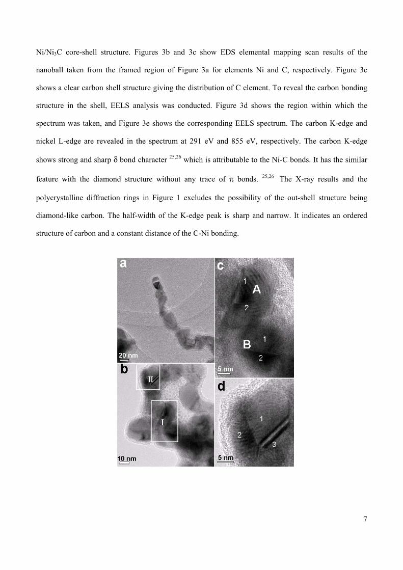
Figure 4. (a) A typical core-shell Ni nanochains. (b) HRTEM image showing the core-shell structure of
the nanochain and the polycrystalline feature of the Ni cores. (c) An enlarged image for region I in (b).
(d) An enlarged image for region II in (b).
Following the above microstructural analysis, we finally clarify most Ni core is with a polycrystalline
feature. Figure 4a shows a typical core-shell nanochain. Figure 4b reveals the polycrystalline features of
the Ni core. Figures 4c and 4d are the images with higher resolution for the framed areas I and II in
Figure 4b, respectively. Figure 4c shows two Ni nanoballs (A and B) connects with each other inside a
common Ni3C shell. Both of them consist of two nanograins, marked as 1 and 2. On the other hand, the
nanoball in Figure 4d consists of three nanograins, marked as 1, 2, and 3, inside a common Ni3C shell. It
can be concluded that each shell of the nanoball contains 1~3 Ni monocrystal grains. According to the
characterizations by the EDS, EELS, and XRD analyses along with the TEM and HREM observations,
it is concluded that the nanochains are with the Ni/Ni3C core-shell structures. The inner Ni cores, each
of which consists of 1~3 nanograins, are in connection with each other structurally with a common Ni3C
shell layer grown in the outer surface.
The temperature dependent magnetization, M(T), curves shown in Figure 5(a) were measured by the
zero-field-cooling and field-cooling (ZFC and FC) modes from 5 K to 380 K. To perform the ZFC
measurement, the procedure was to cool the sample under zero applied field down to 5 K, and then
applied a field of 90 Oe for data collection in the warming process. For the FC curve, the procedure was
the same as in the ZFC measurement, except that the sample was cooled with the presence of an applied
magnetic field of 20 kOe. These two curves separate widely from each other, indicating the presence of
a magnetic anisotropy barrier. The blocking temperature corresponding to this anisotropy is much
higher than 380 K. Interestingly, for a comparison with the result from the pure Ni nanochain with a
free surface,13,27 the freezing peak at T ~ 13 K attributed to the surface spin glass state is completely
suppressed with the present Ni/Ni3C sample.27 This indicates that the thin Ni3C shell layer serves not
only as a chemically inner encapsulation layer but also as a magnetically surface modification layer.
Page 9
9
Figure 5b shows the M(H) data measured at 5 K, 100 K and 300 K. The saturation magnetization
determined in the high field region at 300 K is 35.4 emu/g, ~0.37 µB per Ni atom. It accounts for 61% of
the corresponding bulk value, ~ 0.6 06 µB/Ni. The reduction of the saturation magnetization is most
likely arising from the existence of the nonferromagnetic Ni3C 28 shell layer. By assuming a spherical
core-shell structure with an average outer diameter of 30 nm, the reduction in the observed saturation
magnetization is attributable to an averaged Ni3C shell thickness of about 2.3 nm. This is reasonably
consistent with the result of the shell thickness, 1~4 nm, observed by the HRTEM investigation.
Figure 5. (a) ZFC and FC magnetization, M(T), measured with the applied field of 90 Oe. (b) M(H) data
measured at 5 K, 100K and 300K. The inset shows the open hysteresis in the low field region.
With decreasing temperature, the saturation magnetization increases slightly, as shown in Figure 5b. An
open hysteresis loop was observed in the low field region. The coercivity field, HC, at 5 K was
determined as 600 Oe, which is similar to the result, ~ 600 Oe, obtained for the Ni nanowires with the
diameters ranging from 40 to 100 nm and lengths up to 5 µm at T = 5 K.29 The large coercivity is not
unexpected due to the one-dimensional shape of the samples. The magnetization reversal mechanism in
the present nanochain structure can be described by the fanning mode of magnetization reversal
according to the “chain of spheres” model.30 This is reasonable due to the fact that the diameter of the
sphere, 25.4 nm (30 nm – 4.6 nm), is comparable to the coherence length of Ni, ~ 25 nm. With the
fanning mode, the HC measured along the chain is expressed as,
(1) )46( n3, LKR
H nnC −= μ
0 100 200 300 4000
10
20
ZFCM (
emu
/ g )
T (K)
FCa
-10000 0 10000
-40
0
40
-800 0 800
-20
0
20
5K 100K 300K
M (
emu
/ g )
H (Oe)
b
H (Oe)
Page 10
10
where μ and R are the dipole moment and the diameter of each sphere. The expression in the
parenthesis takes into account for the dipolar interaction between the magnetic spheres in the chain
based on the assumption of fanning mode. In particular, Kn accounts for the dipolar interaction between
each every pair of the magnetic particles, and Ln, between each odd-numbered and even-numbered pairs.
The number, n, is for the sphere numbering in the chain.30 This model considers the low temperature
property without accounting for the thermal activation effect. The term μ/R3 can be expressed, using
saturation magnetization per unit volume MS, as μ/R3 = (π/6) MS. Thus, by using the experimental value
of MS, the density of bulk Ni and assuming n =12, we obtain the values of HC as 485 Oe. By taking into
account the correction factor for the randomly oriented effect in a powdered sample, the value of the
coercivity is modeified as H’C ~ 1.1HC = 534 Oe. This agrees with our experimental result, ~ 600 Oe,
within 11%. The remanent magnetization at 5 K is about 19 emu/g. The corresponding remanent ratio is
0.475. This is in agreement with the prediction of fanning model, ~ 0.5, for the randomly oriented
particles within 5%. With increasing temperature, both the coercivity and remanent magnetization
decrease, as shown in the inset of Figure 5b, due to the thermal activation effect.31 The coercivity and
remanent magnetization are 390 Oe and 15 emu/g at 100 K, respectively. They become 217 Oe and 10.5
emu/g at 300 K.
Normally, Ni3C is obtained by physics methods with the conditions of high temperature,32 and high
pressure, such as mechanical alloying,28,33 C-ion implantation into Ni,34 and reaction between Ni and
amorphous C films.35 Recently, mild chemical solution methods have been applied to synthesize
nanosized nickel carbide. For example, Leng et al. prepared pure Ni3C nanoparticles by thermal
decomposition in solution at 529 K.36 However, most Ni-based nanomaterials with the core-shell
structure were reported with Ni/C 37,38,39 or Ni3C/C 39,40 nanoparticles. To our best knowledge, the
core-shell Ni/Ni3C nanochain structure has never been reported before. More significantly, in our
present case, the Ni/Ni3C core-shell architecture was obtained by a one-step chemical solution method
below 473 K.
Page 11
11
The formation of the Ni/Ni3C core-shell structure could be explained by the following simplified
model and process. First, as shown in Figures 6a, Ni particles form in several minutes in the solution
with the presence of TOPO (C24H51OP) at the boiling point of glycol. It has been known that TOPO is a
surface modifying agent for preparing Ni nanomaterials.9,41 Under the surface modification effect of
TOPO and the magnetic dipolar interaction of the Ni grains, the one-dimensional nanochain structure
was evolved rapidly as illustrated in Figure 6b.
Figure 6. Illustration of the formation of the Ni/Ni3C core-shell nanochain. (a) the formation of Ni
particles in TOPO solution; (b) the formation of nano Ni-chain covered with TOPO is shown at the top.
An enlarged cross-sectional view is shown at the bottom. Catalyzed by Ni and come from TOPO, the
free active carbon atoms started to form on the surface of nano Ni-chain, the red-snaked arrows indicate
the catalyzation process; (c) the carbon atoms diffused into the Ni lattice and naturally introduced a
concentration gradient shell of carbon-Ni. The top and bottom sets are the side view and the enlarged
cross-sectional view, respectively. The black arrows indicate the diffusion process; (d) the formation of
Ni3C on the Ni surface and core-shell structure of Ni3C-Ni. The top and bottom sets are the side-view
and enlarged cross-sectional view, respectively.
Page 12
12
Meanwhile, deriving from electrostatic interactions, TOPO molecules were adsorbed on the surface of
the Ni chains. Similar to the formation of carbon by their low-temperature cleavage of alkanes,42 the
small Ni particles catalyze the formation of active carbon from the organic molecules (TOPO) on their
surfaces (Figure 6b).36,43 As the restricted forming rate of active C atoms at the temperature of 470K
(the boiling point of EG), the formation of Ni3C (Figure 6d) is posterior to that of Ni chains (Figure 6b).
Then, the active carbon atoms gradually diffuse from the surfaces into Ni nanochains driven by the
concentration gradient of the carbon (Figure 6c), 36,44,45 forming the Ni3C interstitial compound. The
prior-formed Ni3C shells were likely to prevent the formation of additional carbide by stopping the
contact of the Ni atoms and the active carbon atoms.44,45 This process made an intact Ni-core in the
centre and formed this core-shell structure(Figure 6d), finally.
In summary, the Ni/Ni3C core-shell nanochains were formed with the surface modification of
trioctylphosphineoxide (TOPO) at a low temperature (below 473K). This unique architecture may play
bi-functionality deriving from the magnetic Ni core and the non-magnetic and oxidation resistant Ni3C
shell. The Ni3C layer was formed by the active carbon atoms diffusing into the Ni particles on the
surfaces. The mechanism could be used to guide the synthesis of similar core-shell nanomaterials. By
magnetic measurements, the saturation magnetization of the nanochains is reduced sharply (accounting
for 61% of the corresponding bulk value) due to the presence of the nonmagnetic Ni3C. However, the
coercivity is much enhanced (600 Oe at 5K) attributed to the one-dimensional morphology of the
sample. Both of the coercivity and the remanent magnetization are in good agreement with the
description of the fanning model at a low temperature. This unique architecture is useful to study the
magnetization reversal mechanism for understanding the basic correlated magnetic physics.
Acknowledgment. Authors acknowledge the support from the National Natural Science Foundation
of China (20673009, 50725208 & 50671003), SRFDP-20060006005, the program for New Century
Excellent Talents in University (NCET-04-0164 & NCET-05009015299701), the National Basic
Page 13
13
Research Program of China (2007CB935400 & 2006CB932300) and XDHAN thanks Beijing Education
Committee Key Program (Beijing Nature Science Foundation Key Program)
FIGURE CAPTIONS
Figure 1. (a) SEM overview image of Ni/Ni3C nanochains. (b) Bright field TEM image of the chainlike
network. (c) High magnification TEM image of a single nanoball from the top of a chain, showing the
core-shell structure. (d) SAED pattern from several nanoballs of Figure 2b. (e) XRD pattern of the as-
grown product.
Figure 2. (a) HRTEM image of a particle at the tip of a chain. (b) Magnified image of the cyan square
in Figure 2a. (c) FFT pattern corresponds to Figure 2b. The diffraction spots 1, 2 and 3 correspond to
the lattices zone 1, 2 and 3 in Figure 2b. (d) Enlarged part of the blue square in Figure 2a.
Figure 3. (a) TEM image and the corresponding EDS elemental maps of a nanoball, revealing the
spatial distribution of (b) nickel and (c) carbon elements. (d) TEM image for the scanning region under
the EELS analysis. (e) EELS spectrum showing C-K edge and Ni-L edge.
Figure 4. (a) A typical core-shell Ni nanochains. (b) HRTEM image showing the core-shell structure of
the nanochain and the polycrystalline feature of the Ni cores. (c) An enlarged image for region I in (b).
(d) An enlarged image for region II in (b).
Figure 5. (a) ZFC and FC magnetization, M(T), measured with the applied field of 90 Oe. (b) M(H) data
measured at 5 K, 100K and 300K. The inset shows the open hysteresis in the low field region.
Figure 6. Illustration of the formation of the Ni/Ni3C core-shell nanochain. (a) the formation of Ni
particles in TOPO solution; (b) the formation of nano Ni-chain covered with TOPO is shown at the top.
An enlarged cross-sectional view is shown at the bottom. Catalyzed by Ni and come from TOPO, the
free active carbon atoms started to form on the surface of nano Ni-chain, the red-snaked arrows indicate
the catalyzation process; (c) the carbon atoms diffused into the Ni lattice and naturally introduced a
concentration gradient shell of carbon-Ni. The top and bottom sets are the side view and the enlarged
Page 14
14
cross-sectional view, respectively. The black arrows indicate the diffusion process; (d) the formation of
Ni3C on the Ni surface and core-shell structure of Ni3C-Ni. The top and bottom sets are the side-view
and enlarged cross-sectional view, respectively.
References
(1) Aign T.; Meyer P.; Lemerle S.; Jamet J. P.; Ferré J.; Mathet V.; Chappert C.; Gierak J.; Vieu C.;
Rousseaux F.; Launois H.; Bernas H. Phys. Rev. Lett. 1998, 81, 5656–5659.
(2) Todorovic M.; Schultz S.; Wong J.; Scherer A. Appl. Phys. Lett. 1999, 74, 2516–2518.
(3) Huang S. X.; Fischer D. A.; Gland J. L. J. Phys. Chem. 1996, 100, 10223–10234.
(4) Sauer G.; Brehm G.; Schneider S.; Graener H.; Seifert G.; Nielsch K.; Choi J.; GÖring P.; GÖsele
U.; Miclea P.; Wehrspohn R. B. Appl. Phys. Lett. 2006, 88, 023106.
(5) Burton J. D.; Sabirianov R.F.; Jaswal S.S.; Tsymbal E.Y. Phys. Rev. Lett. 2006, 97, 077204.
(6) Tanase M.; Bauer L. A.; Hultgren A.; Silevitch D. M.; Sun L.; Reich D. H.; Searson P. C.; Meyer
G. J. Nano Lett. 2001, 1, 155–158.
(7) Pan H.; Liu B.; Yi J.; Poh C.; Lim S.; Ding J.; Feng Y.; Huan C. H. A.; Lin J. J. Phys. Chem. B
2005, 109, 3094–3098.
(8) Chu S. Z.; Wada K.; Inoue S.; Todoroki S.; Takahashi Y. K.; Hono K. Chem. Mater. 2002, 14,
4595–4602.
(9) Cordente N.; Respaud M.; Senocq F.; Casanove M.-J.; Amiens C.; Chaudret B. Nano Lett. 2001, 1,
565–568.
(10) Knez M.; Bittner A. M.; Boes F.; Wege C.; Jeske H.; Maib E.; Kern K. Nano Lett. 2003, 3, 1079–
1082.
Page 15
15
(11) Liu Z. P.; Li S.; Yang Y.; Peng S.; Hu Z. K.; Qian Y. T. Adv. Mater. 2003, 15, 1946–1948.
(12) Niu H.; Chen Q.; Ning M.; Jia Y.; Wang X. J. Phys. Chem. B 2004, 108, 3996–3999.
(13) Liu C. M.; Guo L.; Wang R. M.; Deng Y.; Xu H. B.; Yang S. H. Chem. Commun. 2004, 2726–
2727.
(14) Bu W.; Hua Z.; Chen H.; Shi J. J. Phys. Chem. B 2005, 109, 14461–14464.
(15) Wang Z.; Lu Q.; Kong M.; Zhang L. Chem. Eur. J. 2007, 13, 1463–1470.
(16) Zhang D.; Liu Z.; Han S.; Li C.; Lei B.; Stewart M. P.; Tour J. M.; Zhou C. Nano Lett. 2004, 4,
2151–2155.
(17) Xiang J.; Lu W.; Hu Y.; Wu Y.; Yan H.; Lieber C. M. Nature 2006, 441, 489–493.
(18) Shi W. S.; Peng H. Y.; Xu L.; Wang N.; Tang Y. H. H.; Lee S. T. Adv. Mater. 2000, 12, 1927–
1930.
(19) Zhang Y.; Suenaga K.; Colliex C.; Lijima S. Science 1998, 281, 973–975.
(20) Zhang L. D.; Meng G. W.; Phillipp F. Mater. Sci. Eng. A 1998, 286, 34–38.
(21) Luo L. -B.; Yu S. -H.; Qian H. -S.; Zhou T. J. Am. Chem. Soc. 2005, 127, 2822–2823.
(22) Wang Q., Wang G., Han X., Wang X., Hou J. G. J. Phys. Chem. B 2005, 109, 23326–23329.
(23) Yin Y.; Lu Y.; Sun Y.; Xia Y. Nano Lett. 2002, 2, 427–430.
(24) Ma D.; Zhang M.; Xi G.; Zhang J.; Qian Y. Inorg. Chem. 2006, 45, 4845–4849.
(25) Yuan J.; Brown L.M. Micron 2000, 31, 515–525.
(26) http://people.ccmr.cornell.edu/~davidm/WEELS/Frames/C_frames.htm
Page 16
16
(27) He L.; Zheng W. Z.; Zhou W.; Du H. L.; Chen C. P. ; Guo L. J. Phys.: Condens. Matter. 2007,
19, 036216.
(28) Yue L. P.; Sabiryanov R.; Kirkpatrick E. M.; Leslie-Pelecky D. L. Phys. Rev. B 2000, 62, 8969–
8975.
(29) Wernsdorfer W.; Hasselbach K.; Benoit A.; Barbara B.; Doudin B.; Meier J.; Ansermet J.; Mailly
D. Phys. Rev. B 1997, 55, 11552–11559.
(30) Jacobs I. S.; Bean C. P. Phys, Rev. 1955, 100, 1060–1067.
(31) He L.; Chen C. P. Phys. Rev. B 2007, 75, 184424.
(32) Nagakura S. J. Phys. Soc. Jpn. 1957, 12, 482–494.
(33) Tokomitsu K. Mater. Sci. Forum 1997, 127, 235–238.
(34) Wang J.; Wu X. F.; Liu B. X. Acta Metall. Mater. 1992, 40, 1417–1420.
(35) Sinharoy S.; Smith M. A.; Levenson L. L. Surf. Sci. 1978, 72, 710–718.
(36) Leng Y.; Shao H.; Wang Y.; Suzuki M.; Li X. J. Nanosci. Nanotech. 2006, 6, 1–6.
(37) Zhu G. X.; Wei X. W.; Jiang S. J. Mater. Chem. 2007, 17, 2301–2306.
(38) Sun X.C.; L. Dong X. Mater. Res. Bull. 2002, 37, 991-1004.
(39) Sun X.C.; Gutierrez A.; Yacaman M. J.; Dong X. L.; Jin S. R. Mater. Sci. Engeer. A 2000, 286,
157–160.
(40) Nishijo J.; Okabe C.; Oishi O.; Nishi N. Carbon 2006, 44, 2943–2949.
(41) Cordente N.; Amiens C.; Chaudret B.; Respaud M.; Senocq F.; Casanove M.-J. J. Appl. Phys.
2003, 94, 6358–6365.
(42) Davis S. C.; Severson S. J.; Klabunde K. J. J. Am. Chem. Soc. 1981, 103, 3024–3029.
Page 17
17
(43) Hooker P.; Tan B. J.; Klabunde K. J.; Suib S. Chem. Mater. 1991, 3, 947–952.
(44) Zeng Z.; Natesan K. Chem. Mater. 2003, 15, 872–878.
(45) Ducati C.; Alexandrou I.; Chhowalla M.; Robertson J.; Amaratunga G. A. J. J. Appl. Phys. 2004,
95, 6387–6391.
SYNOPSIS TOC
One-dimensional Ni/Ni3C core-shell nanochains were synthesized by a one-step chemical solution
method using a soft template of trioctylphosphineoxide (TOPO) at a low temperature (below 473K).
This special structure is ideal to protect Ni nanochains from oxidation and to study the magnetization
reversal mechanism.