105
Applied Economics Office Engineering Laboratory Gaithersburg, MD 20899 U. S. Department of Commerce National Institute of Standards and Technology NIST Special Publication 1122

Applied Economics Office
Engineering Laboratory
Gaithersburg, MD 20899
U. S. Department of Commerce National Institute of Standards and Technology
NIST Special Publication 1122


U.S. Department of Commerce National Institute of Standards and
Technology
Proposed UNIFORMAT II Classification of Bridge Elements
Muthiah Kasi and Robert E. Chapman
Sponsored by:
National Institute of Standards and Technology
Engineering Laboratory
May 2011
U.S. DEPARTMENT OF COMMERCE
Gary Locke, Secretary
NATIONAL INSTITUTE OF STANDARDS AND TECHNOLOGY
Patrick D. Gallagher, Director
NIST Special Publication 1122
Applied Economics Office Engineering Laboratory
Gaithersburg, Maryland 20899-8603


iii
Abstract
This report presents a proposed UNIFORMAT II classification of bridge elements.
Elemental classifications differ from traditional product-related classifications because
their core concept is an element that performs a given function, regardless of the design
specification, construction method, or materials used. The proposed classification
represents a major revision and restructuring of ASTM Standard Classification E 2103, a
bridge-related standard classification first issued by ASTM in 2000. The original bridge
classification, E 2103, differed from the UNIFORMAT II elemental classification
hierarchy in several ways which limited its applicability. The major revisions to E 2103
described in this report will promote its relevance, understanding, and acceptance in the
bridge industry. Once approved and reissued by ASTM, the UNIFORMAT II Standard
Classification of Bridge Elements, E 2103, will provide the basis for a comprehensive
data set of bridge-related costs that will enable public and private decision makers to
choose more cost-effective solutions for the design and construction of new bridges and
the maintenance and repair of existing bridges across the Nation.
A set of alphanumeric designators for the proposed multi-level bridge classification is
included. Because many users are interested in constructing databases for use in cost
analyses associated with project planning, design, construction, maintenance and repair,
and condition assessment, alphanumeric designators provide the basis for compiling,
organizing, and referencing cost data.
This report also includes a proposed list of sub-elements for bridges. The UNIFORMAT
II hierarchy consists of three levels: Level 1, Major Group Elements; Level 2, Group
Elements; and Level 3, Individual Elements. Thus, the core concept of an element
resides at Level 3. However, because elements are major components of a constructed
entity, there is often ambiguity of what exactly is included in an Individual Element and
what should be rightfully excluded from it. Because sub-elements can be tied into a work
breakdown structure, they significantly enhance the usefulness of an elemental
classification across all project participants throughout the lifecycle of bridges and other
constructed entities.
Keywords:
Bridges; construction; cost estimation; economic analysis; functional elements; life-cycle
cost; risk analysis; standards; UNIFORMAT II; value engineering

iv
v
Preface
This report produces a proposed classification of bridge elements that will provide the
basis for a standard classification of bridge elements to be issued by ASTM International.
The material presented in this report will also provide the basis for a comprehensive data
set of bridge-related costs that will enable public and private decision makers to choose
more cost-effective solutions for the design and construction of new bridges and the
maintenance and repair of existing bridges across the Nation. The intended audience is
the National Institute of Standards and Technology, the bridge industry, standards and
codes developers, the American Association of State Highway and Transportation
Officials, the American Society of Civil Engineers, and other construction industry
stakeholders interested in improving interdisciplinary communications and in reducing
the costs of designing, constructing, and maintaining the Nation’s physical infrastructure.
Disclaimer
Certain trade names and company products are mentioned in the text in order to
adequately specify the technical procedures and equipment used. In no case does such
identification imply recommendation or endorsement by the National Institute of
Standards and Technology, nor does it imply that the products are necessarily the best
available for the purpose.
Disclaimer Regarding Non-Metrics Units
The policy of the National Institute of Standards and Technology is to use metric units in
all of its published materials. Because this report is intended for the U.S. construction
industry that uses U.S. customary units, it is more practical and less confusing to include
U.S. customary units as well as metric units. Measurement values in this report are
therefore stated in metric units first, followed by the corresponding values in U.S.
customary units within parentheses.
Cover Photographs Credits
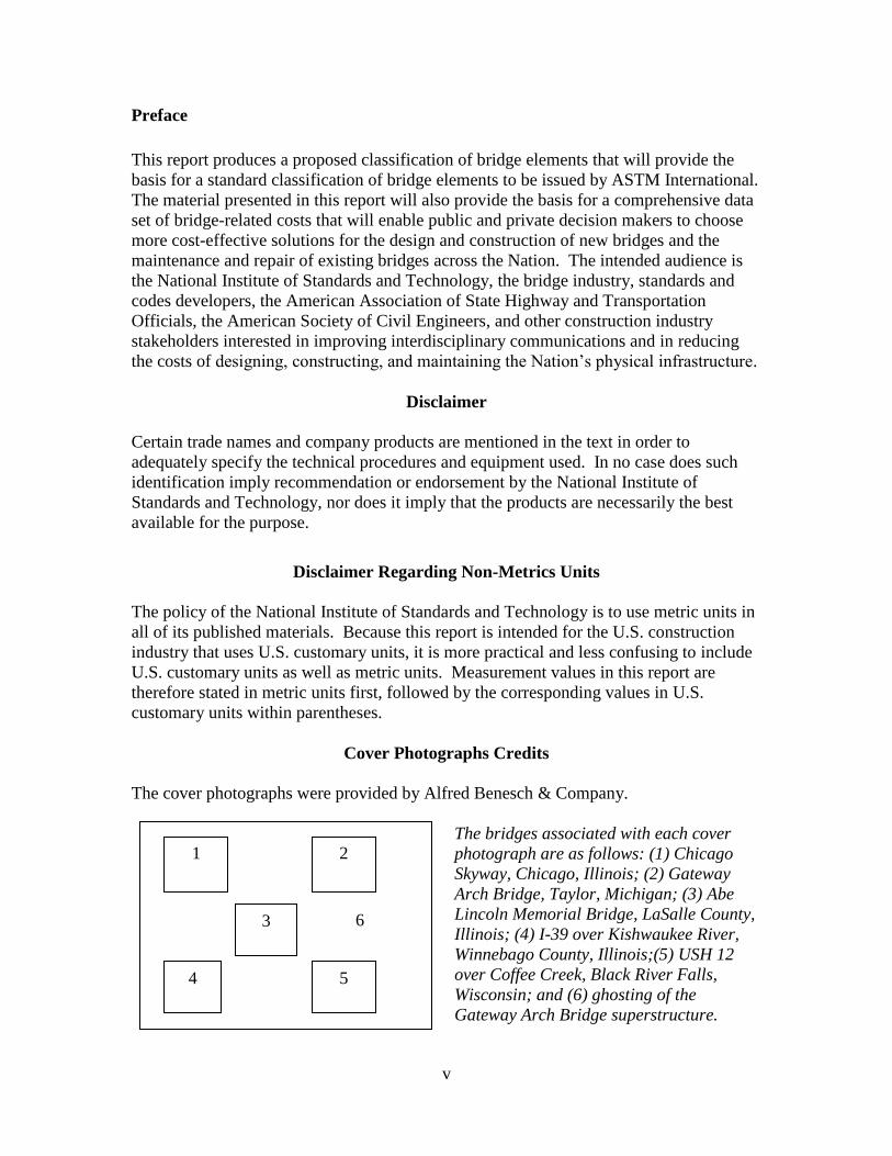
The cover photographs were provided by Alfred Benesch & Company.
The bridges associated with each cover
photograph are as follows: (1) Chicago
Skyway, Chicago, Illinois; (2) Gateway
Arch Bridge, Taylor, Michigan; (3) Abe
Lincoln Memorial Bridge, LaSalle County,
Illinois; (4) I-39 over Kishwaukee River,
Winnebago County, Illinois;(5) USH 12
over Coffee Creek, Black River Falls,
Wisconsin; and (6) ghosting of the
Gateway Arch Bridge superstructure.
6
1
5 4
2
3
vi
Author Affiliations
Muthiah Kasi, PE SE CVS, serves as Chairman of the Board at Alfred Benesch &
Company. Mr. Kasi joined Alfred Benesch & Company in 1969. His experience at
Benesch includes design and management of high rise and low rise buildings, long span
river bridges and short span bridges, and urban and rural highways. Mr. Kasi is the
Chairman of the ASTM Subcommittee on Building Economics, where for nearly 20 years
he has been active in developing standards covering the design, construction, and
operation of constructed facilities.
Robert E. Chapman, Ph.D., is the Chief of the Applied Economics Office in the
Engineering Laboratory at the National Institute of Standards and Technology (NIST).
Dr. Chapman joined NIST, formerly the National Bureau of Standards, in 1975. As
Chief of the Applied Economics Office, he leads a group of economists that evaluate new
technologies, processes, government programs, legislation, and codes and standards to
determine efficient alternatives and measure their economic impacts. Since 1998, Dr.
Chapman has chaired the Task Group on Techniques within the ASTM Subcommittee on
Building Economics.

vii
Acknowledgements
The authors wish to thank all those who contributed so many excellent ideas and
suggestions for this report. They include: Dr. S. Shyam Sunder, Director of the
Engineering Laboratory (EL) at the National Institute of Standards and Technology
(NIST); Dr. William Grosshandler, EL Deputy Director for Building and Fire Research;
Mr. Mark E. Palmer, EL’s Automated and Integrated Infrastructure Construction
Processes Program Manager, for their technical guidance, suggestions, and support.
Special appreciation is extended to Dr. Ihab Darwish, Dr. Michael N. Goodkind, Mr.
Andrew Keaschall, Mr. Robert Tipton, and Ms. Jayne Hill of Alfred Benesch &
Company, for their technical contributions during the drafting and production of this
manuscript. Special appreciation is extended to Dr. Christopher U. Brown of the EL’s
Building Environment Division and Dr. David T. Butry and Dr. Harold E. Marshall of the
EL’s Applied Economics Office for their thorough reviews and many insights. Special
appreciation is extended to Ms. Jayne Hill of Alfred Benesch & Company for her cover
design and graphics skills and to Ms. Carmen L. Pardo of the EL’s Applied Economics
Office for her assistance in preparing the manuscript for review and publication. Special
appreciation is also extended to Ms. Barbara Balboni, Senior Engineer RS Means; Mr.
Robert P. Charette, Adjunct Professor Concordia University; Mr. Anthony L. Huxley,
Construction Consultant; and Mr. Stephen Mawn, Manager Committee E06 on
Performance of Buildings ASTM International, for their comments on an earlier draft of
this report. The report has also benefitted from the review and technical comments
provided by Dr. Nicos S. Martys of the EL’s Materials and Construction Research
Division. We also acknowledge and express our gratitude to the Illinois Department of
Transportation (IDOT) for granting permission to reproduce diagrams from the IDOT
Bridge Standards document in Appendix B: An Illustrated Guide to the Proposed
UNIFORMAT II Classification of Bridge Elements. The diagrams from the IDOT
Bridge Standards document reproduced in this report were in effect on March 25, 2011.
We also acknowledge and express our gratitude to the Michigan Department of
Transportation for granting permission to use the Gateway Arch Bridge as a case
illustration of the proposed UNIFORMAT II classification. The case illustration is
presented in Appendix C.

viii
ix
Table of Contents
Abstract .............................................................................................................................. iii Preface................................................................................................................................. v
Acknowledgements ........................................................................................................... vii
1 Introduction................................................................................................................ 1 1.1 Background ......................................................................................................... 1 1.2 Purpose ................................................................................................................ 3 1.3 Scope and Approach ........................................................................................... 3
2 Proposed UNIFORMAT II Classification of Bridge Elements ............................. 5 2.1 Rationale for Classification................................................................................. 5
2.2 How the Proposed Classification will be Used ................................................... 6
2.3 Basis of Classification......................................................................................... 9 2.4 Description of Proposed UNIFORMAT II Bridge Elements ........................... 12
3 Summary and Recommendations for Further Research ..................................... 31 3.1 Summary ........................................................................................................... 31
3.2 Recommendations for Further Research ........................................................... 31
References ........................................................................................................................ 33
Appendix A Suggested Sub-Classifications of Bridge Elements ............................... 37
Appendix B An Illustrated Guide to the Proposed UNIFORMAT II Classification
of Bridge Elements ................................................................................................... 51
Appendix C Application of Proposed UNIFORMAT II Classification and Sub-
Classifications to a Single-Span, Modified Tied-Arch Bridge ............................. 79
C.1 Summary of Key Bridge Characteristics .......................................................... 79 C.2 Cost Accounting Framework ............................................................................ 85 C.3 Cost Analysis of the Gateway Arch Bridge Using the Proposed UNIFORMAT
II Elemental Classification and Sub-Classifications ..................................................... 87
List of Figures
Figure B.1 Major Group Elements: A Substructure, B Superstructure ........................... 51
Figure B.2 Group Elements: A10 Piers ........................................................................... 52 Figure B.3 Group Elements: A10 Piers ........................................................................... 52 Figure B.4 Individual Elements: A1010 Foundations (Field Requirements: A101010X1
(Cofferdam)) ............................................................................................................. 53 Figure B.5 Individual Elements: A1010 Foundations (Sub-Elements: A101010 Spread
Footings (Excavation)).............................................................................................. 53 Figure B.6 Individual Elements: A1010 Foundations (Sub-Elements: A101020 Piles) . 54
Figure B.7 Individual Elements: A1010 Foundations (Sub-Elements: A101030 Drilled
Shafts) ....................................................................................................................... 54 Figure B.8 Individual Elements: A1020 Walls, A1030 Columns, A1040 Cap Beams ... 55
x
Figure B.9 Individual Elements: A1040 Cap Beams (Sub-Elements: A10401020
Reinforcement) ......................................................................................................... 55 Figure B.10 Individual Elements: A1040 Cap Beams ..................................................... 56 Figure B.11 Group Elements: A20 Towers ..................................................................... 56
Figure B.12 Group Elements: A30 Abutments ................................................................ 57 Figure B.13 Individual Elements: A3010 Foundations, A3020 Stems, A3030 Wing Walls
................................................................................................................................... 57 Figure B.14 Individual Elements: A3010 Foundations (Sub-Elements: A301020 Piles,
A30102030 Pile Cap) ................................................................................................ 58
Figure B.15 Individual Elements: A3020 Stems ............................................................. 58 Figure B.16 Individual Elements: A3030 Wing Walls .................................................... 59 Figure B.17 Group Elements: A40 Other Supports (Individual Elements: A4010 Thrust
Blocks) ...................................................................................................................... 59
Figure B.18 Individual Elements: A4010 Thrust Blocks (Sub-Elements: A401020
Foundations (A40102020 Piles)) .............................................................................. 60
Figure B.19 Group Elements: B10 Short Span Assemblies (Individual Elements: B1010
Flexural Member, B1020 Diaphragms), B30 Deck .................................................. 60
Figure B.20 Individual Elements: B1010 Flexural Members, B1020 Diaphragms ......... 61 Figure B.21 Individual Elements: B1020 Diaphragms .................................................... 61 Figure B.22 Individual Elements: B1030 Bracings ......................................................... 62
Figure B.23 Individual Elements: B1030 Bracings ......................................................... 62 Figure B.24 Individual Elements: B1040 Bearings ......................................................... 63
Figure B.25 Individual Elements: B1010 Flexural Members, B1030 Bracings, B1040
Bearings .................................................................................................................... 63 Figure B.26 Group Elements: B20 Long Span Assemblies (Individual Elements: B2010
Ribs, B2030 Hangers) ............................................................................................... 64
Figure B.27 Individual Elements: B2030 Hangers .......................................................... 64 Figure B.28 Individual Elements: B2010 Ribs, B2050 Ties ........................................... 65 Figure B.29 Individual Elements: B2040 Spandrels........................................................ 65
Figure B.30 Individual Elements: B2060 Truss Members .............................................. 66 Figure B.31 Individual Elements: B2070 Segmental Box Girders .................................. 66
Figure B.32 Group Elements: B30 Deck (Individual Elements: B3010 Structural
Surface) ..................................................................................................................... 67
Figure B.33 Individual Elements: B3020 Wearing Surface ............................................ 67 Figure B.34 Group Elements: C10 Structure Protection (Individual Elements:C1010
Slope Walls) .............................................................................................................. 68 Figure B.35 Individual Elements: C1020 Expansion Joints ............................................ 68 Figure B.36 Individual Elements: C1030 Protection Coats ............................................. 69
Figure B.37 Individual Elements: C1040 Sacrificial Beams ........................................... 69 Figure B.38 Individual Elements: C1050 Drainage Systems .......................................... 70
Figure B.39 Individual Elements: C1050 Drainage Systems (Sub-Elements C105030
Buried Drains (C10503020 Head Walls, C10503030 End Walls)) .......................... 70 Figure B.40 Individual Elements: C1060 Inspection and Maintenance Systems ............ 71 Figure B.41 Individual Elements: C2010 Barriers .......................................................... 71 Figure B.42 Group Elements: C30 Other Protection (Individual Elements: C3010
Lighting) ................................................................................................................... 72

xi
Figure B.43 Individual Elements: C3010 Lighting, C3020 Signage ............................... 72
Figure B.44 Individual Elements: C3020 Signage .......................................................... 73 Figure B.45 Individual Elements: C3030 Sound Barrier Walls ...................................... 73 Figure B.46 Individual Elements: C3050 Enclosure ....................................................... 74
Figure B.47 Major Elements: D Sitework (Group Elements: D10 Site Preparation
(Individual Elements: D1010 Clearing and Grubbing)) ........................................... 74 Figure B.48 Individual Elements: D1010 Clearing and Grubbing (Sub-Element D101010
Clearing (Tree Removal)) ......................................................................................... 75 Figure B.49 Group Elements: D10 Site Preparation (Individual Elements: D1020
Demolition and Relocation) ...................................................................................... 75 Figure B.50 Individual Elements: D1020 Demolition and Relocation ............................ 76 Figure B.51 Individual Elements: D1030 Earthwork ...................................................... 76 Figure B.52 Group Elements: D20 Approach Construction (Individual Elements: D2010
Approach Slabs, D2020 Sleeper Slabs) .................................................................... 77 Figure B.53 Individual Elements: D2030 Earth Retention System ................................. 77
Figure C.154Overhead View of the Gateway Arch Bridge .............................................. 79 Figure C.255Gateway Arch Bridge as Seen from Telegraph Road .................................. 80
Figure C.356Gateway Arch Bridge as Seen from I-94 ..................................................... 80 Figure C.457Gateway Arch Bridge Foundation System .................................................. 81 Figure C.558Longitudinal View of the Arch Ribs............................................................ 82
Figure C.659Transverse View of the Arch Ribs Illustrates Unequal Lengths ................. 83 Figure C.760Access Opening to the Arch Rib.................................................................. 84
Figure C.861Hanger Assembly and Neoprene Transition Boots...................................... 84 Figure C.962Cost Distribution of Selected Group Elements and Individual Elements for
the Gateway Arch Bridge .......................................................................................... 89
List of Tables
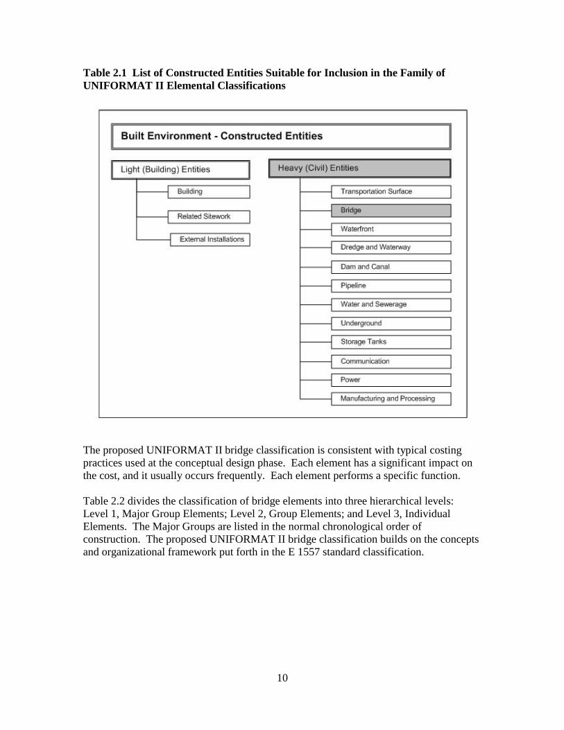
Table 2.1 List of Constructed Entities Suitable for Inclusion in the Family of
UNIFORMAT II Elemental Classifications ............................................................. 10
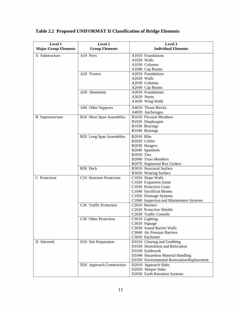
Table 2.2 Proposed UNIFORMAT II Classification of Bridge Elements ....................... 11 Table 2.3 Description of Proposed UNIFORMAT II Bridge Elements .......................... 14 Table A.1 Suggested Sub-Classifications of Bridge Elements ........................................ 38 Table C.1 Classification Hierarchy for Program Management-Related Costs ................ 86 Table C.2 Classification Hierarchy for Risk Management-Related Costs ...................... 86
Table C.3 Cost Analysis of the Gateway Arch Bridge Using the Proposed UNIFORMAT
II Elemental Classification and Sub-Classifications ................................................. 88

xii
1
1 Introduction
1.1 Background
The use of elemental classifications for improved budget planning and cost control for
building-related projects began shortly after the end of World War II. Elemental
classifications differ from the traditional “product-related” classifications because their
core concept is an “element” that performs a given function, regardless of the design
specification, construction method, or materials used. Thus, elemental classifications
support a structured approach for developing budget estimates during the planning and
conceptual design stages where quantity takeoffs and other product-related information
are still under development.
The initial applications of elemental classifications were in the UK, where they were used
for budgeting funds to repair educational facilities damaged or destroyed during World
War II and to build new facilities to meet increased demands due to population growth.
The UK successes with budgeting and cost control for educational facilities led to
applications in other building types within the UK and ultimately in other parts of
Europe. By the 1960s, the use of elemental classifications for budgeting and estimating
the costs of the design and construction of commercial and institutional buildings had
spread throughout the British Commonwealth and many other parts of the world.1
The use of elemental classifications for commercial and institutional buildings in the
USA began in the 1950s. These initial applications were led by the General Services
Administration (GSA) and the American Institute of Architects (AIA). The interest in
producing a common framework that could be used by all stakeholders in the design,
construction, and operation of commercial and institutional buildings led to the creation
of UNIFORMAT in 1975.2
The initial success of UNIFORMAT stimulated interest in expanding its capabilities to
other types of constructed entities. In the late 1980s, a broad-based effort under the
auspices of the Building Economics Subcommittee of ASTM International was launched
to produce a standard classification of building elements and related sitework.3 The
resulting standard, E 1557, was first issued by ASTM in 1993. Over the ensuing years,
E 1557—refered to as UNIFORMAT II to highlight its linkage to the earlier
UNIFORMAT document—has been revised and expanded to meet new and emerging
needs.4
1 Royal Institute of Chartered Surveyors (RICS). 1969. Standard Form of Cost Analysis. London, England:
The Building Cost Information Service. 2 Hanscomb Associates, Inc. 1975. Automated Cost Control and Estimating System. Washington, DC:
General Services Administration. 3 Brian Bowen, Robert P. Charette, and Harold E. Marshall. 1992. UNIFORMAT II: A Recommended
Classification for Building Elements and Related Sitework, NIST Special Publication 841. Gaithersburg,
MD: National Institute of Standards and Technology. 4 ASTM International. “Classification of Building Elements and Related Sitework—UNIFORMAT II,”
E 1557, Annual Book of ASTM Standards: 2010, Vol. 4.11. West Conshohocken, PA: ASTM International.

2
The latest version of E 1557 focuses primarily on buildings but has broad applicability to
other types of constructed entities. Current applications of E 1557 include: planning
estimates; program estimates; preliminary project descriptions; preliminary construction
schedules and cash flow projections; design phase estimates; CAD layering and building
information modeling (BIM); life-cycle cost analysis reporting; checklists for technical
design reviews; project scheduling; construction progress reporting and interim
payments; construction claims analysis; building condition assessment; organizing
design, engineering, and construction cost information for manuals and databases; and
organizing maintenance and life-cycle cost data.5
The widespread use of E 1557—it is one of the top selling standards from ASTM’s
inventory of over 12 000 standards—sparked interest in standard classifications for other
types of constructed entities. Several ASTM standard classifications were subsequently
developed, most notably a bridge-related classification, E 2103.6 However, standard
classification E 2103 differed from the underlying “elemental” concept that was at the
heart of E 1557. To address the need for a more rigorous “family” of classification
standards based on the UNIFORMAT II elemental concept, the Building Economics
Subcommittee, ASTM E06.81, formed a task group charged with the development of a
set of “Guidelines for Developing UNIFORMAT II Standard Classifications.”7 The
UNIFORMAT II Guidelines were first approved by the Building Economics
Subcommittee in April 2009 and were posted on the ASTM E06.81 web site in May
2009.8
Because bridges are a critical component of the Nation’s infrastructure and many bridges
are in need of significant capital outlays over the coming years to both remedy safety
concerns and build new capacity for multiple modes of transportation,9 a major revision
to the existing bridge classification, E 2103, is both timely and appropriate. At the
October 2009 ASTM E06.81 meeting, a motion was passed to completely revise and
restructure E 2103 to be fully consistent with the UNIFORMAT II Guidelines document.
Plans for revising and restructuring E 2103 were presented at the April 2010 and October
2010 ASTM E06.81 meetings. This report expands on those plans by providing an in-
depth description of what the restructured version of E 2103 will include to bring it into
full compliance with the UNIFORMAT II Guidelines document. Two major extensions
to the proposed UNIFORMAT II classification of bridge elements are also presented.
Once approved and reissued by ASTM, the UNIFORMAT II Standard Classification of
Bridge Elements, E 2103, will provide the basis for a comprehensive data set of bridge-
5 Robert P. Charette and Harold E. Marshall. 1999. UNIFORMAT II: Elemental Classification for Building
Specifications, Cost Estimating, and Cost Analysis, NISTIR 6389. Gaithersburg, MD: National Institute of
Standards and Technology. 6 ASTM International. “Classification of Bridge Elements and Related Approach Work,” E 2103, Annual
Book of ASTM Standards: 2010, Vol. 4.12. West Conshohocken, PA: ASTM International. 7 ASTM International. “Guidelines for Developing UNIFORMAT II Standard Classifications,” Working
Paper. West Conshohocken, PA: ASTM International. 8 http://www.astm.org/COMMIT/SUBCOMMIT/E0681.htm (accessed December 2010).
9 ASCE 2009 Report Card for America’s Infrastructure. http://www.infrastructurereportcard.org/ (accessed
December 2010).

3
related costs that will enable public and private decision makers to choose more cost-
effective solutions for the design and construction of new bridges and the maintenance
and repair of existing bridges across the Nation.
1.2 Purpose
The purpose of this report is threefold. First and foremost, it presents a proposed
UNIFORMAT II classification of bridge elements. The proposed classification
represents a major revision and restructuring of ASTM Standard Classification E 2103
first issued in 2000 and reissued in 2006. The original bridge classification, E 2103,
differed from the UNIFORMAT II elemental classification hierarchy in several ways
which limited its applicability. The proposed major revision and restructuring presented
in this report is fully consistent with the UNIFORMAT II Guidelines document
established by the ASTM E06.81 Subcommittee on Building Economics. These major
revisions to E 2103 will promote its relevance, understanding, and acceptance in the
bridge industry.
Second, this report includes a set of alphanumeric designators for the proposed multi-
level bridge classification. Because many users are interested in constructing databases
for use in cost analyses associated with project planning, design, construction,
maintenance and repair, and condition assessment, alphanumeric designators provide the
basis for compiling, organizing, and referencing cost data. Having a common set of
alphanumeric designators promotes consistency in use among the key project participants
and other stakeholders associated with the design, construction, and use of bridges and
other constructed entities.
Third, this report includes a proposed list of sub-elements for bridges. As noted earlier,
the primary focus of the UNIFORMAT II Standard Classification E 1557 and its
associated family is on the elemental concept. The UNIFORMAT II hierarchy consists
of three levels: Level 1, Major Group Elements; Level 2, Group Elements; and Level 3,
Individual Elements. Thus, the core concept of an element resides at Level 3. All three
levels are treated in detail in the body of this report and are intended to serve as the basis
for the proposed revisions to E 2103. However, because elements—Level 3 in a
UNIFORMAT II hierarchy—are major components of a constructed entity (e.g., a
bridge), there is often ambiguity of what exactly is included in an Individual Element and
what should be rightfully excluded from it. By providing a proposed set of sub-elements
as an appendix, this report lays the framework for evaluating the merits of including such
a list in E 2103 along with the other proposed revisions discussed in the body of the text.
Because sub-elements can be tied into a work breakdown structure, they significantly
enhance the usefulness of an elemental classification across all project participants
throughout the lifecycle of bridges and other constructed entities.
1.3 Scope and Approach
The report consists of two chapters and three appendices in addition to the Introduction.
Chapter 2 presents the proposed UNIFORMAT II classification of bridge elements. The

4
chapter first discusses the rationale for undertaking a major revision of the original
E 2103 bridge classification to make it consistent with the UNIFORMAT II Guidelines
document established by the ASTM E06.81 Subcommittee on Building Economics. The
potential uses of the proposed bridge classification are then discussed. The proposed
bridge classification is then described and summarized as a hierarchy with three levels:
Level 1, Major Group Elements; Level 2, Group Elements; and Level 3, Individual
Elements. The chapter concludes with an element-by-element description of the
proposed bridge classification.
Chapter 3 provides a summary and recommendations for further research. Specifically,
four additional UNIFORMAT II classifications are proposed for development: (1)
tunnels; (2) highways; (3) railroads; and (4) water treatment and distribution. Each of
these classifications corresponds to a critical infrastructure need identified in the
American Society of Civil Engineers Report Card for America’s Infrastructure.10
Appendix A presents suggested sub-classifications of bridge elements. The sub-
classifications expand the Level 3 Individual Elements into their constituent parts. These
constituent parts include a Level 4 for all Individual Elements and, where necessary, a
Level 5 (i.e., subdivisions of Level 4).
Appendix B is designed as an illustrated guide to the proposed UNIFORMAT II
classification of bridge elements. The appendix includes diagrams, engineering
drawings, and, where appropriate, photographs to identify the appearance of each element
and how it fits into the overall framework.
Appendix C uses a case study bridge construction project to demonstrate how to use the
proposed UNIFORMAT II classification and sub-classifications to analyze and manage
bridge design and construction costs. The bridge is a single-span, modified tied-arch
carrying Interstate 94 (I-94) over Telegraph Road in Taylor, Michigan. This bridge was
part of the reconstruction of I-94 for the Super Bowl XL game held in 2006.
10
ASCE 2009 Report Card for America’s Infrastructure, op cit.
5
2 Proposed UNIFORMAT II Classification of Bridge Elements
2.1 Rationale for Classification
The Engineering Laboratory at NIST has launched the Automated and Integrated
Infrastructure Construction Processes Program to investigate the challenges and evolving
technologies needed to enable the construction industry to develop best practices,
protocols, and standards to achieve breakthrough improvements in construction
productivity and the delivery of physical infrastructure. The timely and cost effective
delivery of physical infrastructure is a critical national need. The ASCE Report Card for
America’s Infrastructure highlights the need for maintaining a robust infrastructure to
promote the Nation’s current standard of living and to advance its competitiveness.
Unfortunately, much of the Nation’s physical infrastructure is nearing the end of its
service life and needs to be repaired or replaced. ASCE estimates the cost of renewing
existing, critical infrastructure to be $2.2 trillion.11
Bridges are an important part of the Nation’s physical infrastructure. Although bridges
are usually built to last 50 years, AASHTO estimates that the average bridge in the USA
is 43 years old.12
More than 26 %, or one in four, of the Nation’s 609 905 bridges are
either structurally deficient or functionally obsolete. A $17 billion annual investment is
needed to substantially improve current bridge conditions. Currently, only $10.5 billion
is spent annually on the construction and maintenance of bridges.13
In response to this challenge, this report presents a proposed classification of bridge
elements within the UNIFORMAT II family of elemental classifications that covers most
highway bridges, railroad bridges, and pedestrian bridges. The proposed classification
represents a major revision and restructuring of ASTM Standard Classification E 2103,14
a bridge-related standard classification first issued by ASTM in 2000. The original
bridge classification, E 2103, differed from the UNIFORMAT II elemental classification
hierarchy15
in several ways which limited its applicability. The major revisions to E 2103
described in this chapter will promote its relevance, understanding, and acceptance in the
bridge industry. Once approved and reissued by ASTM, the UNIFORMAT II Standard
Classification of Bridge Elements, E 2103, will provide the basis for a comprehensive
data set of bridge-related costs that will enable public and private decision makers to
choose more cost-effective solutions for the design and construction of new bridges and
the maintenance and repair of existing bridges across the Nation.
11
ASCE 2009 Report Card for America’s Infrastructure, op cit. 12
American Association of State Highway and Transportation Officials (AASHTO). 2008. Bridging the
Gap. Washington, DC: AASHTO. 13
American Society of Civil Engineers. 2009. Facts About Bridges. 14
ASTM International. E 2103, “Classification of Bridge Elements and Related Approach Work,” op cit. 15
ASTM International. E 1557, “Classification of Building Elements and Related Sitework—
UNIFORMAT II,” op cit.
6
UNIFORMAT II classifications have an elemental format similar to the original
UNIFORMAT16
building elemental classification. However, the title UNIFORMAT II
differs from the original in that it now takes into consideration a wide range of
constructed entities that collectively form the “Built Environment.” Elements, as defined
here, are major physical components that are common within constructed entities.
Elements perform their given function(s), regardless of the design specification,
construction method, or materials used. This proposed elemental classification serves as
a consistent reference for analysis, evaluation, and monitoring during the feasibility,
planning, and design stages when constructing bridges.
Using the UNIFORMAT II Guidelines document17
to develop elemental classifications
ensures a consistency in the economic evaluation of construction projects over time and
from project to project. UNIFORMAT II classifications also enhance reporting at all
stages of a constructed entity’s life cycle—from feasibility and planning through the
preparation of working documents, construction, maintenance, rehabilitation, and
disposal.
2.2 How the Proposed Classification will be Used
The proposed UNIFORMAT II classification presented in this report describes bridge
elements that are major components of most highway, railroad, and pedestrian bridges.
This section covers both the potential users of the proposed UNIFORMAT II
classification of bridge elements and the various ways in which the proposed
classification can be used to promote more cost-effective bridges throughout their
lifecycle.18
The elemental classification is the common thread linking activities and
participants in a bridge project from initial planning through operations, maintenance,
and disposal.
As the proposed UNIFORMAT II classification of bridge elements refers solely to
permanent, physical parts of any bridge construction, two ASTM Standard
Classifications, E 208319
and E 2168,20
need to be included when calculating
construction cost. These standards provide for the inclusion of construction enabling,
temporary, and risk mitigation cost figures. Procedures for reporting all these figures are
16 The original UNIFORMAT classification was developed jointly by the General Services Administration
(GSA) and the American Institute of Architects (AIA). 17
ASTM International. “Guidelines for Developing UNIFORMAT II Standard Classifications,” op cit. 18
For additional information on the uses of ASTM Standard Classification E 1557, see Bowen, Charette,
and Marshall, UNIFORMAT II—A Recommended Classification for Building Elements and Related
Sitework, NIST Special Publication 841, op cit, and Charette and Marshall, UNIFORMAT II Elemental
Classification for Building Specifications, Cost Estimating, and Cost Analysis, NISTIR 6389, op cit. 19
ASTM International. “Classification for Building Construction Field Requirements, and Office Overhead
and Profit,” E 2083, Annual Book of ASTM Standards: 2010, Vol. 4.11. West Conshohocken, PA: ASTM
International. 20
ASTM International. “Classification for Allowance, Contingency and Reserve Sums in Building
Construction Estimating,” E 2168, Annual Book of ASTM Standards: 2010, Vol. 4.12. West Conshohocken,
PA: ASTM International.
7
described in ASTM standards E 1804,21
E 2514,22
and E 2516.23
While these three latter
standards were primarily written for building construction, they are nonetheless
appropriate and readily applied to other forms of construction as well.
Users of the Proposed UNIFORMAT II Classification of Bridge Elements
Financial and Investment—Typically owners, developers, bankers, lenders, accountants,
and financial managers.
Implementation—Primarily project managers; facilities programmers; designers,
including engineers; and project controls specialists, including cost planners, estimators,
schedulers, specification writers, and risk analysts.
Facilities Management—Comprising property portfolio managers, operating staff, and
maintenance staff.
Others—Public officials, manufacturers, educators, students, and other project
stakeholders.
Applications of the Proposed UNIFORMAT II Classification of Bridge Elements
Financing and Investing—Structuring costs on an elemental basis for economic
evaluations (ASTM Standard Practices E 917,24
E 964,25
E 1057,26
E 1074,27
E 1121,28
and E 180429
) early in the design process helps reduce the cost of early financial analysis
21
ASTM International. “Practice for Performing and Reporting Cost Analysis During the Design Phase of a
Project,” E 1804, Annual Book of ASTM Standards: 2010, Vol. 4.11. West Conshohocken, PA: ASTM
International. 22
ASTM International. “Practice for Presentation Format of Elemental Cost Estimates, Summaries, and
Analyses,” E 2514, Annual Book of ASTM Standards: 2010, Vol. 4.12. West Conshohocken, PA: ASTM
International. 23
ASTM International. “Classification for Cost Estimate Classification System,” E 2516, Annual Book of
ASTM Standards: 2010, Vol. 4.12. West Conshohocken, PA: ASTM International. 24
ASTM International. “Practice for Measuring Life-Cycle Costs of Buildings and Building Systems,”
E 917, Annual Book of ASTM Standards: 2010, Vol. 4.11. West Conshohocken, PA: ASTM International. 25
ASTM International. “Practice for Measuring Benefit-to-Cost and Savings-to-Investment Ratios for
Buildings and Building Systems,” E 964, Annual Book of ASTM Standards: 2010, Vol. 4.11. West
Conshohocken, PA: ASTM International. 26
ASTM International. “Practice for Measuring Internal Rate of Return and Adjusted Internal Rate of
Return for Investments in Buildings and Building Systems,” E 1057, Annual Book of ASTM Standards:
2010, Vol. 4.11. West Conshohocken, PA: ASTM International. 27
ASTM International. “Practice for Measuring Net Benefits and Net Savings for Investments in Buildings
and Building Systems,” E 1074, Annual Book of ASTM Standards: 2010, Vol. 4.11. West Conshohocken,
PA: ASTM International. 28
ASTM International. “Practice for Measuring Payback for Investments in Buildings and Building
Systems,” E 1121, Annual Book of ASTM Standards: 2010, Vol. 4.11. West Conshohocken, PA: ASTM
International. 29
ASTM International. “Practice for Performing and Reporting Cost Analysis During the Design Phase of a
Project,” E 1804, op cit.
8
and can contribute to substantial design and operational savings before decisions have
been made that limit options for potential savings.
Cost Modeling, Cost Planning, Estimating and Controlling Project Time and Cost
During Planning, Design, and Construction—Use the bridge UNIFORMAT II
classification to prepare budgets and to establish elemental cost plans before design
begins. Project managers and project controls specialists use these cost plans against
which to measure and control project cost, and quality, and to set design-to-cost targets.
Conducting Value Engineering Workshops—Conducting value engineering workshops
(ASTM Standard Practices E 169930
and E 201331
). Use this classification as a checklist
to ensure that alternatives for all elements of significant cost in the bridge project are
analyzed in the creativity phase of the job plan. Also, use the elemental cost data to
expedite the development of cost models for bridge systems.
Developing Initial Project Master Schedules—Since projects are essentially built element
by element, UNIFORMAT II classifications are an appropriate basis for preparing
construction schedules at the start of the design process. Project managers and project
controls specialists use these time plans against which to measure and control project
time (ASTM Standard Practice E 269132
), prepare detailed project schedules, and to set
milestone target dates.
Performing Risk Analyses—Simulation (ASTM Standard Guides E 136933
and E 250634
)
is one technique for developing probability distributions of bridge costs when evaluating
the economic risk in undertaking a bridge project. Use individual elements and group
elements in this classification for developing probability distributions of elemental costs.
From these distributions, build up probability distributions of total costs to establish
project contingencies (ASTM Standard Practice E 194635
and ASTM Standard
Classification E 216836
) or to serve as inputs to an economic analysis.
30
ASTM International. “Practice for Performing Value Analysis (VA) of Buildings and Building Systems,”
E 1699, Annual Book of ASTM Standards: 2010, Vol. 4.11. West Conshohocken, PA: ASTM International. 31
ASTM International. “Practice for Constructing FAST Diagrams and Performing Function Analysis
During Value Analysis Study,” E 2013, Annual Book of ASTM Standards: 2010, Vol. 4.11. West
Conshohocken, PA: ASTM International. 32
ASTM International. “Practice for Job Productivity Measurement,” E 2691, Annual Book of ASTM
Standards: 2010, Vol. 4.12. West Conshohocken, PA: ASTM International. 33
ASTM International. “Guide for Selecting Techniques for Treating Uncertainty and Risk in the
Economic Evaluation of Buildings and Building Systems,” E 1369, Annual Book of ASTM Standards:
2010, Vol. 4.11. West Conshohocken, PA: ASTM International. 34
ASTM International. “Guide for Developing a Cost-Effective Risk Mitigation Plan for New and Existing
Constructed Facilities,” E 2506, Annual Book of ASTM Standards: 2010, Vol. 4.12. West Conshohocken,
PA: ASTM International. 35
ASTM International. “Practice for Measuring Cost Risk of Buildings and Building Systems,” E 1946,
Annual Book of ASTM Standards: 2010, Vol. 4.11. West Conshohocken, PA: ASTM International. 36
ASTM International. “Classification for Allowance, Contingency and Reserve Sums in Building
Construction Estimating,” E 2168, op cit.

9
Structuring Preliminary Project Descriptions During the Conceptual Design Phase—
This classification facilitates the description of the scope of the project in a clear, concise,
and logical sequence for presentation to the client; it provides the basis for the
preparation of more detailed elemental estimates during the early concept and
preliminary design phases, and it enhances communication between designers and clients
by providing a clear statement of the designer’s intent.
Coding and Referencing Standard Details In Computer-Aided Design Systems—This
classification allows a designer, for example, to reference an assembly according to this
classification’s element designations and build up a database of standard details. This is
particularly appropriate to design modeling and building information modeling (BIM)
applications.
Managing Facilities—Recording and writing property condition assessment reports in a
structured way, using UNIFORMAT II classifications, provides for a consistent,
accessible, and searchable database of real property inventory.
Other Activities—Structuring cost manuals and recording construction, operating, and
maintenance costs in a computer database. Having a cost manual or computer database
in an elemental format assists the preparation of an economic analysis early in the design
stage and at a reasonable cost.
2.3 Basis of Classification
The framework in Table 2.1 shows the two branches that serve to define the built
environment—light construction associated with buildings and heavy construction
associated with civil structures. Under each branch are listed, the various constructed
entities that collectively are used to create the built environment. Each entity is treated as
a module, where a module may result in one or more UNIFORMAT II elemental
classifications. Appropriate modules, and the standards associated with them, when used
together will effectively describe any planned or built development.
The proposed classification covered in this report describes exclusively the elements that
make up one of those constructed entities, bridge structures, shown as the shaded block
under the heading of Heavy (Civil) Entities. This bridge classification is applicable to
most types of highway, railroad, and pedestrian bridges.
The classification includes: slab bridges; beam/girder bridges; truss bridges; true
and tied-arch bridges; cable-stayed bridges; and suspension bridges.
The classification does not include the following movable bridge types: draw
bridges; lift bridges; and bascule bridges.
10
Table 2.1 List of Constructed Entities Suitable for Inclusion in the Family of
UNIFORMAT II Elemental Classifications
The proposed UNIFORMAT II bridge classification is consistent with typical costing
practices used at the conceptual design phase. Each element has a significant impact on
the cost, and it usually occurs frequently. Each element performs a specific function.
Table 2.2 divides the classification of bridge elements into three hierarchical levels:
Level 1, Major Group Elements; Level 2, Group Elements; and Level 3, Individual
Elements. The Major Groups are listed in the normal chronological order of
construction. The proposed UNIFORMAT II bridge classification builds on the concepts
and organizational framework put forth in the E 1557 standard classification.
11
Table 2.2 Proposed UNIFORMAT II Classification of Bridge Elements
Level 1
Major Group Elements
Level 2
Group Elements
Level 3
Individual Elements
A Substructure A10 Piers A1010 Foundations
A1020 Walls
A1030 Columns
A1040 Cap Beams
A20 Towers A2010 Foundations
A2020 Walls
A2030 Columns
A2040 Cap Beams
A30 Abutments A3010 Foundations
A3020 Stems
A3030 Wing Walls
A40 Other Supports A4010 Thrust Blocks
A4020 Anchorages
B Superstructure B10 Short Span Assemblies B1010 Flexural Members
B1020 Diaphragms
B1030 Bracings
B1040 Bearings
B20 Long Span Assemblies B2010 Ribs
B2020 Cables
B2030 Hangers
B2040 Spandrels
B2050 Ties
B2060 Truss Members
B2070 Segmental Box Girders
B30 Deck B3010 Structural Surface
B3020 Wearing Surface
C Protection C10 Structure Protection C1010 Slope Walls
C1020 Expansion Joints
C1030 Protective Coats
C1040 Sacrificial Beams
C1050 Drainage Systems
C1060 Inspection and Maintenance Systems
C20 Traffic Protection C2010 Barriers
C2020 Protective Shields
C2030 Traffic Controls
C30 Other Protection C3010 Lighting
C3020 Signage
C3030 Sound Barrier Walls
C3040 Air Pressure Barriers
C3050 Enclosure
D Sitework D10 Site Preparation D1010 Clearing and Grubbing
D1020 Demolition and Relocation
D1030 Earthwork
D1040 Hazardous Material Handling
D1050 Environmental Restoration/Replacement
D20 Approach Construction D2010 Approach Slabs
D2020 Sleeper Slabs
D2030 Earth Retention Systems

12
Sub-Classifications (see Appendix A) are named Sub-Elements and comprise as many
hierarchical levels (Level 4 and below) as are deemed appropriate to the needs of that
specific example.
The decision as to where among the classification elements to include specific
construction items will rely on professional judgment as to where professionals in current
practice normally look for such items.
Only items that impact the choice and cost of the bridge elements are included. Other
civil works in the transportation system are not included. Consequently, the proposed
classification does not include utilities—pipelines (water, natural gas, and petroleum)
and transmission lines (electrical, communication, and video)—sharing the same right
of way as the transportation system.
Elements, as used and defined in the UNIFORMAT II family of classifications, will
ideally display the following additional attributes:
Capable of being defined precisely;
Self-explanatory;
Separable at all stages of development;
Quantifiable at all stages of development;
Capable of reconciliation with other elemental classifications;
Allow comparisons, project to project, in a meaningful way;
Is a functional component of the constructed entity.
Sitework elements are provided in the proposed classification for exclusive use in support
of the construction of bridges, not to classify elements of major civil construction works.
Sitework elements presented in Table 2.2 are designed to provide sufficient detail to
planners so they will not need to resort to other elemental classifications when working
on a bridge project.
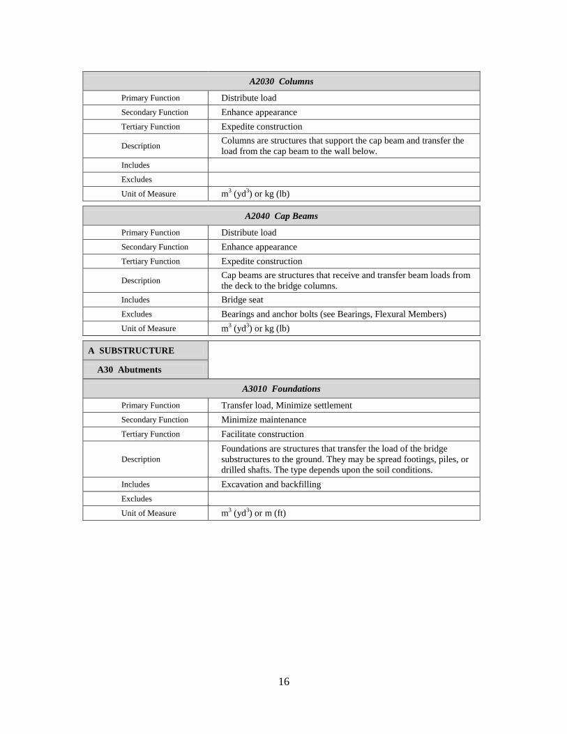
2.4 Description of Proposed UNIFORMAT II Bridge Elements
Table 2.3 provides, for each Level 3 Individual Element, the name, functions, description,
inclusions, exclusions, and unit of measure. The table uses the framework outlined in the
UNIFORMAT II Guidelines document.37
The goal of that framework is to briefly, yet
concisely, summarize the important features of each element. As a complement to the
material presented in this section, this report includes Appendix B and Appendix C to
facilitate the use of the proposed UNIFORMAT II classification of bridge elements.
37
ASTM International. “Guidelines for Developing UNIFORMAT II Standard Classifications,” op cit.

13
Appendix B is designed as an illustrated guide to the proposed UNIFORMAT II
classification of bridge elements. The appendix includes diagrams, engineering
drawings, and, where appropriate, photographs to identify the appearance of each element
and how it fits into the overall framework.
Appendix C uses a case study bridge construction project to demonstrate how to use the
proposed UNIFORMAT II classification and sub-classifications to analyze and manage
bridge design and construction costs. The case study bridge is a single-span, modified
tied-arch carrying Interstate 94 (I-94) over Telegraph Road in Taylor, Michigan. This
bridge was part of the reconstruction of I-94 for the Super Bowl XL game held in 2006.
The functions are classified as Primary, Secondary, and Tertiary. All three levels of
functions may be served. However, one or two functions may be the driving force behind
the existence of the element, and they are classified as Primary functions.
The element descriptions provide an understanding of the purpose and application of the
element. The narrative is intended to provide a brief synopsis of the key features which
serve to define the element.
The purpose of the element inclusions is to list features that make up the element.
The purpose of the element exclusions is to list features that are not included in the
element but which are included elsewhere in the proposed classification. Because this
classification refers solely to permanent physical parts of bridge constructions,
references to construction enabling (cranes and formwork), temporary construction
(cofferdams and traffic detours), and risk mitigation (allowances and contingencies)
cost figures are omitted from the element exclusions.38
The purpose of the unit of measure is to provide a means for calculating the magnitude,
or size, of each element in any bridge description; units of measure are important to all
users of elemental classifications. Units of measure are of prime importance in the
elemental cost management process. Both SI and Customary units are reported. SI units
are reported first followed by Customary units within parentheses. Table 2.3 uses the
following unit of measure abbreviations: linear meters (m) and linear feet (ft); square
meters (m2) and square feet (ft
2); cubic meters (m
3) and cubic yards (yd
3); and kilograms
(kg) and pounds (lb).
38
Appendix C provides for the inclusion of construction enabling, temporary, and risk mitigation cost
figures. Two tables are used to introduce costs related to program management (field requirements and
office overhead and profit) and risk management (allowances, contingencies, and reserve sums). Cost data
for the Telegraph Road bridge are then tabulated and analyzed using the two tables referenced above and
the proposed classification presented in this section and the sub-classifications presented in Appendix A.

14
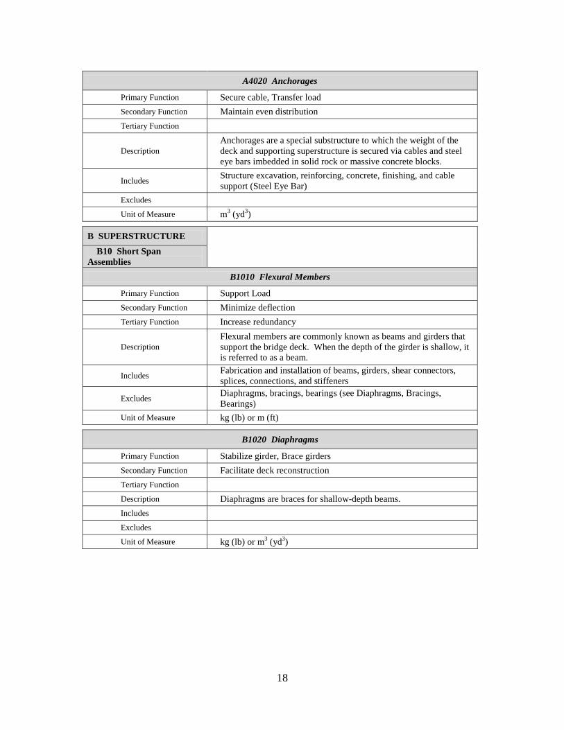
Table 2.3 Description of Proposed UNIFORMAT II Bridge Elements
A SUBSTRUCTURE
A10 Piers
A1010 Foundations
Primary Function Transfer load, Minimize settlement
Secondary Function Minimize maintenance
Tertiary Function Facilitate construction
Description
Foundations are structures that transfer the load of the bridge
substructures to the ground. They may be spread footings, piles, or
drilled shafts. The type depends upon the soil conditions.
Includes Excavation and backfilling
Excludes
Unit of Measure m3 (yd
3) or m (ft)
A1020 Walls
Primary Function Distribute load, Protect foundation
Secondary Function Enhance appearance
Tertiary Function Expedite construction
Description
Walls are structures that support and brace the columns; in addition
to transferring the load from the columns to the foundation, they
protect the pier against impacts from vehicles, vessels, and debris.
Includes Any struts to brace columns
Excludes
Unit of Measure m3 (yd
3) or kg (lb)
A1030 Columns
Primary Function Distribute load
Secondary Function Enhance appearance
Tertiary Function Expedite construction
Description Columns are structures that support the cap beam and transfer the
load from the cap beam to the wall below.
Includes
Excludes
Unit of Measure m3 (yd
3) or kg (lb)

15
A1040 Cap Beams
Primary Function Distribute load
Secondary Function Enhance appearance
Tertiary Function Expedite construction
Description Cap beams are structures that receive and transfer beam loads from
the deck to the bridge columns.
Includes Bridge seat
Excludes Bearings and anchor bolts (see Bearings, Flexural Members)
Unit of Measure m3 (yd
3) or kg (lb)
A SUBSTRUCTURE
A20 Towers
A2010 Foundations
Primary Function Transfer load, Minimize settlement
Secondary Function Minimize maintenance
Tertiary Function Facilitate construction
Description
Foundations are structures that transfer the load of the bridge
substructures to the ground. They may be spread footings, piles, or
drilled shafts. The type depends upon the soil conditions.
Includes Excavation and backfilling
Excludes
Unit of Measure m3 (yd
3) or m (ft)
A2020 Walls
Primary Function Distribute load, Protect foundation
Secondary Function Enhance appearance
Tertiary Function Expedite construction
Description
Walls are structures that support and brace the columns; in addition
to transferring the load from the columns to the foundation, they
protect the pier against impacts from vehicles, vessels, and debris.
Includes Any struts to brace columns
Excludes
Unit of Measure m3 (yd
3) or kg (lb)
16
A2030 Columns
Primary Function Distribute load
Secondary Function Enhance appearance
Tertiary Function Expedite construction
Description Columns are structures that support the cap beam and transfer the
load from the cap beam to the wall below.
Includes
Excludes
Unit of Measure m3 (yd
3) or kg (lb)
A2040 Cap Beams
Primary Function Distribute load
Secondary Function Enhance appearance
Tertiary Function Expedite construction
Description Cap beams are structures that receive and transfer beam loads from
the deck to the bridge columns.
Includes Bridge seat
Excludes Bearings and anchor bolts (see Bearings, Flexural Members)
Unit of Measure m3 (yd
3) or kg (lb)
A SUBSTRUCTURE
A30 Abutments
A3010 Foundations
Primary Function Transfer load, Minimize settlement
Secondary Function Minimize maintenance
Tertiary Function Facilitate construction
Description
Foundations are structures that transfer the load of the bridge
substructures to the ground. They may be spread footings, piles, or
drilled shafts. The type depends upon the soil conditions.
Includes Excavation and backfilling
Excludes
Unit of Measure m3 (yd
3) or m (ft)

17
A3020 Stems
Primary Function Distribute load, Retain earth
Secondary Function Minimize erosion
Tertiary Function Minimize settlement
Description
Stems are usually supported on piles; they partially or fully retain
earth behind, support the ends of the first and last spans of the
bridge, and support the approach slab.
Includes Bridge seat, reinforcing, concrete, and finishing
Excludes Slope wall, foundation, drainage, and anchor bolts and bearings (see
Foundations, Drainage Systems, Slope Wall, Bearings)
Unit of Measure m3 (yd
3) or kg (lb)
A3030 Wing Walls
Primary Function Retain earth
Secondary Function Minimize erosion
Tertiary Function Enhance appearance
Description
Wing walls (parallel, perpendicular, or angled) are structures
connected to the abutment and supported by piles that retain the
embankment below the approach road.
Includes Reinforcing, concrete, and finishing
Excludes Approach slab and parapet (see Approach Slab, Barriers)
Unit of Measure m3 (yd
3)
A SUBSTRUCTURE
A40 Other Supports
A4010 Thrust Blocks
Primary Function Transfer load, Transfer thrust
Secondary Function Minimizes movement
Tertiary Function
Description Thrust blocks are a special substructure of a true arch bridge that
receive loads from the ribs and transfer loads to the foundation.
Includes Structure excavation, reinforcing, concrete, and finishing
Excludes Furnishing and installation of anchor bolts, bearing plates, utility
relocation (see Demolition and Relocation, Flexural Members)
Unit of Measure m3 (yd
3)
18
A4020 Anchorages
Primary Function Secure cable, Transfer load
Secondary Function Maintain even distribution
Tertiary Function
Description
Anchorages are a special substructure to which the weight of the
deck and supporting superstructure is secured via cables and steel
eye bars imbedded in solid rock or massive concrete blocks.
Includes Structure excavation, reinforcing, concrete, finishing, and cable
support (Steel Eye Bar)
Excludes
Unit of Measure m3 (yd
3)
B SUPERSTRUCTURE
B10 Short Span
Assemblies
B1010 Flexural Members
Primary Function Support Load
Secondary Function Minimize deflection
Tertiary Function Increase redundancy
Description
Flexural members are commonly known as beams and girders that
support the bridge deck. When the depth of the girder is shallow, it
is referred to as a beam.
Includes Fabrication and installation of beams, girders, shear connectors,
splices, connections, and stiffeners
Excludes Diaphragms, bracings, bearings (see Diaphragms, Bracings,
Bearings)
Unit of Measure kg (lb) or m (ft)
B1020 Diaphragms
Primary Function Stabilize girder, Brace girders
Secondary Function Facilitate deck reconstruction
Tertiary Function
Description Diaphragms are braces for shallow-depth beams.
Includes
Excludes
Unit of Measure kg (lb) or m3 (yd
3)
19
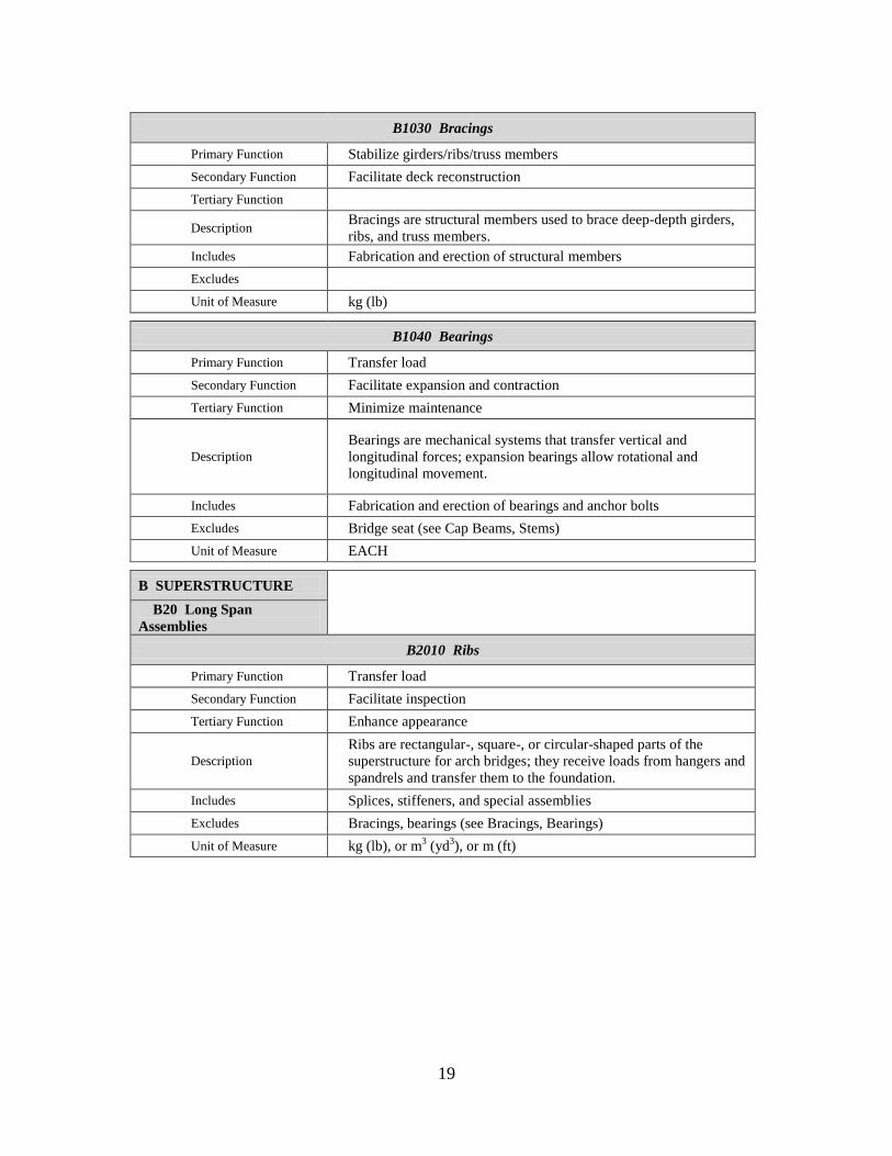
B1030 Bracings
Primary Function Stabilize girders/ribs/truss members
Secondary Function Facilitate deck reconstruction
Tertiary Function
Description Bracings are structural members used to brace deep-depth girders,
ribs, and truss members.
Includes Fabrication and erection of structural members
Excludes
Unit of Measure kg (lb)
B1040 Bearings
Primary Function Transfer load
Secondary Function Facilitate expansion and contraction
Tertiary Function Minimize maintenance
Description
Bearings are mechanical systems that transfer vertical and
longitudinal forces; expansion bearings allow rotational and
longitudinal movement.
Includes Fabrication and erection of bearings and anchor bolts
Excludes Bridge seat (see Cap Beams, Stems)
Unit of Measure EACH
B SUPERSTRUCTURE
B20 Long Span
Assemblies
B2010 Ribs
Primary Function Transfer load
Secondary Function Facilitate inspection
Tertiary Function Enhance appearance
Description
Ribs are rectangular-, square-, or circular-shaped parts of the
superstructure for arch bridges; they receive loads from hangers and
spandrels and transfer them to the foundation.
Includes Splices, stiffeners, and special assemblies
Excludes Bracings, bearings (see Bracings, Bearings)
Unit of Measure kg (lb), or m3 (yd
3), or m (ft)

20
B2020 Cables
Primary Function Transfer load
Secondary Function Enhance appearance
Tertiary Function
Description
Cables, made of steel wires bound together and draped over towers
to anchors at each cable end, receive through hangers the load from
the deck.
Includes Fabrication and installation of cables, cable support
Excludes Anchorage (see Anchorage)
Unit of Measure m (ft)
B2030 Hangers
Primary Function Transfer load
Secondary Function Ease replacement
Tertiary Function Enhance appearance
Description
Hangers are rods or strands that connect the deck to the ribs (arch
bridges) or the main cable (cable-stayed or suspension bridges);
they receive loads from the deck and transfer loads to the ribs or
main cable in tension.
Includes Splices (rod), strand assembly, protection
Excludes End connections (see Flexural Members and Ribs)
Unit of Measure m (ft)
B2040 Spandrels
Primary Function Transfer load
Secondary Function Ease replacement
Tertiary Function Enhance appearance
Description
Spandrels are concrete or steel members that connect the deck to
the ribs (arch bridges); they receive loads from the deck and
transfer loads to the ribs in compression. They are below the deck
and above the rib.
Includes Concrete or steel members, protection
Excludes End connections (see Flexural Members and Ribs)
Unit of Measure m (ft)
21
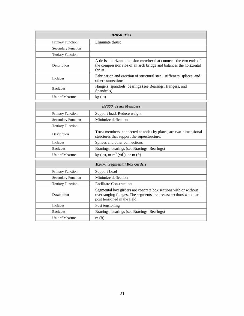
B2050 Ties
Primary Function Eliminate thrust
Secondary Function
Tertiary Function
Description
A tie is a horizontal tension member that connects the two ends of
the compression ribs of an arch bridge and balances the horizontal
thrust.
Includes Fabrication and erection of structural steel, stiffeners, splices, and
other connections
Excludes Hangers, spandrels, bearings (see Bearings, Hangers, and
Spandrels)
Unit of Measure kg (lb)
B2060 Truss Members
Primary Function Support load, Reduce weight
Secondary Function Minimize deflection
Tertiary Function
Description Truss members, connected at nodes by plates, are two-dimensional
structures that support the superstructure.
Includes Splices and other connections
Excludes Bracings, bearings (see Bracings, Bearings)
Unit of Measure kg (lb), or m3 (yd
3), or m (ft)
B2070 Segmental Box Girders
Primary Function Support Load
Secondary Function Minimize deflection
Tertiary Function Facilitate Construction
Description
Segmental box girders are concrete box sections with or without
overhanging flanges. The segments are precast sections which are
post tensioned in the field.
Includes Post tensioning
Excludes Bracings, bearings (see Bracings, Bearings)
Unit of Measure m (ft)

22
B SUPERSTRUCTURE
B30 Deck
B3010 Structural Surface
Primary Function Transfer load
Secondary Function Minimize maintenance
Tertiary Function Facilitate future expansion
Description The structural surface supports the wearing surface and traffic.
Includes Reinforcing, concrete, and finishing
Excludes Expansion joint assembly, parapet, barriers (see Expansion Joints,
Barriers, Drainage)
Unit of Measure m3 (yd
3) or EACH
B3020 Wearing Surface
Primary Function Protect structure, Guide traffic
Secondary Function Comfort riders
Tertiary Function Reduce maintenance
Description The wearing surface is the part of the road or rail system that comes
into contact with the vehicle or train car wheels.
Includes Concrete or asphalt overlay or rails, striping, and marking
Excludes
Unit of Measure m2 (ft
2)
C PROTECTION
C10 Structure Protection
C1010 Slope Walls
Primary Function Protect abutment
Secondary Function Prevent erosion
Tertiary Function Enhance appearance
Description Slope walls, made of stone, concrete, gravel, or gravel with asphalt
mix, support the sloped surface and protect the bridge abutment.
Includes Reinforcing, concrete, and finishing
Excludes Excavation and backfill (see Earthwork)
Unit of Measure m2 (ft
2)

23
C1020 Expansion Joints
Primary Function Facilitate expansion and contraction
Secondary Function Maintain smooth surface
Tertiary Function Facilitate replacement
Description Expansion joints allow expansion and contraction of the slab while
keeping the substructure stationary.
Includes Furnishing and installation of expansion joint support and
expansion joint
Excludes
Unit of Measure m (ft)
C1030 Protective Coats
Primary Function Protect structure
Secondary Function Minimize maintenance
Tertiary Function
Description Protective coats are paints, sealants, or preservatives that are
applied to concrete surfaces of the bridge.
Includes Minor repair work, cleaning surface, and coating
Excludes Major repair work to other bridge elements
Unit of Measure m2 (ft
2)
C1040 Sacrificial Beams
Primary Function Protect girders
Secondary Function Reduce maintenance
Tertiary Function
Description
Sacrificial beams have a lower clearance than the main beams to
ensure that excessive-height vehicles will hit the sacrificial beam
before impacting the main beams.
Includes Fabrication and erection of structural steel, stiffeners, splices, and
other connections
Excludes Bracings, bearings (see Bracings, Bearings)
Unit of Measure kg (lb)

24
C1050 Drainage Systems
Primary Function Minimize erosion
Secondary Function Protect traffic
Tertiary Function Protect structure
Description
Drainage systems are scuppers to drain the bridge deck, downspouts
to carry off the water from the scuppers, and buried drains behind
abutments and adjacent to sleeper slabs.
Includes Fabrication and installation of scuppers, drain tiles, drain pipes, and
related earthwork
Excludes Structural surface (see Structural Surface)
Unit of Measure EACH or m (ft)
C1060 Inspection and Maintenance Systems
Primary Function Facilitate inspection
Secondary Function Facilitate maintenance
Tertiary Function
Description These systems include platforms, railings, stairways, and hoist ways
to facilitate inspection and maintenance.
Includes Handrails or other type of barriers
Excludes
Unit of Measure m2 (ft
2)
C PROTECTION
C20 Traffic Protection
C2010 Barriers
Primary Function Separate traffic, Protect occupants
Secondary Function Protect structure
Tertiary Function Minimize maintenance
Description
Barriers are structures designed to: withstand forces due to crashes;
separate the opposing traffic; and protect bridge structures adjacent
to live traffic.
Includes Noise wall support, light pole support, traffic control support
Excludes
Unit of Measure m3 (yd
3)

25
C2020 Protective Shields
Primary Function Protect traffic (below)
Secondary Function
Tertiary Function
Description Protective shields are barriers below the bridge deck to protect
traffic below from falling objects.
Includes Membranes and supports designed to catch falling objects
Excludes
Unit of Measure m2 (ft
2)
C2030 Traffic Controls
Primary Function Manage Traffic
Secondary Function
Tertiary Function
Description Traffic controls are an assembly of signals, supports, and conduits
Includes Power source and related items
Excludes Base Support (see Barriers)
Unit of Measure EACH
C PROTECTION
C30 Other Protection
C3010 Lighting
Primary Function Protect traffic
Secondary Function Guide traffic
Tertiary Function Discourage vandalism
Description
Lighting is illumination from fixtures that provide vehicle traffic
direction, ship navigation direction, task lighting, and vandalism
discouragement.
Includes Fabrication and installation of mast, lights, base plates, and power
Excludes Base support (see Barriers)
Unit of Measure EACH
26
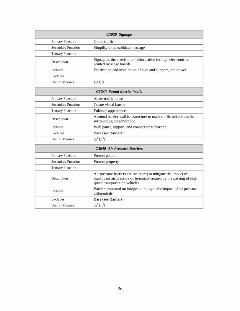
C3020 Signage
Primary Function Guide traffic
Secondary Function Simplify or consolidate message
Tertiary Function
Description Signage is the provision of information through electronic or
printed message boards.
Includes Fabrication and installation of sign and support, and power
Excludes
Unit of Measure EACH
C3030 Sound Barrier Walls
Primary Function Abate traffic noise
Secondary Function Create visual barrier
Tertiary Function Enhance appearance
Description A sound barrier wall is a structure to mask traffic noise from the
surrounding neighborhood.
Includes Wall panel, support, and connection to barrier
Excludes Base (see Barriers)
Unit of Measure m2 (ft
2)
C3040 Air Pressure Barriers
Primary Function Protect people
Secondary Function Protect property
Tertiary Function
Description
Air pressure barriers are structures to mitigate the impact of
significant air pressure differentials created by the passing of high
speed transportation vehicles.
Includes Barriers mounted on bridges to mitigate the impact of air pressure
differentials.
Excludes Base (see Barriers)
Unit of Measure m2 (ft
2)
27
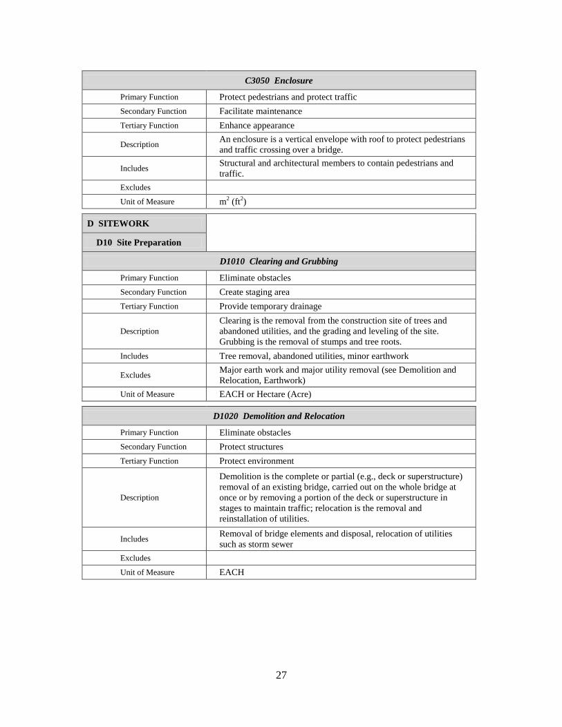
C3050 Enclosure
Primary Function Protect pedestrians and protect traffic
Secondary Function Facilitate maintenance
Tertiary Function Enhance appearance
Description An enclosure is a vertical envelope with roof to protect pedestrians
and traffic crossing over a bridge.
Includes Structural and architectural members to contain pedestrians and
traffic.
Excludes
Unit of Measure m2 (ft
2)
D SITEWORK
D10 Site Preparation
D1010 Clearing and Grubbing
Primary Function Eliminate obstacles
Secondary Function Create staging area
Tertiary Function Provide temporary drainage
Description
Clearing is the removal from the construction site of trees and
abandoned utilities, and the grading and leveling of the site.
Grubbing is the removal of stumps and tree roots.
Includes Tree removal, abandoned utilities, minor earthwork
Excludes Major earth work and major utility removal (see Demolition and
Relocation, Earthwork)
Unit of Measure EACH or Hectare (Acre)
D1020 Demolition and Relocation
Primary Function Eliminate obstacles
Secondary Function Protect structures
Tertiary Function Protect environment
Description
Demolition is the complete or partial (e.g., deck or superstructure)
removal of an existing bridge, carried out on the whole bridge at
once or by removing a portion of the deck or superstructure in
stages to maintain traffic; relocation is the removal and
reinstallation of utilities.
Includes Removal of bridge elements and disposal, relocation of utilities
such as storm sewer
Excludes
Unit of Measure EACH
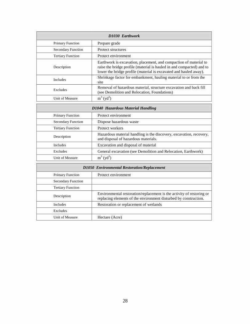
28
D1030 Earthwork
Primary Function Prepare grade
Secondary Function Protect structures
Tertiary Function Protect environment
Description
Earthwork is excavation, placement, and compaction of material to
raise the bridge profile (material is hauled in and compacted) and to
lower the bridge profile (material is excavated and hauled away).
Includes Shrinkage factor for embankment, hauling material to or from the
site
Excludes Removal of hazardous material, structure excavation and back fill
(see Demolition and Relocation, Foundations)
Unit of Measure m3 (yd
3)
D1040 Hazardous Material Handling
Primary Function Protect environment
Secondary Function Dispose hazardous waste
Tertiary Function Protect workers
Description Hazardous material handling is the discovery, excavation, recovery,
and disposal of hazardous materials.
Includes Excavation and disposal of material
Excludes General excavation (see Demolition and Relocation, Earthwork)
Unit of Measure m3 (yd
3)
D1050 Environmental Restoration/Replacement
Primary Function Protect environment
Secondary Function
Tertiary Function
Description Environmental restoration/replacement is the activity of restoring or
replacing elements of the environment disturbed by construction.
Includes Restoration or replacement of wetlands
Excludes
Unit of Measure Hectare (Acre)
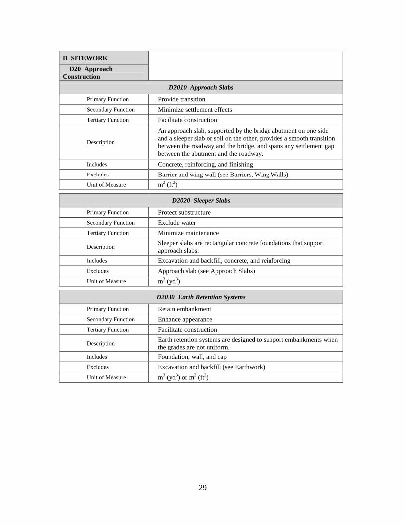
29
D SITEWORK
D20 Approach
Construction
D2010 Approach Slabs
Primary Function Provide transition
Secondary Function Minimize settlement effects
Tertiary Function Facilitate construction
Description
An approach slab, supported by the bridge abutment on one side
and a sleeper slab or soil on the other, provides a smooth transition
between the roadway and the bridge, and spans any settlement gap
between the abutment and the roadway.
Includes Concrete, reinforcing, and finishing
Excludes Barrier and wing wall (see Barriers, Wing Walls)
Unit of Measure m2 (ft
2)
D2020 Sleeper Slabs
Primary Function Protect substructure
Secondary Function Exclude water
Tertiary Function Minimize maintenance
Description Sleeper slabs are rectangular concrete foundations that support
approach slabs.
Includes Excavation and backfill, concrete, and reinforcing
Excludes Approach slab (see Approach Slabs)
Unit of Measure m3 (yd
3)
D2030 Earth Retention Systems
Primary Function Retain embankment
Secondary Function Enhance appearance
Tertiary Function Facilitate construction
Description Earth retention systems are designed to support embankments when
the grades are not uniform.
Includes Foundation, wall, and cap
Excludes Excavation and backfill (see Earthwork)
Unit of Measure m3 (yd
3) or m
2 (ft
2)

30

31
3 Summary and Recommendations for Further Research
3.1 Summary
This report presents a proposed UNIFORMAT II classification of bridge elements.
Elemental classifications differ from traditional product-related classifications because
their core concept is an element that performs a given function, regardless of the design
specification, construction method, or materials used. The proposed classification
represents a major revision and restructuring of ASTM Standard Classification E 2103, a
bridge-related standard classification first issued by ASTM in 2000. The original bridge
classification, E 2103, differed from the UNIFORMAT II elemental classification
hierarchy in several ways which limited its applicability. The major revisions to E 2103
described in this report will promote its relevance, understanding, and acceptance in the
bridge industry. Once approved and reissued by ASTM, the UNIFORMAT II Standard
Classification of Bridge Elements, E 2103, will provide the basis for a comprehensive
data set of bridge-related costs that will enable public and private decision makers to
choose more cost-effective solutions for the design and construction of new bridges and
the maintenance and repair of existing bridges across the Nation.
A set of alphanumeric designators for the proposed bridge classification is included.
Because many users are interested in constructing databases for use in cost analyses
associated with project planning, design, construction, maintenance and repair, and
condition assessment, alphanumeric designators provide the basis for compiling and
organizing cost data.
This report also includes a proposed list of sub-elements for bridges. The UNIFORMAT
II hierarchy consists of three levels: Level 1, Major Group Elements; Level 2, Group
Elements; and Level 3, Individual Elements. Thus, the core concept of an element
resides at Level 3. However, because elements are major components of a constructed
entity, there is often ambiguity of what exactly is included in an Individual Element and
what should be rightfully excluded from it. Because sub-elements can be tied into a work
breakdown structure, they significantly enhance the usefulness of an elemental
classification across all project participants throughout the lifecycle of bridges and other
constructed entities.
3.2 Recommendations for Further Research
The background work for this report uncovered several additional areas of research that
would be of value to government agencies, standards development organizations,
designers and constructors of physical infrastructure projects, and other stakeholders
concerned with the costs of designing and constructing new physical infrastructure and of
maintaining and repairing existing physical infrastructure across the Nation. Specifically,
four additional UNIFORMAT II classifications are proposed for development: (1)
tunnels; (2) highways; (3) railroads; and (4) water treatment and distribution. Each of
these proposed UNIFORMAT II classifications corresponds to a critical infrastructure
32
need identified in the American Society of Civil Engineers Report Card for America’s
Infrastructure.39
39
ASCE 2009 Report Card for America’s Infrastructure, op cit.
33
References
American Association of State Highway and Transportation Officials (AASHTO). 2008.
Bridging the Gap. Washington, DC: American Association of State Highway and
Transportation Officials.
American Society of Civil Engineers (ASCE). 2009. ASCE 2009 Report Card for
America’s Infrastructure. Reston, VA: American Society of Civil Engineers.
American Society of Civil Engineers (ASCE). 2009. Facts About Bridges. Reston, VA:
American Society of Civil Engineers.
ASTM International. “Classification for Allowance, Contingency and Reserve Sums in
Building Construction Estimating,” E 2168, Annual Book of ASTM Standards: 2010, Vol.
4.12. West Conshohocken, PA: ASTM International.
ASTM International. “Classification for Bridge Elements and Related Approach Work,”
E 2103, Annual Book of ASTM Standards: 2010, Vol. 4.12. West Conshohocken, PA:
ASTM International.
ASTM International. “Classification for Building Construction Field Requirements, and
Office Overhead and Profit,” E 2083, Annual Book of ASTM Standards: 2010, Vol. 4.11.
West Conshohocken, PA: ASTM International.
ASTM International. “Classification for Building Elements and Related Sitework—
UNIFORMAT II,” E 1557, Annual Book of ASTM Standards: 2010, Vol. 4.11. West
Conshohocken, PA: ASTM International.
ASTM International. “Classification for Cost Estimate Classification System,” E 2516,
Annual Book of ASTM Standards: 2010, Vol. 4.12. West Conshohocken, PA: ASTM
International.
ASTM International. “Guide for Developing a Cost-Effective Risk Mitigation Plan for
New and Existing Constructed Facilities,” E 2506, Annual Book of ASTM Standards:
2010, Vol. 4.12. West Conshohocken, PA: ASTM International.
ASTM International. “Guide for Selecting Techniques for Treating Uncertainty and Risk
in the Economic Evaluation of Buildings and Building Systems,” E 1369, Annual Book of
ASTM Standards: 2010, Vol. 4.11. West Conshohocken, PA: ASTM International.
ASTM International. “Guidelines for Developing UNIFORMAT II Standard
Classifications,” Working Paper. West Conshohocken, PA: ASTM International.
ASTM International. “Practice for Constructing FAST Diagrams and Performing
Function Analysis During Value Analysis Study,” E 2013, Annual Book of ASTM
Standards: 2010, Vol. 4.11. West Conshohocken, PA: ASTM International.

34
ASTM International. “Practice for Job Productivity Measurement,” E 2691, Annual Book
of ASTM Standards: 2010, Vol. 4.12. West Conshohocken, PA: ASTM International.
ASTM International. “Practice for Measuring Benefit-to-Cost and Savings-to-Investment
Ratios for Buildings and Building Systems,” E 964, Annual Book of ASTM Standards:
2010, Vol. 4.11. West Conshohocken, PA: ASTM International.
ASTM International. “Practice for Measuring Cost Risk of Buildings and Building
Systems,” E 1946, Annual Book of ASTM Standards: 2010, Vol. 4.11. West
Conshohocken, PA: ASTM International.
ASTM International. “Practice for Measuring Internal Rate of Return and Adjusted
Internal Rate of Return for Investments in Buildings and Building Systems,” E 1057,
Annual Book of ASTM Standards: 2010, Vol. 4.11. West Conshohocken, PA: ASTM
International.
ASTM International. “Practice for Measuring Life-Cycle Costs of Buildings and Building
Systems,” E 917, Annual Book of ASTM Standards: 2010, Vol. 4.11. West
Conshohocken, PA: ASTM International.
ASTM International. “Practice for Measuring Net Benefits and Net Savings for
Investments in Buildings and Building Systems,” E 1074, Annual Book of ASTM
Standards: 2010, Vol. 4.11. West Conshohocken, PA: ASTM International.
ASTM International. “Practice for Measuring Payback for Investments in Buildings and
Building Systems,” E 1121, Annual Book of ASTM Standards: 2010, Vol. 4.11. West
Conshohocken, PA: ASTM International.
ASTM International. “Practice for Performing and Reporting Cost Analysis During the
Design Phase of a Project,” E 1804, Annual Book of ASTM Standards: 2010, Vol. 4.11.
West Conshohocken, PA: ASTM International.
ASTM International. “Practice for Performing Value Analysis (VA) of Buildings and
Building Systems,” E 1699, Annual Book of ASTM Standards: 2010, Vol. 4.11. West
Conshohocken, PA: ASTM International.
ASTM International. “Practice for Presentation Format of Elemental Cost Estimates,
Summaries, and Analyses,” E 2514, Annual Book of ASTM Standards: 2010, Vol. 4.12.
West Conshohocken, PA: ASTM International.
Bowen, Brian, Charette, Robert P., and Marshall, Harold E. 1992. UNIFORMAT II: A
Recommended Classification for Building Elements and Related Sitework, NIST Special
Publication 841. Gaithersburg, MD: National Institute of Standards and Technology.

35
Charette, Robert P., and Marshall, Harold E. 1999. UNIFORMAT II: Elemental
Classification for Building Specifications, Cost Estimating, and Cost Analysis, NISTIR
6389. Gaithersburg, MD: National Institute of Standards and Technology.
Hanscomb Associates, Inc. 1975. Automated Cost Control and Estimating System.
Washington, DC: General Services Administration.
Illinois Department of Transportation (IDOT). 2011. IDOT Bridge Standards.40
Springfield, IL: Illinois Department of Transportation.
Royal Institute of Chartered Surveyors (RICS). 1969. Standard Form of Cost Analysis.
London, England: The Building Cost Information Service.
40
Diagrams from the IDOT Bridge Standards document reproduced in this report were in effect on March
25, 2011; current IDOT Bridge Standards are available at: http://www.dot.il.gov/bridges/bscadd2.html.

36
37
Appendix A Suggested Sub-Classifications of Bridge Elements
This appendix presents suggested sub-classifications of bridge elements. The sub-
classifications expand the Level 3 Individual Elements into their constituent parts. These
constituent parts include a Level 4 for all Individual Elements and, where necessary, a
Level 5 (i.e., subdivisions of Level 4).
The suggested sub-classifications are presented in Table A.1. Table A.1 is laid out in a
six column format. The first column lists the Level 1 Major Group Elements. The
second column lists the Level 2 Group Elements. The third column lists the Level 3
Individual Elements. The fourth column lists the Level 4 Sub-Elements associated with
each Level 3 Individual Element. The fifth column lists any Level 5 Sub-Elements
associated with a Level 4 Sub-Element. Where appropriate, the Level 5 Sub-Elements
are listed in the normal chronological order of construction. The sixth column lists any
Level 5 Field Requirements that are both significant in their cost and specific to a Level 4
Sub-Element (e.g., Formwork associated with Spread Footings).
Alphanumeric designators are included for all Level 4 Sub-Elements, Level 5 Sub-
Elements, and Level 5 Field Requirements. It is anticipated that the alphanumeric
designators will be useful in structuring cost manuals and in recording construction,
operating, and maintenance costs in computer databases.
The alphanumeric designators use the Level 3 Individual Element character string as their
reference point. For example, the first Level 4 Sub-Element associated with the A1010
Foundations Level 3 Individual Element is A101010 Spread Footings. Additional Level
4 Sub-Elements associated with A1010 Foundations are: A101020 Piles and A101030
Drilled Shafts. For Level 5 Sub-Elements, the alphanumeric designator uses the Level 4
Sub-Element as their reference point. For example, the first Level 5 Sub-Element
associated with the A101010 Spread Footings Level 4 Sub-Element is A10101010
Excavation. Additional Level 5 Sub-Elements associated with A101010 Spread Footings
are: A10101020 Reinforcement; A10101030 Placement; and A10101040 Backfilling.
Spread Footings have a significant field requirement associated with them due to
Formwork. The alphanumeric designator for Field Requirements includes an X to tie it
back to Table 1 in E 2083, Standard Classification for Building Construction Field
Requirements and Office Overhead and Profit. For example, the Level 5 Field
Requirement associated with the A101010 Spread Footings Level 4 Sub-Element is
A101010X2 Formwork. If Spread Footings are installed in a waterway, a Cofferdam will
be required before Excavation can commence. In this case, the Level 5 Field
Requirement associated with the A101010 Spread Footings Level 4 Sub-Element is
A101010X1 Cofferdam.

38
Table A.1 Suggested Sub-Classifications of Bridge Elements
Level 1
Major Group
Elements
Level 2
Group Elements
Level 3
Individual Elements
Level 4
Sub-Elements
Level 5
Sub-Elements
Level 5
Field Requirements
A Substructure A10 Piers A1010 Foundations A101010 Spread Footings A101010X1 Cofferdam
A10101010 Excavation
A101010X2 Formwork
A10101020 Reinforcement
A10101030 Placement
A10101040 Backfilling
A101020 Piles A10102010 Test Piles
A10102020 Piles
A10102030 Pile Cap
A101030 Drilled Shafts A101030X1 Temporary Casing
A10103010 Permanent
Casing
A10103020 Rock Socket
A10103030 Bell
A10103040 Reinforcement
A10103050 Placement
A10103060 Cap
A1020 Walls A102010 Cast-in-Place
Concrete
A102010X1 Formwork
A10201020 Reinforcement
A10201030 Placement
A10201040 Finishing
A10201050 Coating
A102020 Precast Concrete A10202010 Fabrication
A10202020 Erection
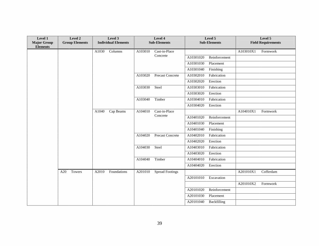
39
Level 1
Major Group
Elements
Level 2
Group Elements
Level 3
Individual Elements
Level 4
Sub-Elements
Level 5
Sub-Elements
Level 5
Field Requirements
A1030 Columns A103010 Cast-in-Place
Concrete
A103010X1 Formwork
A10301020 Reinforcement
A10301030 Placement
A10301040 Finishing
A103020 Precast Concrete A10302010 Fabrication
A10302020 Erection
A103030 Steel A10303010 Fabrication
A10303020 Erection
A103040 Timber A10304010 Fabrication
A10304020 Erection
A1040 Cap Beams A104010 Cast-in-Place
Concrete
A104010X1 Formwork
A10401020 Reinforcement
A10401030 Placement
A10401040 Finishing
A104020 Precast Concrete A10402010 Fabrication
A10402020 Erection
A104030 Steel A10403010 Fabrication
A10403020 Erection
A104040 Timber A10404010 Fabrication
A10404020 Erection
A20 Towers A2010 Foundations A201010 Spread Footings A201010X1 Cofferdam
A20101010 Excavation
A201010X2 Formwork
A20101020 Reinforcement
A20101030 Placement
A20101040 Backfilling

40
Level 1
Major Group
Elements
Level 2
Group Elements
Level 3
Individual Elements
Level 4
Sub-Elements
Level 5
Sub-Elements
Level 5
Field Requirements
A201020 Pile Foundations A20102010 Test Piles
A20102020 Piles
A20102030 Pile Cap
A201030 Drilled Shafts A201030X1 Temporary Casing
A20103010 Permanent
Casing
A20103020 Rock Socket
A20103030 Bell
A20103040 Reinforcement
A20103050 Placement
A20103060 Cap
A2020 Walls A202010 Cast-in-Place
Concrete
A202010X1 Formwork
A20201010 Reinforcement
A20201020 Placement
A20201030 Finishing
A20201040 Coating
A202020 Precast Concrete A20202010 Fabrication
A20202020 Erection
A2030 Columns A203010 Cast-in-Place
Concrete
A203010X1 Formwork
A20301010 Reinforcement
A20301020 Placement
A20301030 Finishing
A203020 Precast Concrete A20302010 Fabrication
A20302020 Erection
A203030 Steel A20303010 Fabrication
A20303020 Erection
A203040 Timber A20304010 Fabrication
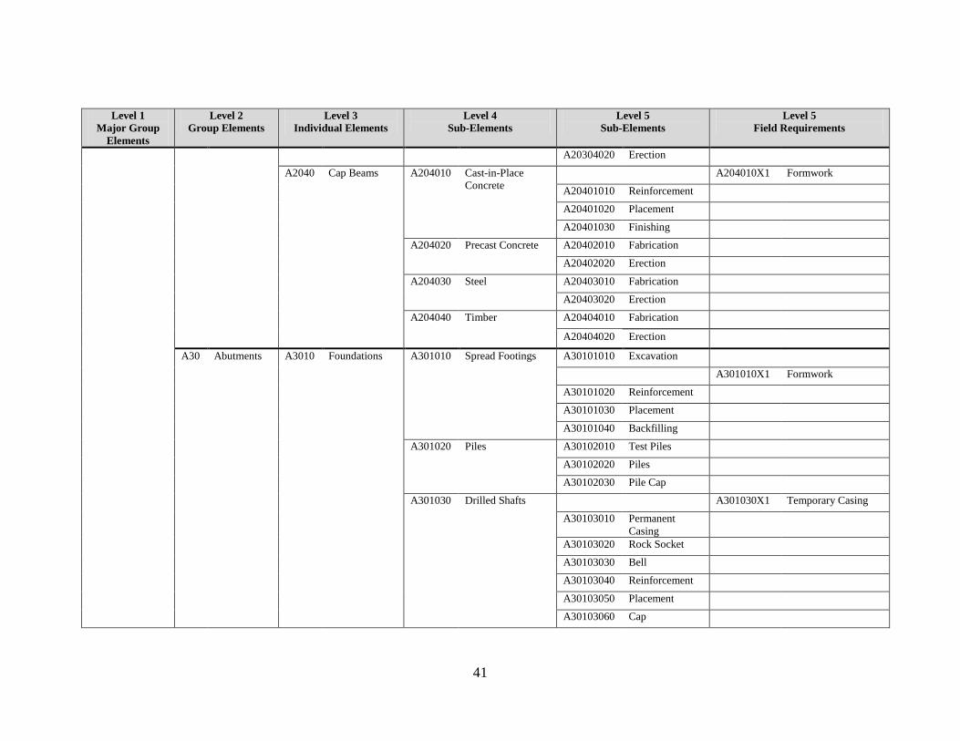
41
Level 1
Major Group
Elements
Level 2
Group Elements
Level 3
Individual Elements
Level 4
Sub-Elements
Level 5
Sub-Elements
Level 5
Field Requirements
A20304020 Erection
A2040 Cap Beams A204010 Cast-in-Place
Concrete
A204010X1 Formwork
A20401010 Reinforcement
A20401020 Placement
A20401030 Finishing
A204020 Precast Concrete A20402010 Fabrication
A20402020 Erection
A204030 Steel A20403010 Fabrication
A20403020 Erection
A204040 Timber A20404010 Fabrication
A20404020 Erection
A30 Abutments A3010 Foundations A301010 Spread Footings A30101010 Excavation
A301010X1 Formwork
A30101020 Reinforcement
A30101030 Placement
A30101040 Backfilling
A301020 Piles A30102010 Test Piles
A30102020 Piles
A30102030 Pile Cap
A301030 Drilled Shafts A301030X1 Temporary Casing
A30103010 Permanent
Casing
A30103020 Rock Socket
A30103030 Bell
A30103040 Reinforcement
A30103050 Placement
A30103060 Cap
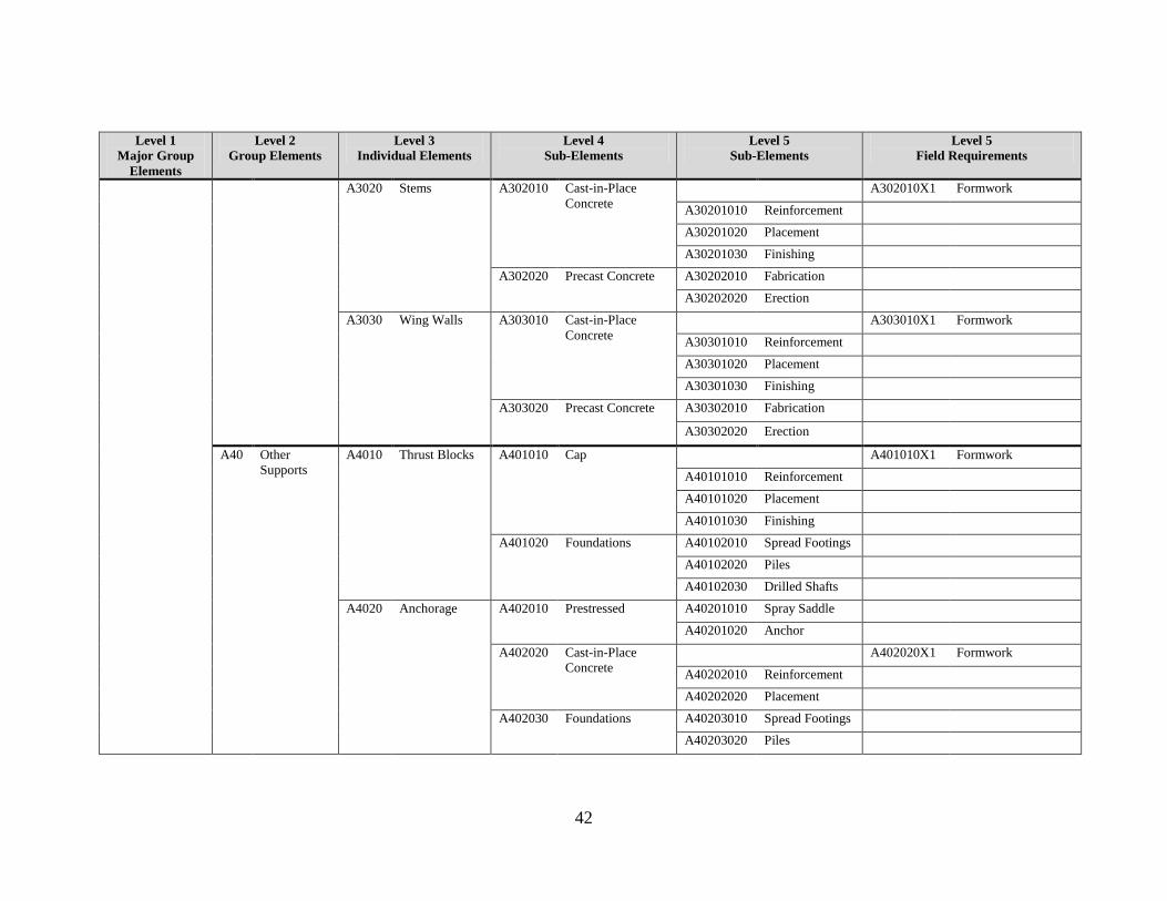
42
Level 1
Major Group
Elements
Level 2
Group Elements
Level 3
Individual Elements
Level 4
Sub-Elements
Level 5
Sub-Elements
Level 5
Field Requirements
A3020 Stems A302010 Cast-in-Place
Concrete
A302010X1 Formwork
A30201010 Reinforcement
A30201020 Placement
A30201030 Finishing
A302020 Precast Concrete A30202010 Fabrication
A30202020 Erection
A3030 Wing Walls A303010 Cast-in-Place
Concrete
A303010X1 Formwork
A30301010 Reinforcement
A30301020 Placement
A30301030 Finishing
A303020 Precast Concrete A30302010 Fabrication
A30302020 Erection
A40 Other
Supports
A4010 Thrust Blocks A401010 Cap A401010X1 Formwork
A40101010 Reinforcement
A40101020 Placement
A40101030 Finishing
A401020 Foundations A40102010 Spread Footings
A40102020 Piles
A40102030 Drilled Shafts
A4020 Anchorage A402010 Prestressed A40201010 Spray Saddle
A40201020 Anchor
A402020 Cast-in-Place
Concrete
A402020X1 Formwork
A40202010 Reinforcement
A40202020 Placement
A402030 Foundations A40203010 Spread Footings
A40203020 Piles
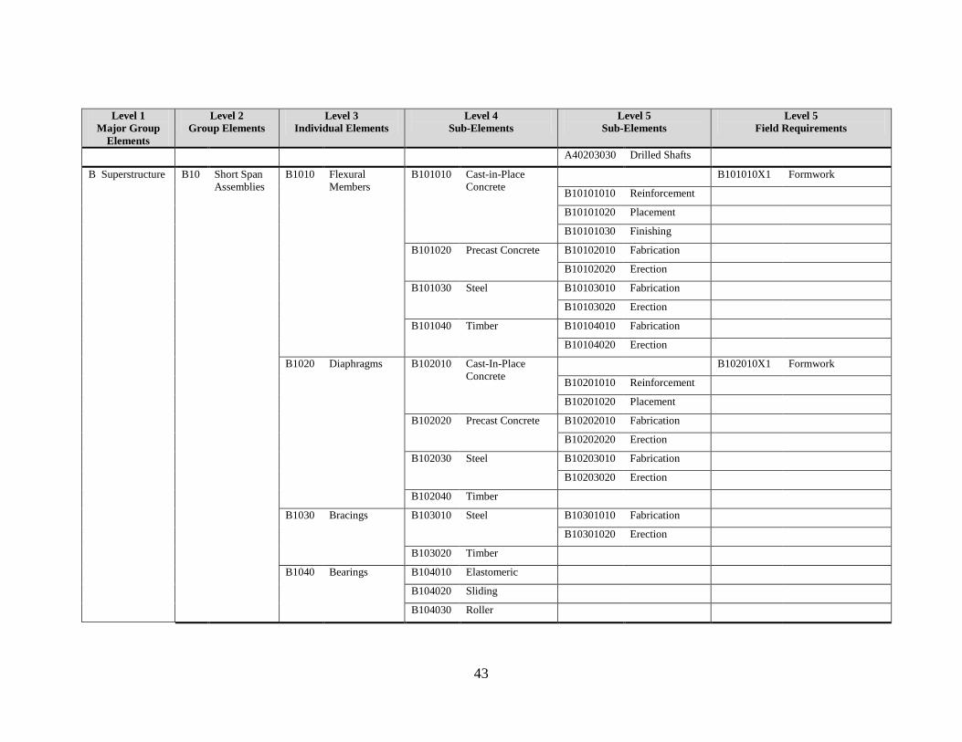
43
Level 1
Major Group
Elements
Level 2
Group Elements
Level 3
Individual Elements
Level 4
Sub-Elements
Level 5
Sub-Elements
Level 5
Field Requirements
A40203030 Drilled Shafts
B Superstructure B10 Short Span
Assemblies
B1010 Flexural
Members
B101010 Cast-in-Place
Concrete
B101010X1 Formwork
B10101010 Reinforcement
B10101020 Placement
B10101030 Finishing
B101020 Precast Concrete B10102010 Fabrication
B10102020 Erection
B101030 Steel B10103010 Fabrication
B10103020 Erection
B101040 Timber B10104010 Fabrication
B10104020 Erection
B1020 Diaphragms B102010 Cast-In-Place
Concrete
B102010X1 Formwork
B10201010 Reinforcement
B10201020 Placement
B102020 Precast Concrete B10202010 Fabrication
B10202020 Erection
B102030 Steel B10203010 Fabrication
B10203020 Erection
B102040 Timber
B1030 Bracings B103010 Steel B10301010 Fabrication
B10301020 Erection
B103020 Timber
B1040 Bearings B104010 Elastomeric
B104020 Sliding
B104030 Roller
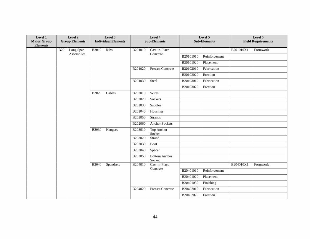
44
Level 1
Major Group
Elements
Level 2
Group Elements
Level 3
Individual Elements
Level 4
Sub-Elements
Level 5
Sub-Elements
Level 5
Field Requirements
B20 Long Span
Assemblies
B2010 Ribs B201010 Cast-in-Place
Concrete
B201010X1 Formwork
B20101010 Reinforcement
B20101020 Placement
B201020 Precast Concrete B20102010 Fabrication
B20102020 Erection
B201030 Steel B20103010 Fabrication
B20103020 Erection
B2020 Cables B202010 Wires
B202020 Sockets
B202030 Saddles
B202040 Housings
B202050 Strands
B202060 Anchor Sockets
B2030 Hangers B203010 Top Anchor
Socket
B203020 Strand
B203030 Boot
B203040 Spacer
B203050 Bottom Anchor
Socket
B2040 Spandrels B204010 Cast-in-Place
Concrete
B204010X1 Formwork
B20401010 Reinforcement
B20401020 Placement
B20401030 Finishing
B204020 Precast Concrete B20402010 Fabrication
B20402020 Erection
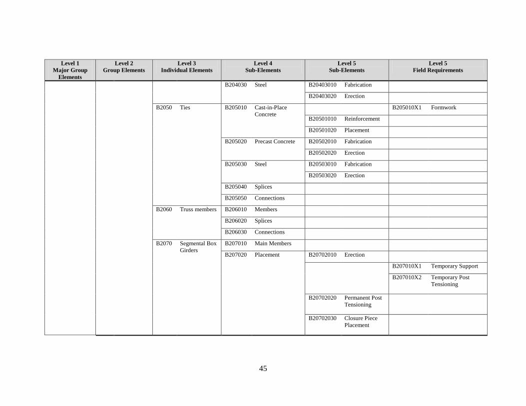
45
Level 1
Major Group
Elements
Level 2
Group Elements
Level 3
Individual Elements
Level 4
Sub-Elements
Level 5
Sub-Elements
Level 5
Field Requirements
B204030 Steel B20403010 Fabrication
B20403020 Erection
B2050 Ties B205010 Cast-in-Place
Concrete
B205010X1 Formwork
B20501010 Reinforcement
B20501020 Placement
B205020 Precast Concrete B20502010 Fabrication
B20502020 Erection
B205030 Steel B20503010 Fabrication
B20503020 Erection
B205040 Splices
B205050 Connections
B2060 Truss members B206010 Members
B206020 Splices
B206030 Connections
B2070 Segmental Box
Girders
B207010 Main Members
B207020 Placement B20702010 Erection
B207010X1 Temporary Support
B207010X2 Temporary Post
Tensioning
B20702020 Permanent Post
Tensioning
B20702030 Closure Piece
Placement
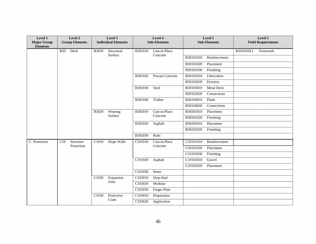
46
Level 1
Major Group
Elements
Level 2
Group Elements
Level 3
Individual Elements
Level 4
Sub-Elements
Level 5
Sub-Elements
Level 5
Field Requirements
B30 Deck B3010 Structural
Surface
B301010 Cast-in-Place
Concrete
B301010X1 Formwork
B30101010 Reinforcement
B30101020 Placement
B30101030 Finishing
B301020 Precast Concrete B30102010 Fabrication
B30102020 Erection
B301030 Steel B30103010 Metal Deck
B30103020 Connections
B301040 Timber B30104010 Plank
B30104020 Connections
B3020 Wearing
Surface
B302010 Cast-in-Place
Concrete
B30201010 Placement
B30201020 Finishing
B302020 Asphalt B30202010 Placement
B30202020 Finishing
B302030 Rails
C Protection C10 Structure
Protection
C1010 Slope Walls C101010 Cast-in-Place
Concrete
C10101010 Reinforcement
C10101020 Placement
C10101030 Finishing
C101020 Asphalt C10102010 Gravel
C10102020 Placement
C101030 Stone
C1020 Expansion
Joint
C102010 Strip-Seal
C102020 Modular
C102030 Finger Plate
C1030 Protective
Coats
C103010 Preparation
C103020 Application

47
Level 1
Major Group
Elements
Level 2
Group Elements
Level 3
Individual Elements
Level 4
Sub-Elements
Level 5
Sub-Elements
Level 5
Field Requirements
C1040 Sacrificial
Beams
C104010 Fabrication
C104020 Erection
C1050 Drainage
System
C105010 Scuppers
C105020 Drain Pipes
C105030 Buried Drains C10503010 Pipe
C10503020 Head Wall
C10503030 End Walls
C1060 Inspection and
Maintenance
Systems
C106010 Hangers
C106020 Beams
C106030 Platform
C106040 Railing
C106050 Connections
C20 Traffic
Protection
C2010 Barriers C201010 Parapet
C201020 Railing
C201030 Glare Screen
C201040 Median
C201050 Curb
C201060 Guardrail
C201070 Screen
C2020 Protective
Shields
C202010 Fabrication
C202020 Erection
C2030 Traffic
Controls
C203010 Signals
C203020 Arms
C203030 Mast
C203040 Base Plate
C203050 Conduits

48
Level 1
Major Group
Elements
Level 2
Group Elements
Level 3
Individual Elements
Level 4
Sub-Elements
Level 5
Sub-Elements
Level 5
Field Requirements
C30 Other
Protection
C3010 Lighting C301010 Lights
C301020 Arms
C301030 Mast
C301040 Base Plate
C301050 Conduits
C3020 Signage C302010 Sign Board
C302020 Support
C302030 Lights
C302040 Conduits
C3030 Sound Barrier
Walls
C303010 Panels
C303020 Support
C303030 Connections
C3040 Air Pressure
Barriers
C304010 Panels
C304020 Support
C304030 Connections
C3050 Enclosure C305010 Vertical Envelope
C305020 Roof
D Sitework D10 Site
Preparation
D1010 Clearing and
Grubbing
D101010 Clearing
D101020 Grubbing
D1020 Demolition and
Relocation
D102010 Structures
D102020 Utilities
D102030 Trees
D1030 Earthwork D103010 Cut
D103020 Fill
D1040 Hazardous
Material
Handling
D104010 Excavation
D104020 Disposal
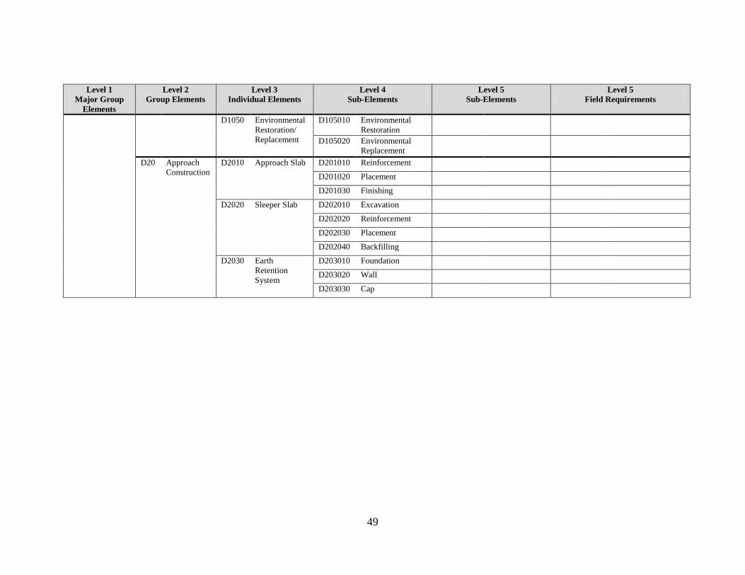
49
Level 1
Major Group
Elements
Level 2
Group Elements
Level 3
Individual Elements
Level 4
Sub-Elements
Level 5
Sub-Elements
Level 5
Field Requirements
D1050 Environmental
Restoration/
Replacement
D105010 Environmental
Restoration
D105020 Environmental
Replacement
D20 Approach
Construction
D2010 Approach Slab D201010 Reinforcement
D201020 Placement
D201030 Finishing
D2020 Sleeper Slab D202010 Excavation
D202020 Reinforcement
D202030 Placement
D202040 Backfilling
D2030 Earth
Retention
System
D203010 Foundation
D203020 Wall
D203030 Cap

50

51
Appendix B An Illustrated Guide to the Proposed UNIFORMAT II
Classification of Bridge Elements
This appendix is designed as an illustrated guide to the proposed UNIFORMAT II
classification of bridge elements. The appendix includes diagrams, engineering
drawings, and, where appropriate, photographs to identify the appearance of each element
and how it fits into the overall framework.
The figures presented in this appendix are organized around the proposed UNIFORMAT
II hierarchy. Figures are arranged by Major Group Element and Group Element, with
Individual Elements clearly marked in the diagram, engineering drawing, or photograph.
For each Major Group Element, the Group Elements are presented in the sequence they
are listed in Table 2.2. For each Group Element, the Individual Elements are labeled in
one of more figures associated with that Group element. In some case, Sub-Elements are
also listed.
Figure B.1 Major Group Elements: A Substructure, B Superstructure
Source: Illinois Department of Transportation

52
Figure B.2 Group Elements: A10 Piers
Source: Illinois Department of Transportation
Figure B.3 Group Elements: A10 Piers
Source: Alfred Benesch & Company

53
Figure B.4 Individual Elements: A1010 Foundations (Field Requirements:
A101010X1 (Cofferdam))
Source: Alfred Benesch & Company
Figure B.5 Individual Elements: A1010 Foundations (Sub-Elements: A101010
Spread Footings (Excavation))
Source: Alfred Benesch & Company
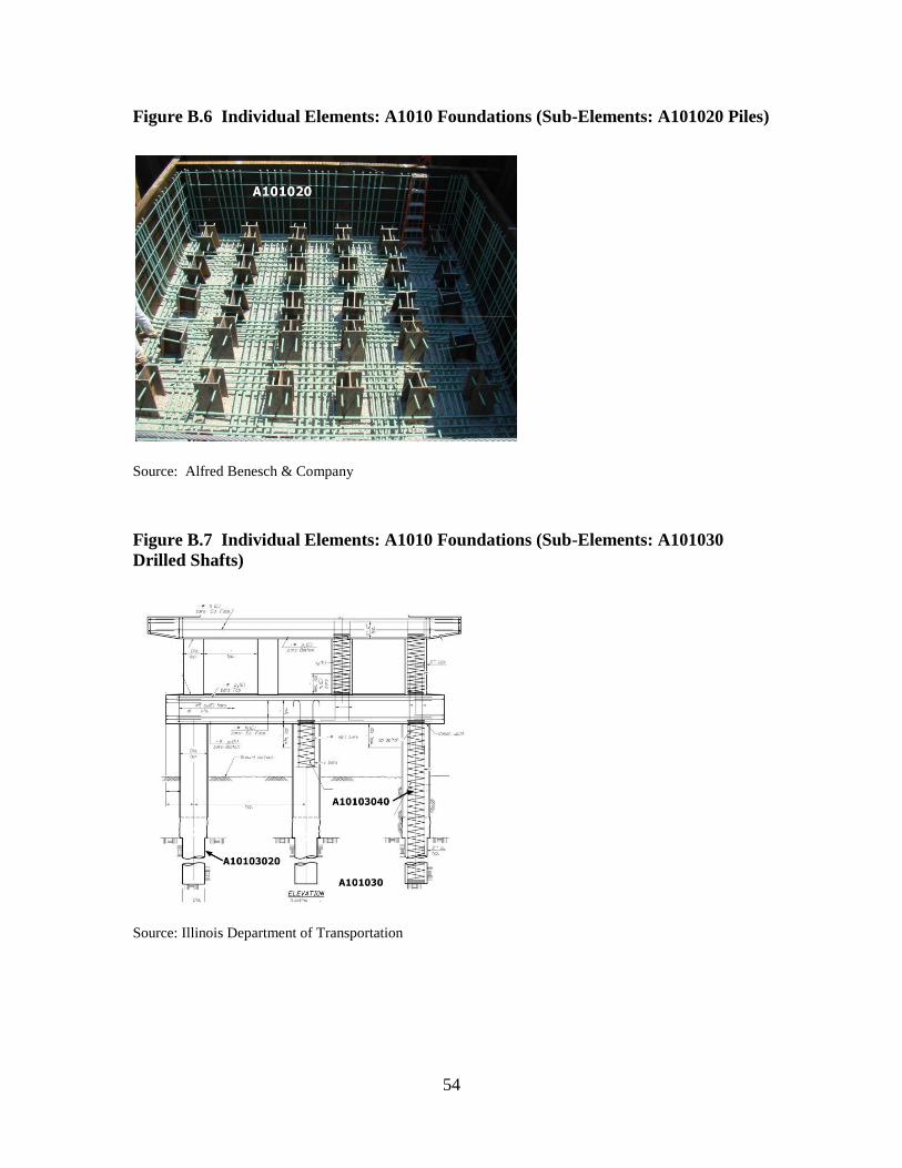
54
Figure B.6 Individual Elements: A1010 Foundations (Sub-Elements: A101020 Piles)
Source: Alfred Benesch & Company
Figure B.7 Individual Elements: A1010 Foundations (Sub-Elements: A101030
Drilled Shafts)
Source: Illinois Department of Transportation

55
Figure B.8 Individual Elements: A1020 Walls, A1030 Columns, A1040 Cap Beams
Source: Alfred Benesch & Company
Figure B.9 Individual Elements: A1040 Cap Beams (Sub-Elements: A10401020
Reinforcement)
Source: Alfred Benesch & Company

56
Figure B.10 Individual Elements: A1040 Cap Beams
Source: Alfred Benesch & Company
Figure B.11 Group Elements: A20 Towers
Source: Alfred Benesch & Company
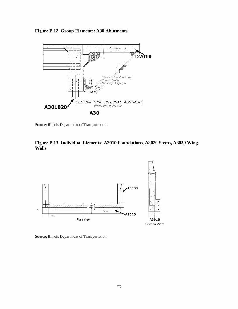
57
Figure B.12 Group Elements: A30 Abutments
Source: Illinois Department of Transportation
Figure B.13 Individual Elements: A3010 Foundations, A3020 Stems, A3030 Wing
Walls
Source: Illinois Department of Transportation

58
Figure B.14 Individual Elements: A3010 Foundations (Sub-Elements: A301020
Piles, A30102030 Pile Cap)
Source: Illinois Department of Transportation
Figure B.15 Individual Elements: A3020 Stems
Source: Alfred Benesch & Company

59
Figure B.16 Individual Elements: A3030 Wing Walls
Source: Alfred Benesch & Company
Figure B.17 Group Elements: A40 Other Supports (Individual Elements: A4010
Thrust Blocks)
Source: Alfred Benesch & Company

60
Figure B.18 Individual Elements: A4010 Thrust Blocks (Sub-Elements: A401020
Foundations (A40102020 Piles))
Source: Alfred Benesch & Company
Figure B.19 Group Elements: B10 Short Span Assemblies (Individual Elements:
B1010 Flexural Member, B1020 Diaphragms), B30 Deck
Source: Illinois Department of Transportation

61
Figure B.20 Individual Elements: B1010 Flexural Members, B1020 Diaphragms
Source: Illinois Department of Transportation
Figure B.21 Individual Elements: B1020 Diaphragms
Source: Alfred Benesch & Company

62
Figure B.22 Individual Elements: B1030 Bracings
Source: Illinois Department of Transportation
Figure B.23 Individual Elements: B1030 Bracings
Source: Alfred Benesch & Company
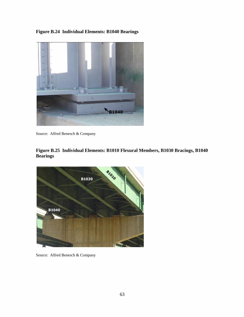
63
Figure B.24 Individual Elements: B1040 Bearings
Source: Alfred Benesch & Company
Figure B.25 Individual Elements: B1010 Flexural Members, B1030 Bracings, B1040
Bearings
Source: Alfred Benesch & Company
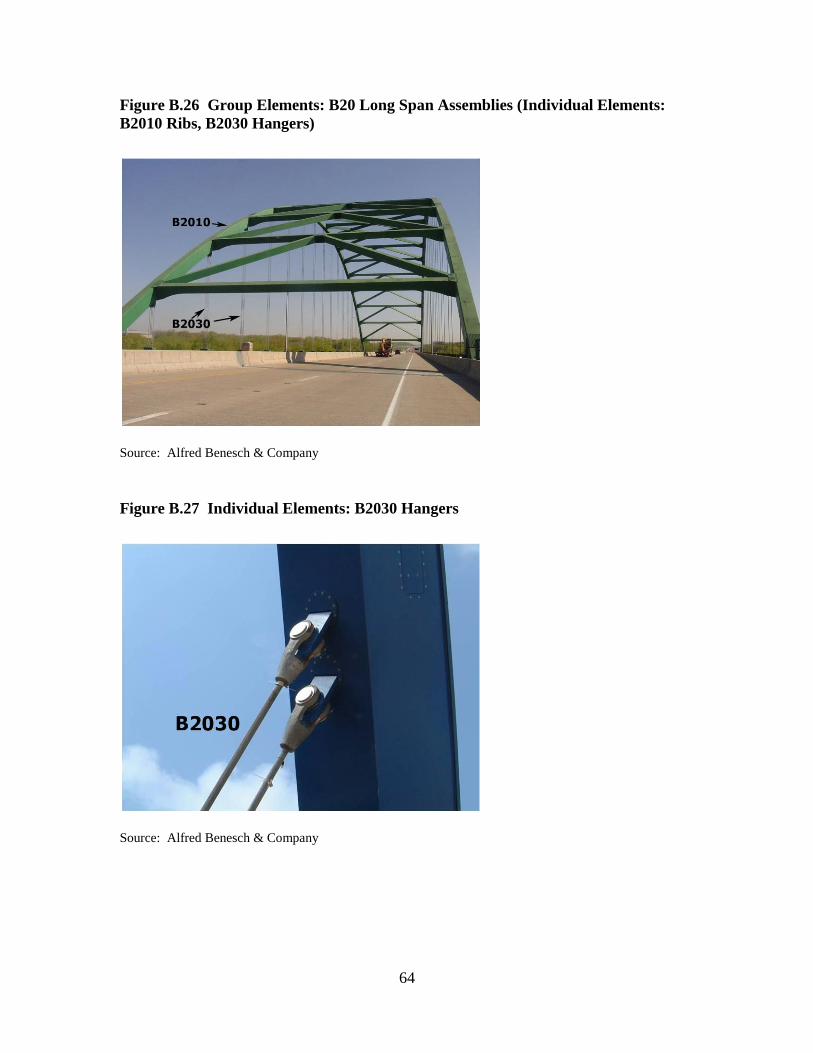
64
Figure B.26 Group Elements: B20 Long Span Assemblies (Individual Elements:
B2010 Ribs, B2030 Hangers)
Source: Alfred Benesch & Company
Figure B.27 Individual Elements: B2030 Hangers
Source: Alfred Benesch & Company
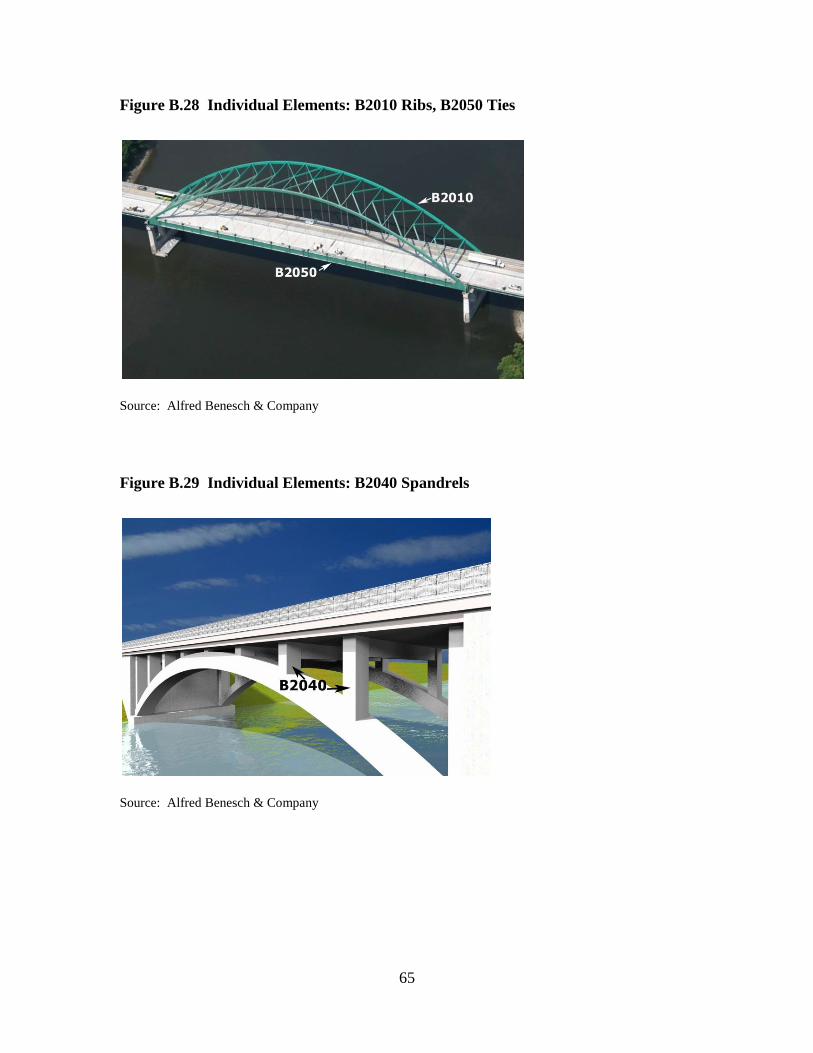
65
Figure B.28 Individual Elements: B2010 Ribs, B2050 Ties
Source: Alfred Benesch & Company
Figure B.29 Individual Elements: B2040 Spandrels
Source: Alfred Benesch & Company
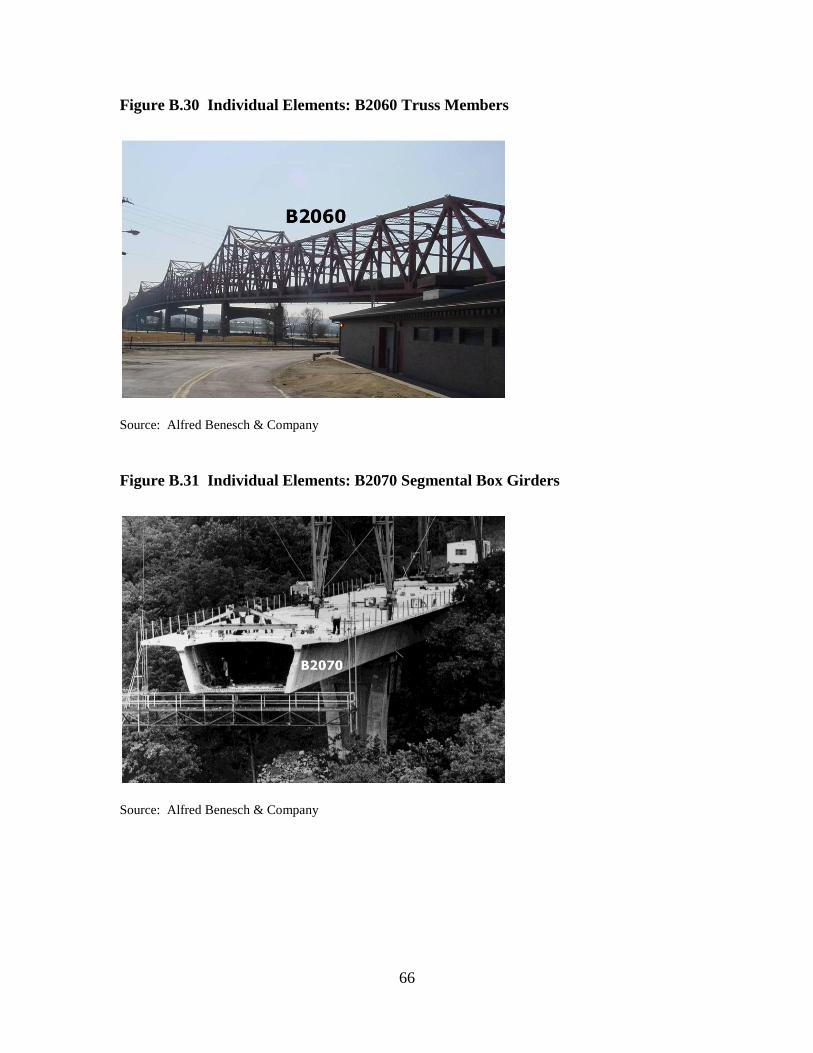
66
Figure B.30 Individual Elements: B2060 Truss Members
Source: Alfred Benesch & Company
Figure B.31 Individual Elements: B2070 Segmental Box Girders
Source: Alfred Benesch & Company
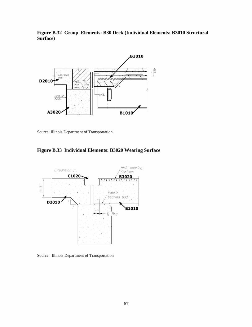
67
Figure B.32 Group Elements: B30 Deck (Individual Elements: B3010 Structural
Surface)
Source: Illinois Department of Transportation
Figure B.33 Individual Elements: B3020 Wearing Surface
Source: Illinois Department of Transportation
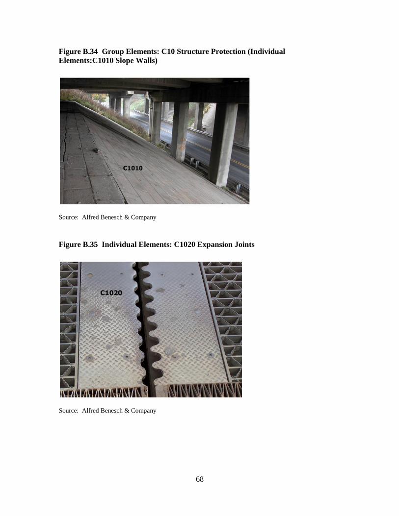
68
Figure B.34 Group Elements: C10 Structure Protection (Individual
Elements:C1010 Slope Walls)
Source: Alfred Benesch & Company
Figure B.35 Individual Elements: C1020 Expansion Joints
Source: Alfred Benesch & Company
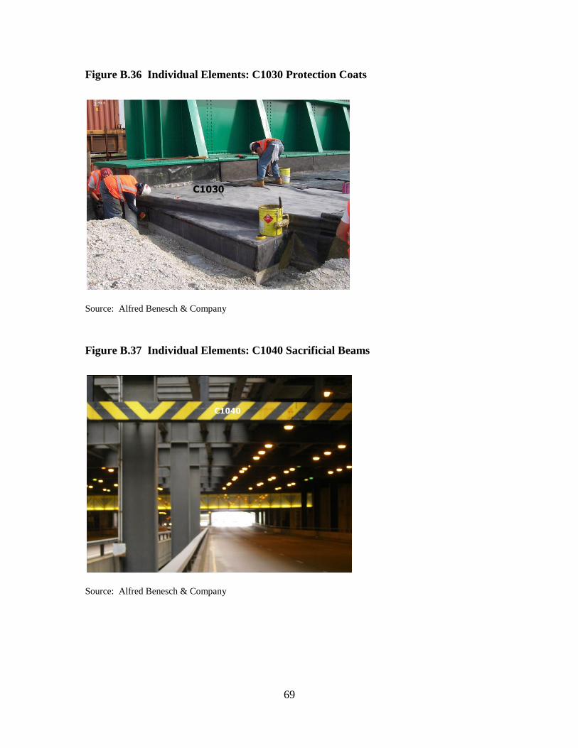
69
Figure B.36 Individual Elements: C1030 Protection Coats
Source: Alfred Benesch & Company
Figure B.37 Individual Elements: C1040 Sacrificial Beams
Source: Alfred Benesch & Company
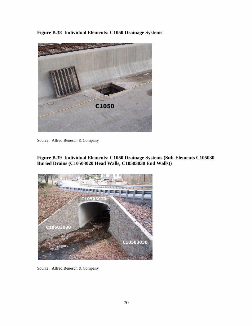
70
Figure B.38 Individual Elements: C1050 Drainage Systems
Source: Alfred Benesch & Company
Figure B.39 Individual Elements: C1050 Drainage Systems (Sub-Elements C105030
Buried Drains (C10503020 Head Walls, C10503030 End Walls))
Source: Alfred Benesch & Company

71
Figure B.40 Individual Elements: C1060 Inspection and Maintenance Systems
Source: Alfred Benesch & Company
Figure B.41 Individual Elements: C2010 Barriers
Source: Illinois Department of Transportation

72
Figure B.42 Group Elements: C30 Other Protection (Individual Elements: C3010
Lighting)
Source: Illinois Department of Transportation
Figure B.43 Individual Elements: C3010 Lighting, C3020 Signage
Source: Alfred Benesch & Company
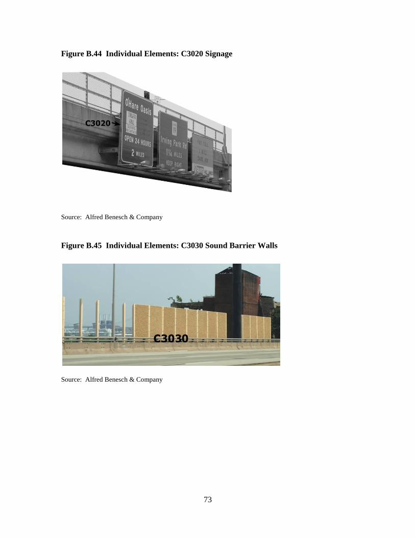
73
Figure B.44 Individual Elements: C3020 Signage
Source: Alfred Benesch & Company
Figure B.45 Individual Elements: C3030 Sound Barrier Walls
Source: Alfred Benesch & Company
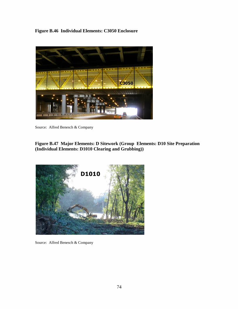
74
Figure B.46 Individual Elements: C3050 Enclosure
Source: Alfred Benesch & Company
Figure B.47 Major Elements: D Sitework (Group Elements: D10 Site Preparation
(Individual Elements: D1010 Clearing and Grubbing))
Source: Alfred Benesch & Company

75
Figure B.48 Individual Elements: D1010 Clearing and Grubbing (Sub-Element
D101010 Clearing (Tree Removal))
Source: Alfred Benesch & Company
Figure B.49 Group Elements: D10 Site Preparation (Individual Elements: D1020
Demolition and Relocation)
Source: Alfred Benesch & Company

76
Figure B.50 Individual Elements: D1020 Demolition and Relocation
Source: Alfred Benesch & Company
Figure B.51 Individual Elements: D1030 Earthwork
Source: Alfred Benesch & Company

77
Figure B.52 Group Elements: D20 Approach Construction (Individual Elements:
D2010 Approach Slabs, D2020 Sleeper Slabs)
Source: Illinois Department of Transportation
Figure B.53 Individual Elements: D2030 Earth Retention System
Source: Alfred Benesch & Company

78
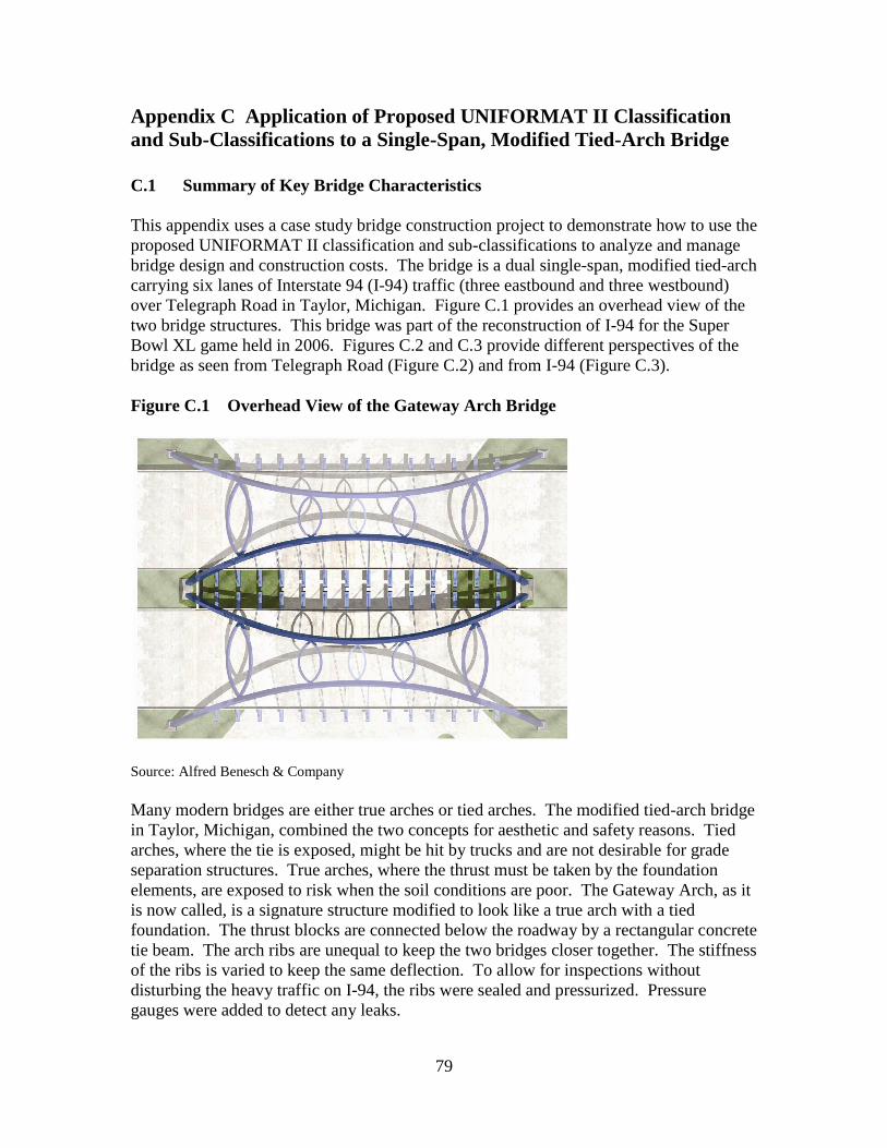
79
Appendix C Application of Proposed UNIFORMAT II Classification
and Sub-Classifications to a Single-Span, Modified Tied-Arch Bridge
C.1 Summary of Key Bridge Characteristics
This appendix uses a case study bridge construction project to demonstrate how to use the
proposed UNIFORMAT II classification and sub-classifications to analyze and manage
bridge design and construction costs. The bridge is a dual single-span, modified tied-arch
carrying six lanes of Interstate 94 (I-94) traffic (three eastbound and three westbound)
over Telegraph Road in Taylor, Michigan. Figure C.1 provides an overhead view of the
two bridge structures. This bridge was part of the reconstruction of I-94 for the Super
Bowl XL game held in 2006. Figures C.2 and C.3 provide different perspectives of the
bridge as seen from Telegraph Road (Figure C.2) and from I-94 (Figure C.3).
Figure C.154Overhead View of the Gateway Arch Bridge
Source: Alfred Benesch & Company
Many modern bridges are either true arches or tied arches. The modified tied-arch bridge
in Taylor, Michigan, combined the two concepts for aesthetic and safety reasons. Tied
arches, where the tie is exposed, might be hit by trucks and are not desirable for grade
separation structures. True arches, where the thrust must be taken by the foundation
elements, are exposed to risk when the soil conditions are poor. The Gateway Arch, as it
is now called, is a signature structure modified to look like a true arch with a tied
foundation. The thrust blocks are connected below the roadway by a rectangular concrete
tie beam. The arch ribs are unequal to keep the two bridges closer together. The stiffness
of the ribs is varied to keep the same deflection. To allow for inspections without
disturbing the heavy traffic on I-94, the ribs were sealed and pressurized. Pressure
gauges were added to detect any leaks.

80
Figure C.255Gateway Arch Bridge as Seen from Telegraph Road
Source: Alfred Benesch & Company
Figure C.356Gateway Arch Bridge as Seen from I-94
Source: Alfred Benesch & Company

81
The project team was challenged with two major criteria: cost and structural integrity.
The team approached the design by analyzing its functions and its worth. The team value
engineered the conventional design of elements and identified the function, cost, and
performance of each element using ASTM Standard Practice E 2013.41
If the function
need/performance is high and cost is low, it has value. If the function need/performance
is low and cost is high, it becomes a mismatch. When mismatches of conventional
design are identified, the team develops innovative solutions to create value of the
elements that has a higher need/performance at a lower cost.
Unique Foundation System
In true arches, the thrust is taken by the foundation supports, such as piles. In tied arches,
the thrust is taken internally by tie beams. There is no redundancy in case of a failure of
the thrust resistance. For this modified tied-arch, the longitudinal arch thrust is resisted
by multiple foundation elements as shown in Figure C.4: the longitudinal foundation ties,
the transverse foundation ties, and battered piles. The concrete foundation ties, buried
beneath Telegraph Road (see the photograph on the right-hand side of Figure C.4), are
sized so that the tensile strength of the concrete is sufficient to carry the arch thrust.
However, should the concrete crack, there is adequate reinforcement in the tie. There are
also 10 cm (4 in) diameter open ducts cast in concrete ties. At present, these are capped
but the tie can be post-tensioned if deemed necessary. In addition, battered piles and
massive earth pressure against the foundation also resist arch thrust.
Figure C.457Gateway Arch Bridge Foundation System
Source: Alfred Benesch & Company
41
ASTM International. “Practice for Constructing FAST Diagrams and Performing Function Analysis
During Value Analysis Study,” E 2013, op cit.
Longitudinal Foundation Tie
Transverse
Foundation
Tie
Longitudinal
Foundation
Tie

82
Arch Ribs
Each structure is a single-span inclined through arch. The interior and exterior arch ribs
are inclined 25 degrees towards each other. The inclination is limited to 25 degrees in
order to maintain the desirable vertical clearance. The ribs are braced together using five
football shaped braces (see Figures C.5 and C.6). The bases of the exterior arch ribs are
located at the Telegraph Road level, while the bases of the interior ribs are located at the
I-94 level. This caused the length of the exterior rib and the interior rib to be different.
The length of the exterior and interior arch ribs are 90.2 m (296 ft) and 78.3 m (257 ft),
respectively. The span length measured between the east and west abutments is 75.0 m
(246 ft).
Figure C.558Longitudinal View of the Arch Ribs
Source: Alfred Benesch & Company
The unequal lengths of the arches posed a challenge to the design team. The arch rib
deflection due to dead and live loads will be different. By carefully varying the stiffness
of the box while maintaining the outside shape and dimension the same, both the
appearance and structural integrity were achieved. The inner thrust block is at the road
level of I-94; the outer thrust block is at the level of Telegraph Road.

83
Figure C.659Transverse View of the Arch Ribs Illustrates Unequal Lengths
Source: Alfred Benesch & Company
The ribs are fixed at each end by the foundation. The arch ribs are a 0.9 m by 1.2 m (3 ft
by 4 ft) box section. The webs of the ribs are 1.91 cm (0.75 in) thick. The flanges for the
exterior ribs and interior ribs are 6.35 cm (2.5 in) thick and 5.72 cm (2.25 in) thick,
respectively.
Maintenance of Arch Ribs
Due to the small size of the arch ribs, future inspection and maintenance of the inside
portion of the box is virtually impossible. Therefore, the arch ribs, arch braces, and the
boxed-sections of transverse beams are pressurized with dry air to prevent moist air from
entering the boxed-sections to cause corrosion. In order to prevent any air leakage from
the pressurized sections, the top flanges of the arch ribs and braces are welded to the
webs using a full penetration weld. The bottom flanges are welded to the webs using a
double side fillet weld. A trapezoidal shape-sealing diaphragm is located inside the arch
box at each hanger location. The portion inside the sealing diaphragm is not pressurized,
and an access opening in the web is provided to facilitate inspection of the unsealed
portion of the arch.
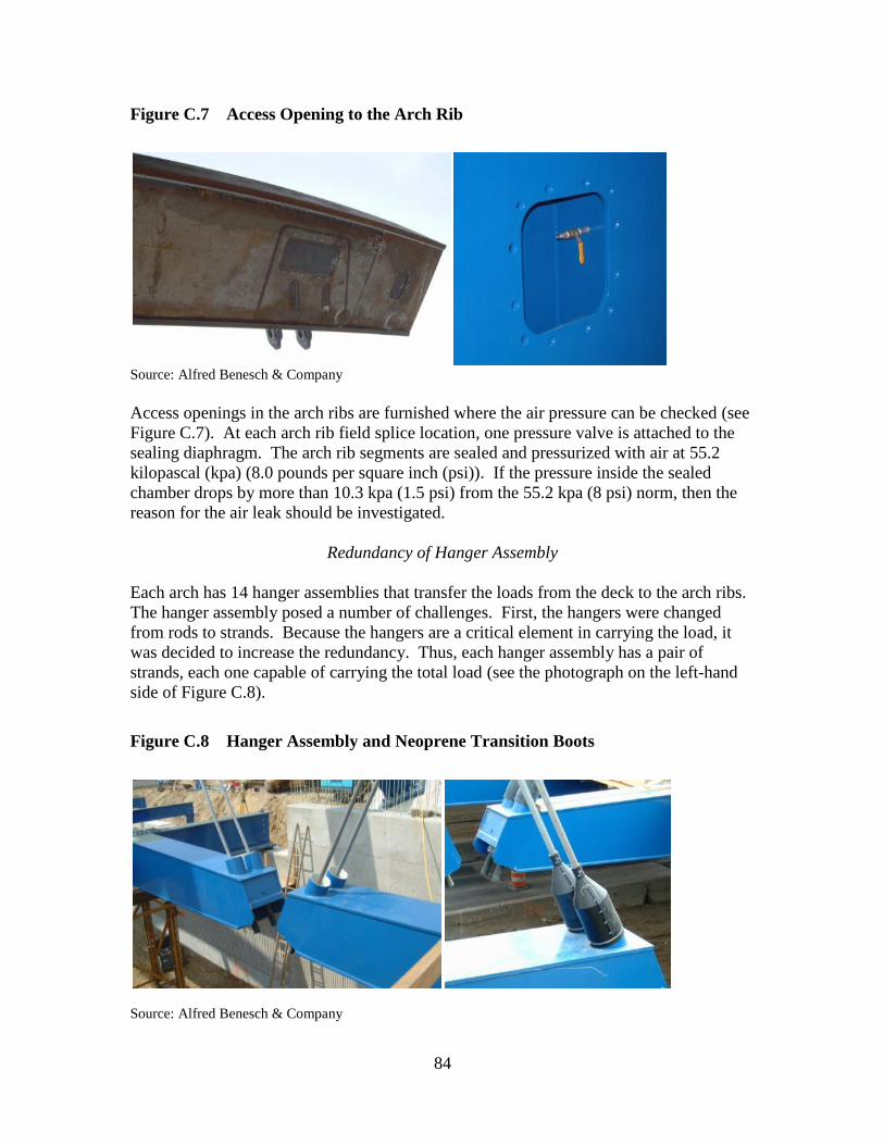
84
Figure C.760Access Opening to the Arch Rib
Source: Alfred Benesch & Company
Access openings in the arch ribs are furnished where the air pressure can be checked (see
Figure C.7). At each arch rib field splice location, one pressure valve is attached to the
sealing diaphragm. The arch rib segments are sealed and pressurized with air at 55.2
kilopascal (kpa) (8.0 pounds per square inch (psi)). If the pressure inside the sealed
chamber drops by more than 10.3 kpa (1.5 psi) from the 55.2 kpa (8 psi) norm, then the
reason for the air leak should be investigated.
Redundancy of Hanger Assembly
Each arch has 14 hanger assemblies that transfer the loads from the deck to the arch ribs.
The hanger assembly posed a number of challenges. First, the hangers were changed
from rods to strands. Because the hangers are a critical element in carrying the load, it
was decided to increase the redundancy. Thus, each hanger assembly has a pair of
strands, each one capable of carrying the total load (see the photograph on the left-hand
side of Figure C.8).
Figure C.861Hanger Assembly and Neoprene Transition Boots
Source: Alfred Benesch & Company

85
Each hanger assembly consists of two 5.4 cm (2.125 in) diameter, ASTM A586 structural
stands, spaced 38.1 cm (15 in) center to center. The inner wires of each strand are
galvanized with Class A coating, while the outer wires are galvanized with Class C
coating. Each strand is attached to the arch ribs using a 4.45 cm (1.75 in) thick hanger
support plate and ASTM A148 Grade 105/85 galvanized open type socket.
Neoprene transition boots, secured to 25.4 cm (10 in) diameter standard pipe, welded to
the transverse beams and to the strands using stainless steel clamps, are used to prevent
moisture from entering inside the connections between the transverse beams and the
strands and to enhance aesthetics (see the photograph on the right-hand side of Figure
C.8). A hanger separator is installed between the two strands of each hanger assembly
for the middle ten hangers. Hanger separators increase in-plane stiffness of the strands
by constraining the relative motions between them and increasing the stiffness of the
hanger against transverse winds.
The bridge was designed to facilitate the replacement of individual strands. Each strand
of the pair is capable of supporting the deck and the full live load while the other is
replaced.
C.2 Cost Accounting Framework
The costs of each element are organized around the proposed UNIFORMAT II
classification of bridge elements, as described in Table 2.3. Because these costs have
associated with them project management functions and risk management functions, two
additional tables are needed. Table C.1 covers program management-related costs and
Table C.2 covers risk management-related costs. Each table is organized as a three-level
hierarchy.
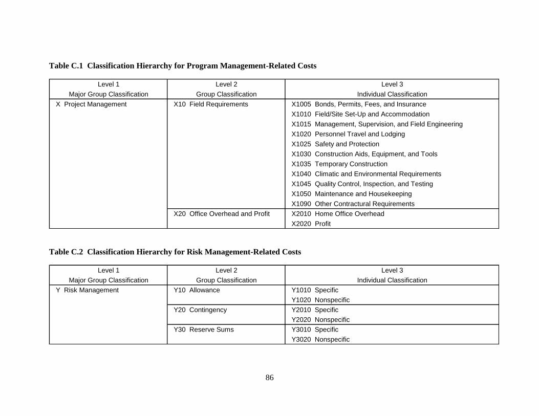
86
Table C.1 Classification Hierarchy for Program Management-Related Costs
Level 1 Level 2 Level 3
Major Group Classification Group Classification Individual Classification
X Project Management X10 Field Requirements X1005 Bonds, Permits, Fees, and Insurance
X1010 Field/Site Set-Up and Accommodation
X1015 Management, Supervision, and Field Engineering
X1020 Personnel Travel and Lodging
X1025 Safety and Protection
X1030 Construction Aids, Equipment, and Tools
X1035 Temporary Construction
X1040 Climatic and Environmental Requirements
X1045 Quality Control, Inspection, and Testing
X1050 Maintenance and Housekeeping
X1090 Other Contractural Requirements
X20 Office Overhead and Profit X2010 Home Office Overhead
X2020 Profit
Table C.2 Classification Hierarchy for Risk Management-Related Costs
Level 1 Level 2 Level 3
Major Group Classification Group Classification Individual Classification
Y Risk Management Y10 Allowance Y1010 Specific
Y1020 Nonspecific
Y20 Contingency Y2010 Specific
Y2020 Nonspecific
Y30 Reserve Sums Y3010 Specific
Y3020 Nonspecific

87
The prefix in Table C.1 is X indicating its relationship to Table 1 in ASTM E 2083,
Standard Classification for Building Construction Field Requirements and Office
Overhead and Profit. Level 1 in the hierarchy contains the single entry X Project
Management. Level 2 in the hierarchy contains two entries: X10 Field Requirements and
X20 Office Overhead and Profit. Level 3 entries under X10 Field Requirements include
such cost items as X1030 Construction Aids, Equipment, and Tools (e.g., cranes and
scaffolding) and X1035 Temporary Construction (e.g., coffer dams).
The Prefix in Table C.2 is Y indicating its relationship to ASTM E 2168, Standard
Classification for Allowance, Contingency, and Reserve Sums in Building Construction
Estimating. Due to the unique characteristics of the Gateway Arch Bridge, ASTM
E 2168 was of particular importance. Level 1 in the hierarchy contains the single entry Y
Risk Management. Level 2 in the hierarchy contains three entries: Y10 Allowance, Y20
Contingency, and Y30 Reserve Sums. The two Level 3 entries under Y10 Allowance
are: Y1010 Specific and Y1020 Nonspecific. There are similar breakdowns for Y20
Contingency and Y30 Reserve Sums. For example, under Y20 Contingency, Y2010
Specific covers planning contingency, design contingency, and construction contingency,
whereas Y2020 Nonspecific covers overall unexpected events or items. As the project
progresses, some of the planning and design contingencies will be moved into the base
cost. Construction contingency will remain until the construction is complete.
In addition to the three risk management terms—allowance, contingency, and reserve
sums—included in ASTM E 2168, it is useful to introduce a fourth term, base cost. Base
cost includes all costs for the construction work including all trade costs and the prime
contractor’s field requirements and office overhead and profit reported in Table C.1. It is
instructive to review the relationship between these four cost terms. Understanding these
relationships is at the heart of analyzing and managing design and construction costs for
complex projects such as the Gateway Arch Bridge. Base cost plus allowance is
designated as the minimum cost. Base cost plus allowance and contingency is designated
as the expected cost. Base cost plus allowance, contingency, and reserve sums is
designated as the maximum cost.
C.3 Cost Analysis of the Gateway Arch Bridge Using the Proposed
UNIFORMAT II Elemental Classification and Sub-Classifications
The total cost for one of the two bridge structures making up the Gateway Arch Bridge is
$6.76 million. Since the two bridge structures are identical, their total costs are the same.
The cost analysis of the Gateway Arch Bridge using the proposed UNIFORMAT II
elemental classification and sub-classifications is presented in Table C.3 and summarized
in Figure C.9. Table C.3 records information for each of the five levels in the proposed
UNIFORMAT II bridge classification. Table C.3 includes alphanumeric designations
and element/sub-element names, dollar values, percent of total cost associated with those
dollar values, and unit costs. Figure C.9 records the cost distribution of selected Group
Elements and Individual Elements. The costs summarized in Figure C.9 are the major
Substructure and Superstructure Group Elements and Individual Elements; they account
for approximately 85 % of the Gateway Arch Bridge’s total cost.
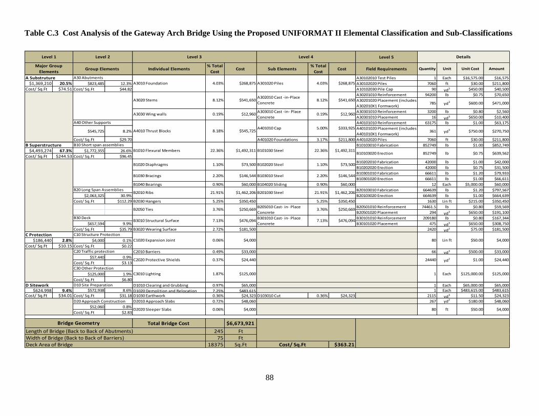
88
Table C.3 Cost Analysis of the Gateway Arch Bridge Using the Proposed UNIFORMAT II Elemental Classification and Sub-Classifications
Level 5
A30102010 Test Piles 1 Each $16,575.00 $16,575
$1,369,210 20.5% $823,485 12.3% A30102020 Piles 7060 ft $30.00 $211,800
Cost/ Sq.Ft $74.51 Cost/ Sq.Ft $44.82 A10102030 Pile Cap 90 yd3 $450.00 $40,500
A30201010 Reinforcement 94200 lb $0.75 $70,650
A30201020 Placement (includes
A302010X1 Formwork)785 yd3 $600.00 $471,000
A30301010 Reinforcement 3200 lb $0.80 $2,560
A30301010 Placement 16 yd3 $650.00 $10,400
A40101010 Reinforcement 63175 lb $1.00 $63,175
$545,725 8.2%A40101020 Placement (includes
A401010X1 Formwork)361 yd3 $750.00 $270,750
Cost/ Sq.Ft $29.70 A401020 Foundations 3.17% $211,800 A40102020 Piles 7060 ft $30.00 $211,800
B10103010 Fabrication 852749 lb $1.00 $852,749
$4,493,274 67.3% $1,772,355 26.6%
Cost/ Sq.Ft $244.53 Cost/ Sq.Ft $96.45
B10202010 Fabrication 42000 lb $1.00 $42,000
B10202020 Erection 42000 lb $0.75 $31,500
B10301010 Fabrication 66611 lb $1.20 $79,933
B10301020 Erection 66611 lb $1.00 $66,611
B1040 Bearings 0.90% $60,000 B104020 Sliding 0.90% $60,000 12 Each $5,000.00 $60,000
B20103010 Fabrication 664639 lb $1.20 $797,567
$2,063,325 30.9% B20103020 Erection 664639 lb $1.00 $664,639
Cost/ Sq.Ft $112.29 B2030 Hangers 5.25% $350,450 5.25% $350,450 1630 Lin ft $215.00 $350,450
B20501010 Reinforcement 74461.5 lb $0.80 $59,569
B20501020 Placement 294 yd3 $650.00 $191,100
B30101010 Reinforcement 209180 lb $0.80 $167,344
$657,594 9.9% B30101020 Placement 475 yd3 $650.00 $308,750
Cost/ Sq.Ft $35.79 B3020 Wearing Surface 2.72% $181,500 2420 yd2 $75.00 $181,500
$186,440 2.8% $4,000 0.1%
Cost/ Sq.Ft $10.15 Cost/ Sq.Ft $0.22
C2010 Barriers 0.49% $33,000 66 yd3 $500.00 $33,000
$57,440 0.9%
Cost/ Sq.Ft $3.13
$125,000 1.9%
Cost/ Sq.Ft $6.80
D1010 Clearing and Grubbing 0.97% $65,000 1 Each $65,000.00 $65,000
$624,998 9.4% $572,938 8.6% D1020 Demolition and Relocation 7.25% $483,615 1 Each $483,615.00 $483,615
Cost/ Sq.Ft $34.01 Cost/ Sq.Ft $31.18 D1030 Earthwork 0.36% $24,323 D103010 Cut 0.36% $24,323 2115 yd3 $11.50 $24,323
D20 Approach Construction D2010 Approach Slabs 0.72% $48,060 267 yd2 $180.00 $48,060
$52,060 0.8%
Cost/ Sq.Ft $2.83
Total Bridge Cost $6,673,921
245 Ft
75 Ft
18375 Sq.Ft $363.21
lb
C1020 Expansion Joint 0.06% $4,000 80 Lin ft $50.00
B3010 Structural Surface
852749
$4,000
Deck Area of Bridge
B20 Long Span AssembliesB2010 Ribs B201030 Steel 21.91% $1,462,206
B2050 TiesB205010 Cast- in- Place
Concrete3.76% $250,669
21.91% $1,462,206
3.76% $250,669
C20 Traffic protection
C2020 Protective Shields
Cost/ Sq.Ft
Length of Bridge (Back to Back of Abutments)
Width of Bridge (Back to Back of Barriers)
B30 Deck
Level 1 Level 2
Major Group
ElementsGroup Elements Individual Elements Sub Elements
B301010 Cast- in- Place
Concrete7.13% $476,094
$73,500
2.20% $146,544
B1010 Flexural Members B101030 Steel
A3030 Wing wallsA303010 Cast -in- Place
Concrete0.19% $12,960
A Substruture A30 Abutments
A3010 Foundation
C Protection C10 Structure Protection
B Superstructure B10 Short span assemblies
A3020 Stems
$0.75 $639,562
A40 Other Supports
A4010 Thrust BlocksA401010 Cap 5.00% $333,925
B1020 Diaphragms B102020 Steel 1.10% $73,500
B1030 Bracings B103010 Steel 2.20% $146,544
$1,492,311
1.10%
Bridge Geometry
Field Requirements Quantity
Level 4
Cost % Total
Cost
Level 3
% Total
Cost Cost
$125,000
D Sitework D10 Site Preparation
D2020 Sleeper Slabs
Unit Unit Cost Amount
Details
C30 Other Protection
C3010 Lighting
0.06% $4,000 80 ft $4,000
$24,440
1.87% $125,000 1 Each $125,000.00
yd2 $1.000.37% $24,440 24440
$50.00
4.03% $268,875
8.12% $541,650
0.19% $12,960
22.36% $1,492,311
8.18% $545,725
22.36%
A301020 Piles 4.03% $268,875
7.13% $476,094
A302010 Cast -in-Place
Concrete8.12% $541,650
B10103020 Erection

89
Figure C.962Cost Distribution of Selected Group Elements and Individual Elements for the Gateway Arch Bridge
Source: Alfred Benesch & Company
90
Table C.3 is organized so that the costs from each lower level in the UNIFORMAT II
hierarchy can be easily aggregated. The first four columns correspond to Levels 1, 2, 3,
and 4 of the proposed UNIFORMAT II elemental classification. The last five columns
list any Level 5 Sub Elements, as well as item alphanumeric designation and name,
quantities, units of measure, unit costs, and item cost. Two intermediate columns
summarize the cost characteristics of each Level 4 Sub Element. In several cases—
B3020 Wearing Surface—the entries correspond to the Level 3 Individual element. The
two intermediate columns show the cost of the Level 4 Sub Element, which is obtained
by summing over all Level 5 Sub Elements associated with that Level 4 Sub Element,
and the per cent of total cost associated with that cost. For example, the Level 4 Sub
Element, A301020 Piles, has a cost of $269 000. Given that the total cost of the bridge is
$6.76 million, this value represents 4.03 % of the total cost.
The cost of a Level 3 Individual Element is obtained by summing over all of its Level 4
Sub Elements. In a similar fashion, the cost of a Level 2 Group Element is obtained by
summing over all of its Level 3 Individual Elements and the cost of a Level 1 Major
Group Element is obtained by summing over all of its Level 2 Group Elements. The cost
for each Major Group Element and Group Element, along with its per cent of total cost
and unit cost, are recorded in the first two columns of Table C.3. Note that some Group
Elements have a single Level 3 Individual Element. For example, Group Element A40,
Other Supports, has a single Individual Element, A4010 Thrust Blocks. In such cases the
values recorded under the Level 2 Group Element heading correspond to those associated
with the Level 3 Individual Element.
The values recorded in Table C.3 provide the basis for Figure C.9. Figure C.9 presents a
cost distribution of selected Group Elements and Individual Elements tied to a graphical
representation of a longitudinal view of the Gateway Arch Bridge. The figure includes
the alphanumeric string, the name of the Group Element or Individual Element, its cost,
and its per cent of total cost. Two Group Elements and six Individual Elements are
highlighted in Figure C.9. Reference to Figure C.9 reveals that the Level 2 Group
Element A30 Abutment has a cost of $824 000, which corresponds to 12.3 % of the total
cost. The other Level 2 Group Element shown in Figure C.9, B30 Deck, has a cost of
$658 000 or 9.9 % of total cost. Two Individual Elements, B1010 Flexural Members and
B2010 Ribs, are of particular importance, since they each represent more than 20 % of
the total cost of the bridge. Table C.3 and Figure C.9 illustrate how the proposed
UNIFORMAT II elemental classification can be used to focus attention on those
elements that drive the overall costs of a bridge project, as well as those elements that are
associated with special characteristics—in this case the unique foundation system—of a
particular bridge.
The Gateway Arch Bridge won six awards, including two national awards. The two
national awards were the 2006 Outstanding Project Award from the National Council of
structural Engineers Association and the 2007 Prize Bridge—Medium Span Award from
the National Steel Bridge Alliance. In addition to the two national awards, the Gateway
Arch Bridge won the 2006 Best Medium Structure Award from the Structural Engineers
Association of Illinois; the 2006 Engineering Honorable Conceptor Award from the
91
Michigan Chapter of the American Council of Engineering Companies; the 2008
Partnering Award from the Michigan Construction Quality Partnership; and the 2008
Making a Difference Gold Award for Partnering from the National Partnership for
Highway Quality. A major criterion for its selection as an award recipient was its cost
effectiveness.


