Ó 2012 Wiley-VCH Verlag GmbH & Co. KGaA, Weinheim Nitric Acid, Nitrous Acid, and Nitrogen Oxides MICHAEL THIEMANN, Uhde GmbH, Dortmund, Federal Republic of Germany ERICH SCHEIBLER, Uhde GmbH, Dortmund, Federal Republic of Germany KARL WILHELM WIEGAND, Uhde GmbH, Dortmund, Federal Republic of Germany 1. Nitric Acid ....................... 177 1.1. Introduction...................... 177 1.2. Properties ....................... 178 1.3. Industrial Production............... 179 1.3.1. Oxidation of Ammonia .............. 180 1.3.2. Oxidation and Absorption of Nitrogen Oxides .......................... 184 1.3.3. Equipment........................ 191 1.3.3.1. Filters and Mixers .................. 191 1.3.3.2. Burners and Waste-Heat Boilers ........ 192 1.3.3.3. Compressors and Turbines ............ 193 1.3.3.4. Heat Exchangers and Columns ......... 195 1.3.3.5. Construction Materials ............... 198 1.3.4. Processes ........................ 200 1.3.4.1. Weak Acid Processes................ 200 1.3.4.2. Concentrated Acid Processes .......... 206 1.4. Environmental Protection ........... 211 1.4.1. Wastewater ....................... 211 1.4.2. Stack Gas ........................ 211 1.4.2.1. Emission Limits ................... 211 1.4.2.2. Analysis ......................... 212 1.4.2.3. Control of NO x Emissions ............ 212 1.5. Storage and Transportation .......... 216 1.6. Uses and Economic Aspects .......... 216 2. Nitrous Acid ..................... 217 3. Nitrogen Oxides ................... 218 3.1. Dinitrogen Monoxide ............... 218 3.2. Nitrogen Monoxide ................ 219 3.3. Nitrogen Dioxide and Dinitrogen Tetroxide ........................ 220 3.4. Dinitrogen Trioxide ................ 221 3.5. Dinitrogen Pentoxide ............... 222 4. Toxicology and Occupational Health ... 222 References ....................... 223 1. Nitric Acid 1.1. Introduction Nitric acid is a strong acid that occurs in nature only in the form of nitrate salts. When large-scale production of nitric acid began, sodium nitrate (soda saltpeter, Chile saltpeter) was used as the feedstock. At the beginning of the 20th century the reserves of Chile saltpeter were thought to be nearing exhaustion, so processes were developed for replacing nitrogen from natural nitrates with atmospheric nitrogen. Three techniques were used industrially: 1. Production of nitrogen monoxide by reacting atmospheric nitrogen and oxygen at > 2000 C (direct processes) 2. Production of ammonia by hydrolysis of calcium cyanamide under pressure 3. Production of ammonia from nitrogen and hydrogen The direct combustion of air in an electric arc, developed by BIRKELAND and EYDE, was aban- doned because of its poor energy efficiency. Later direct processes, such as thermal nitrogen monoxide synthesis with fossil fuels or nitrogen monoxide synthesis in nuclear reactors, did not gain widespread acceptance. Ammonia produc- tion from calcium cyanamide was of only transi- tory value. Ammonia produced from nitrogen and hydrogen by the Haber – Bosch process (! Ammonia, 2. Production Processes) is, however, still used as feedstock for nitric acid production. The crucial step in nitric acid production, the catalytic combustion of ammonia, was developed by OSTWALD around the turn of the century. The most important design parameters for a nitric acid plant were determined first in laboratory tests and later in a pilot plant. The first production facility employing the Ostwald process came on stream in 1906 at Gerthe in Germany [1–3]. DOI: 10.1002/14356007.a17_293
Transcript
� 2012 Wiley-VCH Verlag GmbH & Co. KGaA, Weinheim
Article No : a17_293
Nitric Acid, Nitrous Acid, and Nitrogen Oxides
MICHAEL THIEMANN, Uhde GmbH, Dortmund, Federal Republic of Germany
ERICH SCHEIBLER, Uhde GmbH, Dortmund, Federal Republic of Germany
KARL WILHELM WIEGAND, Uhde GmbH, Dortmund, Federal Republic of Germany
Nitric acid is a strong acid that occurs in natureonly in the form of nitrate salts.When large-scaleproduction of nitric acid began, sodium nitrate(soda saltpeter, Chile saltpeter) was used as thefeedstock. At the beginning of the 20th centurythe reserves of Chile saltpeter were thought to benearing exhaustion, so processes were developedfor replacing nitrogen from natural nitrateswith atmospheric nitrogen. Three techniqueswere used industrially:
1. Production of nitrogen monoxide by reactingatmospheric nitrogen and oxygen at > 2000�C (direct processes)
2. Production of ammonia by hydrolysis ofcalcium cyanamide under pressure
3. Production of ammonia from nitrogen andhydrogen
The direct combustion of air in an electric arc,developed by BIRKELAND and EYDE, was aban-doned because of its poor energy efficiency.Later direct processes, such as thermal nitrogenmonoxide synthesis with fossil fuels or nitrogenmonoxide synthesis in nuclear reactors, did notgain widespread acceptance. Ammonia produc-tion from calcium cyanamide was of only transi-tory value. Ammonia produced from nitrogenand hydrogen by the Haber – Bosch process(! Ammonia, 2. Production Processes) is,however, still used as feedstock for nitric acidproduction.
The crucial step in nitric acid production,the catalytic combustion of ammonia, wasdeveloped by OSTWALD around the turn of thecentury. The most important design parametersfor a nitric acid plant were determined first inlaboratory tests and later in a pilot plant. Thefirst production facility employing the Ostwaldprocess came on stream in 1906 at Gerthe inGermany [1–3].
DOI: 10.1002/14356007.a17_293
Most of the nitric acid produced is used toform inorganic fertilizers (! Phosphate Fertili-zers); it is mostly neutralized with ammonia toform ammonium nitrate (! Ammonium Com-pounds, Section 1.2.1.).
1.2. Properties
Nitric acid was known to the ancient Egyptiansbecause of its special ability to separate goldand silver. Many well-known alchemists in theMiddle Ages experimented with the acid. In themiddle of the 17th century, GLAUBER reported itspreparation from saltpeter and sulfuric acid.
Physical Properties. Nitric acid [7697-37-2], Mr 63.013, is miscible with water in allproportions. At a concentration of 69.2 wt%, itforms a maximum-boiling azeotrope with water.The azeotropic mixture boils at 121.8 �C. Pureanhydrous nitric acid boils at 83 – 87 �C; thereason a range of boiling points are cited inthe literature is that the acid decomposes onheating [4]:
4 HNO3!2 H2Oþ4 NO2þO2
The nitrogen dioxide formed on decomposi-tion colors the acid yellow or even red at higherconcentrations. Because the vapors can alsoabsorb moisture, the term ‘‘red fuming nitricacid’’ is used. In the pure anhydrous state, nitricacid is a colorless liquid.
The most important physical properties ofpure nitric acid follow:
fp �41.59 �Cbp 82.6 � 0.2 �CDensity, liquid
at 0 �C 1549.2 kg/m3
at 20 �C 1512.8 kg/m3
at 40 �C 1476.4 kg/m3
Refractive index n24D 1.3970
Dynamic viscosity
at 0 �C 1.092 mPa � sat 25 �C 0.746 mPa � sat 40 �C 0.617 mPa � s
Surface tension
at 0 �C 0.04356 N/m
at 20 �C 0.04115 N/m
at 40 �C 0.03776 N/m
Thermal conductivity (20 �C) 0.343 W m�1 K�1
Standard enthalpy of formation
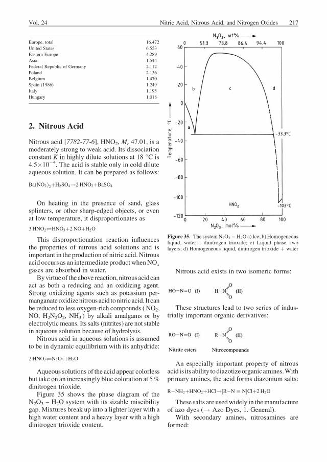
Liquid 2.7474 J/g
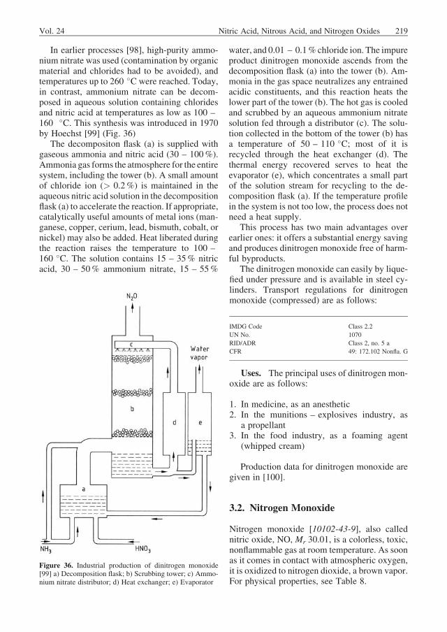
Gas 2.1258 J/g
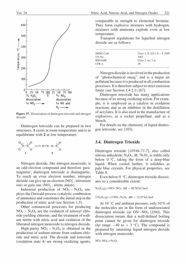
Heat of vaporization (20 �C) 626.3 J/g
Specific heat
at 0 �C 1.7601 J g�1 K�1
at 20 �C 1.7481 J g�1 K�1
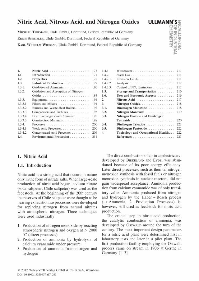
The decomposition of nitric acid makes itsphysical properties difficult to determine at high-er temperature. Up to ca. 50 �C, conventionalmethods of measurement are possible; beyondthis, indirect thermodynamic calculations orspecial short-time measuring methods must beemployed. Figure 1 illustrates the vapor pressurecurve of pure nitric acid. Table 1 lists importantphysical properties of aqueous nitric acid. Acomprehensive review of the physical and chem-ical properties of nitric acid is given in [6].
Chemical Properties. Concentrated nitricacid, with nitrogen in the þ 5 oxidation state,acts as a strong oxidizing agent. The reaction
NO�3 þ4 Hþ�NOþ2 H2O
goes to the right for all substances with oxidationpotentials more negative than þ 0.93 V [7]. Forexample, copper (þ 0.337 V) and silver(þ 0.799 V) are dissolved by nitric acid, where-as gold (þ 1.498 V) and platinum (þ 1.2 V) areresistant. In practice, 50% nitric acid (aqua
Figure 1. Vapor pressure curve for pure nitric acid
178 Nitric Acid, Nitrous Acid, and Nitrogen Oxides Vol. 24
fortis) is used for separating gold from silver.Some base metals, such as aluminum and chro-mium, are attacked by nitric acid only at theirsurfaces because a thin oxide layer is formed,which protects (i.e., passivates) the core againstfurther oxidation. As a result of this passivation,alloyed steel equipment can be used in nitric acidtechnology.
Highly diluted nitric acid is almost completelydissociated
HNO3þH2O�H3OþþNO�
3
and does not attack copper and more noblemetals. Due to its acid nature, however, it reactswith base metals, liberating hydrogen and form-ing nitrates.
A mixture (volume ratio 3 : 1) of concentratednitric acid and concentrated hydrochloric acid(aqua regia) also dissolves gold.
1.3. Industrial Production
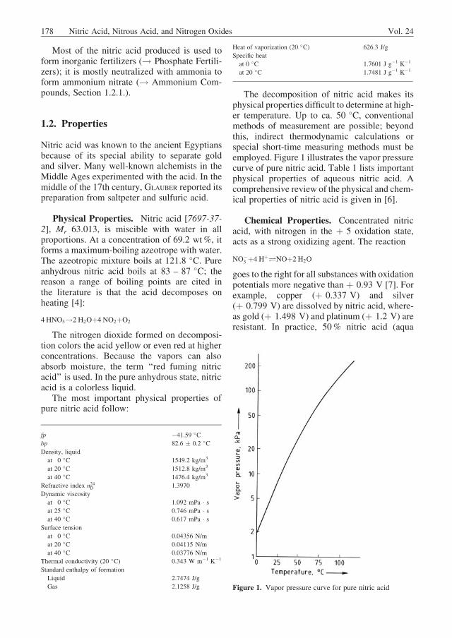
The industrial production of nitric acid by theOstwald process is described in this section. Theprocess involves three chemical steps (Fig. 2):
1. Catalytic oxidation of ammonia with atmo-spheric oxygen to yield nitrogen monoxide:
4 NH3þ5 O2!4 NOþ6 H2O ð1ÞOxidation of the nitrogen monoxide productto nitrogen dioxide or dinitrogen tetroxide:
2 NOþO2!2 NO2�N2O4 ð2Þ
2. Absorption of the nitrogen oxides to yieldnitric acid:
3 NO2þH2O!2 HNO3þNO ð3Þ
The way in which these three steps areimplemented characterizes the various nitric acidprocesses. In monopressure (single-pressure)processes, ammonia combustion and NOx ab-sorption take place at the sameworking pressure.These include medium-pressure (230 –600 kPa) and high-pressure (700 – 1100 kPa)processes. Very few plants currently employ lowpressure (100 – 220 kPa) for both combustionand absorption.
In dual-pressure (split-pressure) processes,the absorption pressure is higher than the com-bustion pressure. Modern dual-pressure plantsfeature combustion at 400 – 600 kPa and ab-sorption at 900 – 1400 kPa. Some older plantsstill employ atmospheric combustion and medi-um-pressure absorption.
Table 1. Physical properties of aqueous nitric acid as a function of
composition [5]
HNO3
concentration,
wt %
Density
(20 �C),g/cm3
mp, �C bp, �C Partial
pressure
(20 �C), kPa
HNO3 H2O
0 0.99823 0 100.0 2.23
10 1.0543 �7 101.2 2.26
20 1.1150 �17 103.4 2.02
30 1.1800 �36 107.0 1.76
40 1.2463 �30 112.0 1.44
50 1.3100 �20 116.4 0.03 1.05
60 1.3667 �22 120.4 0.12 0.65
70 1.4134 �41 121.6 0.39 0.35
80 1.4521 �39 116.6 1.4 0.12
90 1.4826 �60 102.0 3.6 0.03
100 1.5129 �42 86.0 6.0 0
Figure 2. Ostwald process
Vol. 24 Nitric Acid, Nitrous Acid, and Nitrogen Oxides 179
Intensive work on ammonia combustion aswell as the oxidation and absorption of nitrogenoxides has been well documented since the early1920s. Up to now the combustion of ammoniahas been considered as a heterogeneous catalyticsurface reaction with undesirable side reactions.The oxidation of nitrogen monoxide is a rareexample of a homogeneous third-order gas-phasereaction. The absorption of NOx is a heteroge-neous reaction between fluid (i.e., gas and liquid)phases.
1.3.1. Oxidation of Ammonia
The oxidation of ammonia to nitrogen monoxideis described by the equation
4 NH3þ5 O2!4 NOþ6 H2O DH ¼ �904kJ=mol ð4Þ
Over a suitable catalyst, 93 – 98% of the feedammonia is converted to nitrogenmonoxide. Theremainder participates in undesirable side reac-tions leading to dinitrogen monoxide (nitrousoxide, laughing gas)
4 NH3þ4 O2!2 N2Oþ6 H2O DH ¼ �1105 kJ=mol ð5Þ
and to nitrogen
4 NH3þ3 O2!2 N2þ6 H2O DH ¼ �1268 kJ=mol ð6Þ
Other undesirable reactions are the decompo-sition of the nitrogen monoxide product
2 NO!N2þO2 DH ¼ �90 kJ=mol ð7Þand its reaction with ammonia
4 NH3þ6 NO!5 N2þ6 H2O DH ¼ �1808 kJ=mol ð8Þ
Reaction Mechanism. Early theories of themechanism for the oxidation of ammonia dif-fered as to which intermediate product wasformed. The classical theories were proposed byANDRUSSOV (nitroxyl theory, 1926), RASCHIG
(imide theory, 1927), and BODENSTEIN (hydroxyl-amine theory, 1935) [3].According to thehydrox-ylamine theory, ammonia reacts with atomicoxygen adsorbed on the catalyst to yield hydrox-ylamine. This in turn reacts with molecularoxygen to form nitrous acid, which then dissoci-ates to nitrogen monoxide and hydroxyl ions:
O2 � 2 Oðadsorb:Þ
O ðadsorb:ÞþNH3!NH2OH
NH2OHþO2!HNO2þH2O
HNO2!NOþOH�
2 OH�!H2OþO
In oxidation experiments under high vacuum,BODENSTEIN and coworkers detected both hydrox-ylamine and nitrous acid as intermediate pro-ducts on the platinum catalyst. Later studies witha mass spectrometer showed that no such inter-mediate products are found above 400 �C [8]. Inthese tests, both molecular and atomic oxygenwas found on the catalyst surface. A direct reac-tion between oxygen and ammonia was thereforepostulated according to the following equations:
NH3þO2!NOþH2OþH
NH3þO!NOþH2þH
In fast reactions such as the combustion ofammonia (the reaction time for Eq. 4 is ca.10�11 s), however, the possible intermediatesmost likely cannot be detected because they arevery short-lived and present in very low concen-trations. NOWAK [9] has compared the numeroustheories of ammonia combustion. PIGNET andSCHMIDT present a classical Langmuir – Hinshel-wood treatment of the process [10]. The possi-bility that the combustion of ammonia may beconsidered as a homogeneous catalytic reactionis now being discussed.
At low temperature (200 – 400 �C), the rateof ammonia oxidation is limited by the reactionkinetics. The byproducts nitrogen, and especiallydinitrogen monoxide, are formed preferentially.Between 400 and 600 �C, the reaction ratebecomes limited by mass transfer, which isthen dominant above 600 �C. Control by masstransfer relates to the diffusion rate of ammoniathrough the gas film to the catalyst surface. Theproduct in this reaction regime is nitrogenmonoxide.
The catalyst surface experiences a very lowpartial pressure of ammonia and a diminishedpartial pressure of oxygen due to mass-transferlimitations. The catalytic side reaction between
180 Nitric Acid, Nitrous Acid, and Nitrogen Oxides Vol. 24
ammonia and nitrogen monoxide is acceleratedby an increase in the partial pressures of bothspecies on the catalyst surface. If catalystpoisoning occurs,the number of active centersdecreases and the partial pressure, particularlythat of ammonia, increases at the remainingactive centers. The result is increased formationof undesirable byproducts. In practice, this shiftis offset by raising the temperature, i.e., thereaction is again displaced into the region limitedby gas-film diffusion.
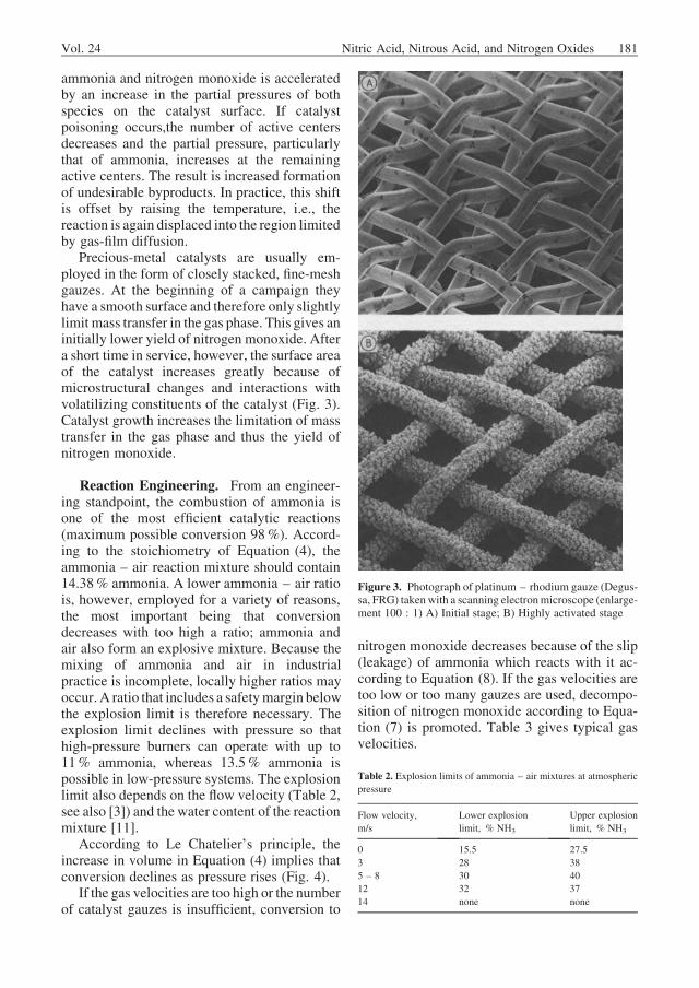
Precious-metal catalysts are usually em-ployed in the form of closely stacked, fine-meshgauzes. At the beginning of a campaign theyhave a smooth surface and therefore only slightlylimit mass transfer in the gas phase. This gives aninitially lower yield of nitrogen monoxide. Aftera short time in service, however, the surface areaof the catalyst increases greatly because ofmicrostructural changes and interactions withvolatilizing constituents of the catalyst (Fig. 3).Catalyst growth increases the limitation of masstransfer in the gas phase and thus the yield ofnitrogen monoxide.
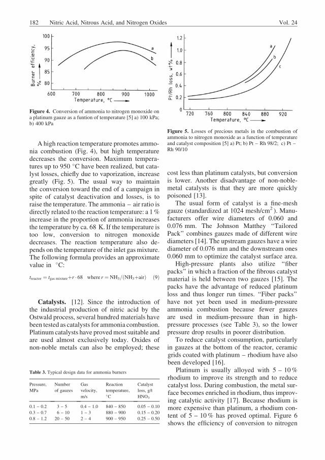
Reaction Engineering. From an engineer-ing standpoint, the combustion of ammonia isone of the most efficient catalytic reactions(maximum possible conversion 98%). Accord-ing to the stoichiometry of Equation (4), theammonia – air reaction mixture should contain14.38% ammonia. A lower ammonia – air ratiois, however, employed for a variety of reasons,the most important being that conversiondecreases with too high a ratio; ammonia andair also form an explosive mixture. Because themixing of ammonia and air in industrialpractice is incomplete, locally higher ratios mayoccur. A ratio that includes a safetymargin belowthe explosion limit is therefore necessary. Theexplosion limit declines with pressure so thathigh-pressure burners can operate with up to11% ammonia, whereas 13.5% ammonia ispossible in low-pressure systems. The explosionlimit also depends on the flow velocity (Table 2,see also [3]) and the water content of the reactionmixture [11].
According to Le Chatelier’s principle, theincrease in volume in Equation (4) implies thatconversion declines as pressure rises (Fig. 4).
If the gas velocities are too high or the numberof catalyst gauzes is insufficient, conversion to
nitrogen monoxide decreases because of the slip(leakage) of ammonia which reacts with it ac-cording to Equation (8). If the gas velocities aretoo low or too many gauzes are used, decompo-sition of nitrogen monoxide according to Equa-tion (7) is promoted. Table 3 gives typical gasvelocities.
Table 2. Explosion limits of ammonia – air mixtures at atmospheric
pressure
Flow velocity, Lower explosion Upper explosion
m/s limit, % NH3 limit, % NH3
0 15.5 27.5
3 28 38
5 – 8 30 40
12 32 37
14 none none
Figure 3. Photograph of platinum – rhodium gauze (Degus-sa, FRG) takenwith a scanning electronmicroscope (enlarge-ment 100 : 1) A) Initial stage; B) Highly activated stage
Vol. 24 Nitric Acid, Nitrous Acid, and Nitrogen Oxides 181
A high reaction temperature promotes ammo-nia combustion (Fig. 4), but high temperaturedecreases the conversion. Maximum tempera-tures up to 950 �C have been realized, but cata-lyst losses, chiefly due to vaporization, increasegreatly (Fig. 5). The usual way to maintainthe conversion toward the end of a campaign inspite of catalyst deactivation and losses, is toraise the temperature. The ammonia – air ratio isdirectly related to the reaction temperature: a 1%increase in the proportion of ammonia increasesthe temperature by ca. 68 K. If the temperature istoo low, conversion to nitrogen monoxidedecreases. The reaction temperature also de-pends on the temperature of the inlet gasmixture.The following formula provides an approximatevalue in �C:
treactor ¼ tgas mixtureþr � 68 where r ¼ NH3=ðNH3þairÞ ð9Þ
Catalysts. [12]. Since the introduction ofthe industrial production of nitric acid by theOstwald process, several hundred materials havebeen tested as catalysts for ammonia combustion.Platinum catalysts have provedmost suitable andare used almost exclusively today. Oxides ofnon-noble metals can also be employed; these
cost less than platinum catalysts, but conversionis lower. Another disadvantage of non-noble-metal catalysts is that they are more quicklypoisoned [13].
The usual form of catalyst is a fine-meshgauze (standardized at 1024 mesh/cm2 ). Manu-facturers offer wire diameters of 0.060 and0.076 mm. The Johnson Matthey ‘‘TailoredPack’’ combines gauzes made of different wirediameters [14]. The upstream gauzes have a wirediameter of 0.076 mm and the downstream ones0.060 mm to optimize the catalyst surface area.
High-pressure plants also utilize ‘‘fiberpacks’’ in which a fraction of the fibrous catalystmaterial is held between two gauzes [15]. Thepacks have the advantage of reduced platinumloss and thus longer run times. ‘‘Fiber packs’’have not yet been used in medium-pressureammonia combustion because fewer gauzesare used in medium-pressure than in high-pressure processes (see Table 3), so the lowerpressure drop results in poorer distribution.
To reduce catalyst consumption, particularlyin gauzes at the bottom of the reactor, ceramicgrids coated with platinum – rhodium have alsobeen developed [16].
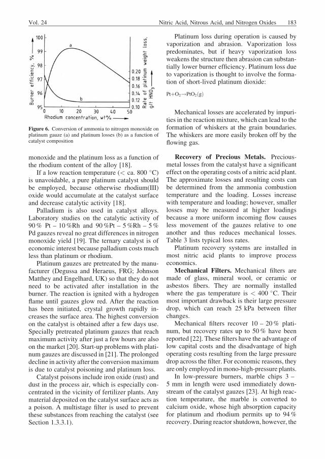
Platinum is usually alloyed with 5 – 10%rhodium to improve its strength and to reducecatalyst loss. During combustion, the metal sur-face becomes enriched in rhodium, thus improv-ing catalytic activity [17]. Because rhodium ismore expensive than platinum, a rhodium con-tent of 5 – 10% has proved optimal. Figure 6shows the efficiency of conversion to nitrogen
Figure 4. Conversion of ammonia to nitrogen monoxide ona platinum gauze as a funtion of temperature [5] a) 100 kPa;b) 400 kPa
Table 3. Typical design data for ammonia burners
Pressure, Number Gas Reaction Catalyst
MPa of gauzes velocity, temperature, loss, g/t
m/s �C HNO3
0.1 – 0.2 3 – 5 0.4 – 1.0 840 – 850 0.05 – 0.10
0.3 – 0.7 6 – 10 1 – 3 880 – 900 0.15 – 0.20
0.8 – 1.2 20 – 50 2 – 4 900 – 950 0.25 – 0.50
Figure 5. Losses of precious metals in the combustion ofammonia to nitrogen monoxide as a function of temperatureand catalyst composition [5] a) Pt; b) Pt – Rh 98/2; c) Pt –Rh 90/10
182 Nitric Acid, Nitrous Acid, and Nitrogen Oxides Vol. 24
monoxide and the platinum loss as a function ofthe rhodium content of the alloy [18].
If a low reaction temperature (< ca. 800 �C)is unavoidable, a pure platinum catalyst shouldbe employed, because otherwise rhodium(III)oxide would accumulate at the catalyst surfaceand decrease catalytic activity [18].
Palladium is also used in catalyst alloys.Laboratory studies on the catalytic activity of90% Pt – 10%Rh and 90%Pt – 5%Rh – 5%Pd gauzes reveal no great differences in nitrogenmonoxide yield [19]. The ternary catalyst is ofeconomic interest because palladium costs muchless than platinum or rhodium.
Platinum gauzes are pretreated by the manu-facturer (Degussa and Heraeus, FRG; JohnsonMatthey and Engelhard, UK) so that they do notneed to be activated after installation in theburner. The reaction is ignited with a hydrogenflame until gauzes glow red. After the reactionhas been initiated, crystal growth rapidly in-creases the surface area. The highest conversionon the catalyst is obtained after a few days use.Specially pretreated platinum gauzes that reachmaximum activity after just a few hours are alsoon the market [20]. Start-up problems with plati-num gauzes are discussed in [21]. The prolongeddecline in activity after the conversionmaximumis due to catalyst poisoning and platinum loss.
Catalyst poisons include iron oxide (rust) anddust in the process air, which is especially con-centrated in the vicinity of fertilizer plants. Anymaterial deposited on the catalyst surface acts asa poison. A multistage filter is used to preventthese substances from reaching the catalyst (seeSection 1.3.3.1).
Platinum loss during operation is caused byvaporization and abrasion. Vaporization losspredominates, but if heavy vaporization lossweakens the structure then abrasion can substan-tially lower burner efficiency. Platinum loss dueto vaporization is thought to involve the forma-tion of short-lived platinum dioxide:
PtþO2!PtO2ðgÞ
Mechanical losses are accelerated by impuri-ties in the reaction mixture, which can lead to theformation of whiskers at the grain boundaries.The whiskers are more easily broken off by theflowing gas.
Recovery of Precious Metals. Precious-metal losses from the catalyst have a significanteffect on the operating costs of a nitric acid plant.The approximate losses and resulting costs canbe determined from the ammonia combustiontemperature and the loading. Losses increasewith temperature and loading; however, smallerlosses may be measured at higher loadingsbecause a more uniform incoming flow causesless movement of the gauzes relative to oneanother and thus reduces mechanical losses.Table 3 lists typical loss rates.
Platinum recovery systems are installed inmost nitric acid plants to improve processeconomics.
Mechanical Filters. Mechanical filters aremade of glass, mineral wool, or ceramic orasbestos fibers. They are normally installedwhere the gas temperature is < 400 �C. Theirmost important drawback is their large pressuredrop, which can reach 25 kPa between filterchanges.
Mechanical filters recover 10 – 20% plati-num, but recovery rates up to 50% have beenreported [22]. These filters have the advantage oflow capital costs and the disadvantage of highoperating costs resulting from the large pressuredrop across the filter. For economic reasons, theyare only employed inmono-high-pressure plants.
In low-pressure burners, marble chips 3 –5 mm in length were used immediately down-stream of the catalyst gauzes [23]. At high reac-tion temperature, the marble is converted tocalcium oxide, whose high absorption capacityfor platinum and rhodium permits up to 94%recovery. During reactor shutdown, however, the
Figure 6. Conversion of ammonia to nitrogen monoxide onplatinum gauze (a) and platinum losses (b) as a function ofcatalyst composition
Vol. 24 Nitric Acid, Nitrous Acid, and Nitrogen Oxides 183
calcium oxide must be protected againstmoisture.
Recovery Gauzes. A technically elegantapproach to platinum recovery is to install, justdownstream of the catalyst gauzes, a materialthat is stable at high temperature and that canabsorb platinum oxide vapor and form an alloywith it. The first recovery gauzes in productionplants (supplied byDegussa in 1968) consisted ofa gold – palladium alloy (20/80). Nowadaysmost such gauzes are gold-free but have a lowcontent of nickel (ca. 5%) to enhance theirstrength. The gauzes have 100 – 1350 mesh/cm2
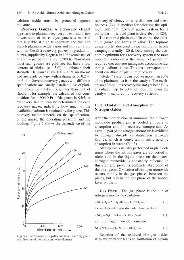
and are made of wire with a diameter of 0.2 –0.06 mm. Several recovery gauzes with differentspecifications are usually installed. Loss of plati-num from the catalyst is greater than that ofrhodium; for example, the calculated loss com-position for a 90/10 Pt – Rh gauze is 95/5. A‘‘recovery factor’’ can be determined for eachrecovery gauze, indicating how much of theavailable platinum is retained by the gauze. Thisrecovery factor depends on the specificationsof the gauze, the operating pressure, and theloading. Figure 7 shows the dependence of the
recovery efficiency on wire diameter and meshfineness [24]. A method for selecting the opti-mum platinum recovery gauze system for aparticular nitric acid plant is described in [25].
The captured platinum diffuses into the palla-dium gauze and forms an alloy. The topmostgauze is often designed to reach saturation in onecampaign, usually 180 d. Determining the eco-nomic optimum for a recovery system (the mostimportant criterion is the weight of palladiumrequired) necessitates taking into account the factthat palladium is lost. This loss corresponds toabout one-third of platinum recovery.
‘‘Getter’’ systems can recover more than 80%of the platinum lost from the catalyst. The mech-anism of rhodium recovery has not yet been fullyelucidated. Up to 30% of rhodium from thecatalyst is captured by recovery systems.
1.3.2. Oxidation and Absorption ofNitrogen Oxides
After the combustion of ammonia, the nitrogenmonoxide product gas is cooled en route toabsorption and, if necessary, compressed. Asa result, part of the nitrogenmonoxide is oxidizedto nitrogen dioxide or dinitrogen tetroxide(Eq. 2), which is converted to nitric acid byabsorption in water (Eq. 3).
Absorption is usually performed in plate col-umns where the nitrous gases are converted tonitric acid in the liquid phase on the plates.Nitrogen monoxide is constantly reformed inthis step and prevents complete absorption ofthe inlet gases. Oxidation of nitrogen monoxideoccurs mainly in the gas phases between theplates, but also in the gas phase of the bubblelayer on them.
Gas Phase. The gas phase is the site ofnitrogen monoxide oxidation
2 NOþO2!2 NO2 DH ¼ �1127 kJ=mol ð10Þas well as nitrogen dioxide dimerization
Reaction of the oxidized nitrogen oxideswith water vapor leads to formation of nitrous
Figure 7. Performance of a palladium-based recovery gauzeas a function of mesh size and wire diameter
184 Nitric Acid, Nitrous Acid, and Nitrogen Oxides Vol. 24
and nitric acids. These reactions are ofsecondary importance from an engineeringstandpoint.
To describe the kinetics of nitrogen monoxideoxidation (Eq. 10), a third-order rate equation isused [26]:
r ¼ kpRT
p2NOpO2 ð13Þ
wherer ¼ reaction rate, kmol m�3 s�1
kp ¼ reaction rate constant, atm�2 s�1
R ¼ universal gas constant, m3 atm kmol�1 K�1
T ¼ temperature, Kp ¼ partial pressure, atmThe rate constant is defined by
logkp ¼ 652:1
T�1:0366 ð14Þ
This reaction is unusual because it goes to theright faster at low temperature than at hightemperature, i.e., the reaction rate has a negativetemperature coefficient.
Because equilibrium in the nitrogen dioxidedimerization system is reached very quickly, anequilibrium formula
r ¼ kpRT
p2NO2� pN2O4
Kp
� �ð15Þ
can be assumed where Kp is the equilibriumconstant. The dimerization rate is virtually inde-pendent of temperature [27], so the rate constantat 25 �C
kp ¼ 5:7� 105atm�1s�1 ð16Þcan be used at all temperatures of technicalinterest.
HOFTYZER and KWANTEN [28] give the follow-ing equation for the NO2 – N2O4 equilibriumconstant:
Kp ¼ pN2O4
p2NO2
¼ 0:698� 10�9exp6866
T
� �ð17Þ
An equilibrium formula can also be written fordinitrogen trioxide formation:
r ¼ kpRT
pNOpNO2�pN2O3
Kp
� �ð18Þ
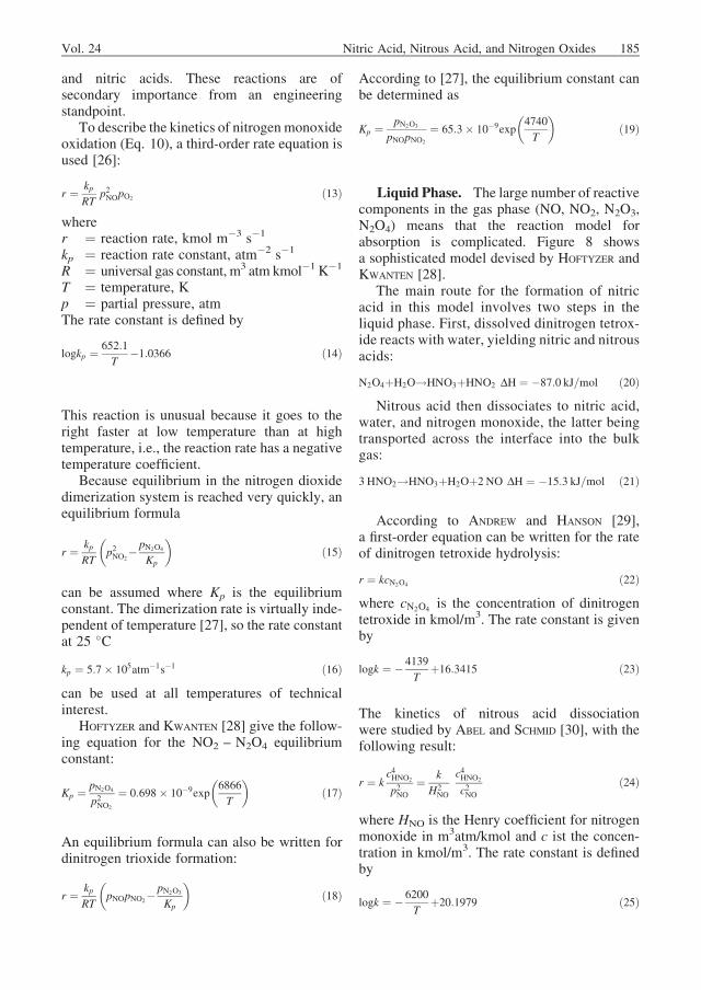
According to [27], the equilibrium constant canbe determined as
Kp ¼ pN2O3
pNOpNO2
¼ 65:3� 10�9exp4740
T
� �ð19Þ
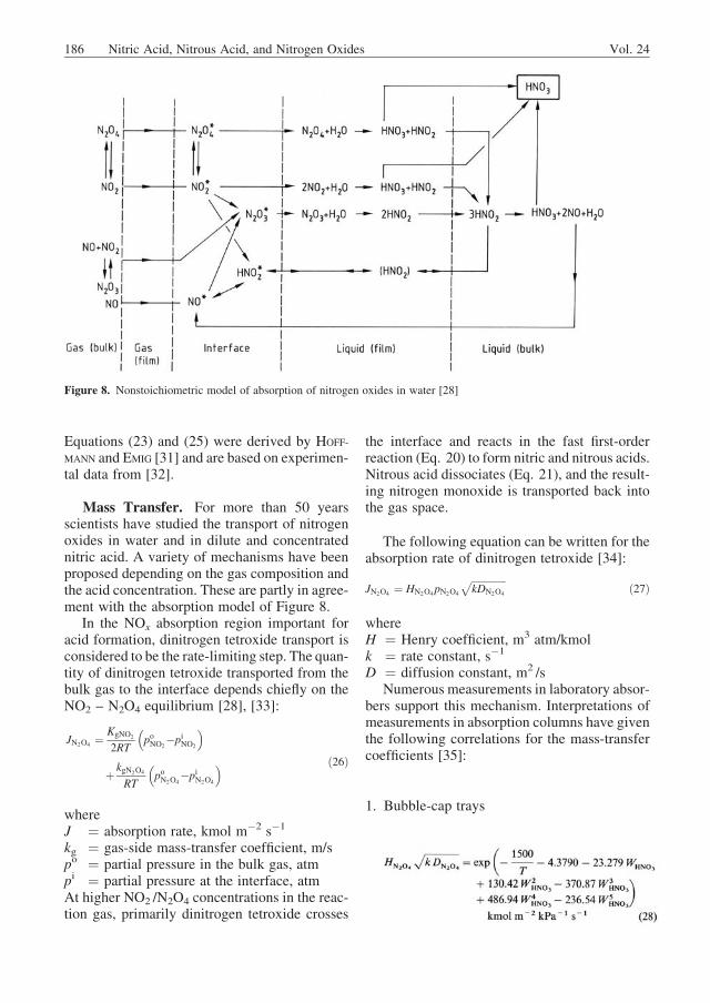
Liquid Phase. The large number of reactivecomponents in the gas phase (NO, NO2, N2O3,N2O4) means that the reaction model forabsorption is complicated. Figure 8 showsa sophisticated model devised by HOFTYZER andKWANTEN [28].
The main route for the formation of nitricacid in this model involves two steps in theliquid phase. First, dissolved dinitrogen tetrox-ide reacts with water, yielding nitric and nitrousacids:
N2O4þH2O!HNO3þHNO2 DH ¼ �87:0 kJ=mol ð20ÞNitrous acid then dissociates to nitric acid,
water, and nitrogen monoxide, the latter beingtransported across the interface into the bulkgas:
3 HNO2!HNO3þH2Oþ2 NO DH ¼ �15:3 kJ=mol ð21Þ
According to ANDREW and HANSON [29],a first-order equation can be written for the rateof dinitrogen tetroxide hydrolysis:
r ¼ kcN2O4 ð22Þwhere cN2O4 is the concentration of dinitrogentetroxide in kmol/m3. The rate constant is givenby
logk ¼ � 4139
Tþ16:3415 ð23Þ
The kinetics of nitrous acid dissociationwere studied by ABEL and SCHMID [30], with thefollowing result:
r ¼ kc4HNO2
p2NO¼ k
H2NO
c4HNO2
c2NOð24Þ
where HNO is the Henry coefficient for nitrogenmonoxide in m3atm/kmol and c ist the concen-tration in kmol/m3. The rate constant is definedby
logk ¼ � 6200
Tþ20:1979 ð25Þ
Vol. 24 Nitric Acid, Nitrous Acid, and Nitrogen Oxides 185
Equations (23) and (25) were derived by HOFF-
MANN and EMIG [31] and are based on experimen-tal data from [32].
Mass Transfer. For more than 50 yearsscientists have studied the transport of nitrogenoxides in water and in dilute and concentratednitric acid. A variety of mechanisms have beenproposed depending on the gas composition andthe acid concentration. These are partly in agree-ment with the absorption model of Figure 8.
In the NOx absorption region important foracid formation, dinitrogen tetroxide transport isconsidered to be the rate-limiting step. The quan-tity of dinitrogen tetroxide transported from thebulk gas to the interface depends chiefly on theNO2 – N2O4 equilibrium [28], [33]:
JN2O4 ¼KgNO2
2RT
�poNO2
�piNO2
�
þ kgN2O4
RT
�poN2O4
�piN2O4
� ð26Þ
whereJ ¼ absorption rate, kmol m�2 s�1
kg ¼ gas-side mass-transfer coefficient, m/spo ¼ partial pressure in the bulk gas, atmpi ¼ partial pressure at the interface, atmAt higher NO2 /N2O4 concentrations in the reac-tion gas, primarily dinitrogen tetroxide crosses
the interface and reacts in the fast first-orderreaction (Eq. 20) to form nitric and nitrous acids.Nitrous acid dissociates (Eq. 21), and the result-ing nitrogen monoxide is transported back intothe gas space.
The following equation can be written for theabsorption rate of dinitrogen tetroxide [34]:
JN2O4 ¼ HN2O4pN2O4
ffiffiffiffiffiffiffiffiffiffiffiffiffiffikDN2O4
p ð27Þ
whereH ¼ Henry coefficient, m3 atm/kmolk ¼ rate constant, s�1
D ¼ diffusion constant, m2 /sNumerous measurements in laboratory absor-
bers support this mechanism. Interpretations ofmeasurements in absorption columns have giventhe following correlations for the mass-transfercoefficients [35]:
1. Bubble-cap trays
Figure 8. Nonstoichiometric model of absorption of nitrogen oxides in water [28]
186 Nitric Acid, Nitrous Acid, and Nitrogen Oxides Vol. 24
2. Sieve trays
whereH ¼ Henry coefficient, m3kPa/kmolT ¼ temperature, KW ¼ mass fraction
The absorption of NO2 – N2O4 in concentrat-ed nitric acid can be treated as pure physicalabsorption [36]. Deviations from the describedchemisorption also occur at low gas-phaseNO2 – N2O4 concentrations [29].
Absorption Equilibrium. Equilibriumconsiderations allow determination of the maxi-mum possible acid concentration for a givencomposition of the inlet gas. For example,suppose the overall reaction is
3NO2ðgÞþH2OðlÞ�2HNO3ðlÞþNOðgÞ DH¼�72:8kJ=mol
ð30Þand the equilibrium constant is defined as
Kp¼p2HNO3
pNO
p3NO2pH2O
ð31Þ
with the partial pressures of nitrogen monoxide( pNO) and nitrogen dioxide (pNO2) in the gasphase and the vapor pressures of nitric acid(pHNO3) and water (pH2O) over the dilute acid. Inindustrial absorption the equilibrium constantdepends only on temperature. The equilibriumconstant is conventionally split into two terms:
Kp¼K1�K2
whereK1¼ pNOp3NO2
andK2¼p2HNO3
pH2O
ð32Þ
K2 depends on the acid concentration and thetemperature. Gases ( N2O4, N2O3, HNO2 ) dis-
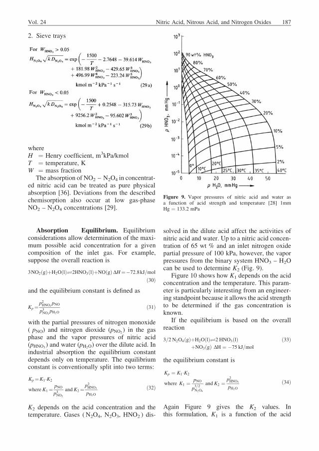
solved in the dilute acid affect the activities ofnitric acid and water. Up to a nitric acid concen-tration of 65 wt % and an inlet nitrogen oxidepartial pressure of 100 kPa, however, the vaporpressures from the binary system HNO3 – H2Ocan be used to determine K2 (Fig. 9).
Figure 10 shows how K1 depends on the acidconcentration and the temperature. This param-eter is particularly interesting from an engineer-ing standpoint because it allows the acid strengthto be determined if the gas concentration isknown.
If the equilibrium is based on the overallreaction
Again Figure 9 gives the K2 values. Inthis formulation, K1 is a function of the acid
Figure 9. Vapor pressures of nitric acid and water asa function of acid strength and temperature [28] 1mmHg ¼ 133.2 mPa
Vol. 24 Nitric Acid, Nitrous Acid, and Nitrogen Oxides 187
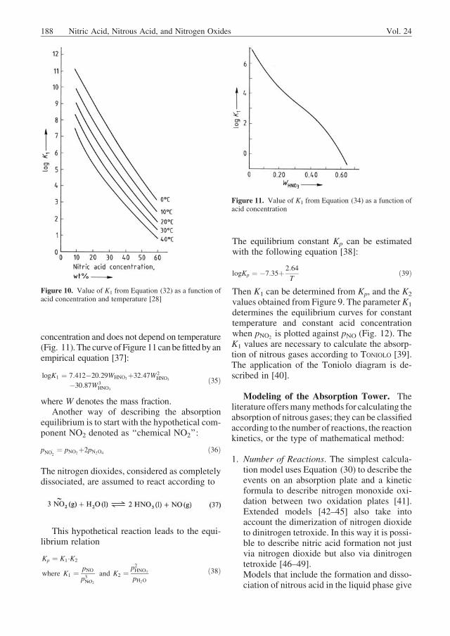
concentration and does not depend on temperature(Fig. 11).The curveofFigure 11canbefittedbyanempirical equation [37]:
logK1 ¼ 7:412�20:29WHNO3þ32:47W2HNO3
�30:87W3HNO3
ð35Þ
where W denotes the mass fraction.Another way of describing the absorption
equilibrium is to start with the hypothetical com-ponent NO2 denoted as ‘‘chemical NO2’’:
pNO~2 ¼ pNO2þ2pN2O4 ð36Þ
The nitrogen dioxides, considered as completelydissociated, are assumed to react according to
This hypothetical reaction leads to the equi-librium relation
Kp ¼ K1�K2
where K1 ¼ pNO
p3N~O2
and K2 ¼p2HNO3
pH2O
ð38Þ
The equilibrium constant Kp can be estimatedwith the following equation [38]:
logKp ¼ �7:35þ 2:64
Tð39Þ
Then K1 can be determined from Kp, and the K2
values obtained from Figure 9. The parameterK1
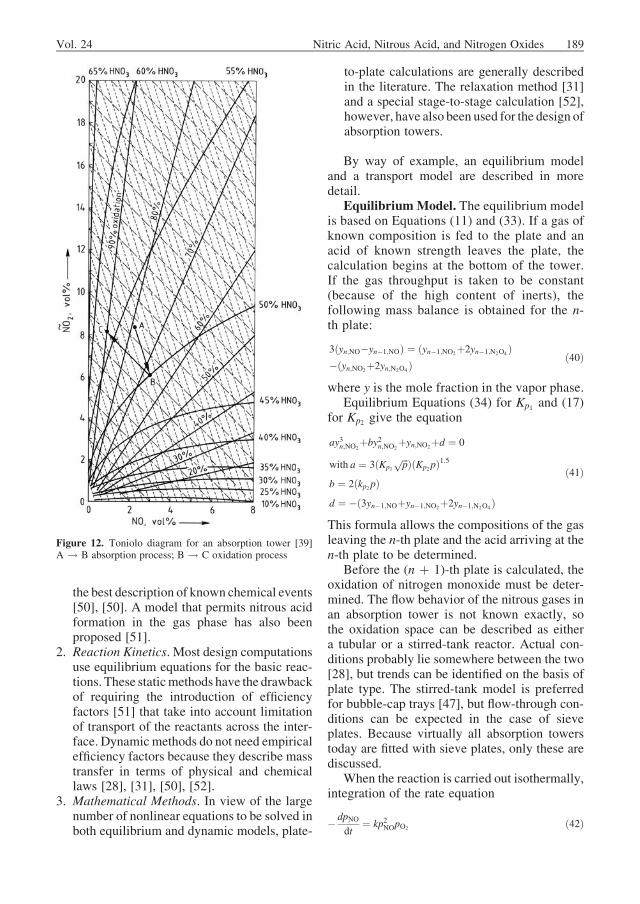
determines the equilibrium curves for constanttemperature and constant acid concentrationwhen pNO2 is plotted against pNO (Fig. 12). TheK1 values are necessary to calculate the absorp-tion of nitrous gases according to TONIOLO [39].The application of the Toniolo diagram is de-scribed in [40].
Modeling of the Absorption Tower. Theliterature offersmanymethods for calculating theabsorption of nitrous gases; they can be classifiedaccording to the number of reactions, the reactionkinetics, or the type of mathematical method:
1. Number of Reactions. The simplest calcula-tion model uses Equation (30) to describe theevents on an absorption plate and a kineticformula to describe nitrogen monoxide oxi-dation between two oxidation plates [41].Extended models [42–45] also take intoaccount the dimerization of nitrogen dioxideto dinitrogen tetroxide. In this way it is possi-ble to describe nitric acid formation not justvia nitrogen dioxide but also via dinitrogentetroxide [46–49].Models that include the formation and disso-ciation of nitrous acid in the liquid phase give
Figure 10. Value of K1 from Equation (32) as a function ofacid concentration and temperature [28]
Figure 11. Value of K1 from Equation (34) as a function ofacid concentration
188 Nitric Acid, Nitrous Acid, and Nitrogen Oxides Vol. 24
the best description of known chemical events[50], [50]. A model that permits nitrous acidformation in the gas phase has also beenproposed [51].
2. Reaction Kinetics. Most design computationsuse equilibrium equations for the basic reac-tions. These staticmethods have the drawbackof requiring the introduction of efficiencyfactors [51] that take into account limitationof transport of the reactants across the inter-face. Dynamicmethods do not need empiricalefficiency factors because they describe masstransfer in terms of physical and chemicallaws [28], [31], [50], [52].
3. Mathematical Methods. In view of the largenumber of nonlinear equations to be solved inboth equilibrium and dynamic models, plate-
to-plate calculations are generally describedin the literature. The relaxation method [31]and a special stage-to-stage calculation [52],however, have also been used for the design ofabsorption towers.
By way of example, an equilibrium modeland a transport model are described in moredetail.
EquilibriumModel. The equilibrium modelis based on Equations (11) and (33). If a gas ofknown composition is fed to the plate and anacid of known strength leaves the plate, thecalculation begins at the bottom of the tower.If the gas throughput is taken to be constant(because of the high content of inerts), thefollowing mass balance is obtained for the n-th plate:
where y is the mole fraction in the vapor phase.Equilibrium Equations (34) for Kp1 and (17)
for Kp2 give the equation
ay3n;NO2þby2n;NO2
þyn;NO2þd ¼ 0
with a ¼ 3ðKp1
ffiffiffip
p ÞðKp2pÞ1:5
b ¼ 2ðkp2pÞd ¼ �ð3yn�1;NOþyn�1;NO2þ2yn�1;N2O4 Þ
ð41Þ
This formula allows the compositions of the gasleaving the n-th plate and the acid arriving at then-th plate to be determined.
Before the (n þ 1)-th plate is calculated, theoxidation of nitrogen monoxide must be deter-mined. The flow behavior of the nitrous gases inan absorption tower is not known exactly, sothe oxidation space can be described as eithera tubular or a stirred-tank reactor. Actual con-ditions probably lie somewhere between the two[28], but trends can be identified on the basis ofplate type. The stirred-tank model is preferredfor bubble-cap trays [47], but flow-through con-ditions can be expected in the case of sieveplates. Because virtually all absorption towerstoday are fitted with sieve plates, only these arediscussed.
When the reaction is carried out isothermally,integration of the rate equation
� dpNOdt
¼ kp2NOpO2 ð42Þ
Figure 12. Toniolo diagram for an absorption tower [39]A ! B absorption process; B ! C oxidation process
Vol. 24 Nitric Acid, Nitrous Acid, and Nitrogen Oxides 189
gives a solution
q ¼ 2
kð2pO2�pNOÞ �(x
pNOð1�xÞ�1
2pO2�pNOln
2pO2�pNOx
2pO2 ð1�xÞ
24
35) ð43Þ
whereq ¼ residence time, sk ¼ rate constant, atm�2 s�1
p ¼ partial pressure, atmt ¼ time, sx ¼ fraction of oxidized nitrogen monoxidein which x must be determined by iteration fromthe residence time q and the inlet partial pressuresof nitrogen monoxide ( pNO) and oxygen (pO2)[47]. The partial pressures of the other compo-nents leaving the reactor can be calculated fromthe fraction x of oxidized nitrogen monoxide.
If an excess of oxygen is assumed to bepresent, the rate equation can be simplified[53] as
� dpNOdt
¼ kp2NO ð44Þ
so that the partial pressure of nitrogen monoxideat the reactor outlet ( p0NO) can be determined:
1
p0NO
¼ 1
pNOþð2pO2�pNOÞ kq
2ð45Þ
Because the oxidation reaction is highly exother-mic, the tubular reactor can be designed forisothermal operation only when conversion isvery low (e.g., when the tail gas contains littleNO). Otherwise, adiabatic reaction conditionsmust be assumed. To describe the reaction underadiabatic conditions the oxidation space is divid-ed into n layers, in each of which the reaction isisothermal. The temperature increase from onelayer to the next is given by [33]
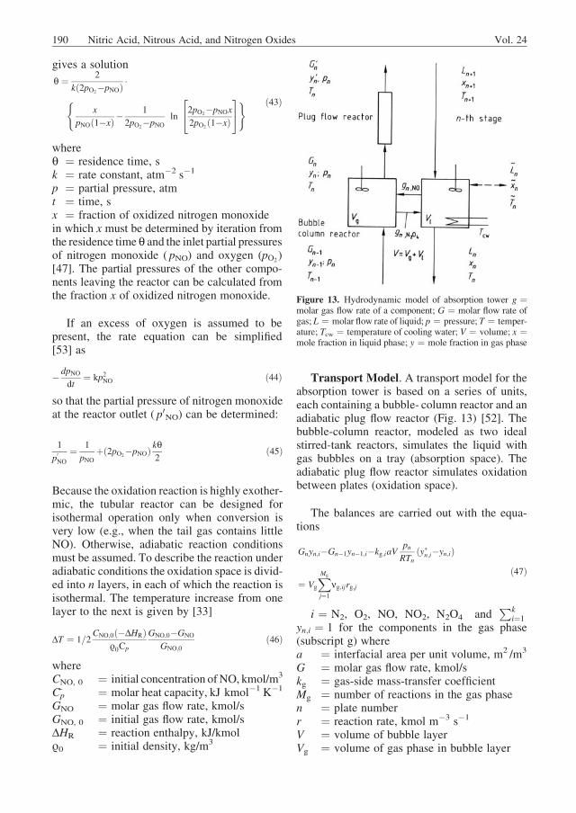
Transport Model. A transport model for theabsorption tower is based on a series of units,each containing a bubble- column reactor and anadiabatic plug flow reactor (Fig. 13) [52]. Thebubble-column reactor, modeled as two idealstirred-tank reactors, simulates the liquid withgas bubbles on a tray (absorption space). Theadiabatic plug flow reactor simulates oxidationbetween plates (oxidation space).
The balances are carried out with the equa-tions
Gnyn;i�Gn�1yn�1;i�kg;iaVpnRTn
ðy�n;i�yn;iÞ
¼ Vg
XMg
j¼1
ng;ijrg;jð47Þ
i ¼ N2, O2, NO, NO2, N2O4 andPk
i¼1
yn;i ¼ 1 for the components in the gas phase(subscript g) wherea ¼ interfacial area per unit volume, m2 /m3
G ¼ molar gas flow rate, kmol/skg ¼ gas-side mass-transfer coefficientMg ¼ number of reactions in the gas phasen ¼ plate numberr ¼ reaction rate, kmol m�3 s�1
V ¼ volume of bubble layerVg ¼ volume of gas phase in bubble layer
Figure 13. Hydrodynamic model of absorption tower g ¼molar gas flow rate of a component; G ¼ molar flow rate ofgas; L ¼ molar flow rate of liquid; p ¼ pressure; T ¼ temper-ature; Tcw ¼ temperature of cooling water; V ¼ volume; x ¼mole fraction in liquid phase; y ¼ mole fraction in gas phase
190 Nitric Acid, Nitrous Acid, and Nitrogen Oxides Vol. 24
yi ¼ mole fraction of i-th component in liquidphase
y *i ¼ mole fraction of i-th component in liquidphase at the phase boundary
n ¼ stoichiometric coefficientAnalogously for the liquid phase (subscript l)
Lnxn;i�Lnþ1xnþ1;iþkl;iaVcnðx�n;i�xn;iÞ
�~Ln~xn;i ¼ Vl
XMl
j¼1
nl;ijrl;jð48Þ
i ¼ NO, N2O4, HNO2, HNO3, H2O andPki¼1
xn;i ¼ 1 where
c ¼ molar concentration, kmol/m3
L ¼ molar liquid flow rate, kmol/sx ¼ mole fraction in liquid phase~L ¼ side streamMl ¼ number of reactions in the liquid phaseThermodynamic equilibrium is assumed at theinterface,
y�n;i ¼ Hn;ix�n;i ð49Þ
whereH is the Henry coefficient and the formula
kg;ipnRTn
ðyn;i�y�n;iÞ ¼ kl;icnðx�n;i�xn;iÞ
i ¼ NO;N2O4
ð50Þ
is used for dynamic mass transfer betweenphases. A separate heat balance is performedfor each phase, so that the temperature may
differ in both phases of a single stage. Themathematical treatment of this model is de-scribed in [52].
1.3.3. Equipment
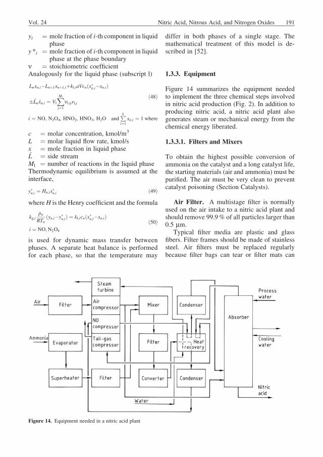
Figure 14 summarizes the equipment neededto implement the three chemical steps involvedin nitric acid production (Fig. 2). In addition toproducing nitric acid, a nitric acid plant alsogenerates steam or mechanical energy from thechemical energy liberated.
1.3.3.1. Filters and Mixers
To obtain the highest possible conversion ofammonia on the catalyst and a long catalyst life,the starting materials (air and ammonia) must bepurified. The air must be very clean to preventcatalyst poisoning (Section Catalysts).
Air Filter. A multistage filter is normallyused on the air intake to a nitric acid plant andshould remove 99.9% of all particles larger than0.5 mm.
Typical filter media are plastic and glassfibers. Filter frames should be made of stainlesssteel. Air filters must be replaced regularlybecause filter bags can tear or filter mats can
Figure 14. Equipment needed in a nitric acid plant
Vol. 24 Nitric Acid, Nitrous Acid, and Nitrogen Oxides 191
become overloaded and cause an excessivepressure drop. Filter life depends on the particu-late load in the air (typically 0.8 mg/m3 ). Inareas where sandstorms may occur (maximumloading 500 mg/m3 ), the use of a sandseparator (a centrifugal collector) as a prefilteris recommended.
Ammonia Filters. The liquid ammonia fil-ter removes solid contaminants, especially smallrust particles; 99.9% of all particles larger than3 mm should be eliminated. Selection of a liquidammonia filter requires consideration of the factthat traces of oils and chlorides are also present inammonia. Proven filter materials are Teflon andsinteredmetals. Polypropylene and ceramic filtercandles (cartridges) are also employed.Magneticfilters have found some use but have limitedcapacity.
Filtration of ammonia gas should remove99.9% of oil and solid particles larger than0.5 mm. The principal filter media are glassfibers, sintered metals, and ceramics. The pres-sure drop is up to 10 kPa, depending on filtertype.
Filters for the Mixed Gas. The mixed-gasfilter provides final cleaning of the ammonia –air mixture and improves the mixing of the airand ammonia; it should remove 99.8% of allparticles larger than 1.5 mm. Contaminants in thegas mixture not only originate externally (in theprocess air and ammonia) but are also formed bycorrosion inside the system (rust). The gas mix-ture filter should therefore be installed as near aspossible to the burner. Ceramic filter cartridgesare generally used in which silicon dioxide is thedominant constituent. For a filter cartridge witha surface loading of 250 m3 /m2, the maximumpressure drop in the clean state is 10 kPa.
Mixers. Static gas mixers are used for twopurposes in nitric acid plants:
1. To mix ammonia and air in a ratio of ca. 1 : 10for catalytic oxidation (see Section 1.3.1)
2. To mix ammonia and tail gas in a ratio of1 : 100 for the catalytic reduction of NOx aspart of tail-gas treatment (see Section 1.4.2.3).
From an economic standpoint, homogeneousmixing of the gas streams upstream of the reactor
is important in both cases. Local ammoniaexcesses in the burner are a risk for plantsafety (explosion limit) and may also causeoverheating of the catalyst gauze. Poor mixinglowers the conversion of ammonia to nitrogenmonoxide and increases platinum loss from thecatalyst.
The efficiency of a given mixing operation isdescribed by the standard deviation s of mea-sured samples from the theoretical value �xa certain distance downstream from mixing. Innitric acid plants, the deviation should be< 1%. If the theoretical ammonia concentra-tion in a mixture is 10%, for example, mea-sured values fluctuate between 9.9 and 10.1%[54]. Only static mixers are used (e.g., the Uhdetubular mixer or the Sulzer three-elementmixer).
1.3.3.2. Burners and Waste-Heat Boilers
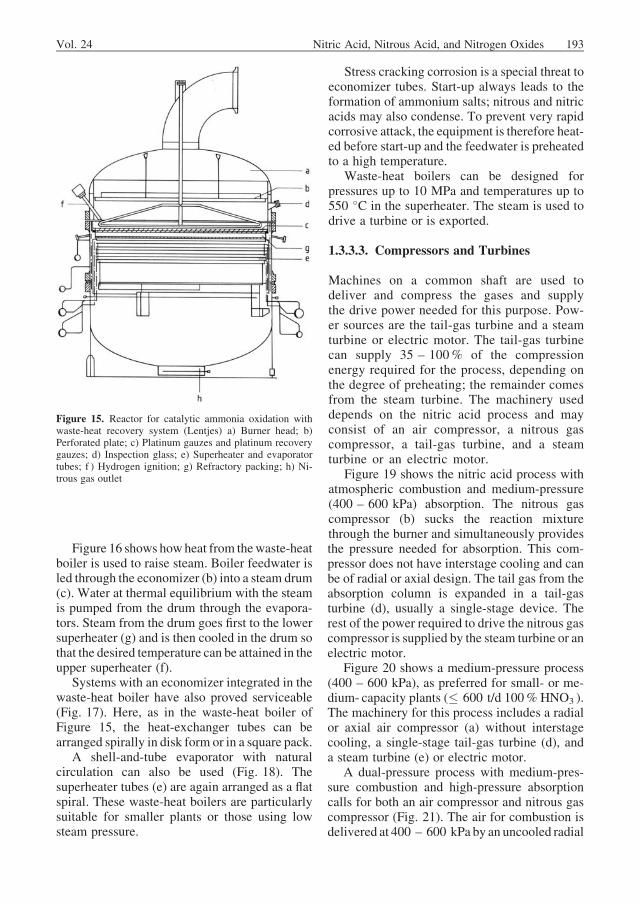
The heat of reaction liberated during ammoniacombustion is utilized to produce steam andpreheat the tail gas. Steam is produced in awaste-heat boiler located immediately below theburner (Fig. 15). The burner consists of a burnerbasket packed with filling material to ensureuniform distrubution of the downward flowingreaction gas. Platinum recovery gauzes (SectionRecovery of Precious Metals) are located abovethe filling material. The catalyst gauzes (SectionCatalysts) are located above the recovery gauzes.The burner basket is clamped between the flangesof the burner head and the waste-heat boiler. Toensure better distribution of the reaction mixture,the burner head also contains a perforated plate orhoneycomb grid. Hydrogen burners rotatingabove the surface are often used for ignition.The gauze temperature is measured, and thespace above the gauze can be observed throughinspection glasses. The gauzes glow bright redduring catalysis. The throughput per element canproduce up to 1200 t of 100% nitric acid per day.
Waste-heat boilers up to 6 m in diameter areused. Figure 15 shows a waste-heat boiler formedium-pressure burning. The preevaporator islocated directly below the burner basket andprotects the downstream superheater against ex-cessive temperature. The superheater is followedby themain evaporator. Evaporator tubes are alsoinstalled at the wall to cool it and protect it fromexcessive temperature.
192 Nitric Acid, Nitrous Acid, and Nitrogen Oxides Vol. 24
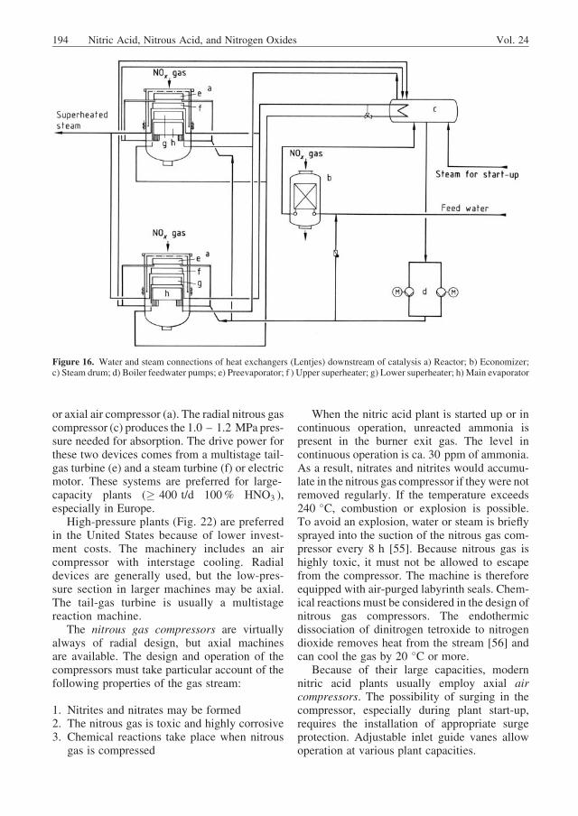
Figure 16 shows howheat from thewaste-heatboiler is used to raise steam. Boiler feedwater isled through the economizer (b) into a steam drum(c). Water at thermal equilibrium with the steamis pumped from the drum through the evapora-tors. Steam from the drum goes first to the lowersuperheater (g) and is then cooled in the drum sothat the desired temperature can be attained in theupper superheater (f).
Systems with an economizer integrated in thewaste-heat boiler have also proved serviceable(Fig. 17). Here, as in the waste-heat boiler ofFigure 15, the heat-exchanger tubes can bearranged spirally in disk form or in a square pack.
A shell-and-tube evaporator with naturalcirculation can also be used (Fig. 18). Thesuperheater tubes (e) are again arranged as a flatspiral. These waste-heat boilers are particularlysuitable for smaller plants or those using lowsteam pressure.
Stress cracking corrosion is a special threat toeconomizer tubes. Start-up always leads to theformation of ammonium salts; nitrous and nitricacids may also condense. To prevent very rapidcorrosive attack, the equipment is therefore heat-ed before start-up and the feedwater is preheatedto a high temperature.
Waste-heat boilers can be designed forpressures up to 10 MPa and temperatures up to550 �C in the superheater. The steam is used todrive a turbine or is exported.
1.3.3.3. Compressors and Turbines
Machines on a common shaft are used todeliver and compress the gases and supplythe drive power needed for this purpose. Pow-er sources are the tail-gas turbine and a steamturbine or electric motor. The tail-gas turbinecan supply 35 – 100% of the compressionenergy required for the process, depending onthe degree of preheating; the remainder comesfrom the steam turbine. The machinery useddepends on the nitric acid process and mayconsist of an air compressor, a nitrous gascompressor, a tail-gas turbine, and a steamturbine or an electric motor.
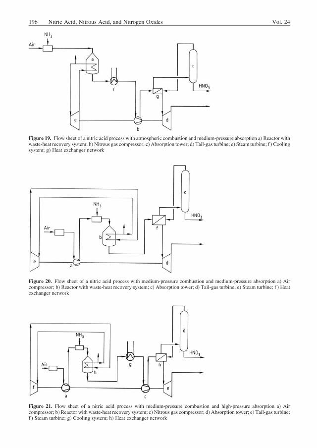
Figure 19 shows the nitric acid process withatmospheric combustion and medium-pressure(400 – 600 kPa) absorption. The nitrous gascompressor (b) sucks the reaction mixturethrough the burner and simultaneously providesthe pressure needed for absorption. This com-pressor does not have interstage cooling and canbe of radial or axial design. The tail gas from theabsorption column is expanded in a tail-gasturbine (d), usually a single-stage device. Therest of the power required to drive the nitrous gascompressor is supplied by the steam turbine or anelectric motor.
Figure 20 shows a medium-pressure process(400 – 600 kPa), as preferred for small- or me-dium- capacity plants (� 600 t/d 100% HNO3 ).The machinery for this process includes a radialor axial air compressor (a) without interstagecooling, a single-stage tail-gas turbine (d), anda steam turbine (e) or electric motor.
A dual-pressure process with medium-pres-sure combustion and high-pressure absorptioncalls for both an air compressor and nitrous gascompressor (Fig. 21). The air for combustion isdelivered at 400 – 600 kPa by an uncooled radial
Figure 15. Reactor for catalytic ammonia oxidation withwaste-heat recovery system (Lentjes) a) Burner head; b)Perforated plate; c) Platinum gauzes and platinum recoverygauzes; d) Inspection glass; e) Superheater and evaporatortubes; f ) Hydrogen ignition; g) Refractory packing; h) Ni-trous gas outlet
Vol. 24 Nitric Acid, Nitrous Acid, and Nitrogen Oxides 193
or axial air compressor (a). The radial nitrous gascompressor (c) produces the 1.0 – 1.2 MPa pres-sure needed for absorption. The drive power forthese two devices comes from a multistage tail-gas turbine (e) and a steam turbine (f) or electricmotor. These systems are preferred for large-capacity plants (� 400 t/d 100% HNO3 ),especially in Europe.
High-pressure plants (Fig. 22) are preferredin the United States because of lower invest-ment costs. The machinery includes an aircompressor with interstage cooling. Radialdevices are generally used, but the low-pres-sure section in larger machines may be axial.The tail-gas turbine is usually a multistagereaction machine.
The nitrous gas compressors are virtuallyalways of radial design, but axial machinesare available. The design and operation of thecompressors must take particular account of thefollowing properties of the gas stream:
1. Nitrites and nitrates may be formed2. The nitrous gas is toxic and highly corrosive3. Chemical reactions take place when nitrous
gas is compressed
When the nitric acid plant is started up or incontinuous operation, unreacted ammonia ispresent in the burner exit gas. The level incontinuous operation is ca. 30 ppm of ammonia.As a result, nitrates and nitrites would accumu-late in the nitrous gas compressor if theywere notremoved regularly. If the temperature exceeds240 �C, combustion or explosion is possible.To avoid an explosion, water or steam is brieflysprayed into the suction of the nitrous gas com-pressor every 8 h [55]. Because nitrous gas ishighly toxic, it must not be allowed to escapefrom the compressor. The machine is thereforeequipped with air-purged labyrinth seals. Chem-ical reactions must be considered in the design ofnitrous gas compressors. The endothermicdissociation of dinitrogen tetroxide to nitrogendioxide removes heat from the stream [56] andcan cool the gas by 20 �C or more.
Because of their large capacities, modernnitric acid plants usually employ axial aircompressors. The possibility of surging in thecompressor, especially during plant start-up,requires the installation of appropriate surgeprotection. Adjustable inlet guide vanes allowoperation at various plant capacities.
Figure 16. Water and steam connections of heat exchangers (Lentjes) downstream of catalysis a) Reactor; b) Economizer;c) Steam drum; d) Boiler feedwater pumps; e) Preevaporator; f ) Upper superheater; g) Lower superheater; h) Main evaporator
194 Nitric Acid, Nitrous Acid, and Nitrogen Oxides Vol. 24
Tail-gas turbines can be single-stage ormultistage devices of axial or radial design. Forpart-load operation, these machines are equippedwith a group of valve-controlled nozzles oradjustable guide vanes in the inlet.
Steam turbines may be condensing or back-pressure machines with or without an extraction/side stream.
1.3.3.4. Heat Exchangers and Columns
Heat Exchangers. The shell-and-tube de-sign predominates for tail-gas heat exchangers,
with hot nitrous gas on the tube side and cool tailgas on the shell side. The pressure drop should bekept as low as possible to secure a favorableenergy balance for the plant as a whole.
Ammonia Evaporator. Various types ofequipment can be used for ammonia evapora-tion. Figure 23 shows a shell-and-tube heatexchanger with mist collector. Cooling wateron the tube side is cooled on evaporation. Inmedium-pressure plants, the heat of vaporiza-tion is also taken from chilled water used ascoolant in the absorption step. The shell-sideheat-transfer coefficients for ammonia can becalculated according to [57].
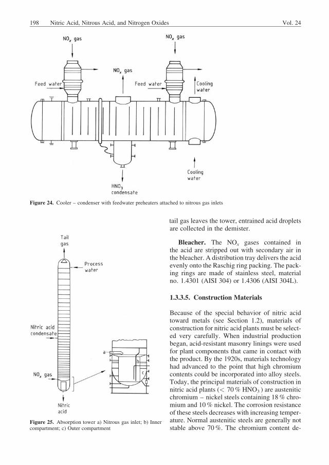
Gas Cooler – Condenser. In the cooler –condenser, the temperature is lowered below thedew point of the inlet nitrous gas. The nitric acidcondensate has a concentration of, for example,ca. 40 wt % at medium pressure. Suitable mate-rials of construction are discussed in Section1.3.3.5. The thermal design of a gas cooler –condenser is difficult because the cooling stepinvolves chemical reactions in both the gas andthe condensed liquid phases. In the apparatusshown in Figure 24, nitrous gas passes into theshell side through two inlets; each of the partial
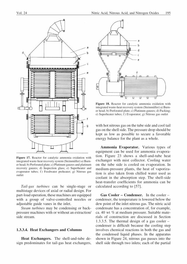
Figure 17. Reactor for catalytic ammonia oxidation withintegrated waste-heat recovery system (Steinm€uller) a) Burn-er head; b) Perforated plate; c) Platinum gauzes and platinumrecovery gauzes; d) Inspection glass; e) Superheater andevaporator tubes; f ) Feedwater preheater; g) Nitrous gasoutlet
Figure 18. Reactor for catalytic ammonia oxidation withintegrated waste-heat recovery system (Steinm€uller) a) Burn-er head; b) Perforated plate; c) Platinum gauzes; d) Packing;e) Superheater tubes; f ) Evaporator; g) Nitrous gas outlet
Vol. 24 Nitric Acid, Nitrous Acid, and Nitrogen Oxides 195
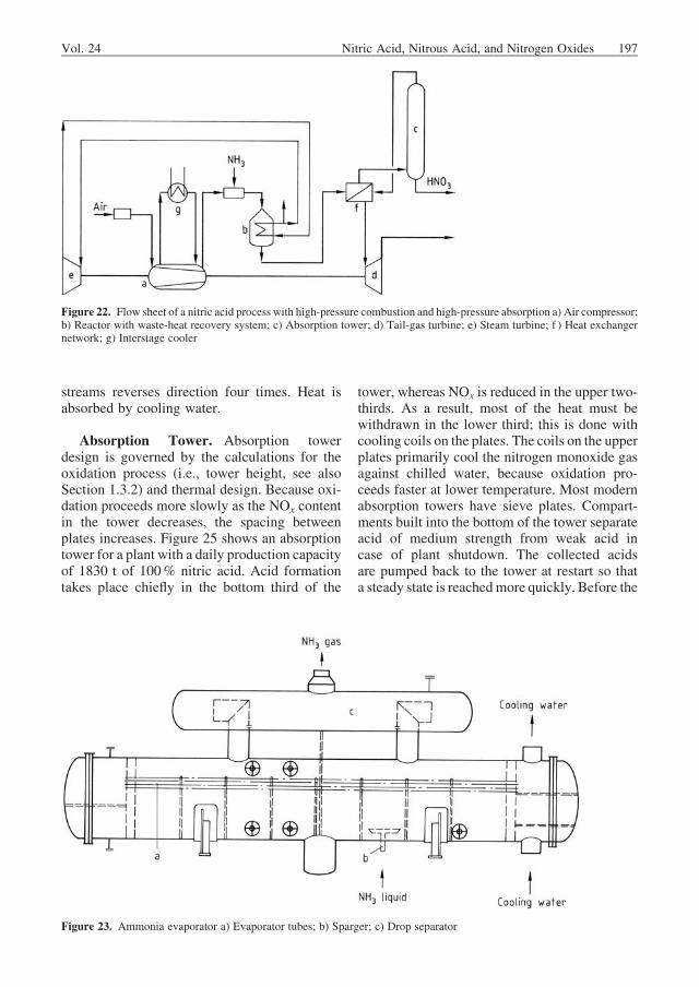
Figure 19. Flow sheet of a nitric acid process with atmospheric combustion and medium-pressure absorption a) Reactor withwaste-heat recovery system; b) Nitrous gas compressor; c) Absorption tower; d) Tail-gas turbine; e) Steam turbine; f ) Coolingsystem; g) Heat exchanger network
Figure 20. Flow sheet of a nitric acid process with medium-pressure combustion and medium-pressure absorption a) Aircompressor; b) Reactor with waste-heat recovery system; c) Absorption tower; d) Tail-gas turbine; e) Steam turbine; f ) Heatexchanger network
Figure 21. Flow sheet of a nitric acid process with medium-pressure combustion and high-pressure absorption a) Aircompressor; b) Reactor with waste-heat recovery system; c) Nitrous gas compressor; d) Absorption tower; e) Tail-gas turbine;f ) Steam turbine; g) Cooling system; h) Heat exchanger network
196 Nitric Acid, Nitrous Acid, and Nitrogen Oxides Vol. 24
streams reverses direction four times. Heat isabsorbed by cooling water.
Absorption Tower. Absorption towerdesign is governed by the calculations for theoxidation process (i.e., tower height, see alsoSection 1.3.2) and thermal design. Because oxi-dation proceeds more slowly as the NOx contentin the tower decreases, the spacing betweenplates increases. Figure 25 shows an absorptiontower for a plant with a daily production capacityof 1830 t of 100% nitric acid. Acid formationtakes place chiefly in the bottom third of the
tower, whereas NOx is reduced in the upper two-thirds. As a result, most of the heat must bewithdrawn in the lower third; this is done withcooling coils on the plates. The coils on the upperplates primarily cool the nitrogen monoxide gasagainst chilled water, because oxidation pro-ceeds faster at lower temperature. Most modernabsorption towers have sieve plates. Compart-ments built into the bottom of the tower separateacid of medium strength from weak acid incase of plant shutdown. The collected acidsare pumped back to the tower at restart so thata steady state is reachedmore quickly. Before the
Figure 22. Flow sheet of a nitric acid process with high-pressure combustion and high-pressure absorption a) Air compressor;b) Reactor with waste-heat recovery system; c) Absorption tower; d) Tail-gas turbine; e) Steam turbine; f ) Heat exchangernetwork; g) Interstage cooler
Figure 23. Ammonia evaporator a) Evaporator tubes; b) Sparger; c) Drop separator
Vol. 24 Nitric Acid, Nitrous Acid, and Nitrogen Oxides 197
tail gas leaves the tower, entrained acid dropletsare collected in the demister.
Bleacher. The NOx gases contained inthe acid are stripped out with secondary air inthe bleacher. A distribution tray delivers the acidevenly onto the Raschig ring packing. The pack-ing rings are made of stainless steel, materialno. 1.4301 (AISI 304) or 1.4306 (AISI 304L).
1.3.3.5. Construction Materials
Because of the special behavior of nitric acidtoward metals (see Section 1.2), materials ofconstruction for nitric acid plants must be select-ed very carefully. When industrial productionbegan, acid-resistant masonry linings were usedfor plant components that came in contact withthe product. By the 1920s, materials technologyhad advanced to the point that high chromiumcontents could be incorporated into alloy steels.Today, the principal materials of construction innitric acid plants (< 70% HNO3 ) are austeniticchromium – nickel steels containing 18% chro-mium and 10% nickel. The corrosion resistanceof these steels decreases with increasing temper-ature. Normal austenitic steels are generally notstable above 70%. The chromium content de-
Figure 24. Cooler – condenser with feedwater preheaters attached to nitrous gas inlets
Figure 25. Absorption tower a) Nitrous gas inlet; b) Innercompartment; c) Outer compartment
198 Nitric Acid, Nitrous Acid, and Nitrogen Oxides Vol. 24
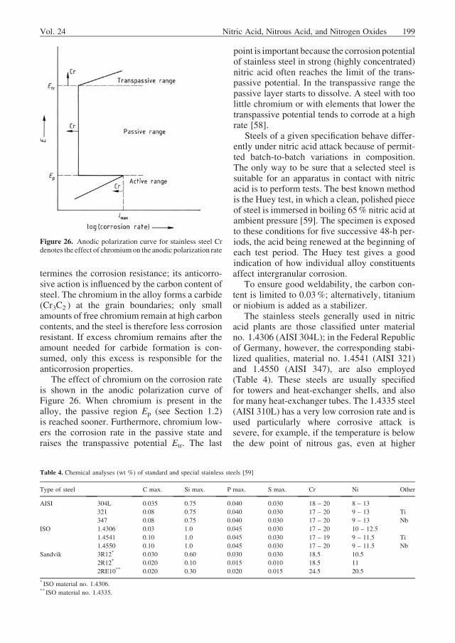
termines the corrosion resistance; its anticorro-sive action is influenced by the carbon content ofsteel. The chromium in the alloy forms a carbide(Cr3C2 ) at the grain boundaries; only smallamounts of free chromium remain at high carboncontents, and the steel is therefore less corrosionresistant. If excess chromium remains after theamount needed for carbide formation is con-sumed, only this excess is responsible for theanticorrosion properties.
The effect of chromium on the corrosion rateis shown in the anodic polarization curve ofFigure 26. When chromium is present in thealloy, the passive region Ep (see Section 1.2)is reached sooner. Furthermore, chromium low-ers the corrosion rate in the passive state andraises the transpassive potential Etr. The last
point is important because the corrosion potentialof stainless steel in strong (highly concentrated)nitric acid often reaches the limit of the trans-passive potential. In the transpassive range thepassive layer starts to dissolve. A steel with toolittle chromium or with elements that lower thetranspassive potential tends to corrode at a highrate [58].
Steels of a given specification behave differ-ently under nitric acid attack because of permit-ted batch-to-batch variations in composition.The only way to be sure that a selected steel issuitable for an apparatus in contact with nitricacid is to perform tests. The best known methodis the Huey test, in which a clean, polished pieceof steel is immersed in boiling 65% nitric acid atambient pressure [59]. The specimen is exposedto these conditions for five successive 48-h per-iods, the acid being renewed at the beginning ofeach test period. The Huey test gives a goodindication of how individual alloy constituentsaffect intergranular corrosion.
To ensure good weldability, the carbon con-tent is limited to 0.03%; alternatively, titaniumor niobium is added as a stabilizer.
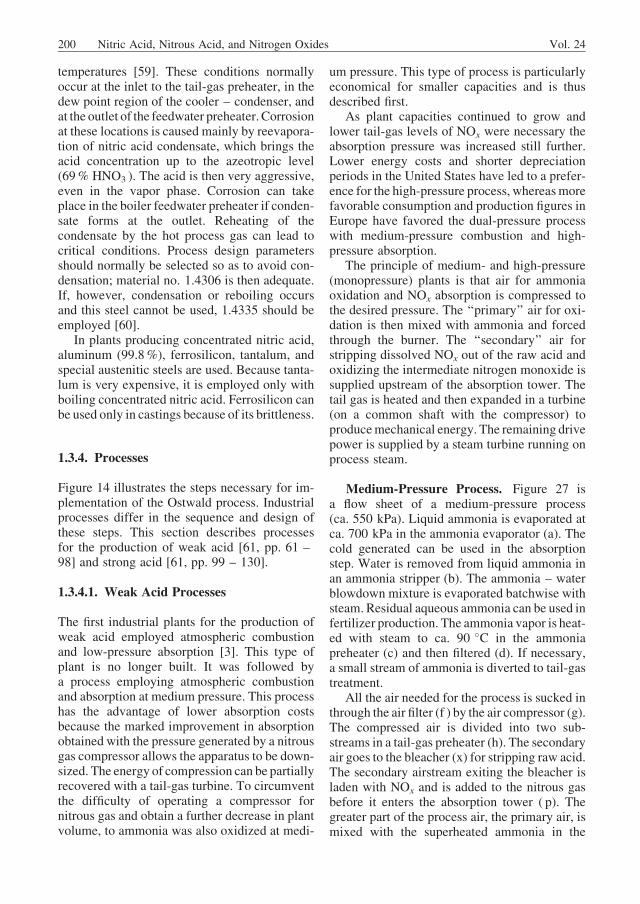
The stainless steels generally used in nitricacid plants are those classified unter materialno. 1.4306 (AISI 304L); in the Federal Republicof Germany, however, the corresponding stabi-lized qualities, material no. 1.4541 (AISI 321)and 1.4550 (AISI 347), are also employed(Table 4). These steels are usually specifiedfor towers and heat-exchanger shells, and alsofor many heat-exchanger tubes. The 1.4335 steel(AISI 310L) has a very low corrosion rate and isused particularly where corrosive attack issevere, for example, if the temperature is belowthe dew point of nitrous gas, even at higher
Figure 26. Anodic polarization curve for stainless steel Crdenotes the effect of chromiumon the anodic polarization rate
Table 4. Chemical analyses (wt %) of standard and special stainless steels [59]
Type of steel C max. Si max. P max. S max. Cr Ni Other
AISI 304L 0.035 0.75 0.040 0.030 18 – 20 8 – 13
321 0.08 0.75 0.040 0.030 17 – 20 9 – 13 Ti
347 0.08 0.75 0.040 0.030 17 – 20 9 – 13 Nb
ISO 1.4306 0.03 1.0 0.045 0.030 17 – 20 10 – 12.5
1.4541 0.10 1.0 0.045 0.030 17 – 19 9 – 11.5 Ti
1.4550 0.10 1.0 0.045 0.030 17 – 20 9 – 11.5 Nb
Sandvik 3R12* 0.030 0.60 0.030 0.030 18.5 10.5
2R12* 0.020 0.10 0.015 0.010 18.5 11
2RE10** 0.020 0.30 0.020 0.015 24.5 20.5
* ISO material no. 1.4306.** ISO material no. 1.4335.
Vol. 24 Nitric Acid, Nitrous Acid, and Nitrogen Oxides 199
temperatures [59]. These conditions normallyoccur at the inlet to the tail-gas preheater, in thedew point region of the cooler – condenser, andat the outlet of the feedwater preheater. Corrosionat these locations is caused mainly by reevapora-tion of nitric acid condensate, which brings theacid concentration up to the azeotropic level(69% HNO3 ). The acid is then very aggressive,even in the vapor phase. Corrosion can takeplace in the boiler feedwater preheater if conden-sate forms at the outlet. Reheating of thecondensate by the hot process gas can lead tocritical conditions. Process design parametersshould normally be selected so as to avoid con-densation; material no. 1.4306 is then adequate.If, however, condensation or reboiling occursand this steel cannot be used, 1.4335 should beemployed [60].
In plants producing concentrated nitric acid,aluminum (99.8%), ferrosilicon, tantalum, andspecial austenitic steels are used. Because tanta-lum is very expensive, it is employed only withboiling concentrated nitric acid. Ferrosilicon canbe used only in castings because of its brittleness.
1.3.4. Processes
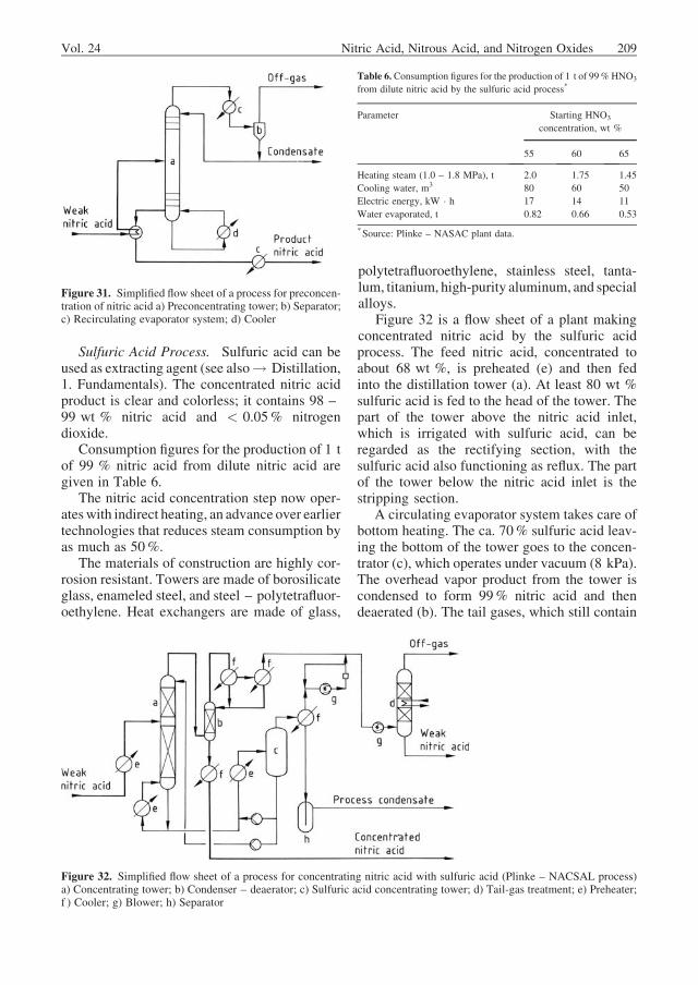
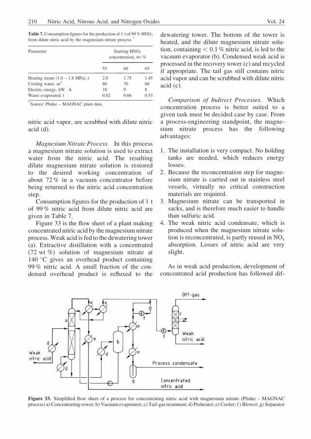
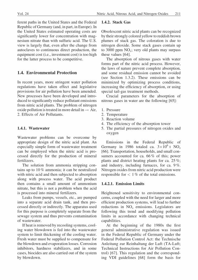
Figure 14 illustrates the steps necessary for im-plementation of the Ostwald process. Industrialprocesses differ in the sequence and design ofthese steps. This section describes processesfor the production of weak acid [61, pp. 61 –98] and strong acid [61, pp. 99 – 130].
1.3.4.1. Weak Acid Processes
The first industrial plants for the production ofweak acid employed atmospheric combustionand low-pressure absorption [3]. This type ofplant is no longer built. It was followed bya process employing atmospheric combustionand absorption at medium pressure. This processhas the advantage of lower absorption costsbecause the marked improvement in absorptionobtained with the pressure generated by a nitrousgas compressor allows the apparatus to be down-sized. The energy of compression can be partiallyrecovered with a tail-gas turbine. To circumventthe difficulty of operating a compressor fornitrous gas and obtain a further decrease in plantvolume, to ammonia was also oxidized at medi-
um pressure. This type of process is particularlyeconomical for smaller capacities and is thusdescribed first.
As plant capacities continued to grow andlower tail-gas levels of NOx were necessary theabsorption pressure was increased still further.Lower energy costs and shorter depreciationperiods in the United States have led to a prefer-ence for the high-pressure process, whereasmorefavorable consumption and production figures inEurope have favored the dual-pressure processwith medium-pressure combustion and high-pressure absorption.
The principle of medium- and high-pressure(monopressure) plants is that air for ammoniaoxidation and NOx absorption is compressed tothe desired pressure. The ‘‘primary’’ air for oxi-dation is then mixed with ammonia and forcedthrough the burner. The ‘‘secondary’’ air forstripping dissolved NOx out of the raw acid andoxidizing the intermediate nitrogen monoxide issupplied upstream of the absorption tower. Thetail gas is heated and then expanded in a turbine(on a common shaft with the compressor) toproducemechanical energy. The remaining drivepower is supplied by a steam turbine running onprocess steam.
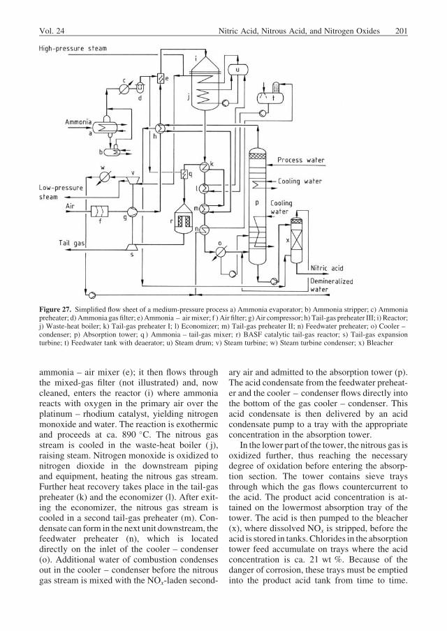
Medium-Pressure Process. Figure 27 isa flow sheet of a medium-pressure process(ca. 550 kPa). Liquid ammonia is evaporated atca. 700 kPa in the ammonia evaporator (a). Thecold generated can be used in the absorptionstep. Water is removed from liquid ammonia inan ammonia stripper (b). The ammonia – waterblowdown mixture is evaporated batchwise withsteam. Residual aqueous ammonia can be used infertilizer production. The ammonia vapor is heat-ed with steam to ca. 90 �C in the ammoniapreheater (c) and then filtered (d). If necessary,a small stream of ammonia is diverted to tail-gastreatment.
All the air needed for the process is sucked inthrough the air filter (f ) by the air compressor (g).The compressed air is divided into two sub-streams in a tail-gas preheater (h). The secondaryair goes to the bleacher (x) for stripping raw acid.The secondary airstream exiting the bleacher isladen with NOx and is added to the nitrous gasbefore it enters the absorption tower ( p). Thegreater part of the process air, the primary air, ismixed with the superheated ammonia in the
200 Nitric Acid, Nitrous Acid, and Nitrogen Oxides Vol. 24
ammonia – air mixer (e); it then flows throughthe mixed-gas filter (not illustrated) and, nowcleaned, enters the reactor (i) where ammoniareacts with oxygen in the primary air over theplatinum – rhodium catalyst, yielding nitrogenmonoxide and water. The reaction is exothermicand proceeds at ca. 890 �C. The nitrous gasstream is cooled in the waste-heat boiler ( j),raising steam. Nitrogen monoxide is oxidized tonitrogen dioxide in the downstream pipingand equipment, heating the nitrous gas stream.Further heat recovery takes place in the tail-gaspreheater (k) and the economizer (l). After exit-ing the economizer, the nitrous gas stream iscooled in a second tail-gas preheater (m). Con-densate can form in the next unit downstream, thefeedwater preheater (n), which is locateddirectly on the inlet of the cooler – condenser(o). Additional water of combustion condensesout in the cooler – condenser before the nitrousgas stream is mixed with the NOx-laden second-
ary air and admitted to the absorption tower (p).The acid condensate from the feedwater preheat-er and the cooler – condenser flows directly intothe bottom of the gas cooler – condenser. Thisacid condensate is then delivered by an acidcondensate pump to a tray with the appropriateconcentration in the absorption tower.
In the lower part of the tower, the nitrous gas isoxidized further, thus reaching the necessarydegree of oxidation before entering the absorp-tion section. The tower contains sieve traysthrough which the gas flows countercurrent tothe acid. The product acid concentration is at-tained on the lowermost absorption tray of thetower. The acid is then pumped to the bleacher(x), where dissolved NOx is stripped, before theacid is stored in tanks. Chlorides in the absorptiontower feed accumulate on trays where the acidconcentration is ca. 21 wt %. Because of thedanger of corrosion, these trays must be emptiedinto the product acid tank from time to time.
Figure 27. Simplified flow sheet of a medium-pressure process a) Ammonia evaporator; b) Ammonia stripper; c) Ammoniapreheater; d) Ammonia gas filter; e) Ammonia – air mixer; f ) Air filter; g) Air compressor; h) Tail-gas preheater III; i) Reactor;j) Waste-heat boiler; k) Tail-gas preheater I; l) Economizer; m) Tail-gas preheater II; n) Feedwater preheater; o) Cooler –condenser; p) Absorption tower; q ) Ammonia – tail-gas mixer; r) BASF catalytic tail-gas reactor; s) Tail-gas expansionturbine; t) Feedwater tank with deaerator; u) Steam drum; v) Steam turbine; w) Steam turbine condenser; x) Bleacher
Vol. 24 Nitric Acid, Nitrous Acid, and Nitrogen Oxides 201
Cooling water flowing through coils on the sievetrays removes heat generated by the oxidation ofnitrogen monoxide to nitrogen dioxide and itsfurther conversion to nitric acid. Part of the heatabsorbed by the cooling water is utilized toevaporate ammonia. A demister in the head ofthe tower collects liquid droplets entrained in thetail gas; the condensate runs back to the last trayof the absorption tower.
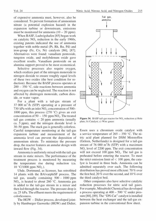
The tail gas absorbs heat from the secondaryair and the nitrous gas in three tail-gas preheaters.In the BASF catalytic tail-gas treatment (r; seealso Section 1.4.2.3), ca. 60 vol% of the NOx inthe tail gas is selectively reacted with ammonia.Hot tail gas containing < 200 ppm NOx goes tothe tail-gas expansion turbine (s), in which me-chanical energy is produced to drive the aircompressor. Finally, the tail gas is discharged tothe atmosphere via the stack.
The tail-gas expansion turbine supplies part ofthe power needed to drive the air compressor. The
rest is generated by a condensing steam turbinesupplied with product steam. The turbine may bebled. The steam turbine condensate goes to theboiler feedwater preheater (n) where it absorbsheat from the NOx gas and then flows through thedeaerator into the feedwater tank (t). Nondeaer-ated feedwater from the battery limit also flowsvia a preheater into the feedwater tank. The boilerfeedwater pump raises the pressure of the deaer-ated feedwater to the requisite boiler pressure.Product steam is raised with heat from ammoniacombustion in the waste-heat boiler ( j).
Most of the steam generated in the waste-heatboiler drives the condensing steam turbine. Theremainder can be utilized in the ammoniapreheater and stripper and for deaerating thefeedwater; any excess is exported as productsteam.
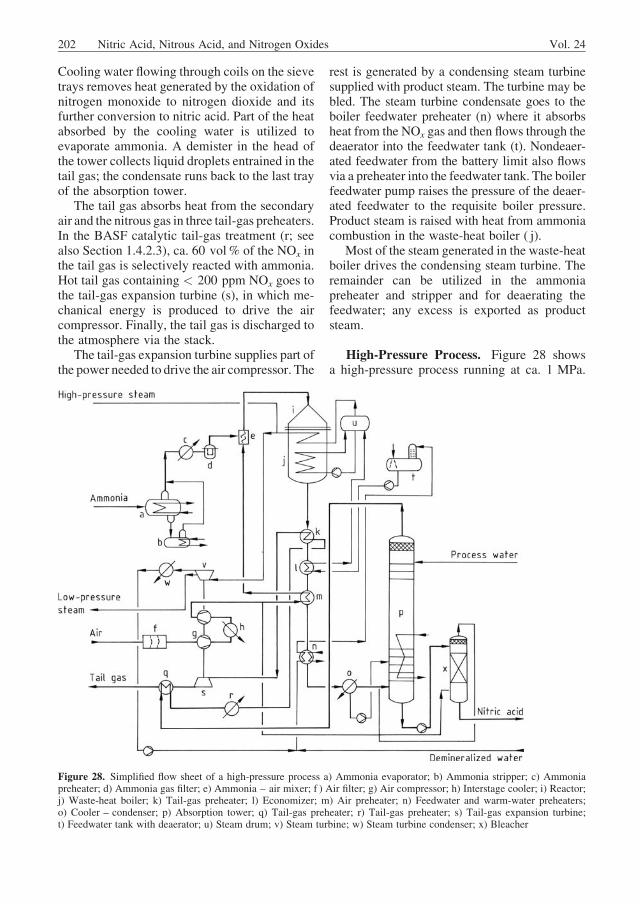
High-Pressure Process. Figure 28 showsa high-pressure process running at ca. 1 MPa.
Figure 28. Simplified flow sheet of a high-pressure process a) Ammonia evaporator; b) Ammonia stripper; c) Ammoniapreheater; d) Ammonia gas filter; e) Ammonia – air mixer; f ) Air filter; g) Air compressor; h) Interstage cooler; i) Reactor;j) Waste-heat boiler; k) Tail-gas preheater; l) Economizer; m) Air preheater; n) Feedwater and warm-water preheaters;o) Cooler – condenser; p) Absorption tower; q) Tail-gas preheater; r) Tail-gas preheater; s) Tail-gas expansion turbine;t) Feedwater tank with deaerator; u) Steam drum; v) Steam turbine; w) Steam turbine condenser; x) Bleacher
202 Nitric Acid, Nitrous Acid, and Nitrogen Oxides Vol. 24
Liquid ammonia is fed into the evaporator (a),where it is evaporated at ca. 1.15 MPa againstwarm water. The evaporation temperature risesslightly above 35 �C as the water content buildsup in the evaporator. The ammonia – waterblowdown mixture is evaporated with low-pres-sure steam in the ammonia stripper (b). Theresidual ammonia concentration is ca. 2.5%.
Ammonia exiting the evaporator system isheated to ca. 130 �C in the ammonia preheater(c), and contaminants are removed in the ammo-nia gas filter (d).
Air is sucked in through the air filter (f) andcompressed to ca. 1 MPa in an air compressor (g)with interstage cooling (h). The primary air(ca. 80% of the total) is heated to ca. 180 �Cagainst nitrous gas in the air heater (m) and thenfed to the ammonia – air mixer (e). The mixedgas stream has a temperature of ca. 175 �C andcontains 10.7 vol% ammonia. It passes througha filter (not illustrated) into the reactor (i) wherethe ammonia and atmospheric oxygen react overthe platinum – rhodium catalyst at ca. 900 �C toform mainly nitrogen monoxide and water.
The reaction gases next pass through thewaste-heat boiler ( j), where they are cooled toca. 400 �C. The heat is used to raise high-pres-sure steam and superheat it to 500 �C in thepreevaporator, superheater, and reevaporator ofthe boiler.
The boiler system is fed with condensate fromthe steam turbine condenser (w) plus deminer-alized water from the battery limit. Both streamsare led to a tank and from there go through thefeedwater preheater (n) to the deaerator mountedon the feedwater tank (t) and operating at a slightgauge pressure. The tank serves as suction vesselfor the feedwater pumps, which deliver waterthrough the economizer into the boiler drum (u).
The water – steam mixture in the evaporatoris circulated by the boiler circulation pump.Saturated steam and water are separated in theboiler drum (u).
After leaving the waste-heat boiler ( j), thenitrous gas is cooled to ca. 260 �C in a tail-gaspreheater (k). After passing through a run ofpiping for oxidation, nitrous gas gives up moreuseful heat in the economizer (l), and its temper-ature falls to ca. 210 �C. After another oxidationrun, the stream is led into the air heater (m) andcooled to ca. 180 �C. The heat recovered is usedto preheat the primary air.
Before the nitrous gas is led into the gascooler – condenser (o), it passes through feed-water preheaters and through the warm-waterheater (n) both mounted on the two inlets of thecooler – condenser. The nitrous gas is cooled toca. 115 �C and partly condensed before enteringthe cooler – condenser.
In the water- cooled cooler – condenser (o),the gas is cooled to< 50 �C so that water formedduring ammonia oxidation condenses to produceca. 45% acid. This product is delivered to theappropriate tray of the absorption tower (p) bythe acid condensate pump. The NOx-ladensecondary air recycled from the bleacher (x) ismixed with the nitrous gas stream before it is fedinto the tower (p).
In the sieve-tray absorption tower (p) thenitrous gas flows countercurrently to the pro-cess water fed at the column head, and nitricacid is formed. Heat from the absorption toweris transferred to the cooling water. Raw acidfrom the absorption tower is treated withsecondary air in the bleacher (x), then deliv-ered to battery limit with the aid of the systempressure.
Tail gas exits the absorption tower at ca. 20–30 �C. It is heated to ca. 80 �C in a tail-gaspreheater (q) against the tail-gas stream from theexpansion turbine. The tail gas is further heatedto 140 �C against low-pressure steam (r) andthen to ca. 375 �C in a tail-gas preheater (k). Itis subsequently expanded in the tail-gas turbine(s); this step produces ca. 70% of the energyrequired to drive the air compressor.
Tail gas exits the turbine at ca. 135 �C and isled to a tail-gas preheater (q), where it is cooled toca. 90 �C before being discharged through thestack.
The rest of the power needed to drive the aircompressor can be supplied by a pass-out con-densing steam turbine (v). The superheatedsteam is delivered to the steam turbine or ex-ported. Part of the steam supplied to the turbine iswithdrawn as low-pressure steam before admis-sion to the condensing section. This low-pressuresteam is used in the plant or exported. The rest ofthe steam supplied to the turbine passes throughthe condensing section and is condensed in thesteam turbine condenser (w).
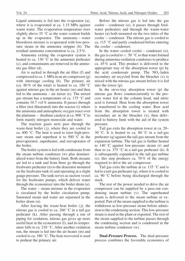
Dual-Pressure Process. The dual-pressureprocess combines the favorable economics of
Vol. 24 Nitric Acid, Nitrous Acid, and Nitrogen Oxides 203
medium-pressure combustion with the effi-ciency of high-pressure absorption. Figure29 is a flow sheet of such a plant with ammo-nia combustion at 0.5 MPa and absorption at1.1 MPa.
Liquid ammonia is fed to the ammoniaevaporator (a), which is under a pressure of ca.0.65 MPa. The entire stream then goes to ammo-nia evaporator I, where ca. 80% of the ammoniais evaporated against cold water at a constanttemperature of ca. 12 �C. Residual liquid ammo-nia is fed to ammonia evaporator II (not illus-trated) and evaporated at varying temperaturesagainst cooling water. The evaporation tempera-ture increases from 12 �C to ca. 20 �C as watercontent builds up in the evaporator. Ammoniaevaporator II is designed so that the entireammonia stream can be evaporated in it, ifnecessary, at a maximum temperature of 20 �C.If the water content or the evaporation tempera-ture in ammonia evaporator II is too high, the
ammonia – watermixture is blown down and fedto the ammonia stripper (b). Ammonia is strippedto a residual content of ca. 2.0% as the tempera-ture is raised to 150 �C with low-pressuresteam. The residue, greatly depleted in ammonia,is discharged.
Gaseous ammonia from the evaporatorsystem is passed through the ammonia gas filter(c) to remove contaminants, then heated to ca.150 �C in the ammonia preheater (d).
Air is sucked through the filter (f) and com-pressed to 0.5 MPa in the compressor (g). About86% of the air is fed as primary air to theammonia – air mixer (e). The mixed gas streamhas a temperature of ca. 220 �C and containsca. 10 vol% ammonia. It is transported throughthe gas-mixture filter (not illustrated) to thereactor (h). Here, ammonia reacts on theplatinum – rhodium catalyst with atmosphericoxygen at 890 �C to produce a 96.5% yield ofnitrogen monoxide and water.
Figure 29. Simplified flow sheet of a dual-pressure process a) Ammonia evaporator; b) Ammonia stripper; c) Ammonia gasfilter; d) Ammonia preheater; e) Ammonia – air mixer; f ) Air filter; g) Air compressor; h) Reactor; i)Waste-heat boiler; j) Tail-gas preheater III; k) Economizer; l) Tail-gas preheater II; m) Feedwater preheater; n) Cooler – condenser I; o) Cooler –condenser II; p) Nitrous gas compressor; q ) Tail-gas preheater I; r) Cooler – condenser III; s) Absorption tower; t) Tail-gasexpansion turbine; u) Feedwater tankwith deaerator; v) Steamdrum;w)Steam turbine; x) Steam turbine condenser; y)Bleacher
204 Nitric Acid, Nitrous Acid, and Nitrogen Oxides Vol. 24
The reaction gases next pass through thewaste-heat boiler (i) and are cooled to 355 �C.The heat is used to raise high-pressure steam inthe preevaporator, superheater, and reevaporatorof the boiler.
The boiler system is fed with condensate fromthe steam turbine condenser (x) plus deminera-lized water from the battery limit. Both streamsare led to a tank and then pass through thefeedwater preheater (m) to the deaeratormountedon the feedwater tank (u). The tank serves asa suction vessel for the feedwater pumps, whichdeliver the water through the economizer (k) intothe steam drum (v).
The water – steam mixture in the evaporatoris circulated by the boiler circulation pump.Saturated steam and water are separated in thesteam drum (v).
After exiting the waste-heat boiler and pass-ing through a run of piping for oxidation, thenitrous gas is cooled from 390 to 280 �C in tail-gas preheater III (j). After further oxidation, itenters the economizer (k), where it is cooledfrom 310 to 200 �C. The nitrous gas gives upfurther useful heat to the tail gas in tail-gaspreheater II (l) and its temperature falls to ca.170 �C.
The gas passes through the feedwater preheat-er (m), mounted on the cooler – condenser inletand thereby cools to ca. 100 �C. In the water-cooled cooler – condenser I (n), the gas is cooledto < 50 �C so that the water formed duringammonia oxidation condenses. A ca. 43 % acidresults and is pumped to the appropriate tray ofthe absorption tower (s). The secondary air ladenwith NOx and recycled from the bleacher (y) isnow mixed with the nitrous gas stream. Themixed stream is then led into cooler – condenserII (o), where it is cooled to ca. 45 �C againstchilled water. More water condenses and a ca.52% acid is formed, which is forwarded forabsorption along with acid formed in cooler –condenser I. The gas is passed through a mistcollector (not illustrated) upstream of the nitrousgas compressor (p).
The nitrous gas is compressed to 1.1 MPa inthe compressor ( p) and has an outlet temperatureof ca. 130 �C. It passes to tail-gas preheater I (q ),where it is cooled to ca. 75 �C. Downstream ofthe preheater is cooler – condenser III (r), whichthe nitrous gas leaves at 50 �C. The resulting acidcondensate has a concentration of ca. 58 wt %
and is mixed with the raw acid from the absorp-tion column.
From cooler – condenser III the nitrous gas,now at least 90% oxidized, enters the absorptiontower (s). The gas first passes through oxidationtrays that receive only a slight flow of liquid, toattain the degree of oxidation needed for equi-librium with 68% acid. In the absorptionsection, gas and liquid move countercurrently.Required process water is pumped to the towerhead. The 68% raw acid is withdrawn fromthe first absorption tray and then treated withsecondary air in the bleacher (y). It is deliveredto the battery limit with the aid of the systempressure.
Approximately 80% of the heat generated byabsorption is transferred to the cooling water andthe remainder to the chilled water employed inthe last part of the absorption step where verylittle heat of reaction is liberated.
The tail gas contains < 150 – 200 ppm NOx
and exits the absorber at 20 �C. It is heated to110, 200, and finally 350 �C in the three down-stream tail-gas preheaters (q, l, and j) beforebeing expanded in the tail-gas turbine (t). Theturbine supplies ca. 67% of the power requiredby the air and the nitrous gas compressors. Theexpanded tail gas has a temperature of ca. 100 �Cand is discharged through a stack.
The remaining power required to drive therotating machinery can be obtained from a pass-out condensing steam turbine (w). Superheatedsteam is fed to the turbine or exported. Part of thesteam supplied to the turbine may be withdrawnas low-pressure steam before it enters the con-densing section. This low-pressure steam maybe used in the plant or exported. The remainder ofthe steam fed to the turbine passes through thecondensing section and is condensed in the steamturbine condenser (x).
Comparison of Medium- and High-Pressure Processes. [62]. Two trends can beseen in the worldwide development of weak acidprocesses. First, from the process-engineeringstandpoint, a progression occurs from low-through medium- to high-pressure processes[5]. Second, capacities continue to increase;single-train plants producing up to 2000 t ofnitric acid per day are now being built. In Europe,the dual-pressure design is preferred for largerplants, whereas smaller ones employ the mono-
Vol. 24 Nitric Acid, Nitrous Acid, and Nitrogen Oxides 205
pressure design. Where feedstock and energyprices are low, monopressure operation offersspecial advantages; low investment costs ensurea quick payout, particularly in North America. If,on the other hand, feedstock and energy pricesare very high (as in Europe), yield and energyefficiency must be maximized, so higher invest-ment costs are acceptable. Table 5 comparesconsumption figures per unit product for mono-pressure and dual-pressure processes.
New pollution control regulations and theenergy crisis of the mid-1970s have also led tothe development of new processes or the im-provement of existing ones. To avoid the needfor catalytic tail-gas treatment in large-tonnageplants (and thus an increase in specific ammoniaconsumption), new facilities employ higherabsorption pressures.
1.3.4.2. Concentrated Acid Processes
Industrially produced nitric acid contains 50 –70 wt %HNO3. This is high enough for fertilizerproduction, but nitration processes in industrialorganic chemistry call for concentrated acid(98 – 100%). Distillation, the simplest way toconcentrate dilute acid, fails because nitric acidand water form an azeotrope (68.4% HNO3 atatmospheric pressure).
Concentrated nitric acid is manufactureddirectly or indirectly [63]. In the direct process,the water generated in ammonia combustion iswithdrawn by rapid cooling to give a nitrous gasmixture from which concentrated acid can beproduced directly in one of two ways. First, thecompletely oxidized NOx can be separated inliquid form by absorption in concentrated nitric
acid and then led to a reactor where it is reactedwith oxygen and water (or weak acid) underpressure to yield concentrated acid. Second,nitrous gases can be reacted with azeotropic acidto form a concentrated acid that can be convertedeasily to concentrated and azeotropic acid bydistillation. The latter product is either complete-ly recycled or used in the production of ordinaryweak acid.
In the indirect processes, concentration isbased on extractive distillation and rectificationwith sulfuric acid or magnesium nitrate.
Direct Process. The essential feature of theclassical direct process (Fig. 30) is that liquiddinitrogen tetroxide is produced and reactedunder pressure with pure oxygen and a certainquantity of dilute nitric acid. A detailed accountof concentrated acid production via azeotropicnitric acid is given in [61, pp. 99 – 130].
Ammonia Oxidation. As in weak acid pro-cesses, feed ammonia is evaporated, superheat-ed, and filtered (see Section 1.3.4.1). Evaporationtakes place with the aid of water heated withprocess heat. Because traces of water and oilaccumulate in the ammonia evaporator the sumpmust be drained into the steam-heated stripperfrom time to time. Air for ammonia combustionis sucked through a filter (a) and mixed withpurified ammonia in themixer ( b). The ammoniacontent of the mixture is held in the range 11.5–12.3 vol%, depending on the temperature. Theoptimal combustion temperature is 830 –850 �C. Ammonia oxidation takes place overconventional platinum – rhodium catalysts inthe reactor (d). The heat of reaction is used to
Table 5. Comparison of significant specific consumption figures for nitric acid plants (values are given per tonne of 100% HNO3, the tail gas
contains < 200 ppm of NOx )
Parameter Monopressure processes Dual-pressure process
* Includes 1 kg NH3 for NOx reduction from 600 to < 200 ppm.** Includes water for steam turbine compressor.
206 Nitric Acid, Nitrous Acid, and Nitrogen Oxides Vol. 24
raise steam in a waste-heat boiler and an econo-mizer. The process gas exits the economizer atca. 170 �C and is then cooled to 25 �C ina cooler – condenser (e), giving an acid contain-ing ca. 2 – 3 wt % nitric acid. The cooler –condenser is specially designed to condense asmuch water as possible without much NOx
absorption. Part of the process heat is also trans-ferred to the warm water used for ammoniaevaporation. The weak condensate generated inthe cooler – condenser is used as scrub liquor forfinal absorption.
Oxidation of NitrogenMonoxide. Secondaryair is mixed with the cooled process gas tooxidize nitrogen monoxide to nitrogen dioxide.The amount of secondary air must be sufficient toensure that the tail gas has a minimal oxygencontent (2.5 – 3.5 vol%) before it is dischargedto the atmosphere. The concentrated nitric acidventing system is connected to the secondary airintake in such a way that oxygen and nitrogenoxides liberated on venting are recycled to theprocess. The nitrogen monoxide gas and second-ary air are compressed together to ca. 0.14MPa(f ). After further cooling (g) to remove the heatof compression, the mixture enters the oxidationtower (h), which is usually equipped with sievetrays. Tube coils on the trays remove the heat ofoxidation. To maintain a liquid level on all trays,
acid from the tower bottom is pumped (recircu-lated) to the head.
Final Oxidation of Nitrogen Monoxide. Thenitrous gases leaving the oxidation towerare approximately 95% oxidized and are led toa final oxidizer ( postoxidizer) (j) where they arecompletely oxidized by desorption of concen-trated nitric acid. The acid moves countercur-rently to the nitrous gases.Water produced in thisreaction dilutes the concentrated acid; acid leav-ing the postoxidizer contains ca. 75% HNO3.Flow control of the concentrated nitric acid feedinto the postoxidizer is important because toohigh a rate lowers the output of concentrated acid,whereas too low a rate displaces final oxidationinto the absorber, with the result that the concen-trated nitric acid entering the absorption tower istoo dilute. The product gas is saturated withnitric acid vapor. For the next step, absorption,the process gas is cooled to �10 �C againstbrine in a cooler ( l). Virtually all the nitrogendioxide is dimerized to dinitrogen tetroxide atthis temperature.
Absorption of Dinitrogen Tetroxide. Thenitrous gases are completely dimerized to dini-trogen tetroxide and, in this condition, are fedinto the absorber (m). The absorber consists offour sections, each packed with ceramic Raschig
Figure 30. Simplified flow sheet of a process for direct production of strong nitric acid with oxygen a) Air Filter;b) Ammonia – air mixer; c) Gas mixture filter; d) Reactor; e) Cooler; f ) Compressor; g) Cooler; h) Oxidation tower;i) Recirculating acid tank; j) Postoxidizer; k) Cooler; l) Cooler; m) Absorption tower; n) Final absorber; o) Raw acid tank;p) Cooler; q ) Precondenser; r) Stirred tank; s) Reactor; t) Bleacher; u) Cooler
Vol. 24 Nitric Acid, Nitrous Acid, and Nitrogen Oxides 207
rings. The dinitrogen tetroxide is absorbed inconcentrated nitric acid that comes from thebleacher and is cooled to ca. �10 �C (k, u). Theacid leaving the absorption tower contains ca.25 – 30 wt % dinitrogen tetroxide and ispumped to the raw acid tank (o).
Final Absorption. The gas exiting the ab-sorption tower is practically free of nitrogendioxide but saturated with nitric acid vapor. Thevapor is removed by scrubbing in the final ab-sorber (n), which consists of two sections. Thescrub liquor (weak nitric acid from the cooler –condenser) is recirculated or used to make up thewater balance in the stirred tank.
Dinitrogen Tetroxide Production. The ladenconcentrated nitric acid is sent from the raw acidtank (o) to the bleacher (t), which consists ofa stripping section and a reboiler. The acid entersthe head of the tower and flows downwardcountercurrently to the nitric acid vapor, whichstrips nitrogen dioxide from the concentratednitric acid. The bleached concentrated acid goesto the reboiler section of the bleacher, where it ispartially evaporated and partially withdrawn asproduct acid. The vapor exiting the bleachercontains ca. 95% nitrogen dioxide and 5% nitricacid. Most of the vapor condenses in a down-stream precondenser (q). Dinitrogen tetroxideis liquefied in the liquefier and fed to a stirredtank (r).
Production of Concentrated Nitric Acid.The formation of concentrated nitric acid in thereactor (s) is described by the following equation:
4 NO2ð�2 N2O4ÞþO2þ2 H2O�4 HNO3
This requires a N2O4 – H2O molar ratio of1 : 1 and a weight ratio of 5.11 : 1. The reactiontime can be considerably shortened if dinitrogentetroxide is present in excess. On the otherhand, an excess of dinitrogen tetroxide lowersthe production rate of the reactor and increasesthe dinitrogen tetroxide recycle rate, resulting inhigher steam consumption for bleaching and agreater cold requirement for dinitrogen tetroxideliquefaction.
The N2O4 – H2O ratio, denoted the R factor,is the most important criterion for monitoringreactor operation. In practice, it fluctuates be-tween 6.5 and 7. A product concentration of
> 98 wt % nitric acid requires a higher R factor.The economically most favorable R factor canbe found only by empirical means; the ratio canbe varied to achieve optimal operating condi-tions. The makeup acid used to maintain thewater balance of the raw acid mixture is takenfrom the bottom of the final absorber (n).
Concentrated nitric acid is formed in thereactor (s) at ca. 5.0 MPa and 60 – 80 �C. Highmechanical strength and corrosion resistanceare needed, but these two requirements cannotbe satisfied by any one material. The reactorthus has a carbon steel jacket to provide me-chanical strength and a pure aluminum innershell to provide corrosion resistance. Unreactedoxygen is supplied to the suction of the nitrousgas blower via the venting system. The con-centrated nitric acid product is led to theraw acid tank (o) and then to the bleacher.The bleached concentrated acid is cooled toþ 30 �C (u). Most of the concentrated nitricacid is returned to the absorption tower andfinal oxidation.
Indirect Processes. Two types of indirectprocess are used to produce concentratednitric acid (i.e., product containing > 97 wt %HNO3 ):
1. Sulfuric acid process2. Magnesium nitrate process
Both concentration techniques are based onextractive distillatfication. Weak acid is firstproduced by a conventional process (Section1.3.4.1), then a third component is added toextract the water so that up to ca. 99%nitric acid can be distilled from the ternarymixture.
The starting product is ordinary commercialnitric acid (ca. 55 – 65% HNO3 ). Weaker acidscan be preconcentrated in a single-stage or mul-tistage process to give ca. 68 wt % nitric acid.Figure 31 illustrates a single-stage apparatus.Preconcentration takes place in a continuouscountercurrent distillation tower (a), which canbe of either the packed or the bubble-tray type.The system includes one or, if appropriate, twopreheaters, a recirculating evaporator system forthe tower bottom, a stripping and rectifyingsection for the tower, an overhead condenser,and a reflux separator (b).
208 Nitric Acid, Nitrous Acid, and Nitrogen Oxides Vol. 24
Sulfuric Acid Process. Sulfuric acid can beused as extracting agent (see also! Distillation,1. Fundamentals). The concentrated nitric acidproduct is clear and colorless; it contains 98 –99 wt % nitric acid and < 0.05% nitrogendioxide.
Consumption figures for the production of 1 tof 99 % nitric acid from dilute nitric acid aregiven in Table 6.
The nitric acid concentration step now oper-ateswith indirect heating, an advance over earliertechnologies that reduces steam consumption byas much as 50%.
The materials of construction are highly cor-rosion resistant. Towers are made of borosilicateglass, enameled steel, and steel – polytetrafluor-oethylene. Heat exchangers are made of glass,
polytetrafluoroethylene, stainless steel, tanta-lum, titanium, high-purity aluminum, and specialalloys.
Figure 32 is a flow sheet of a plant makingconcentrated nitric acid by the sulfuric acidprocess. The feed nitric acid, concentrated toabout 68 wt %, is preheated (e) and then fedinto the distillation tower (a). At least 80 wt %sulfuric acid is fed to the head of the tower. Thepart of the tower above the nitric acid inlet,which is irrigated with sulfuric acid, can beregarded as the rectifying section, with thesulfuric acid also functioning as reflux. The partof the tower below the nitric acid inlet is thestripping section.
A circulating evaporator system takes care ofbottom heating. The ca. 70% sulfuric acid leav-ing the bottom of the tower goes to the concen-trator (c), which operates under vacuum (8 kPa).The overhead vapor product from the tower iscondensed to form 99% nitric acid and thendeaerated (b). The tail gases, which still contain
Figure 31. Simplified flow sheet of a process for preconcen-tration of nitric acid a) Preconcentrating tower; b) Separator;c) Recirculating evaporator system; d) Cooler
Table 6. Consumption figures for the production of 1 t of 99%HNO3
from dilute nitric acid by the sulfuric acid process*
Parameter Starting HNO3
concentration, wt %
55 60 65
Heating steam (1.0 – 1.8 MPa), t 2.0 1.75 1.45
Cooling water, m3 80 60 50
Electric energy, kW � h 17 14 11
Water evaporated, t 0.82 0.66 0.53
*Source: Plinke – NASAC plant data.
Figure 32. Simplified flow sheet of a process for concentrating nitric acid with sulfuric acid (Plinke – NACSAL process)a) Concentrating tower; b) Condenser – deaerator; c) Sulfuric acid concentrating tower; d) Tail-gas treatment; e) Preheater;f ) Cooler; g) Blower; h) Separator
Vol. 24 Nitric Acid, Nitrous Acid, and Nitrogen Oxides 209
nitric acid vapor, are scrubbed with dilute nitricacid (d).
Magnesium Nitrate Process. In this processa magnesium nitrate solution is used to extractwater from the nitric acid. The resultingdilute magnesium nitrate solution is restoredto the desired working concentration ofabout 72% in a vacuum concentrator beforebeing returned to the nitric acid concentrationstep.
Consumption figures for the production of 1 tof 99% nitric acid from dilute nitric acid aregiven in Table 7.
Figure 33 is the flow sheet of a plant makingconcentrated nitric acid by themagnesiumnitrateprocess.Weak acid is fed to the dewatering tower(a). Extractive distillation with a concentrated(72 wt %) solution of magnesium nitrate at140 �C gives an overhead product containing99% nitric acid. A small fraction of the con-densed overhead product is refluxed to the
dewatering tower. The bottom of the tower isheated, and the dilute magnesium nitrate solu-tion, containing < 0.1% nitric acid, is led to thevacuum evaporator (b). Condensed weak acid isprocessed in the recovery tower (c) and recycledif appropriate. The tail gas still contains nitricacid vapor and can be scrubbed with dilute nitricacid (c).
Comparison of Indirect Processes. Whichconcentration process is better suited to agiven task must be decided case by case. Froma process-engineering standpoint, the magne-sium nitrate process has the followingadvantages:
1. The installation is very compact. No holdingtanks are needed, which reduces energylosses.
2. Because the reconcentration step for magne-sium nitrate is carried out in stainless steelvessels, virtually no critical constructionmaterials are required.
3. Magnesium nitrate can be transported insacks, and is therefore much easier to handlethan sulfuric acid.
4. The weak nitric acid condensate, which isproduced when the magnesium nitrate solu-tion is reconcentrated, is partly reused in NOx
absorption. Losses of nitric acid are veryslight.
As in weak acid production, development ofconcentrated acid production has followed dif-
Table 7. Consumption figures for the production of 1 t of 99%HNO3
from dilute nitric acid by the magnesium nitrate process *
Parameter Starting HNO3
concentration, wt %
55 60 65
Heating steam (1.0 – 1.8 MPa), t 2.0 1.75 1.45
Cooling water, m3 80 70 60
Electric energy, kW � h 10 9 8
Water evaporated, t 0.82 0.66 0.53
*Source: Plinke – MAGNAC plant data.
Figure 33. Simplified flow sheet of a process for concentrating nitric acid with magnesium nitrate (Plinke – MAGNACprocess) a) Concentrating tower; b) Vacuum evaporator; c) Tail-gas treatment; d) Preheater; e) Cooler; f ) Blower; g) Separator
210 Nitric Acid, Nitrous Acid, and Nitrogen Oxides Vol. 24
ferent paths in the United States and the FederalRepublic of Germany (and, in part, in Europe). Inthe United States estimated operating costs aresignificantly lower for concentration with mag-nesium nitrate than with sulfuric acid. The U.S.view is largely that, even after the change fromautoclaves to continuous direct production, theequipment cost (i.e., investment cost) is too highfor the latter process to be competitive.
1.4. Environmental Protection
In recent years, more stringent water pollutionregulations have taken effect and legislativeprovisions for air pollution have been amended.New processes have been developed and intro-duced to significantly reduce pollutant emissionsfrom nitric acid plants. The problem of nitrogenoxide pollution is treated inmore detail in! Air,2. Effects of Air Pollutants.
1.4.1. Wastewater
Wastewater problems can be overcome byappropriate design of the nitric acid plant. Anespecially simple form of wastewater treatmentcan be employed when the nitric acid is pro-cessed directly for the production of mineralfertilizers.
The solution from ammonia stripping con-tains up to 10% ammonia; it can be neutralizedwith nitric acid and then subjected to absorptionalong with process water. The acid productthen contains a small amount of ammoniumnitrate, but this is not a problem when the acidis processed into mineral fertilizers.
Leaks from pumps, vessels, etc., are pumpedinto a separate acid drain tank, and then pro-cessed directly or indirectly. The apparatus usedfor this purpose is completely separate from thesewage system and thus prevents contaminationof wastewater.
If heat is removed by recooling systems, cool-ing water blowdown is fed into the wastewatersystem to limit thickening of the cooling water.Fresh water must be supplied to compensate forthe blowdown and evaporation losses. Corrosioninhibitors, hardness stabilizers, and in somecases, biocides are also carried out of the systemby blowdown.
1.4.2. Stack Gas
Obsolescent nitric acid plants can be recognizedby their strongly colored yellow to reddish brownplumes of stack gas. The coloration is due tonitrogen dioxide. Some stack gases contain upto 3000 ppm NOx; very old plants may surpassthese values [64].
The absorption of nitrous gases with waterforms part of the nitric acid process. However,the laws of nature prevent complete absorption,and some residual emission cannot be avoided(see Section 1.3.2). These emissions can beminimized by optimizing process conditions,increasing the efficiency of absorption, or usingspecial tail-gas treatment methods.
Crucial parameters for the absorption ofnitrous gases in water are the following [65]:
1. Pressure2. Temperature3. Reaction volume4. The efficiency of the absorption tower5. The partial pressures of nitrogen oxides and
oxygen
Emissions in the Federal Republic ofGermany in 1986 totaled ca. 3�106 t NOx
[66]. Transportation, households, and small con-sumers accounted for ca. 66% of this; powerplants and district heating plants for ca. 25%;and industry, including furnaces, for ca. 9%.Nitrogen oxides from nitric acid production wereresponsible for < 1% of the total emissions.
1.4.2.1. Emission Limits
Heightened sensitivity to environmental con-cerns, coupled with the need for larger and moreefficient production systems, will lead to furtherreductions in NOx emissions. Legislators arefollowing this trend and modifying pollutionlimits in accordance with changing technicalcapabilities.
At the beginning of the 1980s the firstgeneral administrative regulation was issuedin the Federal Republic of Germany under theFederal Pollution Control Act: the TechnischeAnleitung zur Reinhaltung der Luft (TA-Luft;Technical Instructions for Air Pollution Con-trol) [67]. This regulation and the correspond-ing VDI guidelines [68] form the basis for
Vol. 24 Nitric Acid, Nitrous Acid, and Nitrogen Oxides 211
issuing operating permits. Regulations inmany other countries are based on theseguidelines.
The designation NOx is commonly used tospecify emission and concentration valuesbecause stack gases always include mixtures ofnitrogen oxides. For the purpose of standardiza-tion, the oxides are calculated in terms of nitro-gen dioxide. The acceptable concentrations fromTA-Luft 1986 [67] are
1. Mass of substances emitted as mass concen-tration in units of g/m3 or mg/m3, referred tothe volume of stack gas at standard conditions(0 �C, 101.3 kPa) after deducting the mois-ture content of water vapor, or to the volumeof stack gas at standard conditions (0 �C,101.3 kPA) before deducting the moisturecontent of water vapor; and
2. Mass of substances emitted, referred to time,as mass velocity in units of kg/h, g/h, or mg/h;and
3. Ratio of the mass of substances emitted to themass of products generated or processed(emission factors), as mass ratio in units ofkg/t or g/t.
The usual concentration unit ppm (mL/m3 )can be converted to the prescribed mass concen-tration (mg/m3 ) with the following factor [69]:1 ppm ¼ 1.88 mg/m3 (based on monomericNO2 at 101.3 kPa and 298 K and ideal-gasbehavior).
The TA-Luft [67] states that the emission ofnitrogen monoxide and nitrogen dioxide in thestack gas of nitric acid plants must not exceed0.45 g/m3 as nitrogen dioxide. Furthermore,stack gases may be discharged only if colorless;as a rule, this is the case if the mass concentra-tion of nitrogen dioxide in the stack gas doesnot exceed the value given by the followingformula:
Mass concentration of nitrogen dioxide ðmg=m3Þ¼ 1200
Internal diameter of stack orifice ðdmÞ
The requirement of a colorless discharge setsa practical limit of < 200 ppm NOx. Older low-and medium-pressure plants should comply withthese standards by March 1, 1996.
exceeds a rate of 30 kg/h must be equippedwith devices that continuously measure the massconcentration of nitrogen oxides. Quantitativerelationships between emission and ground-levelconcentration are also described, thus settingguidelines for stack design.
If ground-level concentration limits are ex-ceeded, the TA-Luft emission limits are furtherreduced by the relevant authorities. The ground-level concentration limits for gaseous pollutantsin air are as follows [67]: nitrogen dioxide, long-term exposure (IW1), 0.08 mg/m3; short-termexposure (IW2), 0.2 mg/m3.
1.4.2.2. Analysis
The guidelines for the measurement andmonitoring of NOx emissions from nitric acidproduction are specified in [67], [70], [71].
Photometry without auxiliary chemicalreaction and chemiluminescence [71c – e] aresuitable for the continuous measurement of NOx
emissions [65].Difficulties in gas sample preparation due to
condensation are discussed in [71c – g].Additonal apparatus-related problems occurwhen chemiluminescence is used to measureemission of moist stack gases at higher NOx
levels. A chemiluminescence analyzer with amaximum range of 0 – 10 000 ppm has beendeveloped [72].
For stack gases containing traces of ammo-nia, precipitation of ammonium salts in themeasuring cells has prevented continuousmeasurements. Two methods useful for thediscontinuous measurement of nitrogen oxideemissions [65] are acidimetric titration and thephotometric phenoldisulfonic acid technique[71a, b].
1.4.2.3. Control of NOx Emissions
Four basic approaches are used to reduce tail-gasNOx levels: improved absorption, chemicalscrubbing, adsorption, and catalytic tail-gasreduction. Recent decades have seen intenseresearch and development effort invested in thesemethods. More stringent environmental restric-tions have lent special urgency to development inthis area. The most important techniques arecovered in this section.
212 Nitric Acid, Nitrous Acid, and Nitrogen Oxides Vol. 24
Improved Absorption. Absorption effi-ciency depends chiefly on the absorption pres-sure, the number of stages, and the temperature.The temperature of the gas between stages isespecially important because it governs the prog-ress of oxidation, which is the limiting quantityfor the entire absorption process (see Section1.3.2). In an already existing nitric acid plant,the options are to expand the absorption volumeand/or lower the absorption temperature. In thefirst approach, large additional volumes onlyresult in small reductions of tail-gas NOx levelsbecause the oxidation of nitrogen monoxideto nitrogen dioxide proceeds very slowlywhen the NOx concentration is low. The draw-back to this method is that added absorptionvolume in stainless steel is very expensive. Theadvantage is that it does not require any newtechnology. The absorption volume is added inthe form of a second tower; new absorptiontower designs with very few stages have beendevised [73].
The use of cold energy in the absorptionprocess greatly accelerates oxidation of nitrogenmonoxide to nitrogen dioxide. The disadvantageof this method is that the necessary refrigerationequipment and piping demand further invest-ment. Another technique involving the use ofcold to lower the NOx level is to cool the nitrousgas so that more dinitrogen tetroxide than nitro-gen dioxide is formed. The dinitrogen tetroxide isthen scrubbed with nitric acid at ca. 0 �C; it canbe stripped out, and converted to nitric acid by thereaction
N2O4þ1=2 O2þH2O!2 HNO3
in an absorption reactor at ca. 60 – 80 �C. Thetechnique is similar to that in concentrated nitricacid production. The method is, however, moresuitable for investment in a plant being designedthan for the expansion or upgrading of an existingplant.
Chemical Scrubbing. A number of patentsand scientific publications deal with options forscrubbing NOx out of tail gas. Problems relatedto the scrub liquor (cost, regeneration, quantity,and environmental impact) are encountered inall methods. These problems are always easierto manage if the nitric acid plant is part of anintegrated chemical plant, which is usually thecase. However, in some instances a nitric acid
plant or sections of a fertilizer complex mustoperate independently. The following scrubliquors have been proposed: aqueous suspensionof magnesium carbonate and magnesium hy-droxide [74]; solution of vanadium in nitric acid[75]; ammonium sulfide and bisulfide [76]; milkof lime [77]; ammonia [78]; hydrogen peroxide[79]; and urea [80].
Ammonia Scrubbing is used in the UnitedStates. Goodpasture (Texas) has developed a safeprocess based on scrubbing the tail gas withammonium nitrate solution; nitrite formation issuppressed by aeration and the presence of freeacid. The tail gas is then led through an ammo-niacal scrub liquor, pH 7.5 – 8.5. The scrubbingproduct is a 30 – 50% ammonium nitrate solu-tion. The tail gas has a residual level of ca.200 ppm NOx.
Hydrogen Peroxide Scrubbing is based onthe following overall reactions:
NOþNO2þ2 H2O2!2 HNO3þH2O
2 NO2þH2O2!2 HNO3
The reactions are carried on sieve trays or inpacked towers with recirculation of the hydrogenperoxide solution. The advantage of this scrub-bing process is that the reaction time is very fast;the disadvantage, that the hydrogen peroxidescrub liquor is expensive.
A solution containing 20%urea and 10% freenitric acid has also been suggested for scrubbingtail gas to remove NOx. The process is carried atca. 50 �C. Both nitrogen oxides are selectivelyreduced to nitrogen by urea, which decomposesto yield nitrogen and carbon dioxide. The pro-cess, developed by Norsk Hydro in Norway, hasthe advantage that urea is readily available andrelatively cheap. The resulting stack gas plume iscolorless but heavily laden with water vapor.
Adsorption Processes. The adsorption ofNOx by molecular sieves has long been knownbut has not yet been tested intensively in full-scale nitric acid plants.
The Pura-Siv-N process (Union Carbide) isclaimed to reduce stack gas levels below 50 ppmnitrogen dioxide [81], but high investment costsandotherproblemshaveprevented its adoption.Apatent granted to Kernforschungsanlage J€ulichGmbH has a similar object [82], but again indus-
Vol. 24 Nitric Acid, Nitrous Acid, and Nitrogen Oxides 213
trial experience is slight. A ‘‘wet’’ adsorptionsystem has also been developed by Cofaz(France). A carbon- containing adsorbent issprayedwithwaterordilutenitricacidandbroughtin contact with the tail gas. This process has beeninstalled in three monopressure plants [83].
Catalytic Reduction. Catalytic reductionwas the first method used to reduce NOx emis-sions; as early as 1924, a patent for such a processwas issued to FAUSER [84]. A fuel is added, at alevel below the flash point, to the nitrogen oxideswhich then react on the catalyst surface to formnitrogen and water vapor. Most fuels (e.g.,hydrocarbons and hydrogen), however, reactpreferentially with the free oxygen that is alwayspresent in tail gases from nitric acid production.As a result, the nitrogen oxides are not destroyeduntil free oxygen has been consumed. Underthese conditions the reactions with methane canbe described as
CH4þ2 O2!CO2þ2 H2O
CH4þ4 NO!CO2þ2 H2Oþ2 N2
CH4þ2 NO2!CO2þ2 H2OþN2
Ammonia can also be used as a reducingagent, preferentially reducing the nitrogenoxides:
6 NOþ4 NH3!5 N2þ6 H2O
6 NO2þ8 NH3!7 N2þ12 H2O
NOþNO2þ2 NH3!2 N2þ3 H2O
4 NOþO2þ4 NH3!4 N2þ6 H2O
Catalytic reduction processes are accordinglyclassified as nonselective or selective.
Catalysts for nonselective reduction process-es are usually based on platinum, vanadiumpentoxide, iron oxide, or titanium. The fuel re-quirement is the stoichiometric amount neededto reduce all the oxygen present (free and innitrogen oxides) plus a small excess (ca.0.5 vol% CH4 ).
Unfortunately, the principal byproducts ofthis process are carbon monoxide (� 1000 ppm)and hydrogen cyanide. When hydrocarbon fuelsare used, the tail gas must be preheated beforethe reaction on the catalyst proceeds at all. The
preheat temperature depends directly on the fuelselected:
The use of hydrogen allows the preheat tem-perature to be lowered to 150 – 200 �C but isgenerally too expensive.
If the quantity of fuel is not enough to reduceall the oxygen, nitrogen dioxide is reduced onlyto nitrogen monoxide. The stack gas is thendecolorized; in some countries, this is sufficient.Complete NOx removal generally requirespreheating, multiple fixed-bed catalysts (withcooling between beds to prevent overheating),and careful heat recovery to offset part of the fuelcost.
Most nitric acid plants constructed or modi-fied byWeatherly use nonselective catalytic NOx
abatement units with tail-gas exit temperaturesof 650 – 675 �C. Some plants have gas exittemperatures> 815 �C, which is higher than themaximum for admission to the tail-gas expansionturbines. The tail gas must then be cooled, eitheragainst tail gas entering the catalytic unit or withthe aid of waste-heat boilers.
In the processmarketed byDuPont the tail gasis dried, preheated, and then heated in two stages.The gas is subsequently divided into two streams.One substream is heated further, mixed withmethane, and led over the first fixed-bed catalyst.The second substream is mixed with methanewithout further heating and led over the secondfixed-bed catalyst, along with the first substream.Hot tail gases exit the bottom of the reactorand are led through the tail-gas expansionturbine, which recovers part of the work ofcompression.
Ammonia is the only economically relevantreducing agent for selective catalytic processes.The consumption of reducing agent in the selec-tive treatment of NOx is much smaller than innonselective processes. Furthermore, the tail-gastemperature after reduction is significantly low-er, allowing the use of simpler, cheaper construc-tion materials. The optimal catalyst servicetemperature is 250 – 350 �C, but operation atup to 500 �C is possible. The costs due to the use
214 Nitric Acid, Nitrous Acid, and Nitrogen Oxides Vol. 24
of expensive ammonia must, however, also beconsidered. To prevent formation of ammoniumnitrate (a potential explosion hazard) in theexpansion turbine or downstream, emissionsmust be monitored for ammonia (10 – 20 ppm).
When BASF, Ludwigshafen [85] began workon catalytic NOx reduction in the early 1960s,existing patents indicated the use of ammoniatogether with noble-metal (Pt, Rh, Ru, Pd) andiron-group (Fe, Co, Ni) catalysts [86], [87].Alternatives were found: vanadium pentoxide,tungsten oxide, and molybdenum oxide gaveexcellent results. Vanadium pentoxide on analumina support proved to be most economical.
Selective processes also require oxygen,which oxidizes part of the nitrogen monoxide tonitrogen dioxide to ensure roughly equal levelsof these two oxides (the best condition for re-duction). Because the BASF process operates at200 – 350 �C, side reactions between ammoniaand oxygen can be neglected. The reaction is notaffected by dinitrogen monoxide, carbon diox-ide, or water vapor.
For a plant with a tail-gas stream of37 000 m3 /h (STP) operating at a pressure of730 kPa with an inlet NOx concentration of 500–1000 ppm, this process (270 �C) gives an exitconcentration of 50 – 150 ppmNOx. The treatedtail gas contains < 20 ppm ammonia (usuallyca. 5 ppm), and the nitrogen dioxide level is30–50 ppm. The stack gas is generally colorless.Careful temperature monitoring at the tail-gasexpansion turbine and measurement of theammonia level can prevent the deposition ofammonium nitrate. To minimize the pressuredrop, the reactor features an annular design withinward flow (Fig. 34).
Ammonia is uniformlymixedwith the tail-gasstream in static mixers. The performance of thetreatment process is monitored by measuringthe temperature rise during reduction (ca.10 �C/1000 ppm NOx ).
Uhde, Dortmund, as licensee, has retrofitted14 plants with the BA\varphiSF process. Thetail gas, usually containing 500 – 1000 ppmNOx, is heated to about 260 �C. Ammonia gasis added to the tail-gas stream in a mixer andthen led through the reactor. The pressure drop isca. 25 kPa. The effluentmeets the requirement ofcolorlessness.
The HGW – Didier process, developed joint-ly by Hamburger Gaswerke (HGW) and Didier,
Essen uses a chromium oxide catalyst witha service temperature of 265 – 350 �C. The ni-tric acid plant planned for DSM Miststoffen(Geleen, Netherlands) is designed for a tail-gasstream of 76 000 m3/h (STP) with a maximumNOx level of 2200 ppm. The exit concentrationwill not exceed 100 ppm NOx. The tail gas ispreheated before entering the reactor. To meetthe strict emission limit of< 100 ppm, the cata-lyst is located in three beds. Ammonia can beadmitted separately over each. The followingdistribution has proved most efficient: 70% overthe first bed, 20% over the second, and 10%overthe third catalyst bed.
Other companies also have selective catalyticreduction processes for nitric acid tail gases.For example,Mitsubishi Chemical has developeda process operating at 400 – 500 �C under pres-sure [88], [89]. The ‘‘DN-Cat’’ catalyst is installedbetween the heat exchanger and the tail-gas ex-pansion turbine in the conventional flow sheet.
Figure 34. BASF tail-gas reactor for NOx reduction a) Holeplate; b) Catalyst; c) Wire gauze
Vol. 24 Nitric Acid, Nitrous Acid, and Nitrogen Oxides 215
The Weatherly selective catalytic processoperates at 250 – 310 �C. The noble-metalcatalysts are the same ones employed in nonse-lective processes, except that the fuel is replacedby ammonia.
The Bergbauforschung – Uhde process [90]is chiefly employed for stack-gas cleanup atpower plants but may later find use in emissionabatement at nitric acid plants. The Bergbau-forschung – Uhde process for simultaneoussulfur and NOx removal from stack gases isutilized at the cold end of the power-plantboiler, i.e., downstream of the air preheaterand electrostatic filter. It employs the adsorp-tive and catalytic properties of ‘‘activatedcoke’’ at 50 – 150 �C. The reducing agent isagain gaseous ammonia. The technique com-bines a selective catalytic process for NOx andan adsorptive one for sulfur dioxide. Thecatalyst is therefore installed in a moving-bedreactor.
1.5. Storage and Transportation
As a rule, nitric acid is stored in stainlesssteel tanks and transported in stainless steelcontainers.
The regulations for transport by rail [91], [92]and road [93], [94] differentiate among > 70%nitric acid, 55 – 70% nitric acid, and < 55%nitric acid, and also between mixtures with sul-furic acid (‘‘mixed acid’’) containing > 30%nitric acid and those containing < 30% nitricacid. Similar regulations [95] apply to transportby ship. Important transport regulations for> 70% nitric are as follows:
IMDG Code Class 8, D 8261, E – F 8186
UN No. 2032
RID/ADR Class 8, no. 2 a
CFR 49: 172.101, Cor. M
Regulations for < 70% nitric acid are
IMDG Code Class 8, D 8260, E – F 8185
UN No. 2031
RID/ADR Class 8, no. 2 b
CFR 49: 172.101, Cor. M
Provisions range from details of technicalequipment to labeling and give instructions in
case of accidents. Regulations for the roadtransport of nitric acid (� 70% HNO3 empha-size the associated hazards ( poisoning byinhalation of vapors, danger of chemical burnson contact with flammable substances, forma-tion of nitrous gases). Protective equipmentincludes respiratory protection apparatus, gog-gles, and clothing affording complete cover-age, as well as an eyewash bottle with purewater. In case of accident, the fire and policedepartments are to be notified immediately.Spilled nitric acid must not be absorbedwith sawdust or other flammable material (be-cause of the fire hazard); instead, its spreadmust be prevented by the construction of earthbarriers.
1.6. Uses and Economic Aspects
The principal use of nitric acid is as a startingmaterial in the manufacture of nitrogen ferti-lizers; large amounts are reacted with ammo-nia to yield ammonium nitrate (! AmmoniumCompounds, Section 1.2.1.). Weak acid(ca. 60% HNO3 ) is most suitable for thispurpose. Smaller amounts of weak acid areused to digest crude phosphates. About 75 –85% of the nitric acid produced is used in thefertilizer sector. In addition, porous ammoni-um nitrate prills are still an important compo-nent of explosives (! Explosives, Section7.2.).
Nitric acid is used as a nitrating agent in thepreparation of explosives (! Explosives) andorganic intermediates such as nitroalkanes (!Nitro Compounds, Aliphatic) and nitroaromatics(! Nitro Compounds, Aromatic). It is also usedin the production of adipic acid (! Adipic Acid,Section 4.1.).
Other applications include use as a chemicalin metallurgy (e.g., as an etchant and picklingagent for stainless steels) and in rocket fuelproduction.
Worldwide output of nitric acid in 1987was 26.882�106 t, representing a slight in-crease of ca. 4% over 1976. Production inindustrialized countries has stagnated or evendeclined, but in 1976 – 1985 increases in ca-pacity in less industrialized countries occurred[96]. Production figures for nitric acid in 1987follow (106 t):
216 Nitric Acid, Nitrous Acid, and Nitrogen Oxides Vol. 24
Europe, total 16.472
United States 6.553
Eastern Europe 4.289
Asia 1.544
Federal Republic of Germany 2.112
Poland 2.136
Belgium 1.470
Spain (1986) 1.249
Italy 1.195
Hungary 1.018
2. Nitrous Acid
Nitrous acid [7782-77-6], HNO2, Mr 47.01, is amoderately strong to weak acid. Its dissociationconstant K in highly dilute solutions at 18 �C is4.5�10�4. The acid is stable only in cold diluteaqueous solution. It can be prepared as follows:
BaðNO2Þ2þH2SO4!2 HNO2þBaSO4
On heating in the presence of sand, glasssplinters, or other sharp-edged objects, or evenat low temperature, it disproportionates as
3 HNO2�HNO3þ2 NOþH2O
This disproportionation reaction influencesthe properties of nitrous acid solutions and isimportant in the production of nitric acid. Nitrousacid occurs as an intermediate productwhenNOx
gases are absorbed in water.Byvirtueof the above reaction, nitrous acidcan
act as both a reducing and an oxidizing agent.Strong oxidizing agents such as potassium per-manganateoxidizenitrousacid tonitricacid. It canbe reduced to less oxygen-rich compounds (NO2,NO, H2N2O2, NH3 ) by alkali amalgams or byelectrolyticmeans. Its salts (nitrites) are not stablein aqueous solution because of hydrolysis.
Nitrous acid in aqueous solutions is assumedto be in dynamic equilibrium with its anhydride:
2 HNO2�N2O3þH2O
Aqueous solutions of the acid appear colorlessbut take on an increasingly blue coloration at 5%dinitrogen trioxide.
Figure 35 shows the phase diagram of theN2O3 – H2O system with its sizable miscibilitygap. Mixtures break up into a lighter layer with ahigh water content and a heavy layer with a highdinitrogen trioxide content.
Nitrous acid exists in two isomeric forms:
These structures lead to two series of indus-trially important organic derivatives:
An especially important property of nitrousacid is itsability todiazotizeorganicamines.Withprimary amines, the acid forms diazonium salts:
R�NH2þHNO2þHCl!½R�N NClþ2 H2O
These salts are usedwidely in themanufactureof azo dyes (! Azo Dyes, 1. General).
With secondary amines, nitrosamines areformed:
Figure 35. The systemN2O3 – H2O a) Ice; b) Homogeneousliquid, water þ dinitrogen trioxide; c) Liquid phase, twolayers; d) Homogeneous liquid, dinitrogen trioxide þ water
Vol. 24 Nitric Acid, Nitrous Acid, and Nitrogen Oxides 217
R2�NHþHNO2!R2�N�NOþH2O
Ammonia and urea react with nitrous acid toyield nitrogen:
NH3þHNO2!N2þ2 H2O
3. Nitrogen Oxides
Compounds of oxygen with nitrogen are consid-ered as a class and called nitrogen oxides (oftendenoted as NOx ).
The known oxides and their equilibrium reac-tions are as follows:
Very little is known about nitrogen trioxide(NO3 ) or its dimeric form (N2O6 ).
The compounds listed above are described inmore detail in order of their oxidation state. Table 8lists their most important physical properties.
3.1. Dinitrogen Monoxide
Properties (see Table 8). Under normal con-ditions (i.e., room temperature and atmosphericpressure), dinitrogen monoxide [10024-97-2], al-so called nitrous oxide, N2O, Mr 44.01, is acolorless gas with a weak, pleasant odor and asweetish taste. If inhaled, it can bring about aspasmodic inclination to laugh and a conditionresembling drunkenness—hence, its historicname, laughing gas [97]. Two mesomeric formsin resonancewith each other describe the electrondistribution in the molecule [7]:
Production. Dinitrogen monoxide occursas a byproduct of denitrification (especially inthe heavy use of nitrogen fertilizers) and, to someextent, in the nitrification of nitrationwaste acids.The compound was first prepared by PRIESTLEY,who carefully heated ammonium nitrate:
NH4NO3!N2Oþ2 H2O
This is still a common route for industrialproduction.
218 Nitric Acid, Nitrous Acid, and Nitrogen Oxides Vol. 24
In earlier processes [98], high-purity ammo-nium nitrate was used (contamination by organicmaterial and chlorides had to be avoided), andtemperatures up to 260 �C were reached. Today,in contrast, ammonium nitrate can be decom-posed in aqueous solution containing chloridesand nitric acid at temperatures as low as 100 –160 �C. This synthesis was introduced in 1970by Hoechst [99] (Fig. 36)
The decompositon flask (a) is supplied withgaseous ammonia and nitric acid (30 – 100%).Ammonia gas forms the atmosphere for the entiresystem, including the tower (b). A small amountof chloride ion (> 0.2%) is maintained in theaqueous nitric acid solution in the decompositionflask (a) to accelerate the reaction. If appropriate,catalytically useful amounts of metal ions (man-ganese, copper, cerium, lead, bismuth, cobalt, ornickel) may also be added. Heat liberated duringthe reaction raises the temperature to 100 –160 �C. The solution contains 15 – 35% nitricacid, 30 – 50% ammonium nitrate, 15 – 55%
water, and 0.01 – 0.1% chloride ion. The impureproduct dinitrogen monoxide ascends from thedecomposition flask (a) into the tower (b). Am-monia in the gas space neutralizes any entrainedacidic constituents, and this reaction heats thelower part of the tower (b). The hot gas is cooledand scrubbed by an aqueous ammonium nitratesolution fed through a distributor (c). The solu-tion collected in the bottom of the tower (b) hasa temperature of 50 – 110 �C; most of it isrecycled through the heat exchanger (d). Thethermal energy recovered serves to heat theevaporator (e), which concentrates a small partof the solution stream for recycling to the de-composition flask (a). If the temperature profilein the system is not too low, the process does notneed a heat supply.
This process has two main advantages overearlier ones: it offers a substantial energy savingand produces dinitrogen monoxide free of harm-ful byproducts.
The dinitrogen monoxide can easily by lique-fied under pressure and is available in steel cy-linders. Transport regulations for dinitrogenmonoxide (compressed) are as follows:
IMDG Code Class 2.2
UN No. 1070
RID/ADR Class 2, no. 5 a
CFR 49: 172.102 Nonfla. G
Uses. The principal uses of dinitrogen mon-oxide are as follows:
1. In medicine, as an anesthetic2. In the munitions – explosives industry, as
a propellant3. In the food industry, as a foaming agent
(whipped cream)
Production data for dinitrogen monoxide aregiven in [100].
3.2. Nitrogen Monoxide
Nitrogen monoxide [10102-43-9], also callednitric oxide, NO, Mr 30.01, is a colorless, toxic,nonflammable gas at room temperature. As soonas it comes in contact with atmospheric oxygen,it is oxidized to nitrogen dioxide, a brown vapor.For physical properties, see Table 8.
Figure 36. Industrial production of dinitrogen monoxide[99] a) Decomposition flask; b) Scrubbing tower; c) Ammo-nium nitrate distributor; d) Heat exchanger; e) Evaporator
Vol. 24 Nitric Acid, Nitrous Acid, and Nitrogen Oxides 219
Nitrogen monoxide is at dynamic equilibriumwith its dimer:
2 NO�N2O2 DH ¼ �10:5 kJ=mol
At high temperature, however, the equilibri-um is shifted all the way toward nitrogen mon-oxide. Liquid nitrogen monoxide is completelydimerized, probably as angular ONNO mole-cules. The nitrogen monoxide molecule containsa double bond and a three-electron bond [101]
This makes the molecule more stable than theresonant structure
so that the heat of dimerization is slight; thereaction therefore does not occur in the gas phase.The nitrogen monoxide molecule contains 11valence electrons and thus, like all gases withan odd number of electrons, is paramagnetic.
Laboratory preparation usually involves thereaction of moderately concentrated nitric acidwith copper:
8 HNO3þ3 Cu�3 CuðNO3Þ2þ4 H2Oþ2 NO
Nitrogen monoxide is very reactive and can,as a strongly endothermic compound, be pre-pared from nitrogen and oxygen in an electricflame arc:
N2þO2!2 NO DH ¼ 90:4 kJ=mol
In acidic solution (e.g., chromic acid, acidifiedpermanganate solution, hydrochloric acid),nitrogen monoxide is oxidized to nitric acid. Thecombustion of nitrogen (Birkeland – Eyde,Sch€onherr, Pauling processes) was formerly animportant method of industrial nitric acid pro-duction; however, these processes are no longerused due to the high energy cost of the arc. Nitricacid production is now based on the combustionof ammonia; nitrogen monoxide is the firstreaction product and has thus gained someimportance as an intermediate.
Another use of nitrogen monoxide is innitrosation, where chlorine or bromine reactswith it to yield nitrosyl halides. In the lead-chamber process for sulfuric acid production,nitrosyl hydrogen sulfate is treated with sulfu-
rous acid in the Glover tower, to yield nitrogenmonoxide and sulfuric acid.
With aqueous iron sulfate solutions, nitrogenmonoxide forms dark brown nitroso iron (II)sulfate [(FeNO)SO4], thus affording a detectionmethod for nitric acid and nitrates.Transportregulation are as follows:
IMDG Code Class 2, D, E – F 2095
UN No. 1660
RID/ADR Class 2, no. 1 ct
CFR 49: 172.101 Nonfla. G
3.3. Nitrogen Dioxide and DinitrogenTetroxide
Nitrogen dioxide [10102-44-0], NO2, Mr 46.01,is a brownish red, toxic gas with a pungent odor;for physical properties, see Table 8. It is inequilibrium with its dimer, dinitrogen tetroxide[10544-72-6], also called nitrogen peroxide,N2O4, Mr 92.01. The equilibrium is stronglytemperature dependent; at higher temperature(ca. 100 �C), it is shifted almost all the waytoward nitrogen dioxide.
This reaction goes to completion at 650 �C.Figure 37 illustrates the dissociation of dinitro-gen tetroxide and nitrogen dioxide as a functionof temperature.
The following values for the equilibrium con-stant of the bidirectional reaction are given in[102]:
Temperature, K 273.2 298.5 323.5 359.7
Kp (101.3 kPa) 0.017513 0.1458 0.8492 7.247
According to PAULING, the nitrogen dioxidemolecule probably exists in two mesomericforms with two ionic structures:
220 Nitric Acid, Nitrous Acid, and Nitrogen Oxides Vol. 24
Dinitrogen tetroxide can be prepared in twostructures, 1 exists at room temperature and is inequilibrium with 2 at low temperature:
Nitrogen dioxide, like nitrogen monoxide, isan odd-electron compound and therefore para-magnetic; dinitrogen tetroxide is diamagnetic.To reach an even electron number, nitrogendioxide can give up an electron (NOþ
2 , nitroniumion) or gain one (NO�
2 , nitrite anion).Industrial production of NO2 – N2O4 em-
ploys the Ostwald process (catalytic combustionof ammonia) and constitutes the initial step in theproduction of nitric acid (see Section 1.3).
Other commercial processes for producingNO2 – N2O4 are the oxidation of nitrosyl chlo-ride yielding chlorine, and the treatment of sodi-um nitrite with nitric acid and oxidation of theliberated nitrogen monoxide to nitrogen dioxide.
High-purity NO2 – N2O4 is obtained in theproduction of sodium nitrate from sodium chlo-ride and nitric acid. The dioxide and tetroxide(oxidation state 4) are strong oxidizing agents,
comparable in strength to elemental bromine.They form explosive mixtures with hydrogen;mixtures with ammonia explode even at lowtemperature.
Transport regulations for liquefied nitrogendioxide are as follows:
IMDG Code Class 2, D 2213, E – F 2099
UN No. 1067
RID/ADR Class 2, no. 3 at
CFR A 49
Nitrogen dioxide is involved in the productionof ‘‘photochemical smog’’ and is a major airpollutant because it is produced in all combustionprocesses. It is therefore subject to strict emissionlimits (see Section 1.4.2.1) [67].
Dinitrogen tetroxide has many applicationsbecause of its strong oxidizing action. For exam-ple, it is employed as a catalyst in oxidationreactions and as an inhibitor in the distillationof acrylates. It is also used in the manufacture ofexplosives, as a rocket propellant, and as ableach.
For details on the chemistry of liquid dinitro-gen tetroxide, see [103].
3.4. Dinitrogen Trioxide
Dinitrogen trioxide [10544-73-7], also callednitrous anhydride, N2O3,Mr 76.01, is stable onlybelow 0 �C, taking the form of a deep-blueliquid. When cooled further, it solidifies aspale blue crystals. For physical properties, seeTable 8.
Even below 0 �C, dinitrogen trioxide dissoci-ates to a considerable extent:
N2O3ðgÞ�NOþNO2 DH ¼ 40:58 kJ=mol
2 N2O3ðgÞ�2 NOþN2O4 DH ¼ 12:97 kJ=mol
At 10 �C and ambient pressure, only 10% ofthe molecules are in the form of undissociateddinitrogen trioxide (as ON�NO2 [104]). Thisdissociation means that a well-defined boilingpoint cannot be given for dinitrogen trioxide(bp range �40 to þ 3 �C). The compound isprepared by saturating liquid nitrogen dioxidewith nitrogen monoxide:
NOþNO2�N2O3
Figure 37. Dissociation of dinitrogen tetroxide and nitrogendioxide
Vol. 24 Nitric Acid, Nitrous Acid, and Nitrogen Oxides 221
However, because nitrogen dioxide is presentmainly as the dimer, a eutectic of nitrogen mon-oxide and nitrogen dioxide can be postulated[105] with the empirical composition NO1.56.The equilibrium constant for the reactionhas been measured at various temperatures[106]. Because the equilibrium is easily shifted,a mixture of nitrogen monoxide and nitrogendioxide behaves chemically like dinitrogentrioxide.
Dinitrogen trioxide occurs chiefly in nitricacid production. As much as 4 vol% of the NOx
may be present as dinitrogen trioxide. The triox-ide is used in preparing high-purity alkali nitritesfrom alkali. It also finds use as an oxidizing agentin special fuel systems.
3.5. Dinitrogen Pentoxide
Dinitrogen pentoxide [10102-03-1], also callednitrogen pentoxide, N2O5, Mr 108.01, is theanhydride of nitric acid. It is a colorless crystal-line substance that melts under pressure butsublimes at atmospheric pressure. For physicalproperties, see Table 8.
In the solid state, dinitrogen pentoxide hasa salt-like structure [NO2]
þ[NO3]�. It is not very
stable and can undergo spontaneous explosivedecomposition [107]:
2 N2O5!4 NO2þO2
Dinitrogen pentoxide can be prepared bytreating nitric acid with phosphorus pentoxide.It has strong oxidizing properties and reactsvigorously with organic substances. With water,the hygroscopic crystals form nitric acid:
N2O5þH2O!2 HNO3 DH ¼ �37:66 kJ=mol
With boron trifluoride, it forms a binary com-pound N2O5 – BF3 that is stable at room temper-ature. This compound is a good nitrifying agent.Nitrogen pentoxide has not become important inindustry.
4. Toxicology and OccupationalHealth
Nitric Acid. Nitric acid has a caustic effecton the skin and mucous membranes. Industrialsafety regulations stipulate the following work-
place concentrations [108], [109]: MAK value10 ppm (25 mg/m3 ); TLV-TWA 2 ppm(5.2 mg/m3 ); TLV-STEL 4 ppm (10 mg/m3 ).Nitric acid reacts with and causes spontaneousignition of organic substances such as woodshavings, saw dust, cotton, and cellulose. Spiltacid should therefore never be absorbed withsuch substances.
Nitric acid is classified as a hazardoussubstance [109], [110]. Indications of specialhazards (R warnings) and safety advisories(S warnings) are given in [109].
Nitric acid > 70%
R 8: Danger of fire when in contact with
flammable substances
R 35: Causes severe burns
S 23: Do not inhale vapor
S 26: In case of contact with eyes, flush eyes
thoroughly with water and call physician
S 36: Wear appropriate protective clothing
when working
Nitric acid 20 – 70%
R 35: Same as above
S 2: Must be kept away from children
S 23, S 26: Same as above
S 27: Immediately remove contaminated
or saturated clothing
Mixtures of nitric acid (> 30% HNO3 ) and sulfuric acid
(nitrating acid)
R 8, R 35: Same as above
S 23, S 26, S 36: Same as above
S 30: Never add water to acid
Protective clothing should be worn to preventcontact with the skin. The acidmust be kept awayfrom children. In case of burns, the affected areashould be washed with copious amounts of waterand a doctor should be consulted. Skin burnsitch and become yellow due to the formation ofxanthoproteins.
Death may occur if large areas of skin areburned. Since regulation of the body temperatureis disturbed, the patient must be kept warm.Protein enters the bloodstream and the patientmay suffer from shock, appropriate preventivemeasures must therefore be taken. In case ofcontact with the eye, the eyelids must be openedand the eye washed with copious amounts ofwater. A doctor must be consulted.
Nitrous gases are released from nitric acid atroom temperature, a fume cupboard shouldtherefore be used when working with the acid.Use of respiratory protection equipmentwith a B,E, or NO filter is recommended.
222 Nitric Acid, Nitrous Acid, and Nitrogen Oxides Vol. 24
Oral consumption of nitric acid leads to attackof the mucous membranes of the mouth, theesophagus, and the stomach. Shock may result.If concious, the patient should drink lukewarmwater to dilute the acid.
Nitrous Acid. Nitrous acid is toxic becauseit decomposes to form nitric acid and nitrogenmonoxide.
Nitrogen Monoxide. Pure nitrogen mon-oxide does not have any irritating effects. Itreacts, however, with hemoglobin to formmethemoglobin, resulting in cyanosis and pos-sibly death. The TLV-TWA value is 25 ppm(31 mg/m3 ).
Nitrogen Dioxide. Nitrogen dioxide is anirritant gas. Its MAK value is 5 ppm (9 mg/m3 ),TLV-TWA 3 ppm (5.6 mg/m3 ), TLV-STEL5 ppm (9.4 mg/m3 ). Inhalation of nitrogen diox-ide causes pulmonary edema which may result indeath (lethal dose 200 ppm). The substance isonly slightly water-soluble but highly lipid-soluble. It therefore penetrates the alveoli whereit damages the capillary walls resulting in exu-dative inflammation. The respiratory tract isobstructed due to formation of foam. Concentra-tions exceeding 60 – 150 ppm producecoughing and a burning sensation in the chest.Pulmonary edema becomes apparent after 2 –24 h. The patient suffers respiratory distress andinsomnia. Chronic exposure to low doses resultsin coughing, headache, loss of appetite, andgastrointestinal disorders. Patients should bekept under clinical observation. Inhalation ofammonia from ammonium hydrogen carbonateis recommended.
If the presence of nitrous gas is to be expecteda gas mask should be worn (NO filter).
Dinitrogen Monoxide. Dinitrogen monox-ide (laughing gas) does not irritate the mucousmembranes. It has a powerful analgesic actionbut is only weakly narcotic. The gas displacesnitrogen from air-filled body cavities (middleear, sinuses, intestines, brain ventricles) resultingin an increase in pressure. After chronic expo-sure, polyneuropathy and myelopathy havebeen observed. TLV-TWA value is 50 ppm(90 mg/m3).
References
1 J. Brunborg, P. B. Holmesland in C. Keleti (ed.): Nitric
Acid and Fertilizer Nitrates, Marcel Dekker, NewYork-
Basel 1985, pp. 1 – 164.
2 H. Chilton: StrongWater, TheM.I.T. Press, Cambridge,
Mass. 1968.
3 Ullmann, 3rd ed., 15, 3 – 67
4 E. M. Horn, H. Keiser, K. Schoeller, Monatsh. Chemie
118 (1987) 1205 – 1218.
5 Ullmann, 4th ed., 20, 305 – 332.
6 S. A. Stern, J. T. Mullhaupt, W. B. Kay: ‘‘The Physico-
chemical Properties of Pure Nitric Acid,’’Chem. Rev. 60
(1960) no. 2, 186 – 207.
7 A. F. Hollemann, E. Wiberg: Lehrbuch der anorga-
nischen Chemie, 81st – 90th ed., De Gruyter, Berlin
1976.
8 Y. Fogel et al., Kinet. Katal. 5 (1964) 496 – 504.
9 E. J. Nowak, Chem. Eng. Sci. 21 (1966) 19 – 27.
10 T. Pignet, L. D. Schmidt, J. Catal. 40 (1975) 212–225.
11 G. Nettesheim, Chem. Ing. Tech. 41 (1969) 773 – 775.
12 Nitrogen 183 (1990) 27 – 32.
13 S. P. S. Andrew in C. Keleti (ed.): Nitric Acid and
Fertilizer Nitrates, Marcel Dekker, New York-Basel
1985, pp. 31 – 40.
14 Johnson Matthey, DE 3 042 362, 1988 (D. J. Stephan-
son, A. E. Heywood, G. L. Selman).
15 Johnson Matthey, DE 3 039 286, 1981 (A. G. Knapton,
G. L. Selman).
16 Johnson Matthey, EP 0 275 681, 1988 (J. R. Handley).
17 A. R. McCabe, G. D. W. Smith, Platinum Met. Rev. 27
(1983) no. 1, 19 – 25.
18 J. K. Bradley, G. Drake: ‘‘Nitric Acid Technology,’’
Paper read before the Fertiliser Society of London, 15th
October 1981.
19 R. M. Heck, J. C. Bonacci, W. R. Hatfield, T. H.
Hsiung, Ind. Eng. Chem. Process Des. Dev. 21 (1982)
73 – 79.
20 A. J. Fischer, M. A. Lang: ‘‘Engelhard’s Role in
Advancing Nitric Acid Catalyst Technology,’’ Paper
read before The British Sulphur Society, 14th Int.
Conference, Caracas, 9th – 12th April 1989. Engelhard
Corporation, EP 0 259 966, 1988 (H. C. Lee, R. J.
Farrauto, R. W. Hatfield).
21 H. C. Lee, R. J. Farrauto, Ind. Eng. Chem. Res. 28 (1989)
1 – 5.
22 A. E. Heywood, Platinum Met. Rev. 17 (1973) no. 4,
118 – 129.
23 Nitrogen 66 (1970) 40 – 42.
24 Engelhard Corporation, EP 0 077 121, 1983 (R. W.
Hatfield et al.).
25 Nitrogen 159 (1986) 28 – 32.
26 M. Bodenstein, Z. Phys. Chem. 100 (1922) 68 – 123.
27 W. T. Richards, J. A. Reid, J. Am. Chem. Soc. 54 (1932)
3014 – 3015.
28 P. J. Hoftyzer, F. J. G. Kwanten in G. Nonhebel (ed.):
Gas Purification Processes for Air Pollution Control,
Butterworths, London 1972.
Vol. 24 Nitric Acid, Nitrous Acid, and Nitrogen Oxides 223
29 S. P. S. Andrew, D. Hanson, Chem. Eng. Sci. 28 (1961)
105 – 114.
30 E. Abel, H. Schmid, Z. Phys. Chem. 132 (1928) 55–63;
134 (1928) 279 – 301.
31 U. Hoffmann, G. Emig, Chem. Ing. Tech. 51 (1979)
no. 5, 516 – 517.
32 M. M. Wendel, R. L. Pigford, AJChE J. 4 (1958) no. 3,