9.7. Error Process ................................................................................... 59
10. Revision History .................................................................................. 63
1. Related Manuals
1
1. Related Manuals
The table below lists the manuals related to this document.
To ensure system safety, make sure to always read and heed the information provided in all
Safety Precautions, Precautions for Safe Use, and Precaution for Correct Use of manuals for
each device which is used in the system.
Cat.No Model Manual name
W500 NJ501-[][][][]
NJ301-[][][][]
NJ-series CPU Unit Hardware User's Manual
W501 NJ501-[][][][]
NJ301-[][][][]
NJ-series CPU Unit Software User's Manual
W494 CJ1W-SCU[]2 CJ-series Serial Communications Units Operation
Manual for NJ-series CPU Unit
W502 NJ501-[][][][]
NJ301-[][][][]
NJ-series Instructions Reference Manual
W504 SYSMAC-SE2[][][] Sysmac Studio Version 1 Operation Manual
N172 KM1/KE1 Smart Power Monitor Communication Manual for Smart
Measurement and Monitoring Instrument
N171 KM1 Smart Power Monitor User's Manual
GAMS-010 KM1/KE1 KM1/KE1-Setting User's Manual
2. Terms and Definitions
Term Explanation and Definition
Serial Gateway
Mode
The receive message is automatically converted to CompoWay/F,
Modbus-RTU, or Modbus-ASCII according to the message.
3. Remarks
2
3. Remarks
(1) Understand the specifications of devices which are used in the system. Allow some
margin for ratings and performance. Provide safety measures, such as installing safety
circuit in order to ensure safety and minimize risks of abnormal occurrence.
(2) To ensure system safety, always read and heed the information provided in all Safety
Precautions, Precautions for Safe Use, and Precaution for Correct Use of manuals for
each device used in the system.
(3) The user is encouraged to confirm the standards and regulations that the system must
conform to.
(4) It is prohibited to copy, to reproduce, and to distribute part of or the whole part of this
document without the permission of OMRON Corporation.
(5) The information contained in this document is current as of June 2013. It is subject to
change without notice for improvement.
3. Remarks
3
The following notation is used in this document.
Indicates a potentially hazardous situation which, if not avoided, will result in minor or moderate injury, or may result in serious injury or death. Additionally there may be significant property damage.
Indicates a potentially hazardous situation which, if not avoided, may result in minor or moderate injury or in property damage.
Precautions for Safe Use
Precautions on what to do and what not to do to ensure safe usage of the product
Precautions for Correct Use
Precautions on what to do and what not to do to ensure proper operation and performance.
Additional Information Additional information to read as required.
This information is provided to increase understanding or make operation easier
Symbol
4. Overview
4
4. Overview
This document describes the procedure for connecting the Smart Power Monitor/Smart
Measurement and Monitoring Instrument (KM1/KE1) of OMRON Corporation (hereinafter
referred to as OMRON) with the NJ-series Machine Automation Controller (hereinafter
referred to as Controller) via serial communications, and describes the procedure for checking
their connection.
Refer to the serial communications settings of the prepared Sysmac Studio project file and
understand the setting method and key points to connect the devices via serial
communications.
The user program in this project file is used to check the serial connection by executing the
CompoWay/F command on the destination device.
Prepare the latest Sysmac Studio project file beforehand. To obtain the file, contact your
OMRON representative.
Name File name Version Sysmac Studio project file (extension: smc)
OMRON_CWF485_EV100.smc Ver.1.00
*Hereinafter, the Sysmac Studio project file is referred to as the “project file”.
The user program in the project file is referred to as the “program”.
This document aims to explain the wiring method and communications settings
necessary to connect the corresponding devices and provide the setting
procedure. The program used in this document is designed to check if the
connection was properly established, and is not designed to be constantly used
at a site. Therefore, functionality and performances are not sufficiently taken into
consideration. When you construct an actual system, please use the wiring
method, communications settings and setting procedure described in this
document as a reference and design a new program according to your
application needs.
5. Applicable Devices and Support Software
5
5. Applicable Devices and Support Software
5.1. Applicable Devices
The applicable devices are as follows:
Manufacturer Name Model
OMRON NJ-series CPU Unit NJ501-[][][][]
NJ301-[][][][]
OMRON Serial Communications Unit CJ1W-SCU[]2
OMRON Smart Power Monitor
Smart Measurement and Monitoring Instrument
KM1-[][][][][]-FLK
KE1-[][][][][]-FLK
Precautions for Correct Use
As applicable devices above, the devices with the models and versions listed in Section 5.2.
are actually used in this document to describe the procedure for connecting devices and
checking the connection.
You cannot use devices with versions lower than the versions listed in Section 5.2.
To use the above devices with versions not listed in Section 5.2 or versions higher than those
listed in Section 5.2, check the differences in the specifications by referring to the manuals
before operating the devices.
Additional Information This document describes the procedure to establish the network connection. Except for the
connection procedure, it does not provide information on operation, installation or wiring
method. It also does not describe the function or operation of the devices. Refer to the
manuals or contact your OMRON representative.
5. Applicable Devices and Support Software
6
5.2. Device Configuration
The hardware components to reproduce the connection procedure of this document are as
follows:
Manufacturer Name Model Version
OMRON Serial Communications Unit CJ1W-SCU42 Ver.2.0 OMRON NJ-series CPU Unit NJ501-1500 Ver.1.03 OMRON Power Supply Unit NJ-PA3001 OMRON Sysmac Studio SYSMAC-SE2[][][] Ver.1.04 OMRON Sysmac Studio project file OMRON_CWF485_EV10
0.smc Ver.1.00
- Personal computer (OS:Windows7)
-
- USB cable (USB 2.0 type B connector)
-
- USB cable (USB 2.0 mini-B connector)
-
- Serial cable (RS-485) - OMRON Smart Power Monitor KM1-PMU2A-FLK
OMRON CT Expansion Slave Unit KE1-CTD8E
OMRON KM1/KE1-Setting -
Precautions for Correct Use
Prepare the latest project file in advance.
To obtain the file, contact your OMRON representative.
Precautions for Correct Use
Update the Sysmac Studio to the version specified in this section or higher version using the
auto update function. If a version not specified in this section is used, the procedures
described in Section 7 and subsequent sections may not be applicable. In that case, use the
equivalent procedures described in the Sysmac Studio Version 1 Operation Manual (Cat.No.
W504).
Personal computer (Sysmac Studio, KM1/KE1-Setting installed, OS: Windows 7)
NJ501-1500+CJ1W-SCU42
Serial cable (RS-485)
KM1-PMU2A-FLK KE1-CTD8E
USB cable
USB cable
Serial cable
5. Applicable Devices and Support Software
7
Additional Information It may not be possible to reproduce the same operation with different devices or versions.
Check the configuration, model and version. If they are different from your configuration.
Contact your OMRON representative.
Additional Information For information on the serial cable (RS-485), refer to 3-3 RS-232C and RS-422A/485 Wiring
in the CJ-series Serial Communications Units Operation Manual for NJ-series CPU Unit
(Cat.No. W494).
Additional Information The system configuration in this document uses USB for the connection between the
personal computer and the Controller. For information on how to install the USB driver, refer
to A-1 Driver Installation for Direct USB Cable Connection of the Sysmac Studio Version 1
Operation Manual (Cat.No. W504).
Additional Information The system configuration in this document uses USB for the connection between the
personal computer and the Smart Power Monitor. For information on how to install the USB
driver, refer to 3.1. Installation in the KM1/KE1-Setting User’s Manual (Cat. No. GAMS-010).
6. Serial Communications Settings
8
6. Serial Communications Settings
This section provides the specifications such as the cable wiring and communications
parameters that are set in this document.
Additional Information To perform communications without using the settings described in this section, you need to
modify the program. For information on the program, refer to Section 9. Program.
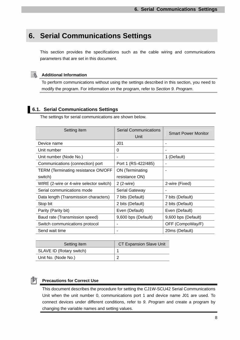
6.1. Serial Communications Settings
The settings for serial communications are shown below.
Setting item Serial Communications
Unit Smart Power Monitor
Device name J01 -
Unit number 0 -
Unit number (Node No.) - 1 (Default)
Communications (connection) port Port 1 (RS-422/485) -
TERM (Terminating resistance ON/OFF
switch)
ON (Terminating
resistance ON)
-
WIRE (2-wire or 4-wire selector switch) 2 (2-wire) 2-wire (Fixed)
Serial communications mode Serial Gateway -
Data length (Transmission characters) 7 bits (Default) 7 bits (Default)
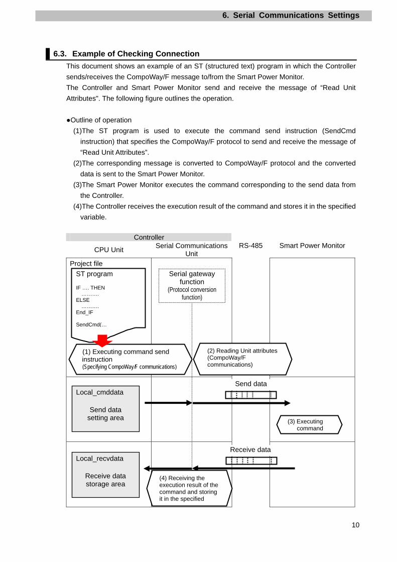
(2) Reading Unit attributes(CompoWay/F communications)
(3) Executing command
(4) Receiving the execution result of the command and storing it in the specified
7. Connection Procedure
11
7. Connection Procedure
This section describes the procedure for connecting the Smart Power Monitor to the Controller
via serial communications.
This document explains the procedures for setting up the Controller and Smart Power Monitor
from the factory default setting. For the initialization, refer to Section 8 Initialization Method.
7.1. Work Flow
Take the following steps to connect the Smart Power Monitor to the Controller via serial
communications.
7.2. Setting Up the Smart Power
Monitor
Set up the Smart Power Monitor.
↓
7.2.1. Hardware Settings Set the hardware switches on the Smart Power
Monitor and the CT Expansion Slave Unit.
↓
7.2.2. Parameter Settings Set the parameters for the Smart Power Monitor and
the CT Expansion Slave Unit.
↓
7.3. Setting Up the Controller Set up the Controller.
↓
7.3.1. Hardware Setting on the Serial
Communications Unit
Set the hardware switch on the Serial
Communications Unit and connect to the Controller.
↓
7.3.2. Starting the Sysmac Studio and
Importing the Project File
Start the Sysmac Studio and import the project file.
↓
7.3.3. Parameter Settings and Building Setting the parameters, execute the program check
on the project data and build the Controller.
↓
7.3.4. Connecting Online and
Transferring the Project Data
Connect online with the Sysmac Studio and transfer
the project data to the Controller.
↓
7.3.5. Transferring the Unit Settings Transfer the setting data of the Serial
Communication Unit.
↓
7.4. Checking the Serial
Communications
Execute the program and check that Serial
communications are normally performed.
↓
7.4.1. Executing the Program and
Checking the Receive Data
Execute the program and confirm that the correct
data are written to the variables of the Controller.
7. Connection Procedure
12
7.2. Setting Up the Smart Power Monitor
Set up the Smart Power Monitor.
7.2.1. Hardware Setting Set the hardware switches on the Smart Power Monitor and the CT Expansion Slave Unit.
Precautions for Correct Use
Make sure that the power supply is OFF when you perform the setting up.
1 Make sure that the power supply to the Smart Power Monitor is OFF. *If the power supply is turned
ON, settings may not be
applicable as described in the
following procedure.
2 Open the connector cover of the
Smart Power Monitor and the
CT Expansion Slave Unit.
Set No. 2 of each internal DIP
switch to OFF (CompoWay/F).
3 Set the rotary switch (SLAVE
ID) in the connector cover of the
CT Expansion Slave Unit to 1.
7. Connection Procedure
13
4 Connect the CT Expansion
Slave Unit to the Smart Power
Monitor.
(1) Connect the horizontally connecting hook.
Smart Power Monitor CT Expansion Slave Unit
(2) Install the connector.
5 Connect the serial cable to pins
7 and 8 of the Smart Power
Monitor.
Connect the power supply cable
to pins 1 and 2.
6 Connect the USB cable to the
USB port on the CT Expansion
Slave Unit.
Do not connect the other end
of the USB cable to the
personal computer. (Connect
it in step 2 of Section 7.2.2.)
Turn ON the power supply to the
Smart Power Monitor.
Serial cable
USB cable
7. Connection Procedure
14
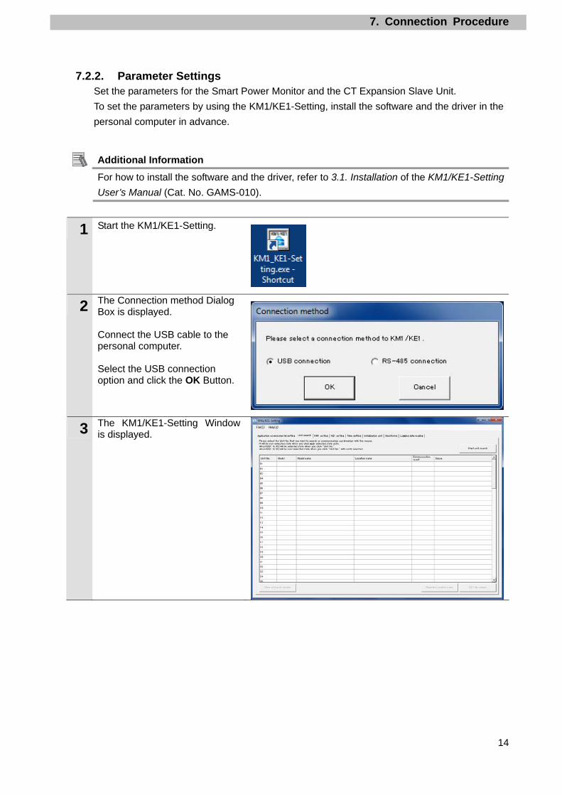
7.2.2. Parameter Settings Set the parameters for the Smart Power Monitor and the CT Expansion Slave Unit.
To set the parameters by using the KM1/KE1-Setting, install the software and the driver in the
personal computer in advance.
Additional Information For how to install the software and the driver, refer to 3.1. Installation of the KM1/KE1-Setting
User’s Manual (Cat. No. GAMS-010).
1 Start the KM1/KE1-Setting.
2 The Connection method Dialog Box is displayed. Connect the USB cable to the personal computer. Select the USB connection option and click the OK Button.
3 The KM1/KE1-Setting Window is displayed.
7. Connection Procedure
15
4 Select the Application environmental setting Tab. Select the USB connection Option for Connection method and select the used communication port for USB virtual COM port No. *If the personal computer has multiple serial ports, display the Windows’ Device Manager and find the COM port number, to which the KM1/KE1 is connected, under Ports (COM & LPT). (COM 16 is set in the right example.).
*To open Device Manager, select Device Manager from Control Panel.
5 Select the Unit search Tab. Select 01 under the Unit No. Column. The selected item is highlighted. Click the Start unit search Button.
6 A confirmation dialog box is displayed. Click the Yes Button.
・・・
7. Connection Procedure
16
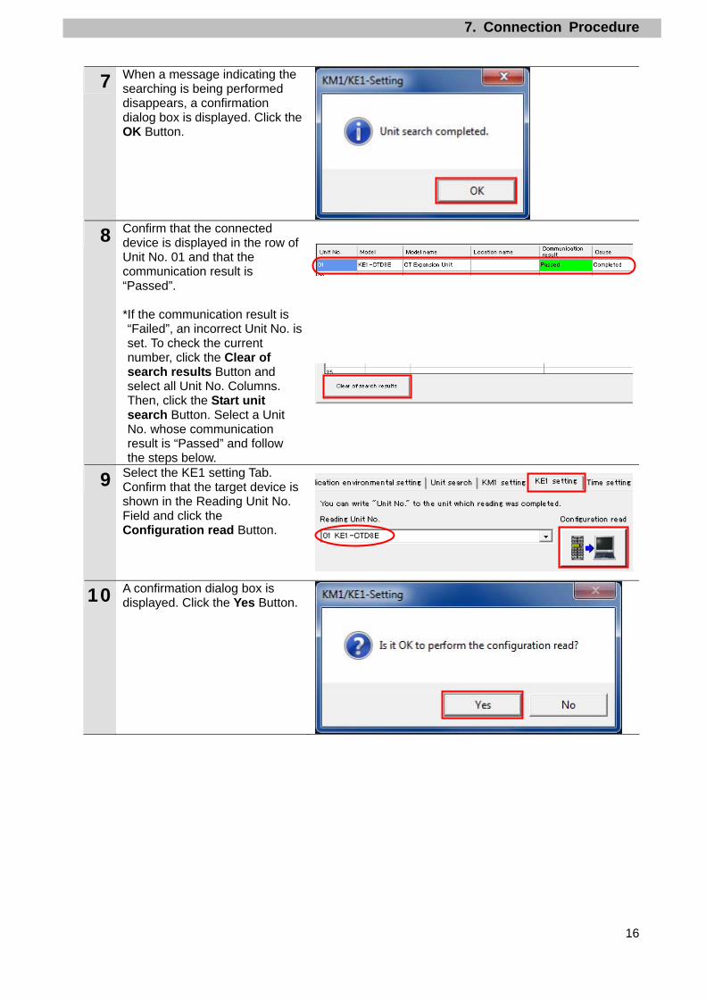
7 When a message indicating the searching is being performed disappears, a confirmation dialog box is displayed. Click the OK Button.
8 Confirm that the connected device is displayed in the row of Unit No. 01 and that the communication result is “Passed”. *If the communication result is “Failed”, an incorrect Unit No. is set. To check the current number, click the Clear of search results Button and select all Unit No. Columns. Then, click the Start unit search Button. Select a Unit No. whose communication result is “Passed” and follow the steps below.
9 Select the KE1 setting Tab. Confirm that the target device is shown in the Reading Unit No. Field and click the Configuration read Button.
10 A confirmation dialog box is displayed. Click the Yes Button.
7. Connection Procedure
17
11 Select the Communication setting Tab. Check the Unit No. If the value is different from the value (02) specified in Section 6.1, use the following procedure. Select 02 from the pull-down list of Unit No. *The setting range of Unit No. is 0 to 99. Set a value. (02 is set in this document.) The set value must not be duplicated between units.
The value of Unit No. changes to 02. The new value is displayed in red.
12 Confirm that the target device is displayed in the Writing Unit No. Field and click the Configuration write Button. A confirmation dialog box is displayed. Click the Yes Button. The Waiting for restart unit… Dialog Box is displayed. When the dialog box is closed, the rewrite operation is completed.
13 Select the Unit search Tab. Select the Unit No. that “Passed” in step 8 (here, 01 is selected.) and select 02 under the Unit No. Column. The selected items are highlighted as shown on the right. Click the Start unit search Button.
・・・
7. Connection Procedure
18
14 A confirmation dialog box is
displayed. Click the Yes Button
and OK Button.
15 Confirm that the connected device name (CT Expansion Unit) is displayed in the row of Unit No. 02 and that the communication result is “Passed”. *If the communication result is “Failed”, the Unit No. is not correctly set. Return to step 8 and perform the settings again.
16 Remove the USB cable that is
connected to the USB port on
the CT Expansion Slave Unit,
and connect it to the USB port
on the Smart Power Monitor.
17 In the same way as steps 13 and 14, select Unit No. 01 and 02 in the Unit search Tab and click the Start unit search Button.
(Refer to steps 13 and 14.)
18 Confirm that the connected device (Power Two-System Measurement Unit) is displayed in the row of Unit No. 01 and that the communication result is “Passed”.
USB cable
7. Connection Procedure
19
19 Select the KM1 setting Tab. Confirm that the target device is displayed in the Reading Unit No. Field, and click the Configuration read Button.
20 A configuration dialog box is displayed. Click the Yes Button.
21 Confirm that the values specified in Section 6.1. are displayed in the Communication setting Tab Page as shown on the right. *If the values are different, change a value from each pull-down list and click the Configuration read Button to write the changes.
22 Select Exit from the File Menu.
A confirmation dialog box is
displayed. Click the Yes Button.
7. Connection Procedure
20
7.3. Setting Up the Controller
Set up the Controller.
7.3.1. Hardware Settings on the Serial Communications Unit Set the hardware switches on the Serial Communications Unit.
Precautions for Correct Use
Make sure that the power supply is OFF when you perform the setting up.
1 Make sure that the power supply to the Controller is OFF. *If the power supply is turned ON, settings may not be applicable as described in the following procedure.
Check the each part name by
referring to the right figure.
*This setting is required to use the Port 1 of Serial Communications Unit.
2 Set the Unit number switch to 0.(The unit number is set to 0 as the factory default setting.)
3 Set the terminating resistance ON/OFF switch of port 1 to ON (Terminating resistance ON).
4 Set the 2-wire or 4-wire selector switch for port 1 to 2 (2-wire).
WIRE:2-wire/4-wire switch 2:2-wire;4:4-wire
TERM:terminating resistance ON/OFF switch OFF:Terminating resistance OFF ON:Terminating resistance ON
Unit number switch
7. Connection Procedure
21
5
Connect the Serial Communications Unit to the Controller as shown on the right. Connect the Smart Power Monitor and the Serial Communications Unit with the serial cable. Connect the Controller and the personal computer with the USB cable.
Serial cable
Serial Communications Unit
USB cable
Controller
End cover
Power Supply Unit
Smart Power Monitor
Personal computer
7. Connection Procedure
22
7.3.2. Starting the Sysmac Studio and Importing the Project File Start the Sysmac Studio and import the project file.
Install the Sysmac Studio and USB driver in the personal computer in advance.
1 Confirm that the personal
computer and Controller are
connected through the USB
cable, and turn ON the power
supply to the Controller.
Start the Sysmac Studio.
Click the Import Button.
*If a dialog box is displayed at
start confirming the access
right, select an option to start.
2 The Import file Dialog Box is
displayed. Select
OMRON_CWF485_EV100.smc
and click the Open Button.
*Obtain the project file from OMRON.
3 OMRON_CWF485_EV100
project is displayed.
The left pane is called Multiview
Explorer, the right pane is called
Toolbox and the middle pane is
called Edit Pane.
*If an error message is
displayed stating “Failed to
Load Descendants”, change the
version of the Sysmac Studio to
any version specified in 5.2.
Device Configuration or higher
version.
Edit Pane Toolbox Multiview Explorer
7. Connection Procedure
23
7.3.3. Parameter Settings and Building Set the parameters, execute the program check on the project data and build the Controller.
1 Double-click CPU/Expansion
Racks under Configurations
and Setup in the Multiview
Explorer.
2 The CPU/Expansion Racks Tab
is displayed on the Edit Pane.
Select the Serial
Communications Unit icon as
shown on the right.
Confirm that CJ1W-SCU42 is
displayed, the device name is
J01, and the unit number is 0.
*If the settings are different from the above, change the value.
Click Edit Special Unit
Settings.
3 The 0 [Unit 0]: Tab is displayed.
Select Port1: Serial Gateway
Settings from the pull-down list
of Parameter group to show.
7. Connection Procedure
24
4 Parameter group to show is set
to Port1: Serial Gateway
Settings.
The setting items for Port1:
Serial Gateway Settings are
Displayed.
Confirm that the following
settings are made.
•Port settings: User settings
•Serial communications mode:
Serial Gateway
*If the settings are different from the above, change a value from each pull-down list. After changing values, click the Apply Button.
5 Change other items as follows:
Data length: 7 bits
Stop bits: 7 bits
Stop bits: 2 bits
Parity: Even
Baud rate: 9600bps (Default)
*After changing the settings,
click the Apply Button in the
same way as step 4.
6 Double-click I/O Map under
Configurations and Setup in
the Multiview Explorer.
The I/O Map Tab is displayed
and the parameters of the Unit
are displayed.
7. Connection Procedure
25
7 Confirm that data in the Variable
Columns start with J01 and the
Global Variable is set in each
Variable Type Column in the I/O
Map.
*If the settings are different from the above, right-click on CJ1W-SCU42 and select Create Device Variable.
8 Double-click the Task Settings
under Configurations and
Setup in the Multiview Explorer.
9 The Task Settings Tab Page is
displayed in the Edit Pane.
Click the Program Assignment
Settings Button and confirm
that Program0 is set under
PrimaryTask.
10 Select Check All Programs
from the Project Menu.
11 The Build Tab Page is displayed
in the Edit Pane.
Confirm that "0 Errors" and "0
Warnings" are displayed.
7. Connection Procedure
26
12 Select Rebuild Controller from
the Project Menu.
A screen is displayed indicating
the conversion is being
performed.
13 Confirm that "0 Errors" and "0
Warnings" are displayed in the
Build Tab Page.
7. Connection Procedure
27
7.3.4. Connecting Online and Transferring the Project Data Connect online with the Sysmac Studio and transfer the project data to the Controller.
Always confirm safety at the destination node before you transfer a user
program, configuration data, setup data, device variables, or values in memory
used for CJ-series Units from the Sysmac Studio.
The devices or machines may perform unexpected operation regardless of the
operating mode of the CPU Unit.
Always confirm safety before you reset the Controller or any components.
1 Select Change Device from the
Controller Menu.
2 The Change Device Dialog Box
is displayed.
Confirm that the Device and
Version are set as shown on the
right and click the OK Button.
*If the settings are different from
the above, change a value from
each pull-down list.
3 If the settings were changed in
Step 2, the Build Dialog Box is
displayed. Click the Yes Button.
*This dialog box is not displayed
if no change was made.
7. Connection Procedure
28
4 Select Communications Setup
from the Controller Menu.
5 The Communications Setup
Dialog Box is displayed.
Select the Direct connection via
USB Option in the Connection
Type Field.
Click the OK Button.
6 Select Online from the
Controller Menu.
*If the dialog on the right is
displayed, the model or version
of the Controller does not
match that of the project file.
Check the model and version of
the Controller and device
settings of the project file.
Then, return to step 1 and try
again.
Click the OK Button to close
the dialog box. *The model and version displayed on the confirmation dialog box differ depending on the Controller used and the device settings of the project file.
*Example of confirmation dialog box
7. Connection Procedure
29
7 A confirmation dialog is
displayed. Click the Yes Button.
*The displayed dialog depends
on the status of the Controller
used. Click the Yes Button to
proceed with the processing.
*The displayed serial ID differs
depending on the device.
Additional Information For details on online connections to a Controller, refer to Section 5 Going Online with a Controller in the Sysmac Studio Version 1 Operation Manual (Cat. No. W504).
8 When an online connection is
established, a yellow bar is
displayed on the top of the Edit
Pane.
9 Select Synchronization from
the Controller Menu.
7. Connection Procedure
30
10 The Synchronization Dialog Box
is displayed.
Confirm that the data to transfer
(NJ501 in the right figure) is
selected. Then, click the
Transfer to Controller Button.
*After executing the Transfer to
Controller, the Sysmac Studio
project data is transferred to
the Controller and the data are
compared.
11 A confirmation dialog is
displayed. Click the Yes Button.
A screen stating "Synchronizing"
is displayed.
A confirmation dialog box is
displayed. Click the No Button.
12 Confirm that the synchronized
data is displayed with the color
specified by “Synchronized” and
that a message is displayed
stating "The synchronization
process successfully finished".
If there is no problem, click the
Close Button.
*A message stating "The
synchronization process
successfully finished" means
that the project data of Sysmac
Studio and that of the Controller
match. *If the synchronization fails,
check the wiring and repeat the
procedure described in this
section.
7. Connection Procedure
31
13 Select Reset Controller from
the Controller Menu.
*When Mode is set to RUN
Mode, Reset Controller cannot
be selected. In this case, select
Mode - PROGRAM Mode from
the Controller Menu to change
to PROGRAM mode and
perform this step.
14 A confirmation dialog box is
displayed several times. Click
the Yes Button.
15 The Controller is reset, and
Sysmac Studio goes offline.
The yellow bar on the top of the
Edit Pane disappears.
Use steps 6 to 8 to go online
again.
7. Connection Procedure
32
7.3.5. Transferring the Unit Settings Transfer the setting data of the Serial Communication Unit.
1 Select Mode - PROGRAM
Mode from the Controller Menu.
2 A confirmation dialog box is
displayed. Click the Yes Button.
3 PROGRAM mode is displayed
on the Controller Status Pane.
4 Double-click CPU/Expansion
Racks under Configurations
and Setup in the Multiview
Explorer.
Select the Serial
Communications Unit icon.
Click Edit Special Unit
Settings.
5 The 0 [Unit 0]: Tab is displayed.
Click the Transfer to Controller
Button.
7. Connection Procedure
33
6 A confirmation dialog box is
displayed.
Click the Yes Button.
A dialog box, which indicates
transferring is being performed,
is displayed. After that a
confirmation dialog box is
displayed.
Click the Yes Button.
7 The Port Selection Dialog Box is
displayed.
Select All ports and click the
OK Button.
8 A confirmation dialog box is
displayed.
Click the OK Button.
9 Select Port1: Serial Gateway
Settings from the pull-down list
of Parameter group to show.
Click the Compare Button.
10 Confirm that “≠” (mismatch) is
not shown in the red frame on
the right.
7. Connection Procedure
34
7.4. Checking the Serial Communications
Execute the program and confirm that serial communications are performed normally.
Sufficiently confirm safety before you change the values of variables on a Watch
Tab Page when the Sysmac Studio is online with the CPU Unit. Incorrect
operation may cause the devices that are connected to Output Units to operate
regardless of the operating mode of the Controller.
Precautions for Correct Use
Please confirm that the serial cable is connected before proceeding to the following steps.
If it is not connected, turn OFF the power of the devices, and then connect the serial cable.
7.4.1. Executing the Program and Checking the Receive Data Execute the program and confirm that the correct data are written to the variables of the
Controller.
1 Select Mode - RUN Mode from
the Controller Menu.
A confirmation dialog box is
displayed. Click the Yes Button.
2 RUN mode is displayed on the
Controller Status Pane.
3 Select Watch Tab Page from the
View Menu.
7. Connection Procedure
35
4 The Watch Tab Page 1 is
displayed in the lower section of
the Edit Pane.
5 Confirm that the variables shown
on the right are displayed in the
Name Columns.
*To add a variable, click Input
Name… *Program0 of the Name is
omitted from the following
descriptions.
6 Click TRUE on the Modify
Column of Input_Start.
The online value of Input_Start
changes to TRUE.
The program is operated and
CompoWay/F communications
are performed with the
destination device.
7 When the communications ends
normally, the online value of
Local_Status.Done that indicates
the execution status of the
program changes to TRUE and
each error code changes to 0.
*In the case of error end,
Local_Status.Error changes to
TRUE and the error code
corresponding to the error is
stored. For details on error
codes, refer to 9.7 Error
Process.
Start input
Error codes
Send data
Receive data
Program
execution status
7. Connection Procedure
36
8 When the communications ends
normally, the response data is
stored in Output_recvCWFdata.
(The send command is stored in
Local_cmdCWFdata.)
*The text data (Unit attributes)
differs depending on the device
used
*Refer to 9.2. Destination Device
Command for details on the
command.
Response data
01 = Node No.
00 = Subaddress
00 = Response code
0503 = Command (MRC,SRC)
0000 = Response code (MRES,SRES)
KM1-PMU2A = Text data (Unit attributes)
00E6 = Buffer size
8. Initialization Method
37
8. Initialization Method
This document explains the setting procedure from the factory default setting.
Some settings may not be applicable as described in this document unless you use the
devices with the factory default setting.
8.1. Initializing the Controller
To initialize the Controller, it is necessary to initialize the Serial Communications Unit and the
CPU Unit. Place in PROGRAM mode before initialization.
8.1.1. Serial Communications Unit To initialize the settings of the Serial Communications Unit, select Edit Special Unit Settings
of CJ1W-SCU42 in CPU/Expansion Racks from the Sysmac Studio.
Click the Return to default Button and click the Apply Button. Then, click the Transfer to
Controller Button.
8. Initialization Method
38
8.1.2. CPU Unit To initialize the settings of the Controller, select Clear All Memory from the Controller Menu of
the Sysmac Studio. The Clear All Memory Dialog Box is displayed. Click the OK Button.
8.2. Initializing the Smart Power Monitor
For information on how to initialize the Smart Power Monitor, refer to 3.6. Other functions in
the Smart Power Monitor User's Manual (Cat. No. N171) or 4.3.6. Initialization unit in the
28 03 aa bb AA BB CC DD cc dd FF GG HH II ee ff gg hh **
Command Response SCU→
CPU
CompoWay/F comm.. command
Command end code
Node No.
Sub address
End codeMRC SRC MRES SRES
Text
Command Response Output_rec
vCWFdata Node No.
Sub address
End code MRC SRC MRES SRES
Text
Controller
Destination
device
STX コマンド ETX 16#02
ノードNo.
サブア
ドレスSID
MRC SRC テキス
ト 16#03 BCC
STX コマンド レスポンス ETX
16#02
ノードNo.
サブアド
レス 終了コー
ド MRC SRC MRES SRES
テキ
スト 16#03 BCC
Send message (Command)
Receive message (Response)
Node No.
Sub address
Sub address
Node No.
End code
Command
Command Text
Text Response
9. Program
44
9.2. Destination Device Command
This section explains the destination device command used in this program.
9.2.1. Overview of the Command This program uses the Read Unit Attributes command to read the information from the
destination device.
Command name Description
Read Controller Attributes Reads the attributes of the destination device.
9.2.2. Detailed Description of the Function This section explains the “Read Controller Attributes” command.
SendCmd instruction send data
[DstNetAdr: Destination network address] Variable Setting item Data type Setting value
DstNetAdr Destination network address _sDNET_ADR - NetNo Network address USINT 16#00 Fixed: Local network NodeNo Node address USINT 16#00 Fixed: Within local controller UnitNo Unit address BYTE 16#80 Unit number 0 + Port number 1
[CommPort: Destination serial port] Variable Setting item Data type Setting value
DstNetAdr Destination serial port _ePORT _NONE Fixed
[CmdSize: Command data size] Variable Setting item Data type Setting value
DstNetAdr Command data size UINT 11 11 bytes
[Option: Response] Variable Setting item Data type Setting value
Option Response _sRESPONSE - isNonResp No response BOOL FALSE Response is required TimeOut Timeout time UINT 0 Default: 2 sec Retry Retry count USINT 3 3 times
9. Program
45
[CmdDat [ ]: Command array] Variable Setting item Data type Setting value
28 03 aa bb AA BB CC DD cc dd FF GG HH II ee ff gg hh **
Local_recvdata CompoWay/
F comm. command
Command end code
Node No.
Sub address
End code Command Response Text
Serial cable
Controller Destination device
(2)(1)
9. Program
48
9.4. Variables
The following lists the variables used in this program.
9.4.1. List of Variables The data types, external variables (user-defined global variables/system-defined variables),
and internal variables used in this program are listed below.
Data type (Structure)
[Communications processing status flags] Name Data type Description
sStatus STRUCT Structure of communications processing status flags
Busy BOOL Communications processing in progress flag TRUE: Processing is in progress. FALSE: Processing is not in progress.
Done BOOL Communications processing normal end flag TRUE: Normal end / FALSE: Other than normal end
Error BOOL Communications processing error end flag TRUE: Error end / FALSE: Other than error end
External variables
[User-defined global variables] Variable name Data type Description
Input_Start BOOL Communication start switch The program is started when this switch changes from FALSE to TRUE.
Output_recvCWFdata STRING[256] An area that stores the receive data (STRING type: 256 characters)
Output_CmdErrorID WORD An area that stores an error code of SendCmd instructionNormal end: 16#0000
Output_CmdErrorIDEx DWORD An area that stores an expansion error code of SendCmd instruction Normal end: 16#00000000
Output_TransErrCode WORD Transmission error status for a communication error An area that stores J01_P1_TransErrSta Normal end: 16#0000
Output_CWFErrCode1 WORD An area that stores the destination device end code for a destination device error Normal end: 16#0000
Output_CWFErrCode2 WORD An area that stores the destination device response code for a destination device error Normal end: 16#0000
[Device variables for CJ-series Unit CJ] (Serial Communications Unit) Variable name Data type Description
J01_P1_TransErr BOOL Transmission error J01_P1_TransErrSta BOOL Transmission error status
Additional Information For the variables of the Serial Communications Unit, refer to 2-3 Device Variable for
CJ-series Unit in the CJ-series Serial Communications Units Operation Manual for NJ-series
CPU Unit (Cat.No. W494).
9. Program
49
[System-defined variable] Variable name Data type Description
_Port_isAvailable BOOL Network Communications Instruction Enabled Flag TRUE: A port is available. FALSE: A port is not available.
Additional Information For the system-defined variables for the SendCmd instruction, refer to 2 Instruction
Descriptions - Communications Instruction in the NJ-series Instructions Reference Manual
(Cat. No. W502).
Internal variables (instance variables)
The internal variables used to execute the function blocks in the program are listed below.
An internal variable is called an "instance". The name of each function block to use is
specified as the data type of the variable.
[Instance for user-defined function block] Variable name Data type Description
CWFCmdsSet_instance CWFCmdsSet Sets the byte sizes of send/receive data and sets the send message.
*For the user-defined function block, refer to 9.5.3. Detailed Description of the Function Block.
[Instance for SendCmd instruction] Variable name Data type Description
SendCmd_instance SendCmd This function block sends the command to the Serial Communications Unit by using the Serial Gateway function.
Additional Information For the SendCmd instruction, refer to Communications Instructions in Section 2 Instruction
Descriptions of the NJ-series Instructions Reference Manual (Cat. No. W502).
Internal variables Variable name Data type Description
Local_Status sStatus Communications processing status flags This variable is defined as sStatus structure.
Local_State DINT Processing number Local_ExecFlgs BOOL Communications instruction execution flag Local_InitialSettingOK BOOL Initialization processing normal setting flag Local_DstNetAdr _sDNET_ADR Destination address for SendCmd instruction setting Local_CommPort _ePORT Destination serial port for SendCmd instruction setting Local_sendSize UINT Send command data size for SendCmd instruction settingLocal_Option _sRESPONSE Response setting for SendCmd instruction setting
Local_cmddata ARRAY[0..255] OF BYTE
Command array for SendCmd instruction setting (256 bytes)
Local_recvdata ARRAY[0..255] OF BYTE
Response storage array for SendCmd instruction setting (256 bytes)
Local_cmdCWFdata STRING[256] An area that stores the send data (STRING type: 256 characters)
9. Program
50
9.5. ST Program
9.5.1. Functional Components of the Program This program is written in the ST language. The functional components are as follows:
Major classification Minor classification Description
1. Communications processing
1.1. Starting the communications processing 1.2. Clearing the communications processing
status flags 1.3. Communications processing in progress
status
The communications processing is started.
2. Initialization processing
2.1. Initializing the communications instruction2.2. Initializing the communications execution
instruction flag 2.3. Initializing the error code storage areas 2.4. Setting the SendCmd instruction control
data 2.5. Setting the send variables 2.6. Initialization setting end processing
The receive data storage areas and the error code storage areas are initialized. The parameters and send data are set for the SendCmd instruction (CompoWay/F communications).
3. CompoWay/F communications processing
3.1.Determining the communications processing status and setting the execution flag
3.2. Executing the communications instruction
SendCmd instruction (CompoWay/F communications) are executed. Whether the execution ends normally or ends in an error is detected.
4. Processing number error process
4.1. Processing number error process The error processing is performed when a non-existent number is detected.
9. Program
51
9.5.2. Program List The program is shown below. The communications setting and send data (command data) setting which need to be changed depending on the destination device are set in the function block (CWFCmdsSet). For information on how to change these values, refer to 9.5.3 Detailed Description of the Function Block.
Program: Program0 (General-purpose serial communications connection check program)
1. Communications processing
9. Program
52
2. Initialization processing
9. Program
53
9. Program
54
3. CompoWay/F communications processing
9. Program
55
4. Processing number error process
9. Program
56
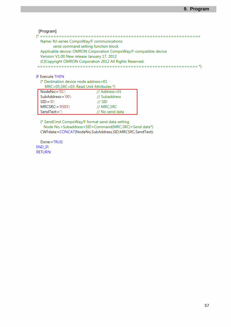
9.5.3. Detailed Description of the Function Block The user-defined function block is shown below.
The code which you need to edit according to the destination device is indicated by the red
frames on the function block below.
CWFCmdsSet function block (CompoWay/F communications send command setting) Instruction Name ST expression
Output_CWFErrCode 1 and 2 16#FFFF 16#FFFF 16#xxxx 16#FFFF 16#xxxx *If Input_Start changes from TRUE to FALSE during execution (Busy=ON), a normal end or an error end is output for 1 period after the processing is completed (Busy=OFF).
9. Program
59
9.7. Error Process
The errors that occur when this program is executed are shown below.
9.7.1. SendCmd Instruction Errors The error codes that are generated for errors in the SendCmd instruction are shown below.
0000 Successfully completed NA 0401 Command not supported 1 1001 Exceeding command length 2 1002 Short command length 3 1101 Area type error 4 1103 Error for out-of-range starting address 5 1104 Error for out-of-range end address 6 1003 Element count/number of data not matched 7 110B Exceeding response length 8 1100 Parameter error 9 3003 Read only 10 2203 Operation error 11
Additional Information For details and troubleshooting of the destination device errors, refer to the Smart Power
Monitor User's Manual (Cat. No. N171) and the Smart Power Monitor Communication
Manual for Smart Measurement and Monitoring Instrument (Cat. No. N172).
10. Revision History
63
10. Revision History
Revision
code
Date of revision Revision reason and revision page