NEW ZEALAND TIMBER DESIGN JOURNAL VOL 20 · ISSUE 1 3 1. INTRODUCTION 1.1 PROJECT BACKGROUND In an effort to promote the use of timber in multi-storey construction the Ministry of Agriculture and Forestry agreed to invest $1M into the design and construction of an innovative timber building. The completed building was required to demonstrate the innovative use of timber, and showcase to the construction industry that multi–storey commercial construction in timber is now a viable option. The Nelson-Marlborough Institute of Technology (NMIT) Arts and Media building project was awarded to Aurecon following a national design competition open to all consultants. Aurecon with Irving Smith Jack Architects won the competition against a number of New Zealand’s top architects and engineers. Figure 1 shows a 3D rendering of the finished building model. NMIT ARTS & MEDIA BUILDING - DAMAGE MITIGATION USING POST-TENSIONED TIMBER WALLS * C.P. Devereux 1 , T.J. Holden 1 , A.H. Buchanan 2 & S. Pampanin 2 1 Aurecon New Zealand. 2 Department of Civil and Natural Resources Engineering, University of Canterbury, Christchurch. Email: [email protected]ABSTRACT The NMIT Arts & Media Building is the first in a new generation of multi-storey timber structures. It employs an advanced damage avoidance earthquake design that is a world first for a timber building. Aurecon structural engineers are the first to use this revolutionary Pres-Lam technology developed at the University of Canterbury. This technology marks a fundamental change in design philosophy. Conventional seismic design of multi-storey structures typically depends on member ductility and the acceptance of a certain amount of damage to beams, columns and walls. The NMIT seismic system relies on pairs of coupled LVL shear walls that incorporate high strength steel tendons post-tensioned through a central duct. The walls are centrally fixed allowing them to rock during a seismic event. A series of U-shaped steel plates placed between the walls form a coupling mechanism and act as dissipators to absorb seismic energy. The design allows the primary structure to remain essentially undamaged while readily replaceable connections act as plastic fuses. In this era where sustainability is becoming a key focus, the extensive use of timber and engineered-wood products such as LVL make use of a natural resource all grown and manufactured within a 100km radius of Nelson. This project demonstrates that there are now cost effective, sustainable and innovative solutions for multi-story timber buildings with potential applications for building owners in seismic areas around the world. * Previously presented at 9th Pacific Conference on Earthquake Engineering, 14-16 April, 2011, Auckland, New Zealand Figure 1. 3D view of the NMIT Arts and Media Building structure.
In an effort to promote the use of timber in multi-storey construction the Ministry of Agriculture and Forestry agreed to invest $1M into the design and construction of an innovative timber building. The completed building was required to demonstrate the innovative use of timber, and showcase to the construction industry that multi–storey commercial construction in timber is now a viable option.
The Nelson-Marlborough Institute of Technology (NMIT) Arts and Media building project was awarded to Aurecon following a national design competition open to all consultants. Aurecon with Irving Smith Jack Architects won the competition against a number of New Zealand’s top architects and engineers. Figure 1 shows a 3D rendering of the finished building model.
NMIT ARTS & MEDIA BUILDING - DAMAGE MITIGATION USING POST-TENSIONED TIMBER WALLS* C.P. Devereux1, T.J. Holden1, A.H. Buchanan2 & S. Pampanin2 1Aurecon New Zealand. 2Department of Civil and Natural Resources Engineering, University of Canterbury, Christchurch. Email: [email protected] ABSTRACT
The NMIT Arts & Media Building is the first in a new generation of multi-storey timber structures. It employs an advanced damage avoidance earthquake design that is a world first for a timber building. Aurecon structural engineers are the first to use this revolutionary Pres-Lam technology developed at the University of Canterbury.
This technology marks a fundamental change in design philosophy. Conventional seismic design of multi-storey structures typically depends on member ductility and the acceptance of a certain amount of damage to beams, columns and walls. The NMIT seismic system relies on pairs of coupled LVL shear walls that incorporate high strength steel tendons post-tensioned through a central duct. The walls are centrally fixed allowing them to rock during a seismic event. A series of U-shaped steel plates placed between the walls form a coupling mechanism and act as dissipators to absorb seismic energy. The design allows the primary structure to remain essentially undamaged while readily replaceable connections act as plastic fuses.
In this era where sustainability is becoming a key focus, the extensive use of timber and engineered-wood products such as LVL make use of a natural resource all grown and manufactured within a 100km radius of Nelson.
This project demonstrates that there are now cost effective, sustainable and innovative solutions for multi-story timber buildings with potential applications for building owners in seismic areas around the world.
* Previously presented at 9th Pacific Conference on Earthquake Engineering, 14-16 April, 2011, Auckland, New Zealand
Figure 1. 3D view of the NMIT Arts and Media Building structure.
same time takes a conservative enough approach to ensure the design will meet the building performance criteria required. Timber innovation is also provided in other aspects of the building design. Firstly, the long span floor beams have been designed as composite sections, engaging the concrete topping slab. This is one of the first times that this type of beam technology has been used commercially in New Zealand, producing a timber section able to compete with steel or concrete. Secondly, the flooring system makes use of pre-fabricated stressed skin panels. These panels act much like a concrete pre-cast double-T, and essentially provide an alternative to a traditional Stahlton or Unispan concrete floor.
2. DESCRIPTION OF STRUCTURAL SYSTEMS
The new NMIT Arts and Media facility is divided into three blocks: The three storey studio/gallery/teaching wing, the workshop wing and the music and drama wing. The main focus of this paper is on the structural system incorporated in the three storey wing where much of the timber design innovation has been applied. The building footprint for the main three story wing covers an area of approximately 500 m2 per floor.
2.2 LVL (LAMINATED VENEER LUMBER)
Nelson Pine LVL was a natural choice given the proximity of their LVL plant to the building site. The LVL timber product has strength properties (in the range of 30-40 MPa) that allow for the fabrication of beams, columns and walls at sizes similar to those used in concrete design. It also provides the designer the ability to use traditional structural grids allowing long clear spans and large floor plates free of columns. The challenge for structural designers is the low elastic modulus of LVL, typically in the range of 11 GPa. This is where innovative design is required in the use of composite timber and concrete sections to ensure that deflection is effectively controlled. A displacement-based design approach [12] was adopted to ensure that deformations and drift-based limits were not exceeded.
All LVL timber beams, columns and walls were fabricated off-site in a manner similar to pre-cast concrete. With the ability to transport large sections to site, due to its light weight, LVL allows fewer site connections and considerable speed of erection.
A main feature of the NMIT project was the minimisation of its carbon footprint. Using LVL supports our local forestry and timber manufacturing industries. In this new era where sustainability is a key focus, the timber design makes full use of a natural resource grown and manufactured within a 100 km radius of Nelson. All of the structural timber supplied for the project was locally grown, with each individual panel of LVL traceable to a specific forest plantation.
1.2 INNOVATION IN TIMBER DESIGN
NMIT represents a “world first” in terms of innovative timber technology and seismic design. Seismic lateral bracing is provided through pairs of LVL coupled shear walls that incorporate high strength steel tendons post-tensioned through a central duct. The walls are centrally fixed which allows them to rock, rather than sustaining damaged to the plastic hinge region, during a seismic event. Pairs of U-shaped Flexural Steel Plates (UFPs) are placed between the panels to provide additional moment-resisting coupling, as well as, act as energy dissipaters/fuses absorbing seismic energy.
These concepts are part of a new philosophy in Performance-Based Engineering. The use of rocking/dissipative jointed ductile connections relying upon the use of post-tensioning techniques (typically referred to as PRESSS-technology) was originally developed in the US during the late 1990s for precast concrete structures [8,9,11].
The system minimises damage to the structure by focusing plastic deformations on readily replaceable connections, allowing the building to remain operational after a major earthquake event. The structural solution adopted has embraced this emerging new design philosophy providing a landmark timber building. The design is based on the latest and extensive research carried out by the University of Canterbury to develop Prestressed Laminated timber solutions (Pres-Lam) for multi-storey timber buildings described by Pampanin et al [2006], Iqbal et al [2007], Smith et al [2008], and Buchanan et al [2008]. Such patented technology, owned by a spin-off company of the University of Canterbury (Prestressed Timber limited) is now being promoted through New Zealand and Australia by the R&D Research Consortium, STIC Ltd (Structural Timber Innovation Company), as the “EXPAN building system incorporating Pres-Lam technology”.
Essential to the delivery of any new technology is the ability to meet standards and regulations such as the New Zealand Building Code. With this in mind the assistance of University of Canterbury researchers was enlisted. A university design team, including Dr Andy Buchanan, Dr Stefano Pampanin and PhD students Michael Newcombe and Kam Weng, provided valuable comments and feedback throughout the structural design phase. This team assisted Alistair Cattanach of Dunning Thornton Consultants to peer review critical aspects of the design to ensure a robust solution. Non-linear time-history analyses, using lumped plasticity models implemented in Ruaumoko [2], and based on the latest procedures developed and extensively validated for Pres-Lam connections were carried out as part of the seismic design verification.
The design takes a balanced approach in that it merges new advances with existing technology. As a showcase to the construction industry the application of this new technology provides a cost competitive option, but at the
left at the bottom of the panel. An additional opening was provided at the top of the wall to accommodate stressing jacks. Strain gauges have been placed on the bars for ongoing monitoring and maintenance to ensure that relaxing of the bars, creep, and shrinkage of the timber do not compromise the initial design post-tensioning. The initial design stress in this case is approximately 60% of yield (e.g. 350 kN per rod for a total of 1400 kN axial load). At the design level drift, elongation of the rods due to wall uplift increases the tensile stress, which was checked to under 90% of yield. It is important for the re-centering behaviour of the structure that the post-tensioning rods are not overstressed beyond their elastic yield limit.
U-shaped flexural plates (UFPs) act as energy dissipation devices between the timber panels. Six sets of UFPs, (two pairs per floor) couple together the wall units. 140 x 16 Grade 300 MPa mild steel plates were machined and connected to the panels via friction grip bolts screwed into pre-installed, epoxied glued couplers. Oversized holes in the UFP plates provided a building tolerance of +/-5 mm, which was sufficient given the accuracy inherent in the prefabricated construction. This arrangement allowed the UFP’s to be installed following placement of the LVL panels aiding construction, as well as, providing a means in which to replace them if required following a major seismic event. The use of UFPs is not a recent technological development having been first researched by Kelly et al [1972] and extensively and successfully tested for both precast concrete and timber solutions [3,11].
2.2 POST-TENSIONED LVL SHEAR WALLS
The lateral load resisting system promotes the very latest in damage avoidance technology for timber structures. As this is a world first commercial application of a post-tensioned hybrid rocking wall system in timber, precautions were taken to ensure that the system would not be too highly stressed at the design limits considered. Tests and numerical analysis performed at the University of Canterbury have shown that this system can be easily used for buildings up to six storeys in height [3,14]. Applying this technology to a three storey building is seen as a first step in showcasing its potential to the construction industry.
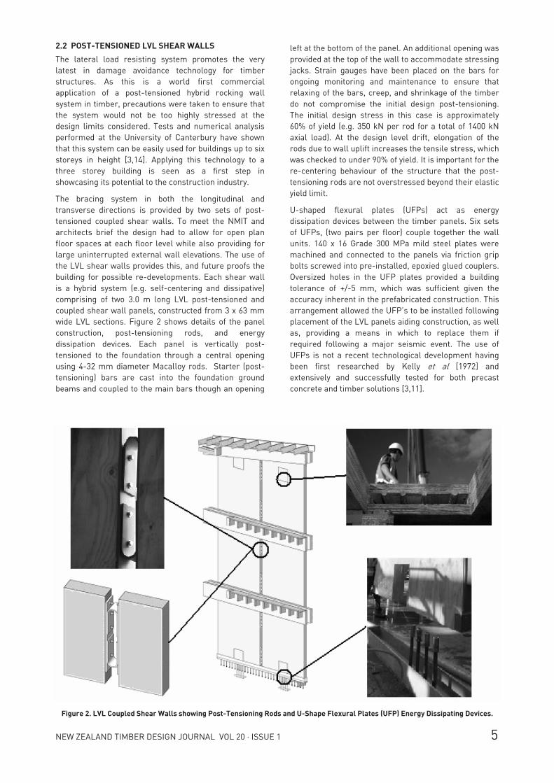
The bracing system in both the longitudinal and transverse directions is provided by two sets of post-tensioned coupled shear walls. To meet the NMIT and architects brief the design had to allow for open plan floor spaces at each floor level while also providing for large uninterrupted external wall elevations. The use of the LVL shear walls provides this, and future proofs the building for possible re-developments. Each shear wall is a hybrid system (e.g. self-centering and dissipative) comprising of two 3.0 m long LVL post-tensioned and coupled shear wall panels, constructed from 3 x 63 mm wide LVL sections. Figure 2 shows details of the panel construction, post-tensioning rods, and energy dissipation devices. Each panel is vertically post-tensioned to the foundation through a central opening using 4-32 mm diameter Macalloy rods. Starter (post-tensioning) bars are cast into the foundation ground beams and coupled to the main bars though an opening
Figure 2. LVL Coupled Shear Walls showing Post-Tensioning Rods and U-Shape Flexural Plates (UFP) Energy Dissipating Devices.
friction and direct bearing. Screw piles cast into each end of the shear wall ground beams carry the design uplift and bearing loads, with reinforced concrete bored piles providing shear transfer into the ground.
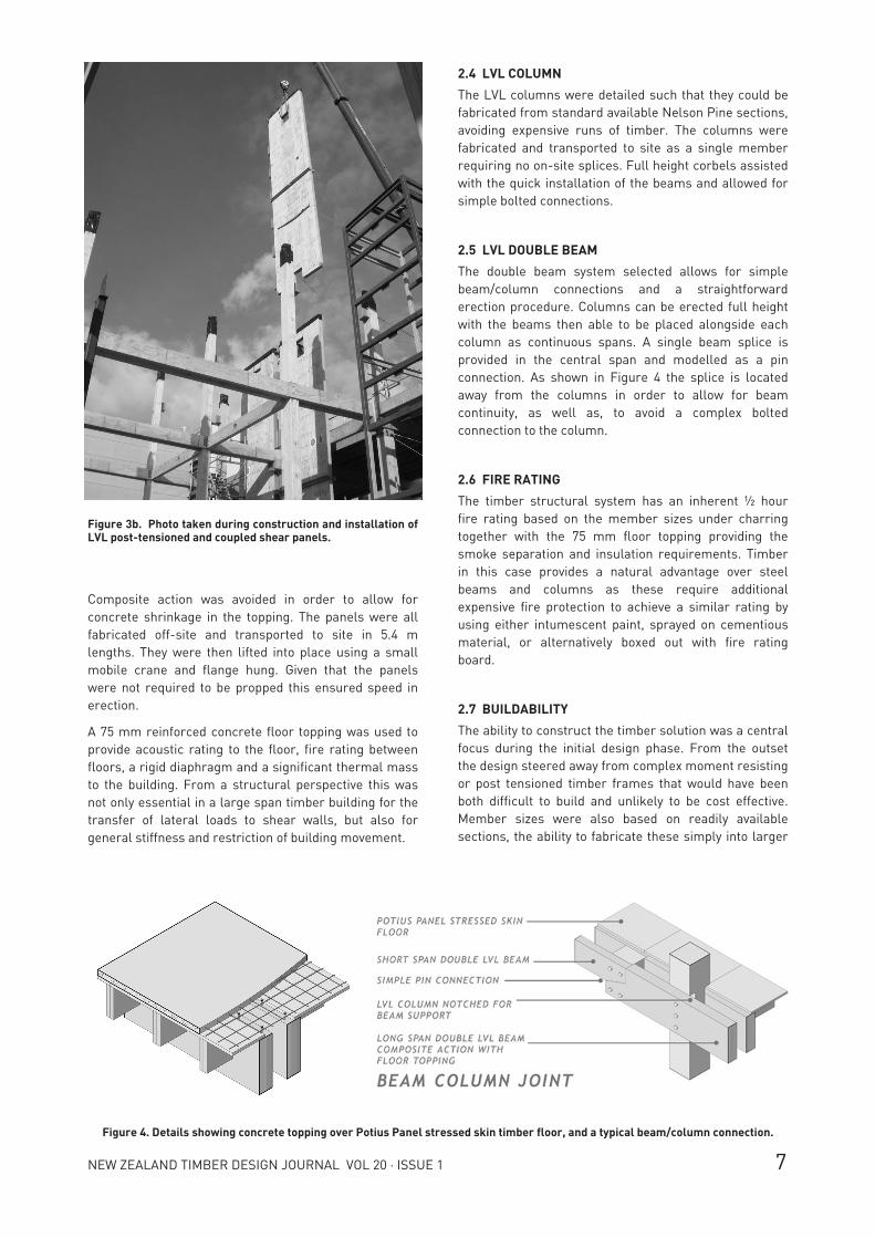
Figure 3 shows the installation process and construction method used in erecting the LVL panels.
The panels are connected to timber drag beams via 200 mm steel dowels, which in turn, transfer shears forces into the concrete floor diaphragms through multiple sets of coach screws. The dowels allow the panels to rock whilst minimising the curvature and deformations introduced in the floor beams and slab. Lateral restraint is provided by four bolts in vertical slots positioned at each end of the panels.
2.3 STRESSED SKIN FLOOR PANELS
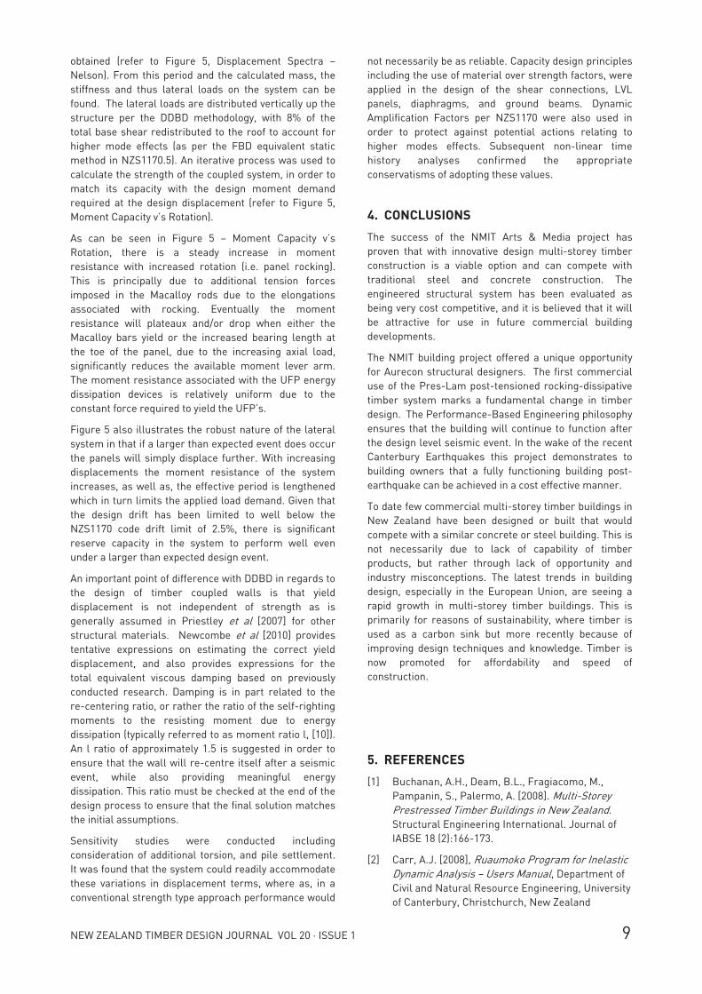
The stressed skin floor panels, trade name Potius Panels, have been in production for several years in Nelson and used on long span residential projects. They consist of two 360 x 90 timber LVL joists per panel fixed to a 36 mm thick LVL slab, and were selected for their long span capability along with the ability to support a concrete floor topping. Figure 4 shows the build up of a typical floor section. This technology is not new, as stressed skin panels have been used with timber and plywood sheets previously. What is new is the use of LVL, as this provides the ability to have continuous joists and sheets avoiding the cost of complex splices and joints.
Energy dissipation comes in the form of uniform bending of the UFP’s as the walls rock. Relative movement along the inside edges of the walls cause the plates to roll, inducing a uniform flexure. The gap between the panels is approximately 200 mm, which strongly influences the amount of energy dissipation and moment capacity provided to the system. The larger the gap, the less tight the radius of the plate, the smaller the flexural demand and thus energy absorbed. A 20 mm steel plate is epoxy dowelled to the inside ends of the walls providing a continuous tie to evenly transfer loads from the UFP’s into the panels. The post-tensioning and energy dissipation devices provide moment resistance based on the level of displacement at the joint. As is typically employed with post-tensioned hybrid (rocking-dissipative) systems and connections, the initial post-tensioning force applied must be great enough to overcome the resistance of the energy dissipators allowing the system to re-centre itself following a seismic event.
The bottom corners of the LVL panels are armoured with a folded steel plate, and set into a fabricated steel shoe epoxy dowelled into the top of the foundation ground beams. The steel shoe is sheathed with Teflon washers which both reduce friction, as well as, prevent the wall from “catching” while rocking. It is important for the panels to be adequately restrained laterally, while at the same time not jamming or stepping out of the steel shoe during an earthquake event. Shear from the LVL coupled panels is transferred to the ground beams through
Figure 3a. Photo taken during construction and installation of LVL post-tensioned and coupled shear panels.
The LVL columns were detailed such that they could be fabricated from standard available Nelson Pine sections, avoiding expensive runs of timber. The columns were fabricated and transported to site as a single member requiring no on-site splices. Full height corbels assisted with the quick installation of the beams and allowed for simple bolted connections.
2.5 LVL DOUBLE BEAM
The double beam system selected allows for simple beam/column connections and a straightforward erection procedure. Columns can be erected full height with the beams then able to be placed alongside each column as continuous spans. A single beam splice is provided in the central span and modelled as a pin connection. As shown in Figure 4 the splice is located away from the columns in order to allow for beam continuity, as well as, to avoid a complex bolted connection to the column.
2.6 FIRE RATING
The timber structural system has an inherent ½ hour fire rating based on the member sizes under charring together with the 75 mm floor topping providing the smoke separation and insulation requirements. Timber in this case provides a natural advantage over steel beams and columns as these require additional expensive fire protection to achieve a similar rating by using either intumescent paint, sprayed on cementious material, or alternatively boxed out with fire rating board.
2.7 BUILDABILITY
The ability to construct the timber solution was a central focus during the initial design phase. From the outset the design steered away from complex moment resisting or post tensioned timber frames that would have been both difficult to build and unlikely to be cost effective. Member sizes were also based on readily available sections, the ability to fabricate these simply into larger
Composite action was avoided in order to allow for concrete shrinkage in the topping. The panels were all fabricated off-site and transported to site in 5.4 m lengths. They were then lifted into place using a small mobile crane and flange hung. Given that the panels were not required to be propped this ensured speed in erection.
A 75 mm reinforced concrete floor topping was used to provide acoustic rating to the floor, fire rating between floors, a rigid diaphragm and a significant thermal mass to the building. From a structural perspective this was not only essential in a large span timber building for the transfer of lateral loads to shear walls, but also for general stiffness and restriction of building movement.
Figure 4. Details showing concrete topping over Potius Panel stressed skin timber floor, and a typical beam/column connection.
Figure 3b. Photo taken during construction and installation of LVL post-tensioned and coupled shear panels.
LVL panels [5,6]. Figure 5 illustrates the basic DDBD approach used in the lateral system design. The structure is initially converted into an equivalent single degree of freedom system, where an effective mass is found to act at an effective height. Based on the initial design drift chosen and the length of the LVL panels a displacement profile is calculated. As expected the deflected profile of the building was found to be largely linear with the majority of rotation occurring at the base of the shear panels. An effective ductility is obtained from the calculated yield and design (target) displacement. It is assumed that at yield all deformations are due to elastic deformations of the wall panel itself, though the UFP’s theoretically yield under any initial displacement [4].
The 5% damped pseudo-displacement spectrum, derived from the NZS1170.5 acceleration spectrum, is scaled by the estimated system equivalent viscous damping, and in conjunction with the effective design displacement previously established the required system period is
sections, and simple connection detailing. It was the view that simplicity reduces the construction risk, and maximises the building efficiency. To test this theory a local builder was engaged to build a scale model of a typical beam column joint and floor panel. These were built in a couple of hours from hand sketch details with not a single query from the builder. A full report on the cost and time of construction is in progress, building on the work of Smith et al [2009].
3. LATERAL ANALYSIS
A Direct Displacement Based Design (DDBD) philosophy [12] was used in the lateral analysis of the superstructure. The design techniques used are similar, and in some cases adapted from the methods used by PRESSS-technology (Precast Seismic Structural Systems), developed in the late 1990s in the US under the coordination of the University of San Diego [9,11], and has been previously utilised in a number of overseas, as well as, New Zealand based projects [8].
Significant variation can occur between lateral forces calculated using a traditional Force Based Design (FBD) and DDBD. Often inelastic displacements for a structure designed using FBD will be much larger than predicted. In addition, the elastic deformations in timber structures may also be much higher than predicted, thus the assumed ductility used (often up to four in some case), can be unrealistic [5,6].
The building was designed according to the NZS1170.5 displacement spectra for a 1/500yr return period earthquake, soil type C, in Nelson. A design drift of 1.0% was targeted as an appropriate limit, following a Performance-Based Engineering philosophy. This limit is increased to 1.5% when considering additional torsional effects and possible pile settlements. Careful design consideration was given to non-structural items, such as windows, services, and internal linings, as these are important elements when ensuring that the building will remain operational following the design level event.
The lateral load design is governed by seismic actions due to the mass of the building and the high (approximately 4 m) inter-storey heights. The calculated design wind loads were found to be less than half that of the seismic loading, and as such the bracing panels were designed to respond in an elastic manner without rocking. Given the building is largely constructed in timber, it is much lighter than an equivalent structure built in concrete. As such the seismic loads are largely reduced, which in particular provides significant savings in terms of the foundation construction.
During the design phase close reference was made to Priestley et al [2007] in regards to the DDBD procedure, and more recent developments for timber jointed ductile connections in determining an appropriate flag shaped hysteresis loop model and associated area based equivalent viscous damping, as well as, estimating the appropriate timber yield displacement behaviour of the
not necessarily be as reliable. Capacity design principles including the use of material over strength factors, were applied in the design of the shear connections, LVL panels, diaphragms, and ground beams. Dynamic Amplification Factors per NZS1170 were also used in order to protect against potential actions relating to higher modes effects. Subsequent non-linear time history analyses confirmed the appropriate conservatisms of adopting these values.
4. CONCLUSIONS
The success of the NMIT Arts & Media project has proven that with innovative design multi-storey timber construction is a viable option and can compete with traditional steel and concrete construction. The engineered structural system has been evaluated as being very cost competitive, and it is believed that it will be attractive for use in future commercial building developments.
The NMIT building project offered a unique opportunity for Aurecon structural designers. The first commercial use of the Pres-Lam post-tensioned rocking-dissipative timber system marks a fundamental change in timber design. The Performance-Based Engineering philosophy ensures that the building will continue to function after the design level seismic event. In the wake of the recent Canterbury Earthquakes this project demonstrates to building owners that a fully functioning building post-earthquake can be achieved in a cost effective manner.
To date few commercial multi-storey timber buildings in New Zealand have been designed or built that would compete with a similar concrete or steel building. This is not necessarily due to lack of capability of timber products, but rather through lack of opportunity and industry misconceptions. The latest trends in building design, especially in the European Union, are seeing a rapid growth in multi-storey timber buildings. This is primarily for reasons of sustainability, where timber is used as a carbon sink but more recently because of improving design techniques and knowledge. Timber is now promoted for affordability and speed of construction.
5. REFERENCES
[1] Buchanan, A.H., Deam, B.L., Fragiacomo, M., Pampanin, S., Palermo, A. [2008]. Multi-Storey Prestressed Timber Buildings in New Zealand. Structural Engineering International. Journal of IABSE 18 (2):166-173.
[2] Carr, A.J. [2008], Ruaumoko Program for Inelastic Dynamic Analysis – Users Manual, Department of Civil and Natural Resource Engineering, University of Canterbury, Christchurch, New Zealand
obtained (refer to Figure 5, Displacement Spectra – Nelson). From this period and the calculated mass, the stiffness and thus lateral loads on the system can be found. The lateral loads are distributed vertically up the structure per the DDBD methodology, with 8% of the total base shear redistributed to the roof to account for higher mode effects (as per the FBD equivalent static method in NZS1170.5). An iterative process was used to calculate the strength of the coupled system, in order to match its capacity with the design moment demand required at the design displacement (refer to Figure 5, Moment Capacity v’s Rotation).
As can be seen in Figure 5 – Moment Capacity v’s Rotation, there is a steady increase in moment resistance with increased rotation (i.e. panel rocking). This is principally due to additional tension forces imposed in the Macalloy rods due to the elongations associated with rocking. Eventually the moment resistance will plateaux and/or drop when either the Macalloy bars yield or the increased bearing length at the toe of the panel, due to the increasing axial load, significantly reduces the available moment lever arm. The moment resistance associated with the UFP energy dissipation devices is relatively uniform due to the constant force required to yield the UFP’s.
Figure 5 also illustrates the robust nature of the lateral system in that if a larger than expected event does occur the panels will simply displace further. With increasing displacements the moment resistance of the system increases, as well as, the effective period is lengthened which in turn limits the applied load demand. Given that the design drift has been limited to well below the NZS1170 code drift limit of 2.5%, there is significant reserve capacity in the system to perform well even under a larger than expected design event.
An important point of difference with DDBD in regards to the design of timber coupled walls is that yield displacement is not independent of strength as is generally assumed in Priestley et al [2007] for other structural materials. Newcombe et al [2010] provides tentative expressions on estimating the correct yield displacement, and also provides expressions for the total equivalent viscous damping based on previously conducted research. Damping is in part related to the re-centering ratio, or rather the ratio of the self-righting moments to the resisting moment due to energy dissipation (typically referred to as moment ratio l, [10]). An l ratio of approximately 1.5 is suggested in order to ensure that the wall will re-centre itself after a seismic event, while also providing meaningful energy dissipation. This ratio must be checked at the end of the design process to ensure that the final solution matches the initial assumptions.
Sensitivity studies were conducted including consideration of additional torsion, and pile settlement. It was found that the system could readily accommodate these variations in displacement terms, where as, in a conventional strength type approach performance would
[9] Pampanin, S. [2005], Emerging solutions for High Seismic Performance of Precast/Prestressed Concrete Buildings Journal of Advanced Concrete Technology, "High Performance Systems" 3(2): 202-223.
[10] Pampanin, S., Palermo, A., Buchanan, A., Fragiacomo, M., Deam, B.L. [2006]. Code Provisions for Seismic Design of Multi-storey Post-tensioned Timber Buildings. CIB WG18 – Timber Structures. Meeting No 39. Florence, Italy.
[11] Priestley, M. J. N., Sritharan, S., Conley, J. R., and Pampanin, S. [1999], Preliminary Results and Conclusions from the PRESSS Five-story Precast Concrete Test-Building, PCI Journal, 44(6): 42-67.
[12] Priestley, M. J. N., Calvi, G. M., and Kawalsky, M. J. [2007], Displacement-Based Seismic Design of Structures, IUSS PRESS, Pavia, Italy.
[13] Smith, T., Fragiacomo, M. Pampanin, S. and Buchanan, A.H. [2009], Construction Time and Cost for Post-tensioned Timber Buildings, Construction Materials, Inst. of Civil Eng., UK., 162 (CM4): 141-149.
[14] Smith T., Pampanin S., Fragiacomo M., and Buchanan A. [2008], Design and Construction of Prestressed Timber Buildings for Seismic Areas, Proceedings of World Conf. on Timber Engin., Miyazaki, CD-ROM.
[3] Iqbal, A., Pampanin, S., Buchanan, A.H., and Fragiacomo, M. [2007]. Application of Hysteretic Dampers in LVL Coupled Walls for Improved Seismic Performance. Proceedings, 8th PCEE, Singapore, December.
[4] Kelly, J. M., Skinner, R. I. and Heine A. J. [1972]. Mechanisms of Energy Absorption in Special Devices for use in Earthquake Resistant Structures, Bulletin of NZSEE, 5(3):63-88.
[5] Newcombe, M., Pampanin, S., Buchanan, A., Palermo, [2008], Section analysis and cyclic behaviour of post-tensioned jointed ductile connections for multi-storey timber buildings, JEE (Special Issue SP1), 83-110
[6] Newcombe, M.P. [2009], Multistory Timber Buildings Seismic Design Guide, Timber Design Society and University of Canterbury seminar notes “Seismic Design of Timber Structures”, University of Canterbury.
[7] Newcombe, M.P., Marriott D., Kam, W. Y., Pampanin, S. and Buchanan, A.H. [2010], Design of coupled post-tensioned timber shear walls, 9th Pacific Conference on Earthquake Engineering, Auckland.
[8] NZCS [2010] PRESSS Design Handbook, (Ed. S. Pampanin) New Zealand Concrete Society, Wellington, NZ
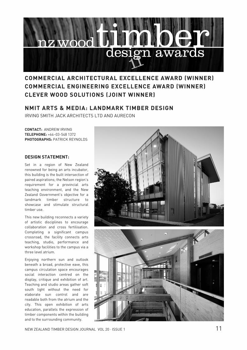
COMMERCIAL ARCHITECTURAL EXCELLENCE AWARD (WINNER) COMMERCIAL ENGINEERING EXCELLENCE AWARD (WINNER) CLEVER WOOD SOLUTIONS (JOINT WINNER) NMIT ARTS & MEDIA: LANDMARK TIMBER DESIGN IRVING SMITH JACK ARCHITECTS LTD AND AURECON
CONTACT: ANDREW IRVING TELEPHONE: +64–03-548 1372 PHOTOGRAPHS: PATRICK REYNOLDS
DESIGN STATEMENT:
Set in a region of New Zealand renowned for being an arts incubator, this building is the built intersection of paired aspirations; the Nelson region’s requirement for a provincial arts teaching environment, and the New Zealand Government’s objective for a landmark timber structure to showcase and stimulate structural timber use.
This new building reconnects a variety of artistic disciplines to encourage collaboration and cross fertilisation. Completing a significant campus crossroad, the facility connects arts teaching, studio, performance and workshop facilities to the campus via a three level atrium.
Enjoying northern sun and outlook beneath a broad, protective eave, this campus circulation space encourages social interaction centred on the display, critique and exhibition of art. Teaching and studio areas gather soft south light without the need for elaborate sun control and are readable both from the atrium and the city. This open exhibition of arts education, parallels the expression of timber components within the building and to the surrounding community.