Notes:1. Explosion proof for Class I Division 1Groups A, B, C, D; Class II Division 1Groups E, F, G; Class III2. Factory Sealed, conduit seal notrequired3. NACE MR0175 compliant4. NEMA 4X (IP67) ingress protection
4C TECHNOLOGIES PO #P7-1722-GCC
ARAMCO AREA CLASSIFICATION PHASE II
PIPELINE UPGRADE
BI-10-03096
NMR 602
19.00”482.6 mm
19.00”482.6 mm
1.72”43.69 mm
1.72”43.69 mm Acoustic Systems IncorporatedAcoustic Systems Incorporated
1 2 3 4 5 6 7 8 POWERPOWER
MASTER
TXD
CHANNEL TXDData BroadcasterData Broadcaster
Houston, Texas
1 2 3 4 5 6 7 8 MASTERMASTERDC PowerDC Power
PO
SP
OS
NE
G
EA
RT
H CHANNEL
5.25”133 mm
5.25”133 mm
FRONT VIEW
TOP VIEW
REAR VIEWREAR VIEW
NONE 1 1 900.2076-00 B
Acoustic Systems IncorporatedAcoustic Systems Incorporated
.XXX = .15+.XXX = .15+.XX = .4+.XX = .4+
.X = .8+.X = .8+MILLIMETERSMILLIMETERS
.XXX = .005+.XXX = .005+.XX = .015+.XX = .015+
.X = .03+.X = .03+INCHES1. TOLERANCE
OFSHEET
REV
SCALE
PART NUMBERPART NUMBER
TITLE
DATE
FINISH
MATERIAL
125FINISHFINISHSURFACE
AND SHARP EDGESAND SHARP EDGESREMOVE BURRSREMOVE BURRS
6. MACHINED INSIDE CORNERS .02 R MAX6. MACHINED INSIDE CORNERS .02 R MAX5. CONCENTRICITY .015 TIR.5. CONCENTRICITY .015 TIR.4. TOLERANCES ARE NON-ACCUMULATIVE.4. TOLERANCES ARE NON-ACCUMULATIVE.
INCHES (MILLIMETERS).INCHES (MILLIMETERS).3. ALL DIMENSIONS ARE IN INCHES OR3. ALL DIMENSIONS ARE IN INCHES OR
WAVEALERT VIII GPS AntennaWAVEALERT VIII GPS Antenna
31 JULY 200731 JULY 2007
5.0 in.
127 mm
6.12 in.
155 mm
BOTTOM VIEW
3/4 INCH
FEMALE NPT
For mounting on
pole or mast
NOTE:
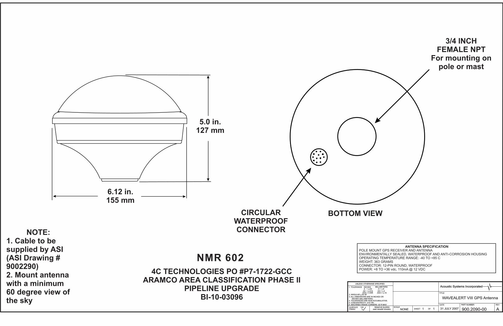
1. Cable to be
supplied by ASI
(ASI Drawing #
9002290)
2. Mount antenna
with a minimum
60 degree view of
the sky
ANTENNA SPECIFICATION
POLE MOUNT GPS RECEIVER AND ANTENNAENVIRONMENTALLY SEALED, WATERPROOF AND ANTI-CORROSION HOUSINGOPERATING TEMPERATURE RANGE: -40 TO +85 CWEIGHT: 363 GRAMSCONNECTOR: 12-PIN ROUND, WATERPROOFPOWER: +8 TO +36 vdc, 110mA @ 12 VDC
CIRCULAR
WATERPROOF
CONNECTOR
4C TECHNOLOGIES PO #P7-1722-GCC
ARAMCO AREA CLASSIFICATION PHASE II
PIPELINE UPGRADE
BI-10-03096
NMR 602
NONE 1 1 900.2110-00 A
Acoustic Systems IncorporatedAcoustic Systems Incorporated
.XXX = .15+.XXX = .15+.XX = .4+.XX = .4+
.X = .8+.X = .8+MILLIMETERSMILLIMETERS
.XXX = .005+.XXX = .005+.XX = .015+.XX = .015+
.X = .03+.X = .03+INCHES1. TOLERANCE
OFSHEET
REV
SCALE
PART NUMBERPART NUMBER
TITLE
DATE
FINISH
MATERIAL
125FINISHFINISHSURFACE
AND SHARP EDGESAND SHARP EDGESREMOVE BURRSREMOVE BURRS
6. MACHINED INSIDE CORNERS .02 R MAX6. MACHINED INSIDE CORNERS .02 R MAX5. CONCENTRICITY .015 TIR.5. CONCENTRICITY .015 TIR.4. TOLERANCES ARE NON-ACCUMULATIVE.4. TOLERANCES ARE NON-ACCUMULATIVE.
INCHES (MILLIMETERS).INCHES (MILLIMETERS).3. ALL DIMENSIONS ARE IN INCHES OR3. ALL DIMENSIONS ARE IN INCHES OR
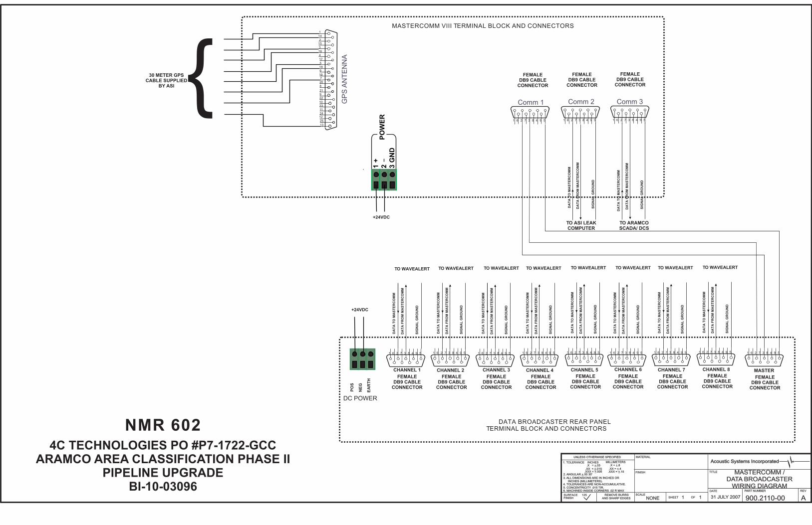
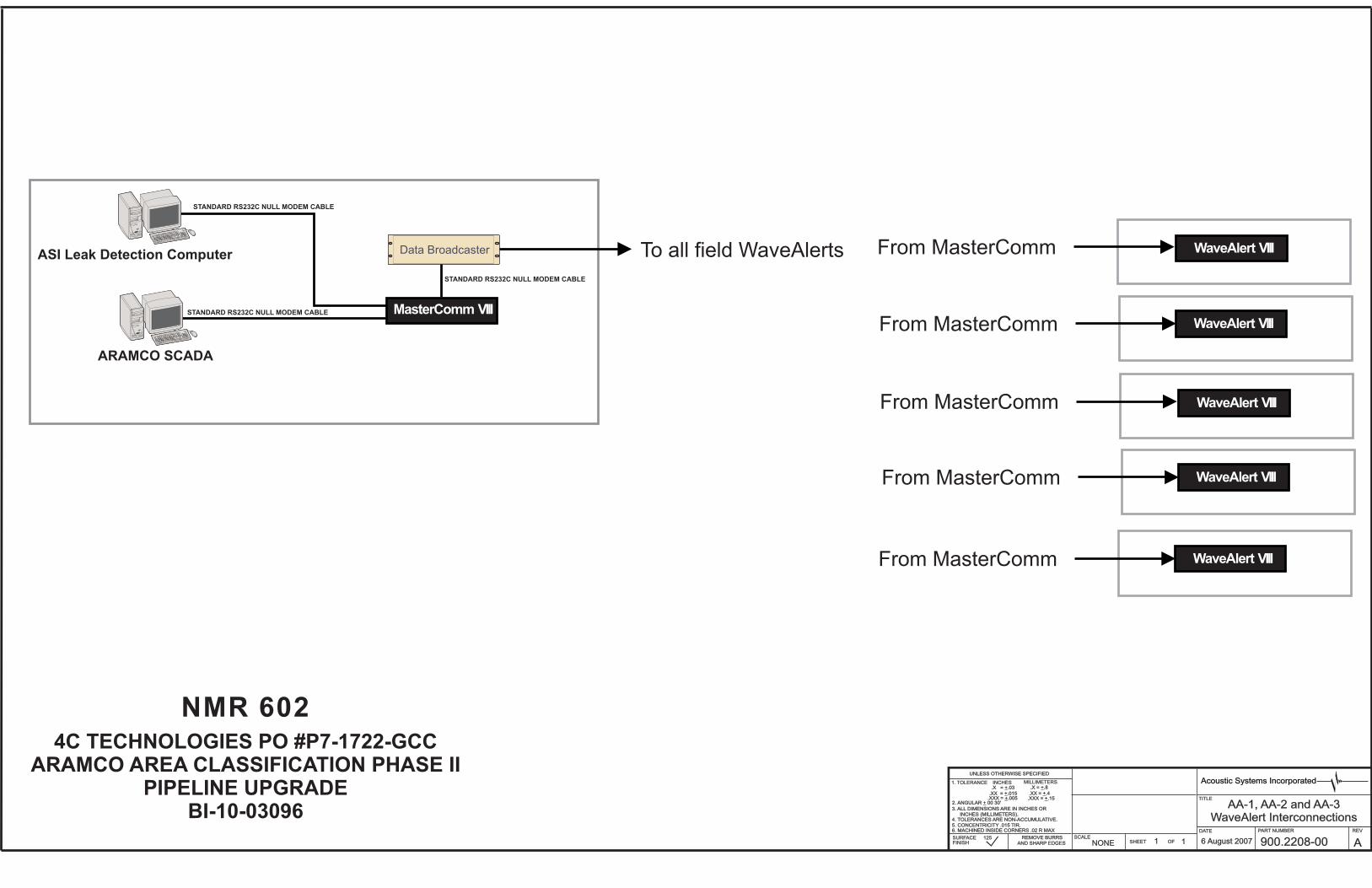
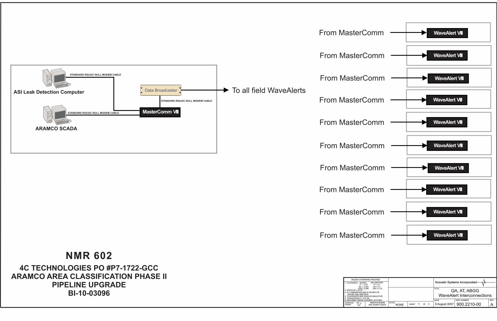
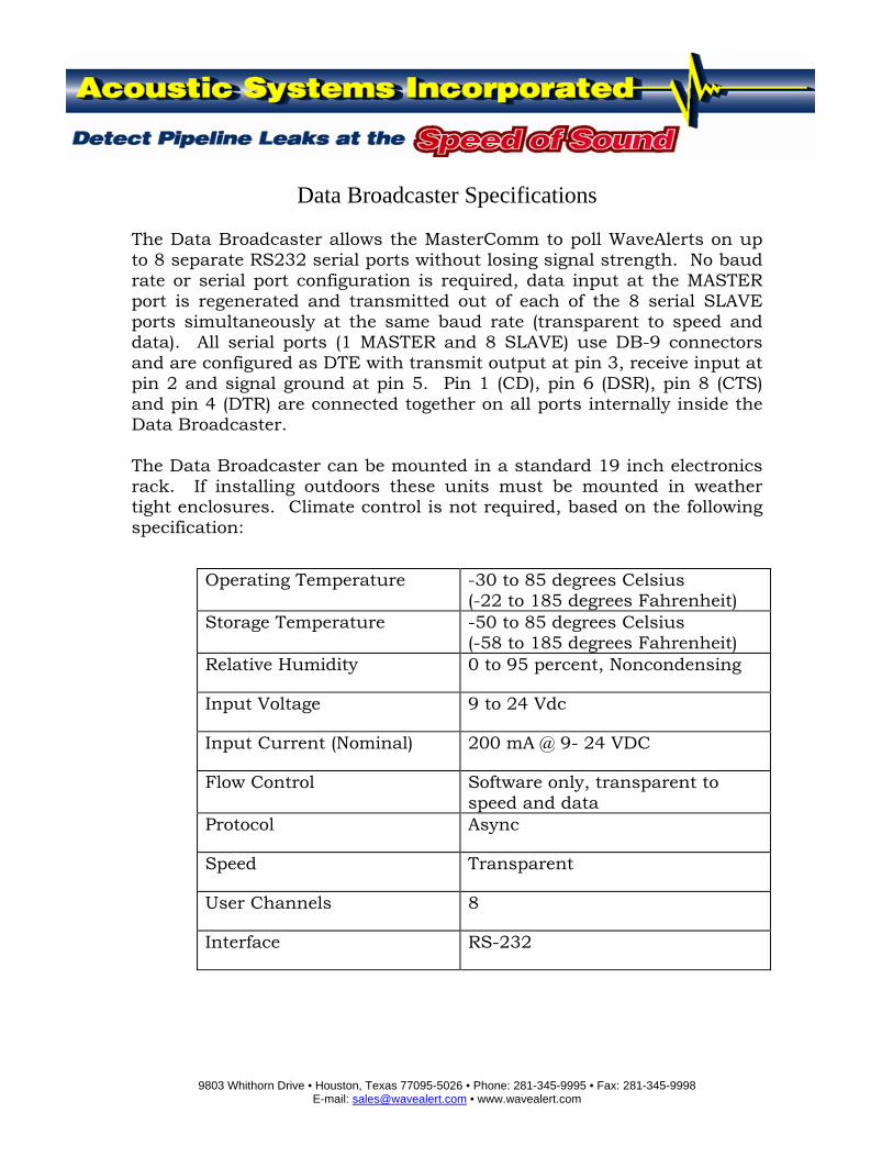
The Data Broadcaster allows the MasterComm to poll WaveAlerts on up to 8 separate RS232 serial ports without losing signal strength. No baud rate or serial port configuration is required, data input at the MASTER port is regenerated and transmitted out of each of the 8 serial SLAVE ports simultaneously at the same baud rate (transparent to speed and data). All serial ports (1 MASTER and 8 SLAVE) use DB-9 connectors and are configured as DTE with transmit output at pin 3, receive input at pin 2 and signal ground at pin 5. Pin 1 (CD), pin 6 (DSR), pin 8 (CTS) and pin 4 (DTR) are connected together on all ports internally inside the Data Broadcaster. The Data Broadcaster can be mounted in a standard 19 inch electronics rack. If installing outdoors these units must be mounted in weather tight enclosures. Climate control is not required, based on the following specification:
Operating Temperature -30 to 85 degrees Celsius (-22 to 185 degrees Fahrenheit)
Storage Temperature -50 to 85 degrees Celsius (-58 to 185 degrees Fahrenheit)
Relative Humidity 0 to 95 percent, Noncondensing
Input Voltage 9 to 24 Vdc
Input Current (Nominal) 200 mA @ 9- 24 VDC
Flow Control Software only, transparent to speed and data
Protocol Async
Speed Transparent
User Channels 8
Interface RS-232
June 07
S M T W TH F S 1 2
3 4 5 6 7 8 9
10 11 12 13 14 15 16
17 18 19 20 21 22 23
24 25 26 27 28 29 30
July 07
S M T W TH F S 1 2 3 4 5 6 7
8 9 10 11 12 13 14
15 16 17 18 19 20 21
22 23 23 25 26 27 27
29 30 31
August 07
S M T W TH F S 1 2 3 4
5 6 7 8 9 10 11
12 13 14 15 16 17 18
19 20 21 22 23 24 25
26 27 28 29 30 31
September 07
S M T W TH F S 1
2 3 4 5 6 7 8
9 10 11 12 13 14 15
16 17 18 19 20 21 22
23 24 25 26 27 28 29
30
October 07
S M T W TH F S 1 2 3 4 5 6
7 8 9 10 11 12 13
14 15 16 17 18 19 20
21 22 23 24 25 26 27
28 29 30 31
November 07
S M T W TH F S 1 2 3
4 5 6 7 8 9 10
11 12 13 14 15 16 17
18 19 20 21 22 23 24
25 26 27 28 29 30
December 07
S M T W TH F S 1
2 3 4 5 6 7 8
9 10 11 12 13 14 15
16 17 18 19 20 21 22
23 24 25 26 27 28 29
30 31
January 08
S M T W TH F S 1 2 3 4 5
6 7 8 9 10 11 12
13 14 15 16 17 18 19
20 21 22 23 24 25 26
27 28 29 30 31
February 08
S M T W TH F S 1 2
3 4 5 6 7 8 9
10 11 12 13 14 15 16
17 18 19 20 21 22 23
24 25 26 27 28 29
B I - 3 0 9 6 P R O J E C T S C H E D U L E
PROJECT PHASE START DATE END DATE
NMR 601 Drawings & Documentation 17 JUNE 07 31 JULY 07
NMR 602 Drawings and Documentation – Procurement 1 AUG 07 11 SEPT 07
Component Assembly 12 SEPT 07 30 NOV 07
Component Level Testing – System Assembly 1 DEC 07 12 JAN 08
Engineering and Full System Test 13 JAN 08 16 FEB 08
FAT – System Shipment 17 FEB 08 29 FEB 08
TQ11222000revF.doc Acoustic Systems Incorporated 1
Acoustic Systems Incorporated (ASI), a Houston, Texas based company, is an established leader in leak detection, with over twenty years experience in the development of quality hardware and software products.
ASI specializes in on-line real-time pipeline monitoring using acoustic techniques which provide unique advantages for pipeline leak detection, including:
Minimal time to detect and locate leaks, typically within one minute of leak occurrence
Very accurate leak location calculation, typically to within +/- 30 meters
Extremely low false alarm rate (typically less than one per year)
Used for most pressurized pipelines, including single phase liquid, single phase gas and multi-phase flow pipelines
Very sensitive, detect and locate very small leaks
Detect leaks with or without (shut-in) flow, steady state as well as various transient operations (valve open/close, pump shut down/startup, flow increase/decrease, etc.)
Very easy to install and operate
Continuous leak detection with loss of communications
Minimum maintenance, no calibration required
Used for automatic valve shut off upon detection of leak
Decreased risk to people and environment
Reduced financial loss for product and for clean-up in case of accidents
ASI’s Acoustic Leak Detection Systems (ALDS) employs proprietary hardware for on-line real-time leak detection and associated hardware and software for supervising communications, structuring databases, data analysis, decision-making, report and display generation and issuing alarms. Systems employ combinations of radio, fiber optic and hardwire communications with either personal or mainframe computers for operator interface. Applications include liquid, gas and multi-phase flow pipelines, and consist of single transmission lines, networks, gathering lines, subsea lines, single and multiple product transfer lines.
The WaveAlert® system is the only leak detection system with an establish record of not only detecting leaks but automatically shutting in pipeline valves to limit environmental damage and possible casualties. This can only be accomplished with a minimum number of false alarms. (See section 6.1 for a detailed example).
TQ11222000revF.doc Acoustic Systems Incorporated 2
1.1. Acoustic Systems Incorporated Taft Communications Systems Incorporated, pioneered acoustic leak detection monitoring technology for pipeline application; the direct forerunner of the ASI ALDS system. The first client was Tennessee Gas Pipeline Company.
Taft Communications was renamed Bethany International in 1973. In September 1978, Crutcher Resources Corporation purchased Bethany under a pooling of interests and Bethany became CRC Bethany International, Inc. Scientific Software Intercomp, a software company, purchased CRC Bethany in 1983. ASI was incorporated in the State of Texas in December 1983 and purchased the CRC Bethany Hardware Division (including patents, license agreements and inventory) on February 1, 1984.
Since 1984, ASI has worked continuously to keep hardware based monitoring techniques at the forefront of leak detection technology. ASI’s ALDS has been installed worldwide (Figure 1-1) on pipelines including gas, liquid and multi-phase flow.
Figure 1-1: Installations around the World with Various Pipelines
TQ11222000revF.doc Acoustic Systems Incorporated 3
1.2. Facilities ASI headquarters are located in Houston, Texas, USA, with a branch office in New Jersey and a network of marketing representatives covering the globe.
Mailing Address: Acoustic Systems Incorporated 9803 Whithorn Drive Houston, Texas 77095-5026, USA
TQ11222000revF.doc Acoustic Systems Incorporated 4
2. REAL TIME LEAK DETECTION _____________________________________________________________________________
2.1. Pipeline Monitoring Moving fluids by pipeline is an energy-efficient means of transportation, proven safe and effective over years of industry experience. In recent years, total mileage of installed pipelines has increased dramatically. This trend is expected to continue. A wide variety of fluids are transported by pipeline, including crude oil, natural gas, water and refined petroleum products. Many other liquid and gaseous industrial products, such as carbon monoxide, ammonia, phenol, cumene, acetone and copper slurry, are moved by pipeline.
Responsibility for a pipeline and its operations lies with the operator. Pipeline leaks are rare, but present serious problems when they occur. The most serious problem is the release of hazardous substance. Even if the release is not life threatening, there is concern over the effect of emissions on the environment and upon public image.
An unchecked leak represents loss of valuable product; clean up costs; increased hazard to life and environment; and cost to public image. The amount of product loss in a monitored pipeline depends upon:
Minimum detectable hole size
Elapsed time from leak to action
Additional costs include loss of service and repair expenses. The time required, to return a pipeline to service after a leak occurrence, can be greatly reduced by timely leak location information. The WaveAlert® Leak Detection System provides leak occurrence and location information quickly and accurately based upon direct measurements.
2.2. Leak Statistics The following statistics show causes of known worldwide pipeline failures for recent years.
Cause Percentage External Damage ................................... 58 % Material Failure ..................................... 18 % Corrosion .............................................. 15 % Construction Faults................................. 6 % Others ..................................................... 3 %
Table I: Causes of Known Pipeline Failures The majority of leaks are caused by third-party intervention, such as bulldozers, backhoes or theft. Additional causes include ground movement, earthquakes, corrosion and washouts under riverbeds. Material failures and improper operating procedures that cause damaging transient pressures or pressure surges have also been reported as causing leaks.
TQ11222000revF.doc Acoustic Systems Incorporated 5
Acoustic Leak Detection Systems (ALDS) are used on both liquid and gas pipelines as well as multi-phase flow pipelines to detect leaks quickly and provide a means of limiting product loss.
With over 20 years of worldwide applications, Acoustic Systems Incorporated (ASI) ALDS has proven to be the most effective, true real-time, on-line leak detection method. Acoustic Systems Incorporated has improved leak detection technology from many years of field proven applications providing the quickest leak detection, high sensitivity, precise leak location accuracy and low false alarm rate with minimum maintenance requirement. These improvements were made by developing and applying advanced data processing techniques such as differential filtering, moving average filtering, proprietary ‘SMART DRIVE’ for adaptive dynamic threshold adjustment, as well as various repetitive filters. One of these developments, the patented Signature Signal Matching Filter, is especially effective. The real-time signal is continuously compared against signature leak profiles for the particular operating and geometric conditions. These profiles were developed from a database established from over 20 years of experimental and field leak tests. This technique not only drastically reduces the false alarm rate (one alarm a year or less), but also significantly improves the sensitivity and leak location accuracy. This system will also detect leaks with shut-in flow (zero flow rate in the pipeline). With the use of GPS (Global Positioning System) it not only improves leak location accuracy, but also allows for continuous leak detection during the loss of communications.
3.1. System Configuration The WaveAlert® VIII ALDS is shown in Figure 3-1.
The ALDS includes three major assemblies and associated communications links:
WaveAlert® VIII Site Processor (including Acoustic Sensor Assembly)
MasterCommTM VIII Node Processor
ASI Leak Computer with SCADA Software
System operations are summarized in Figure 3-2.
TQ11222000revF.doc Acoustic Systems Incorporated 6
Figure 3-1: Schematic Diagram of the Acoustic Leak Detection System.
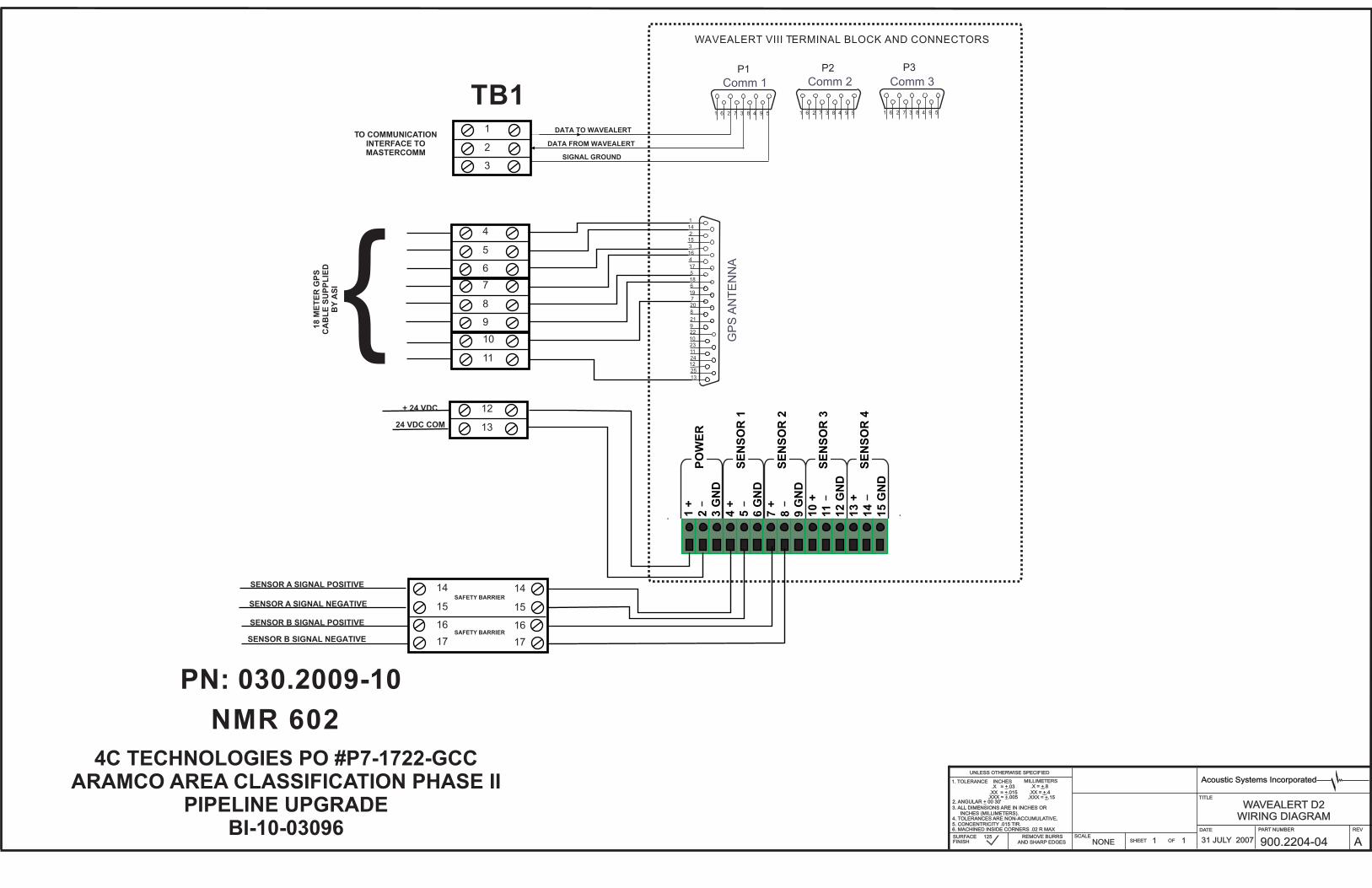
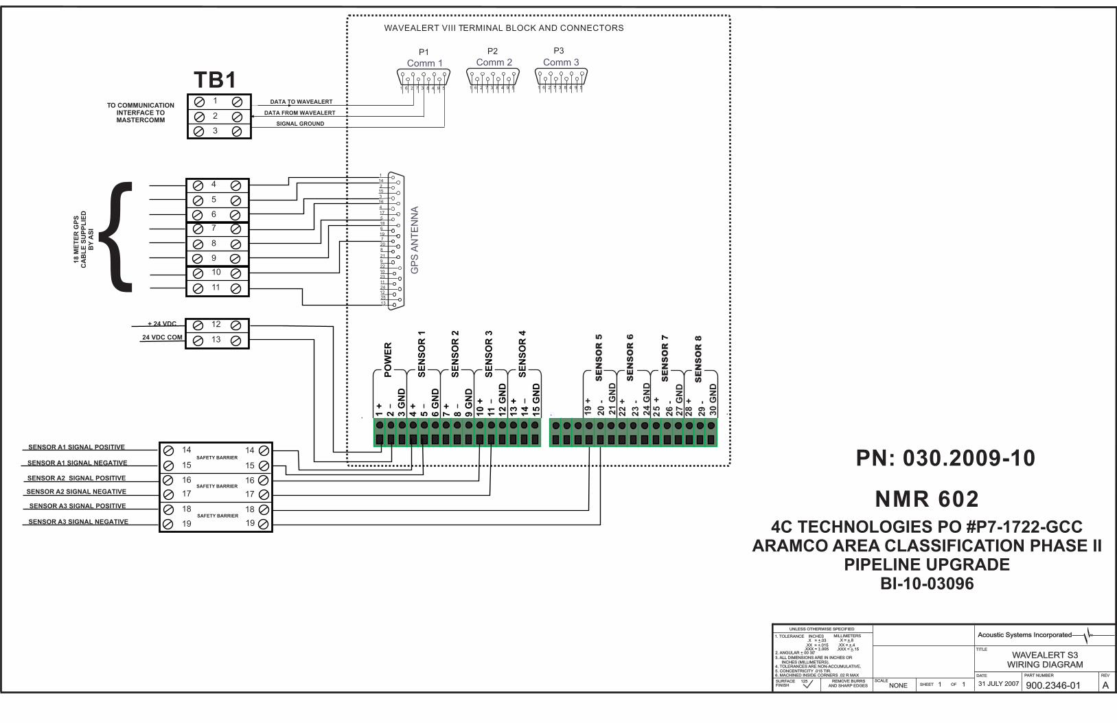
3.1.1. WaveAlert® VIII Site Processor and Acoustic Sensor Assembly The WaveAlert® VIII Site Processor and Acoustic Sensor Assembly are located along the pipeline (usually at valve sites or other designated locations) and comprise two separate assemblies.
The WaveAlert® VIII Site Processor monitors inputs from one or more acoustic sensors and distinguishes a leak signal from other pipeline noises.
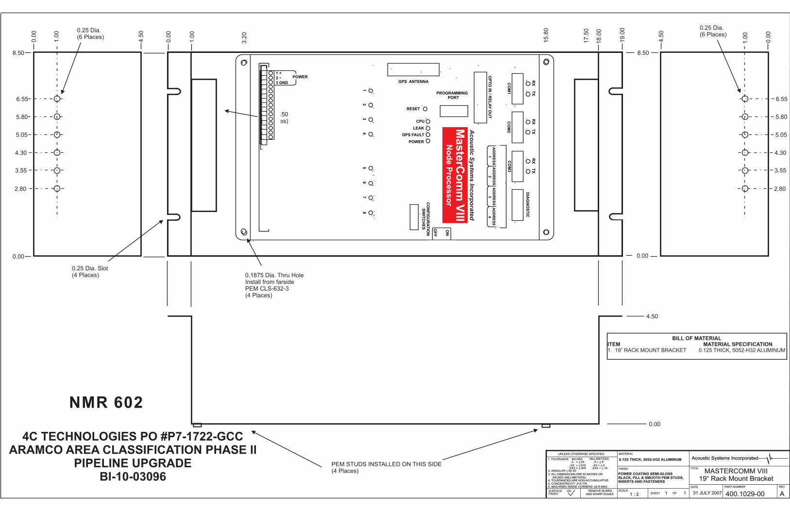
The WaveAlert® VIII Site Processor can be located within a standard 19-inch rack mount electronics cabinet and can be sited either in an equipment shelter, in a NEMA-3R (rain tight) enclosure or waterproof enclosure for underground installation.
3.1.2. MasterComm VIII Node Processor The MasterCommTM VIII Node Processor serves as the central processing unit for the ALDS. It polls WaveAlert® VIII Site Processors in turn. During each poll cycle, it stores digital and analog values including the time of any acoustic event registered. By comparing times of arrival of an acoustic event at two WaveAlert® VIII Site Processors, it determines if a leak has occurred, locates the
GPSReceiver
GPS Time Synchronization
A B
B
WaveAlert VII D2
WaveAlert VII S1
WaveAlert VII D2
MasterComm VII
Host Computer
B A
1
2
3
Zone 1
Zone 2
Zone 3
Protected Pipeline Section
TQ11222000revF.doc Acoustic Systems Incorporated 7
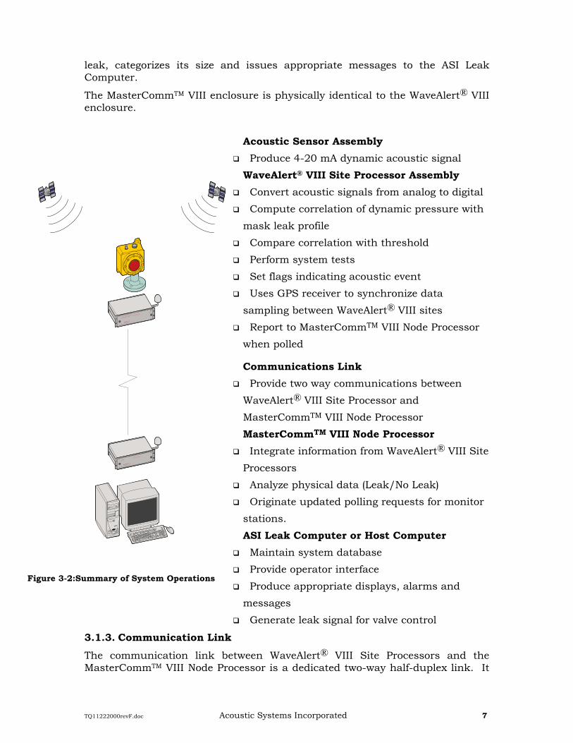
leak, categorizes its size and issues appropriate messages to the ASI Leak Computer.
The MasterCommTM VIII enclosure is physically identical to the WaveAlert® VIII enclosure.
Acoustic Sensor Assembly Produce 4-20 mA dynamic acoustic signal
WaveAlert® VIII Site Processor Assembly Convert acoustic signals from analog to digital
Compute correlation of dynamic pressure with
mask leak profile
Compare correlation with threshold
Perform system tests
Set flags indicating acoustic event
Uses GPS receiver to synchronize data
sampling between WaveAlert® VIII sites
Report to MasterCommTM VIII Node Processor
when polled
Communications Link Provide two way communications between
WaveAlert® VIII Site Processor and
MasterCommTM VIII Node Processor
MasterCommTM VIII Node Processor Integrate information from WaveAlert® VIII Site
Processors
Analyze physical data (Leak/No Leak)
Originate updated polling requests for monitor
stations.
ASI Leak Computer or Host Computer Maintain system database
Provide operator interface
Produce appropriate displays, alarms and
messages
Generate leak signal for valve control
3.1.3. Communication Link The communication link between WaveAlert® VIII Site Processors and the MasterCommTM VIII Node Processor is a dedicated two-way half-duplex link. It
Figure 3-2:Summary of System Operations
TQ11222000revF.doc Acoustic Systems Incorporated 8
11.75"
298.50 mm
0.62"
15.75 mm
10.50"
266.70 mm
0.70"
17.80 mm
DrawerClearanceRequired
19.00"
482.6 mm
Front View
Rear View
5.22"
132.5 mm 2.25"
57.15 mm
0.25"
6.35 mm
18.31"
465.1 mm
0.28"
7.1 mm
1. Access to rear panel is required for wiring connections, power switch and DB connectors.2. Approximate total weight (with all circuit boards included) is 20lbs. (9kg).
Notes:
may include radio, hardwire landline, fiber optic sections or any other dedicated communication links.
3.1.4. ASI Leak Computer and SCADA Software The ASI Leak Computer with SCADA Software provides user interface with the ALDS via Video Screens, Keyboard, Audio Alarms and Printer. ASI can provide either a turnkey system featuring a Personal Computer with SCADA software or provide a detailed interface specification to permit interface to a mainframe computer with SCADA software.
Figure 3-3: Outline Drawing of the WaveAlert® VIII Site Processor and MasterCommTM VIII Node Processor Enclosures.
3.1.5. WaveAlert® VIII and MasterCommTM VIII Hardware The WaveAlert® VIII Site Processor and the MasterCommTM VIII Node Processor incorporate advanced signal processing hardware.
The WaveAlert® VIII Site Processor uses the following circuits:
TQ11222000revF.doc Acoustic Systems Incorporated 9
14.00"
355.6 mm
2" Flange Mounted
Transducer Assembly
Provided by ASI
5.75"146 mm
Center-to-center
7.00"178 mm
End-to-end
8.50"
216.0 mm
7.50"
191.0 mm
5.75"
146.0 mm
2" Gate Valve
Customer Supplied
600 # 2" Raised
Face Flange
0.406 Diameter (10 mm)
Micarta Isolation Gasket
Complete with Fastener Isolation
Flange Fasteners .75 inch (19 mm)
Diameter Customer Supplied
2" Main Line Tap
Main Line
1. Enclosure is rated NEMA -72. Approximate total weight of the Transducer Assembly provided by ASI is 40 lbs. (18.14 kg)
Notes:
Power Supply Circuit
Signal Processor Circuit
Signal Conditioner Circuit
Interface Status I/O Circuit
Figure 3-4: Outline Drawing of the Acoustic Sensor Assembly The MasterCommTM VIII Node Processor uses the following circuits:
Power Supply
Signal Processor Circuit
Interface Status I/O Circuit
TQ11222000revF.doc Acoustic Systems Incorporated 10
3.1.5.1. Power Supply Circuit The Power Supply consists of an advanced switch-mode DC/DC converter, which accepts raw DC input and generates required system voltages. Input to output isolation of 500 VDC is provided, as well as output current limiting, automatic restart, and input transient suppression.
3.1.5.2. Signal Processor Circuit The Signal Processor Circuit is the central control subsystem of the Site and Node Processors. It consists of a signal processor with associated clock, interface and memory circuits. It generates control and timing signals, provides communication oversight, provides digital filtering to discriminate against noise caused by pumps, opening or closing of valves, or other normal pipe operations and performs internal self tests to assure proper system operation. This also consists of various ASI patented proprietary data processing algorithm
3.1.5.3. Signal Conditioner Circuit The primary functions of the Signal Conditioner Circuit are galvanic isolation and filtering of signals from the Acoustic Sensor Assembly.
3.1.5.4. Interface Status I/O Circuit The Interface Status I/O Circuit allows the WaveAlert® VIII to perform application specific tasks. Inputs include four optically isolated status inputs. Output include four, 2 ampere, dry, NO/NC contacts.
3.1.6. ASI Leak Computer The ASI Leak Computer may be either a dedicated personal computer for smaller systems or a mini-computer (which may timeshare). The ASI Leak Computer communicates with one or more MasterCommTM VIII Node Processors. Usually this is via direct connection conforming to the RS-232C standard.
3.2. Measuring Techniques 3.2.1. Directional Dual Element Acoustic Sensor Arrays In a typical installation, it is often necessary to locate acoustic sensors near pumping stations and active flow control valves; usually sites of high noise levels. To discriminate against this off line noise, directional acoustic sensor arrays consisting of two acoustic-sensing elements separated by a distance of 50 to 100 meters (165 to 328 ft) are used at the ends of protected pipeline sections.
This dual element sensor array forms a directional filter, rejecting noise from one direction, but detecting a signal from the other.
The WaveAlert® VIII S1 Site Processor employs a single acoustic sensor, sensitive to acoustic signals originating from either direction. This configuration is used at intermediate locations along the pipeline, away from compressor stations, control valves, etc.
TQ11222000revF.doc Acoustic Systems Incorporated 11
MasterComm VII
WaveAlert VII D2
V
t 1
t 2
A B
B
WaveAlert VII S1
GPSReceiver
1
2
Host Computer
SD
S = D + 1 (t 1 - t 2) V_ _
2 2
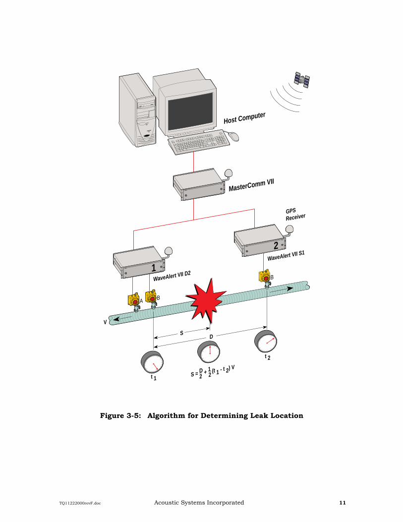
Figure 3-5: Algorithm for Determining Leak Location
TQ11222000revF.doc Acoustic Systems Incorporated 12
3.2.2. Leak Location Leak Location is determined from times of arrival of the acoustic signal at two adjacent WaveAlert® VIII acoustic sensors. Figure 3-5 shows the algorithm for the case of a single product in the pipeline between sites. The rupture occurs at time t = 0 shown by the middle clock. The signal travels away from the leak in both directions and arrives at the acoustic sensors at later times. If the rupture is farther from site 1 than site 2, clock 1 runs longer than clock 2.
The leak location, S, is measured from site 1. D is the distance between sites.
Notice that if t1 = t2, according to the location algorithm, the leak is located at the midpoint of the pipeline segment. If t1 < t2,, the leak is located left of the midpoint.
3.2.3. Leak Declaration Leak declaration decisions, are made by the MasterCommTM VIII Node Processor from information, supplied by WaveAlert® VIII Site Processors. Decisions are based upon requirements that:
More than one WaveAlert® VIII Site Processor recorded an acoustic event
The acoustic signal source is found to originate at a location on the protected segment of the pipeline
The potential leak event signals received from two or more local Wavealert® Processors are verified by proprietary data processing and identification algorithm at the MasterCommTM.
Figure 3-6: Muting Zones Adjacent to Wavealert® VIII Sites
GPSReceiver
GPS Time Synchronization
A B
B
WaveAlert VII D2
WaveAlert VII S1
WaveAlert VII D2
MasterComm VII
Host Computer
B A
1
2
3
Zone 1
Zone 2
Zone 3
Protected Pipeline Section
TQ11222000revF.doc Acoustic Systems Incorporated 13
3.2.4. Muting Zones Noise from sources located beyond the ends of the protected section of the pipeline which result in acoustic event declarations by more than one WaveAlert® VIII Site Processor will be determined to be within the leak location accuracy from the near acoustic sensor. Since the majority of false event declarations are produced by off line acoustic sources, the false leak alarm rate is greatly reduced, if acoustic signals observed outside of the protected zone can be excluded. However, due to the uncertainty associated with location calculation, a muting zone is declared on either side of each acoustic sensor within which that WaveAlert® VIII is not allowed to contribute data leading to a leak declaration (See Figure 3-6.) Thus, at the ends of the pipeline, protection is not afforded for a short distance (determined by the leak location accuracy) from the B transducer. At intermediate WaveAlert® VIII sites, even though the local WaveAlert® VIII cannot contribute to a leak decision for leak signals originating within its muting zone, one active WaveAlert® VIII located on either side can contribute data for a decision. Thus, protection is provided at intermediate sites.
3.2.5. Detection Time The maximum time required to detect a leak is the sum of:
Travel time for an acoustic signal from the leak site to the farthest monitor site, equal to the distance between adjacent monitor sites divided by acoustic velocity in the pipeline medium.
Time for the Node Processor to poll all Site Processors twice and compute leak location. Scan time includes communications delays such as radio keying time.
Typical time of detecting and locating leak ranges from 10 seconds to 1 minute.
3.2.6. System Performance Minimum detectable leak size depends upon several factors, which include:
Static pressure in the pipeline
Distance of the WaveAlert® VIII from the leak
Pipe diameter and wall thickness
Background noise levels of the pipeline
Fluid properties
The leak threshold setting of a WaveAlert® VIII Site Processor depends upon the typical noise level in the pipeline during normal operation and the signal-to-noise ratio required to achieve a satisfactory false alarm rate. These factors depend upon the design and operation of the pipeline. ASI performs a sensitivity analysis of the line to determine the minimum detectable theoretical leak size, location accuracy, maximum detecting time and optimum placement of WaveAlert® VIII Site Processors on the pipeline. A data sheet for data used to perform this sensitivity analysis is enclosed in the Appendix of this document.
TQ11222000revF.doc Acoustic Systems Incorporated 14
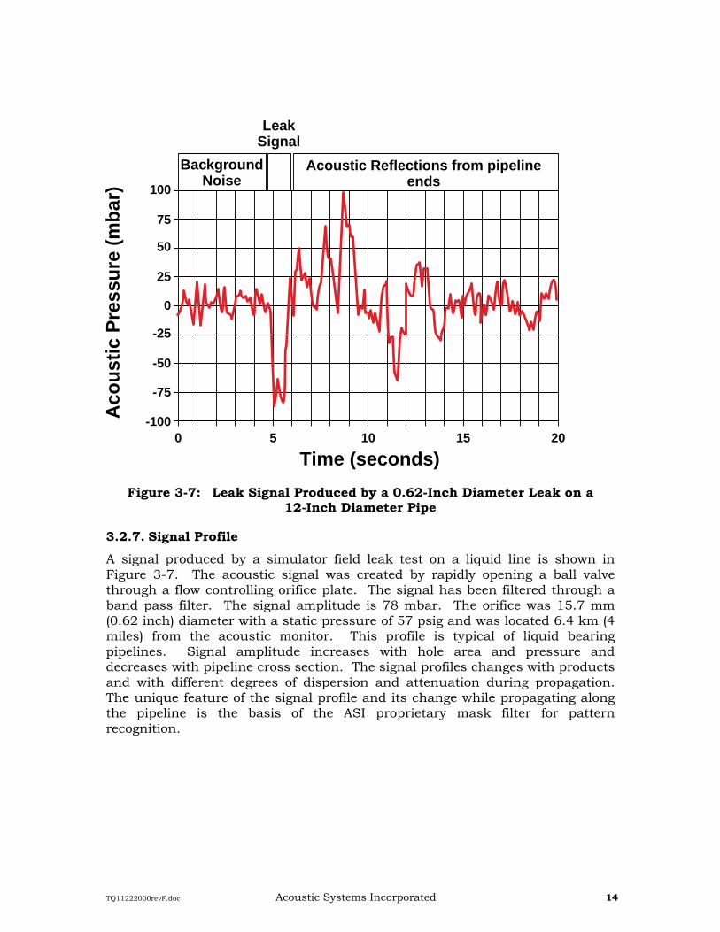
Figure 3-7: Leak Signal Produced by a 0.62-Inch Diameter Leak on a 12-Inch Diameter Pipe
3.2.7. Signal Profile A signal produced by a simulator field leak test on a liquid line is shown in Figure 3-7. The acoustic signal was created by rapidly opening a ball valve through a flow controlling orifice plate. The signal has been filtered through a band pass filter. The signal amplitude is 78 mbar. The orifice was 15.7 mm (0.62 inch) diameter with a static pressure of 57 psig and was located 6.4 km (4 miles) from the acoustic monitor. This profile is typical of liquid bearing pipelines. Signal amplitude increases with hole area and pressure and decreases with pipeline cross section. The signal profiles changes with products and with different degrees of dispersion and attenuation during propagation. The unique feature of the signal profile and its change while propagating along the pipeline is the basis of the ASI proprietary mask filter for pattern recognition.
BackgroundNoise
Acoustic Reflections from pipelineends
LeakSignal
Aco
ust
ic P
ress
ure
(m
bar
)
Time (seconds)0 5 10 15 20
-100
-75
-50
-25
0
25
50
75
100
TQ11222000revF.doc Acoustic Systems Incorporated 15
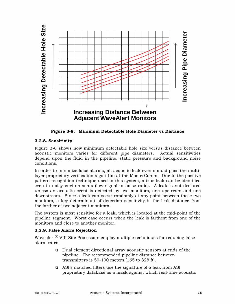
Figure 3-8: Minimum Detectable Hole Diameter vs Distance
3.2.8. Sensitivity Figure 3-8 shows how minimum detectable hole size versus distance between acoustic monitors varies for different pipe diameters. Actual sensitivities depend upon the fluid in the pipeline, static pressure and background noise conditions.
In order to minimize false alarms, all acoustic leak events must pass the multi-layer proprietary verification algorithm at the MasterComm. Due to the positive pattern recognition technique used in this system, a true leak can be identified even in noisy environments (low signal to noise ratio). A leak is not declared unless an acoustic event is detected by two monitors, one upstream and one downstream. Since a leak can occur randomly at any point between these two monitors, a key determinant of detection sensitivity is the leak distance from the farther of two adjacent monitors.
The system is most sensitive for a leak, which is located at the mid-point of the pipeline segment. Worst case occurs when the leak is farthest from one of the monitors and close to another monitor.
3.2.9. False Alarm Rejection Wavealert® VIII Site Processors employ multiple techniques for reducing false alarm rates:
Dual element directional array acoustic sensors at ends of the pipeline. The recommended pipeline distance between transmitters is 50-100 meters (165 to 328 ft).
ASI’s matched filters use the signature of a leak from ASI proprietary database as a mask against which real-time acoustic
TQ11222000revF.doc Acoustic Systems Incorporated 16
signals data compared. The ASI proprietary database was built over twenty years of efforts compiling from both field leak data as well as experimental leak test data for various pipeline operating conditions and different transporting fluids. This allows a fingerprint matching type of positive identification on the true leak signal and drastically reduces the possibility of false alarm and increases the detection sensitivity.
Digital high pass and low pass filters with adjustable roll-off frequencies.
Moving average filter to suppress higher frequency noise.
Dynamic threshold logic utilizes the ASI proprietary “SMART DRIVE’ auto-adjust mechanism in distinguishing abnormal noise from true leak signals. The ASI ‘SMART DRIVE’ program continuously scans, computes, and verifies all incoming data and automatically adjusts the dynamic thresholds based on the ASI proprietary expert logic developed over years of experiences. This will further reduce the false alarm rate.
Repetitive Filters to suppress cyclic pipeline noise and other various unusual noise sources.
False alarm rate is also a function of frequency of activity (sudden pressure changes on the pipeline associated with operating changes and background noise.) By use of the above filters false alarms have been reduced significantly. The false alarm frequency is expected to be less than three per year (typically less than one per year) for a commissioned system.
3.3. Available Configurations The WaveAlert® VIII D Site Processor is configured to monitor one or two dual element, directional sensor arrays at the end of a protected pipeline segment. The WaveAlert® VIII S Site Processor monitors one or two single element sensors.
Site Processor configurations are summarized in Table II. The last number in the designation is the total number of sensor elements supported.
Designation Sensor Configuration Total Number of Sensor Elements WaveAlert® VIII S1 Single sensor....................................... 1 WaveAlert® VIII D2 Directional sensor array ...................... 2 WaveAlert® VIII S2 Two single sensors * ............................ 2 WaveAlert® VIII D4 Two directional sensor arrays ............. 4 WaveAlert® VIII D3 One single sensor One directional sensor array* .............. 3 WaveAlert® VIII SR1 Single sensor, remote Wavealert® processor * For monitoring parallel lines
Table II: Available Configurations for WaveAlert® VIII Site Processors.
TQ11222000revF.doc Acoustic Systems Incorporated 17
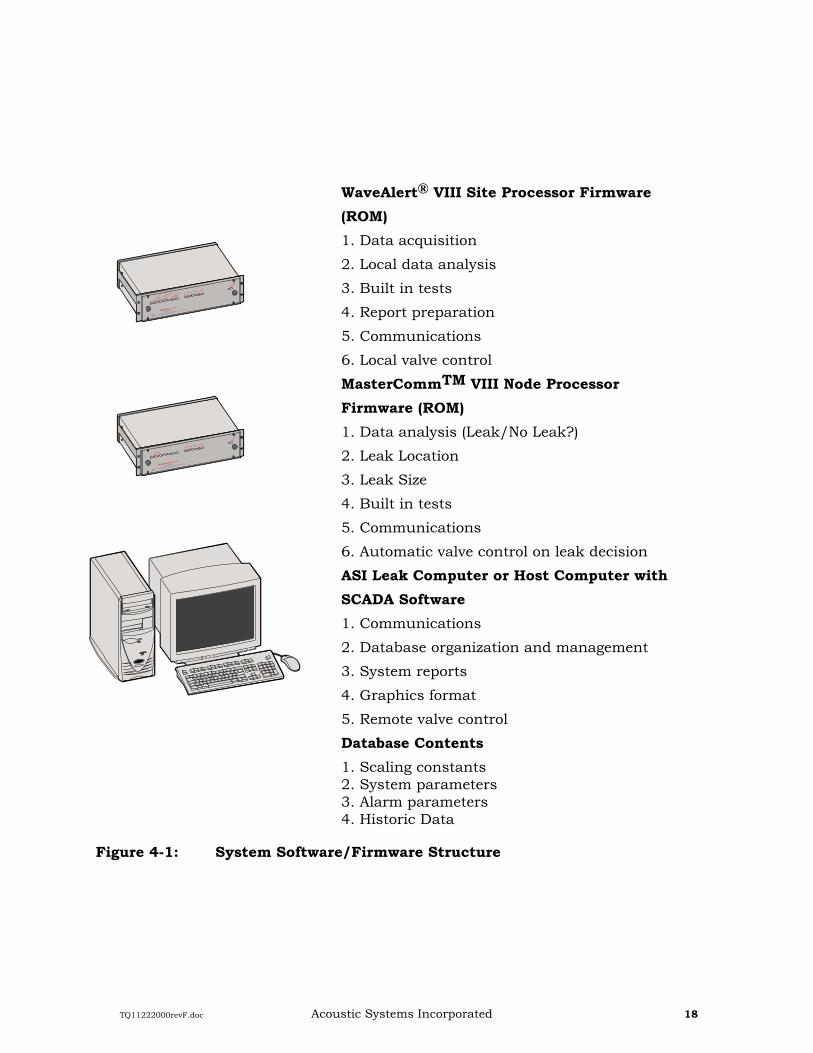
The WaveAlert® VIII Leak Detection System employs three basic software/firmware systems. Software/firmware tasks within these systems are shown in Figure 4.1.
4.1. WaveAlert® VIII Site Processor Firmware Site Processor instructions are supplied in ROM and contain local operating instructions for the WaveAlert® VIII including data gathering, housekeeping, first line data processing and analysis, decision making, communications and self-test instructions.
4.2. MasterCommTM VIII Node Processor Firmware MasterCommTM VIII Node Processor Firmware provides instructions for communications with Site Processors, data storage, data processing and analysis decision-making (leak vs no leak, leak location and size), self-tests and communications with the ASI Leak Computer. Node Processor firmware is configured specifically to each installation.
4.3. SCADA SCADA software residing in the ASI Leak Computer includes: information and communications management instructions for transfer of data between the ASI Leak Computer and MasterCommTM VIII Node Processor(s), database management information and instructions for the organization, maintenance and security of the system, historical (operating) information, instructions concerning organization and content of printed reports; and format and contents of graphic displays.
The system database maintained under SCADA contains scaling constants to convert binary numbers to engineering values (psig, mbar, etc.), system operating parameters (alarm threshold values, digital filter parameters, etc., which are downloaded to the MasterCommTM VIII Node Processor and hence to individual WaveAlert® VIII Site Processors and historical information (times, pressure values, flag settings, flag clearings, events declared, etc.)
Leak Event reports are displayed on the ASI Leak Computer terminal and printed, whenever, an event flag is set by any WaveAlert® VIII Site Processor. A representative display is shown in Figure 4-2. Other printed system reports can be provided daily, displaying system parameters, performance summaries, etc.
TQ11222000revF.doc Acoustic Systems Incorporated 18
WaveAlert® VIII Site Processor Firmware (ROM) 1. Data acquisition
2. Local data analysis
3. Built in tests
4. Report preparation
5. Communications
6. Local valve control
MasterCommTM VIII Node Processor Firmware (ROM) 1. Data analysis (Leak/No Leak?)
2. Leak Location
3. Leak Size
4. Built in tests
5. Communications
6. Automatic valve control on leak decision
ASI Leak Computer or Host Computer with SCADA Software 1. Communications
2. Database organization and management
3. System reports
4. Graphics format
5. Remote valve control
Database Contents 1. Scaling constants 2. System parameters 3. Alarm parameters 4. Historic Data
Figure 4-1: System Software/Firmware Structure
TQ11222000revF.doc Acoustic Systems Incorporated 19
Figure 4-2: Representative Leak Display at ASI Leak Computer
TQ11222000revF.doc Acoustic Systems Incorporated 20
5. SYSTEMS _____________________________________________________________________________
Typical ALDS installations are shown on the following pages.
Figure 5-1 shows an installation consisting of two WaveAlert® VIII D2 (dual element sensor array) Site Processors on a single pipeline segment. Dual sensor directional arrays are used to attenuate noise entering the pipeline at the ends of the protected segment. The WaveAlert® VIII D2 Site Processors communicate with the MasterCommTM VIII Node Processor either via dedicated landlines or by half duplex radio link. One MasterCommTM VIII Node Processor can monitor up to twenty Site Processors, collecting and analyzing system data and communicating with the ASI Leak Computer. Multiple MasterCommTM VIII Node Processors can be used for larger systems.
Figure 5-1: Two WaveAlert® VIII D2 Site Processors Monitoring a Simple Pipeline
Figure 5-2 shows a similar system in which the personal computer communicates with a central mainframe computer via a secondary communication link, permitting centralized monitoring of multiple Leak Detection Systems and providing data for a permanent record as part of an integrated risk management program.
Figure 5-3 shows a long transmission line. WaveAlert® VIII D2 Site Processors with directional sensor arrays are located at ends of the monitored pipeline segment near compressor stations or other sources of acoustic noise. WaveAlert® VIII S1 Site Processors with sensors at intermediate block valve sites provide fail-safe shut-in valve control in case of need. The system uses a
GPSReceiver
A B
B A
Host Computer
GPS Time Synchronization
1
2
WaveAlert VII D2
Site Processor
WaveAlert VII D2
Site Processor
MasterComm VII
Node Processor
TQ11222000revF.doc Acoustic Systems Incorporated 21
combination of radio links and landlines for communication between WaveAlert® VIII Site Processors and MasterCommTM VIII Node Processor.
Figure 5-2: ASI Leak Computer Communicating With A Central Main Frame Computer
Figure 5-3: WaveAlert® VIII Monitoring a Transmission Line
GPSReceiver
WaveAlert VII D2
A B
Main Line
MasterComm VII
Host Computer
WaveAlert VII D2
B A1
2
Central
Mainframe
Computer
GPS Time Synchronization
GPSReceiver
GPS Time Synchronization
WaveAlert VII D2
A B
B
B
WaveAlert VII S1WaveAlert VII S1
WaveAlert VII S1
Main Line
MasterComm VII
Host Computer
WaveAlert VII D2
B
B A
12
34
5
TQ11222000revF.doc Acoustic Systems Incorporated 22
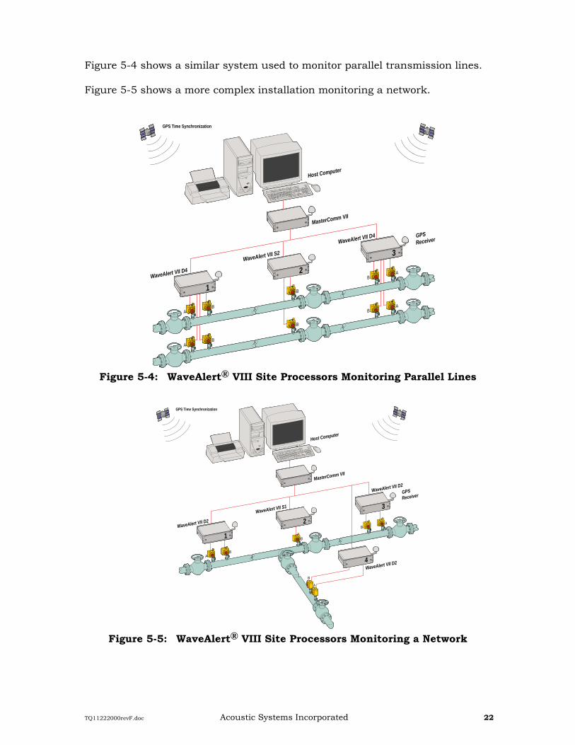
Figure 5-4 shows a similar system used to monitor parallel transmission lines. Figure 5-5 shows a more complex installation monitoring a network.
Figure 5-4: WaveAlert® VIII Site Processors Monitoring Parallel Lines
Figure 5-5: WaveAlert® VIII Site Processors Monitoring a Network
GPSReceiver
GPS Time Synchronization
AB
B
BA
AB
B
WaveAlert VII D4
WaveAlert VII S2
WaveAlert VII D4
MasterComm VII
Host Computer
BA
1
2
3
GPSReceiver
GPS Time Synchronization
AB
B
WaveAlert VII D2
WaveAlert VII S1
WaveAlert VII D2MasterComm VII
Host Computer
B
B
A
A
1
2
3
WaveAlert VII D24
TQ11222000revF.doc Acoustic Systems Incorporated 23
6. TYPICAL INSTALLATIONS AND APPLICATIONS _____________________________________________________________________________
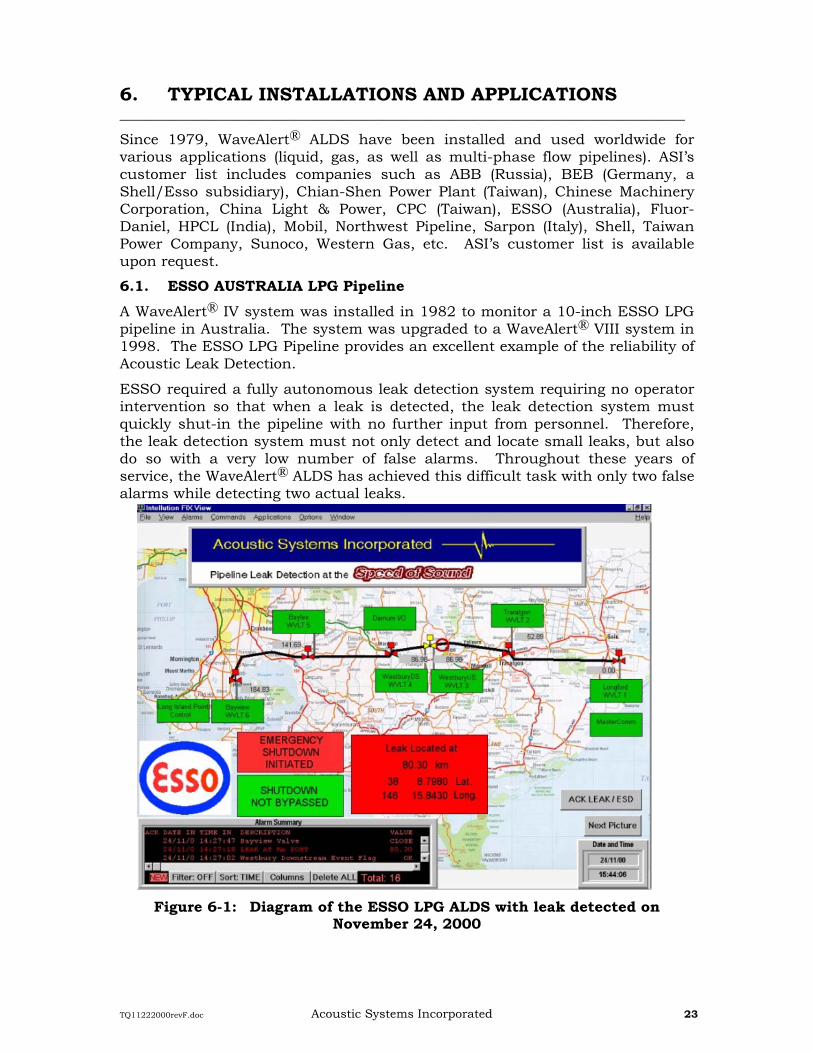
Since 1979, WaveAlert® ALDS have been installed and used worldwide for various applications (liquid, gas, as well as multi-phase flow pipelines). ASI’s customer list includes companies such as ABB (Russia), BEB (Germany, a Shell/Esso subsidiary), Chian-Shen Power Plant (Taiwan), Chinese Machinery Corporation, China Light & Power, CPC (Taiwan), ESSO (Australia), Fluor-Daniel, HPCL (India), Mobil, Northwest Pipeline, Sarpon (Italy), Shell, Taiwan Power Company, Sunoco, Western Gas, etc. ASI’s customer list is available upon request.
6.1. ESSO AUSTRALIA LPG Pipeline A WaveAlert® IV system was installed in 1982 to monitor a 10-inch ESSO LPG pipeline in Australia. The system was upgraded to a WaveAlert® VIII system in 1998. The ESSO LPG Pipeline provides an excellent example of the reliability of Acoustic Leak Detection.
ESSO required a fully autonomous leak detection system requiring no operator intervention so that when a leak is detected, the leak detection system must quickly shut-in the pipeline with no further input from personnel. Therefore, the leak detection system must not only detect and locate small leaks, but also do so with a very low number of false alarms. Throughout these years of service, the WaveAlert® ALDS has achieved this difficult task with only two false alarms while detecting two actual leaks.
Figure 6-1: Diagram of the ESSO LPG ALDS with leak detected on November 24, 2000
TQ11222000revF.doc Acoustic Systems Incorporated 24
6.1.1. System Configuration Six WaveAlert® VIII site processors are used to monitor the 188 km pipeline. The system is configured to monitor valve status and provide independent pressure measurements from each WaveAlert® site. Each WaveAlert® Site Processor controls an isolation valve. With control of isolation valves the WaveAlert® system will automatically shut-in the pipeline when a leak is detected without any human intervention.
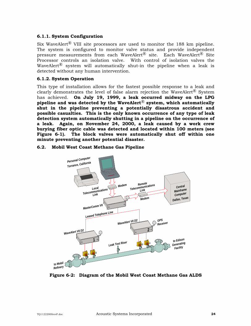
6.1.2. System Operation This type of installation allows for the fastest possible response to a leak and clearly demonstrates the level of false alarm rejection the WaveAlert® System has achieved. On July 19, 1999, a leak occurred midway on the LPG pipeline and was detected by the WaveAlert® system, which automatically shut in the pipeline preventing a potentially disastrous accident and possible casualties. This is the only known occurrence of any type of leak detection system automatically shutting in a pipeline on the occurrence of a leak. Again, on November 24, 2000, a leak caused by a work crew burying fiber optic cable was detected and located within 100 meters (see Figure 6-1). The block valves were automatically shut off within one minute preventing another potential disaster. 6.2. Mobil West Coast Methane Gas Pipeline
Figure 6-2: Diagram of the Mobil West Coast Methane Gas ALDS
GPSReceiver
Modem
Modem
WaveAlert VII D2
A B
WaveAlert VII D2
MasterComm VII
B A1
2
Leak Test Riser
Leased Telephone Line
to Edison
Generating
Facility
to Mobil
Refinery
Personal Computer
Torrance, California
Remote
Telecommunications
LinkLocal
Telecommunications
Link
Central
Mainframe
Computer
Dallas, Texas
TQ11222000revF.doc Acoustic Systems Incorporated 25
6.2.1. System Configuration ASI Acoustic Leak Detection monitors are installed on a Mobil West Coast 14 inch methane gas pipeline. The line is 2.85 miles long and protected by WaveAlert® VIII Site Processors at each end. The pressure of the gas in the line is about 75 psi, with a flow rate of 3800 Mscf/hour. The confirmation of a leak event is performed by proprietary firmware residing on the MasterComm TM VIII and displayed on the central mainframe computer video terminal located at Dallas, Texas. It is critical that any occurrence of a leak on this segment be detected and located within seconds, due to the hazardous nature of the product.
6.2.2. System Performance Tests, using standard leak test procedures, were conducted to establish threshold settings, verify the sensitivity of the system, confirm the acoustic velocity in this particular pipeline and the time required to detect and locate the leak.
Leaks were simulated in the line at a leak site located 1.43 miles from the refinery end of the line (see Figure 6-2). A two-inch ball valve in series with an orifice plate was used in the tests. Several tests with different orifice sizes were conducted. The sensitivity of the system under average flow conditions was determined to be well within specified performance. The system displayed accurate leak locations within 53 feet of each leak test.
Detection-time, also was determined. All leaks were detected within 7 seconds at the refinery end. A leak occurring at one end of the segment is detectable at the other end within 13 seconds. (Detection time and leak location accuracy improves as the leak occurs closer to the midpoint of the line).
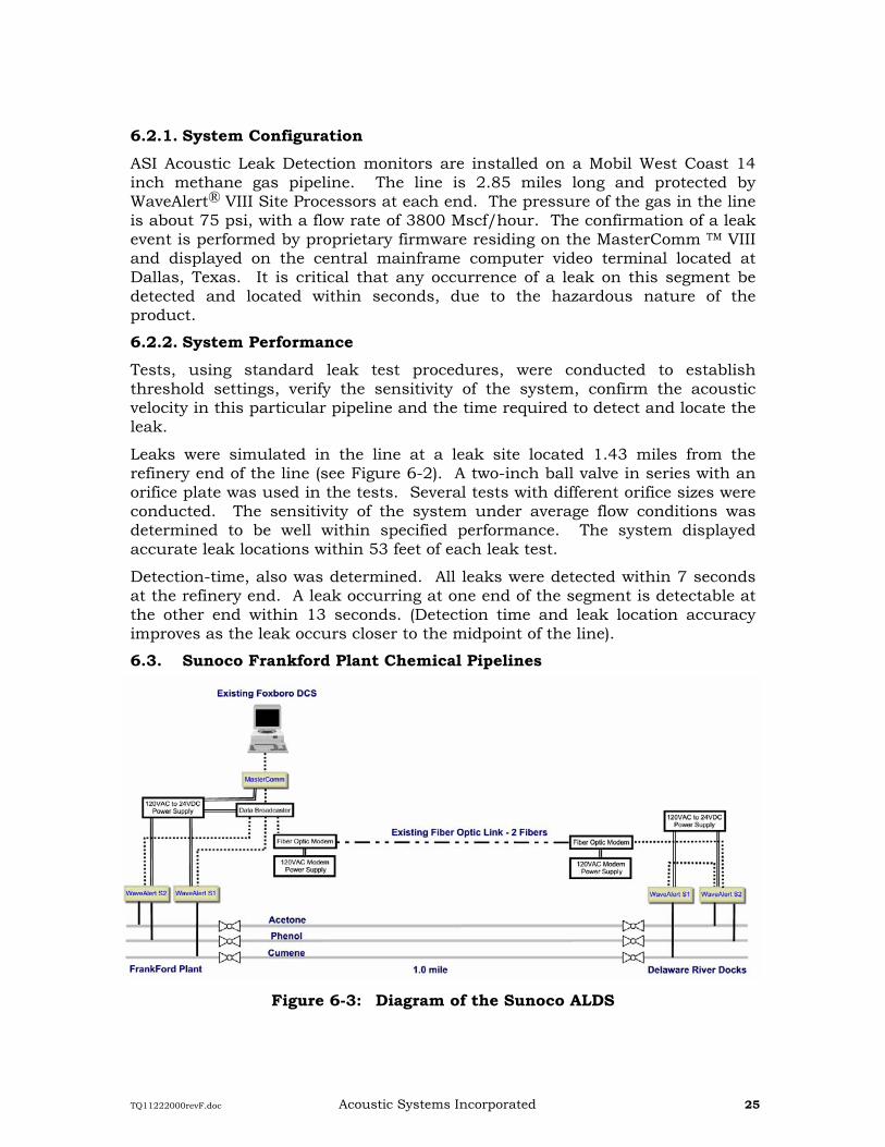
6.3. Sunoco Frankford Plant Chemical Pipelines
Figure 6-3: Diagram of the Sunoco ALDS
TQ11222000revF.doc Acoustic Systems Incorporated 26
In 1999 Sunoco selected the WaveAlert® ALDS to meet local requirements for leak detection on three chemical pipelines. The WaveAlert® VIII system was installed on each of the phenol, acetone and cumene pipelines (Figure 6-3). These pipelines ran from the plant to loading docks on the Delaware River.
6.3.1. System Configuration The system is configured to monitor all three pipelines while ships are being loaded at the dock and also while the pipelines are shut-in. Since the pipelines load ships infrequently (as little as once per week) Sunoco was required to have a leak detection system, which would operate at high sensitivity during zero flow conditions. Since the WaveAlert® ALDS is not based on flow measurement it will maintain high sensitivity without flow in the pipeline.
7. ANALYSIS FORM _____________________________________________________________________________
TQ11222000revF.doc Acoustic Systems Incorporated 27
Gas Data Specific Gravity of the Gas Ratio of Specific Heats of the Gas
Average Compressibility Viscosity (poise) Flow (MMSCF/D)
Liquid Data Bulk Modulus of the Liquid (psi) Density of the Liquid (lb/cu. ft.)
Viscosity (poise) Flow (barrels per day)
Other Data Does SCADA system already exist? If yes, describe what type.
Does a communication system already exist? If yes, describe what type: Radio Microwave Hardwire Dedicated Phone Line
Draw a diagram of pipeline to be studied. Provide: location of branches, location of block valves, instrumentation hardware, control room, populated area and environmentally sensitive areas
Desired Sensitivity Hole size (inches or mm) Accuracy of Location (feet or meters) Speed of detection (seconds)
TABLE OF CONTENTS 1. INTRODUCTION ............................................................................................................. 1
1.1. ACOUSTIC SYSTEMS INCORPORATED........................................................................... 2 1.2. FACILITIES ....................................................................................................................... 3
2. REAL TIME LEAK DETECTION.............................................................................. 4 2.1. PIPELINE MONITORING................................................................................................... 4 2.2. LEAK STATISTICS ............................................................................................................ 4
3. ACOUSTIC LEAK DETECTION................................................................................ 5 3.1. SYSTEM CONFIGURATION .............................................................................................. 5
3.1.1. WaveAlert® VIII Site Processor and Acoustic Sensor Assembly .............................. 6 3.1.2. MasterComm VIII Node Processor............................................................................ 6 3.1.3. Communication Link.................................................................................................. 7 3.1.4. ASI Leak Computer and SCADA Software ................................................................ 8 3.1.5. WaveAlert® VIII and MasterCommTM VIII Hardware .............................................. 8 3.1.6. ASI Leak Computer.................................................................................................. 10
3.3. AVAILABLE CONFIGURATIONS ................................................................................. 16 4. SOFTWARE .................................................................................................................... 17
4.1. WAVEALERT® VIII SITE PROCESSOR FIRMWARE.................................................... 17 4.2. MASTERCOMMTM VIII NODE PROCESSOR FIRMWARE .......................................... 17 4.3. SCADA .......................................................................................................................... 17
5. SYSTEMS ........................................................................................................................ 20
6. TYPICAL INSTALLATIONS AND APPLICATIONS ............................................ 23 6.1. ESSO AUSTRALIA LPG PIPELINE ........................................................................... 23
6.1.1. System Configuration .............................................................................................. 24 6.1.2. System Operation..................................................................................................... 24
6.2. MOBIL WEST COAST METHANE GAS PIPELINE ........................................................ 24 6.2.1. System Configuration .............................................................................................. 25 6.2.2. System Performance ................................................................................................ 25
6.3. SUNOCO FRANKFORD PLANT CHEMICAL PIPELINES ................................................ 25 6.3.1. System Configuration .............................................................................................. 26
7. ANALYSIS FORM ......................................................................................................... 26
____________________________________________________________ This document contains proprietary information concerning Acoustic Systems Incorporated property and it will be held in secrecy and confidence. The explicit use of this document is for the purpose of evaluation or such other purpose as may be agreed upon in writing. This document may not be disclosed to any person other than those within your company or organization. Records or copies may not be made of any drawing, description, specification or any other document, disclosure, or embodiment of the information.
WaveAlert® VIII and MasterComm VIII Specifications WaveAlert VIII and MasterComm VIII processors provide a robust hardware platform, which can be mounted in a standard weather tight electronics enclosure. Climate control is not required, based on the following specification:
Operating Temperature -30 to 85 degrees Celsius (-22 to 185 degrees Fahrenheit)
Storage Temperature -50 to 85 degrees Celsius (-58 to 185 degrees Fahrenheit)
Relative Humidity 0 to 95 percent, Noncondensing
Input Voltage 20 to 36 VDC
Input Current (Nominal) 250 mA @ 24 VDC
WaveAlert® VIII and MasterComm VIII CPU and Memory WaveAlert VIII Site Processor and MasterComm VIII Node Processor employ a high-speed signal processor for all pipeline leak evaluation, computation and processing. Leak detection programs are ran from high speed flash memory allowing for easy program updates. Sensor, GPS and communications status are provided by front panel LEDs.
WaveAlert® VIII and MasterComm VIII Acoustic Leak Detection I/O WaveAlert VIII Site Processor and MasterComm VIII Node Processor each include 4 RS232 serial communications ports. For the MasterComm VIII Node Processor two of these communications ports can be used for sending Acoustic Leak Data to two SCADA systems simultaneously. Both units also include GPS synchronization. The WaveAlert VIII Site Processor can be configured with up to 8 isolated Acoustic Sensor Inputs.
WaveAlert® VIII and MasterComm VIII Configurable RTU I/O Features WaveAlert VIII and MasterComm VIII each include 4 dry contact form 'C' relay outputs. Each unit also includes 4 optically isolated digital inputs. These I/O can be configured for any use including valve control, valve status, alarm control, etc. The WaveAlert VIII Site Processor also can include isolated 4-20 ma inputs from any of the 8 unused Acoustic Sensor Inputs. These inputs can be used for any process measurements including temperature, flow rate, pressure, etc and are powered by the internal WaveAlert sensor power supply. A 16 bit A/D is used for conversion of the inputs.