STEEL CONSTRUCTION TODAY & TOMORROW http://www.jisf.or.jp/en/activity/sctt/index.html Published Jointly by No. 55 December 2018 The Japan Iron and Steel Federation Japanese Society of Steel Construction JISF Operations Back cover Potential of Exterior Diaphragm-type Column to Beam Connections 9 Steel Tubes for Building and CFT Structures 13 Protruding Box Structures Form Expressive Façade and Improve Seismic Resistance 15 HIRAKATA T-SITE 5 Current State of Studies and Research on CFT Structures Current State of Studies of Steel-Concrete Composite Structures 1 Steel-Concrete Composite Structures Feature Articles Serial Article: Latest Design of Steel Buildings in Japan (3) Photo: Atsushi Nakamichi
Potential of Exterior Diaphragm-type Column to Beam Connections
9
Steel Tubes for Building and CFT Structures13
Protruding Box Structures Form Expressive Façade and Improve Seismic Resistance
15
HIRAKATA T-SITE
5 Current State of Studies and Research on CFT Structures
Current State of Studies of Steel-Concrete Composite Structures1
Steel-Concrete Composite Structures
Feature Articles
Serial Article: Latest Design of Steel Buildings in Japan (3)
Photo: Atsushi Nakamichi
In the following article, the recent trend in studies of steel-concrete com-posite structures is briefly introduced. In addition, a study is also introduced of a new steel-concrete structure, for which we are promoting the develop-ment of studies.
Current State of Studies of Steel-Concrete Composite StructuresThe typical steel-concrete composite structures in common use in Japan are of three structures: steel and reinforced concrete (SRC) structures, concrete-filled steel tube (CFT) structures and reinforced concrete column-steel beam (RC+S) mixed structures (Fig. 1). CFT structures are structures that can eas-ily utilize the structural features of-fered by the composite structure, and CFT structures produced by the use of high-strength steel members have been widely applied in the construction of high-rise buildings. RC+S structures are mixed structures composed of re-inforced-concrete columns that offer both high rigidity and economic ad-vantages and steel beams with which the structural span can be made longer, and thus they are extensively applied in the construction of long-span office buildings, commercial facilities and lo-gistics warehouses.
In order to survey the recent trend of studies of steel-concrete compos-ite structures in Japan, an analysis was made of 102 study reports in the field of steel-concrete composite structures published in the Summaries of Techni-cal Papers of the Annual Meeting for FY2018 of the Architectural Institute of Japan (AIJ)2). Fig. 2 shows a break-down of study reports in the field of steel-concrete composite structures. As shown in the figure, the mainstream in
recent studies of steel-concrete com-posite structures has been on CFT and RC+S structures.
While the content of studies of CFT structure is wide-ranging, the main tar-gets in studies have been placed on the application of super high-strength steel, rectangular-shaped CFT col-umns, long-period seismic motion, slender columns and built-in steel re-inforcement.
In the study of RC+S mixed struc-tures, extensive studies have been made of the effect of grade differences (height direction) in right and left steel beams attached to RC columns and the differences in eccentricities (horizon-tal direction) of the beam core to the column core that affect the behaviors of connections. Further, studies have been reported on the mixed structures that consist of RC sections in the beam ends and H-shaped steel frame in the middle of the span. In addition, a lot of studies of the attachment of braces have also been reported.
Very few studies have recently been made in the field of SRC structures, and instead of this, the study of steel-concrete (SC) composite structures is
increasingly being promoted. In the field of the study of SC struc-
tures, most studies target structur-al members in which steel reinforc-ing bars are eliminated from the SRC structure, and studies are actively be-ing promoted on structural members, column-beam connections and seis-mic-resistant walls composed of con-crete encased steel (CES) structures
Fig. 1 Typical Steel-Concrete Composite Structures in Use in Japan1)
Steel beam
RC column Cover plate
Steel tube
Encased steel
(a) SRC (b) CFT (c) RC column-Steel beam
1 Steel Construction Today & Tomorrow December 2018
Current State of Studies of Steel-Concrete Composite Structuresby Junichi SakaiProfessor, Fukuoka University
Junichi Sakai: After receiving the master’s degree at the Graduate School of Engineering, Kyushu Uni-versity in 1989, he became associate professor at the Kyushu University in 2001. He assumed his current position as professor, Department of Architecture, School of Engineering, Fukuoka University in 2007. His specialized field covers structural engineering and steel-concrete composite structures.
CFT28
RC+S27
SC CompositeMember
18SC Composite
Member18
M.S.C6
FRP5
Others18
CFT: Concrete-filled steel tubeRC+S: Mixed frame of RC column and steel beamM.S.C.: Mechanical shear connectorFRP: Fiber-reinforced plastics
Total: 102 study reports (Summaries of Technical Papers of AIJ Annual Meeting for FY2018)
Fig. 2 Breakdown of 102 Study Reports on Steel-Concrete Composite Structures2)
that employ carbon fiber-mixed fiber concrete. In addition, studies are also being promoted on various kinds of SC beams including SC foundation beams and octagonal-section SC columns. Re-garding octagonal-section SC columns, an explanation will be made later.
In terms of the number of contri-butions at the AIJ Annual Meeting for FY2008, while the total number has decreased, it is noted that studies of mechanical shear connectors and fi-ber-reinforced plastics have tended to increase. In building construction in Japan, the headed stud has been wide-ly applied as the device to transfer the stress between steel and concrete, which however brings about concerns about the increase in the number of headed studs to be applied. To cope with such a situation, studies of the perfobond connectors used in the field of civil engineering have recently been promoted for the field of building con-struction.
Fig. 3 shows an example of the re-sults of a pressing test conducted by embedding three kinds of mechanical shear connectors into concrete-head-ed studs, perfobond connectors and new burring connectors3). Even for the test specimen prepared by setting the maximum strength of both the head-ed stud and perfobond connector to an identical level, it can be understood from the test results that the stiffness of the headed stud was low but that of the perfobond connector was high. Further, as can be seen in the figure, both the stiffness and strength of the new burring shear connector employ-ing the burring steel plate are high, and as a result it is expected that the new connector will be put into practical use.
In the field of civil engineering,
structures employing fiber-reinforced plastics (FRP) have been constructed, but there are concerns about increasing construction costs attributable to its ap-plication. In the field of building con-struction, its application has been lim-ited only to parts of building structures. However, FRP offers high structural performance such as being lightweight and has high strength and stiffness, and thus its application is considered to grow in the future. Recently, studies and exposure tests have been made for the compression strength of carbon-fi-ber reinforced plastics (CFRP) mem-bers and the application of CFRP in the splice plates of high-strength bolt fric-tion joints.
Among the “others” pertinent study reports shown in Fig. 2 are studies on buckling-restraint braces, composite slabs, and composition with wooden materials and steel pipe pile head joints.
Development Study of Octago-nal-section SC ColumnSteel and reinforced concrete (SRC) structures are structures that were orig-inally developed in Japan and offer high seismic resistance. However, they require reinforcing bar arrangement and concrete placement in addition to steel-frame fabrication, and as a result, the construction process becomes com-plex and construction costs tend to rise. Accordingly, while SRC structures are applied to parts of building structures, construction of all SRC-layer building has decreased.
Aiming at further improving seis-mic resistance and enhancing manpow-er and labor savings involved in SRC construction, we are promoting the development studies into octagonal-section steel-concrete (SC) columns
shown in Fig. 4. A dynamic feature of octagonal-section SC columns lies in that, because concrete surrounded by cruciform steel frame can effective-ly been confined by the use of steel-frame flanges and webs, the bending resistance and deformation capacity can be enhanced. Specifically, the web of cruciform steel frames is located in the center of the column section, and thus the octagonal section column can resist high compressive axial load and suppress axial contractions. As a re-sult, octagonal-section SC columns show stabilized large deformation be-havior. Further, both bending strength and stiffness can easily be adjusted by adjusting the thickness and width of steel-frame flanges.
Fig. 5 shows the conditions of con-crete-confined effects obtained by the test in which a uniform compressive load is applied to the octagonal-section concrete. As can be seen in the figure, the compressive strength and deforma-tion capacity of octagonal-section col-umn concrete are improved compared to those of plain concrete (no reinforce-ment). Because of the limited space for this study report, the method of anal-ysis cannot be mentioned, but it can be understood from the figure that the compressive behavior of concrete can be traced by means of analysis that takes the concrete-confined effect into account4).
Fig. 6 shows the results of a test in which the constant axial load and cy-clic lateral load were applied to octag-onal SC columns. It can be seen in the figure that even when the steel-frame dimensions differ one by one, the oc-tagonal column possesses high seismic resistance. The mechanism line in the figure indicates the shear strength of
Fig. 4 Cross Section of Octagonal- section SC Column
P12-0Perfobond connector
S13Stud
0
50
100
150
200
250
0 5 10 15 20
Load
per
con
nect
or Q
(kN
)
Slip δ (mm)
B6-6Burring connector (new)
Fig. 3 Relationship between Load and Slip of Mechanical Shear Connector3)
2December 2018 Steel Construction Today & Tomorrow
SC columns in the case when the full plastic moment of the column section, calculated using the yield strength of steel and the compressive strength of concrete, is to be demonstrated on the column head and base. The figure al-so shows the result of an analysis that takes into account the concrete-con-
fined effect, and it can be said that the test results are precisely evaluated by this analysis.
Fig. 7 shows the column-beam con-nection of a mixed-framing structure composed of octagonal-section SC col-umns and steel-frame beams. As shown in the figure, the detail of weld-join-
ing of an exterior diaphragm and verti-cal stiffener is proposed to confirm the transfer of stress occurring in column-beam connections5). Further, two cruci-form frame test specimens composed of octagonal-section SC columns and steel-frame beams were prepared, and a test was conducted in which a con-stant axial load was applied for mixed structures to handle the stress occurring during an earthquake, and then an an-ti-symmetrical positive/negative alter-nating cyclic shear load was applied to both ends of the beam. Fig. 8 shows the test results obtained so far.
In the test, the design was made so that attainment to the ultimate strength by column-beam connection precedes that by column and beam in each of these two specimens. One difference between these two specimens is whether or not the vertical stiffener is arranged on the column-beam connection. While both specimens show excellent hyster-esis loop in seismic resistance, the di-agonal-direction concrete compression
Fig. 6 Relationship between Shear Strength and Rotation Angle of Octagonal-section SC Column Member4)
0
200
400
600
800
1000
0 2 4 6 8 10
cN (kN)
δ (mm)
CH-200x80x4.5x4.5
Test
Analysis(Confined effect)
Plainconcrete
Fig. 5 Concrete-confined Effect of Octagonal-section SC Column Member4)
3 Steel Construction Today & Tomorrow December 2018
strut is likely to form in the connection panel due to the arrangement of the ver-tical stiffener, and as a result the shear strength of the connection slightly in-creases. Further, it has become possible to confirm the effect of vertical stiffen-er arrangement on the suppression of shear deformation in connections6).
In the installation of octagonal-sec-tion SC columns, reinforcing bar ar-rangement is not required in terms of construction, and steel-frame flanges can be used as the concrete form, which is considered to lead to simplified con-struction work. For octagonal-section SC columns, plain concrete is planned to be applied, and the high-level quality control required for the concrete used for CFT structures is not required. To that end, we are examining the appli-
cation of octagonal-section SC columns in the construction of low- and medi-um-rise buildings.
High Expectations for Octago-nal-section SC ColumnsThe trend in studies of steel-concrete composite structures in Japan has been analyzed based on the reference lit-erature2), the results of which are in-troduced above. The development of studies is proceeding for new octago-nal-section SC columns and octagonal column-steel frame mixed structures that are expected to not only allow for both manpower and labor savings but also offer enhanced structural perfor-mance. Their structural behavior is al-so introduced above. ■
References1) AIJ: Teaching materials for struc-
ture, 2014.32) AIJ: Summaries of Technical Papers
of Annual Meeting, Vol. Structure III, pp. 1345-1548,2018.08. (in Japanese)
3) Teruhisa Tanaka and Junichi Sakai: Development of a new shear con-nector using burring steel plate, Re-search, Development, and Practice in Structural Engineering and Con-struction, ASEA-SEC-1, Perth, No-vember 28–December 2, 2012.
4) Yo Kuratomi, Junichi Sakai, Teruhi-sa Tanaka and Kensuke Kawahara: An analytical study on elastic-plas-tic behavior of steel and concrete composite columns with cruciform steel sections,Proceedings of the Ja-pan Concrete Institute, pp.1039-1044, 2014.7. (in Japanese)
5) Yo Kuratomi, Junichi Sakai, Ter-uhisa Tanaka and Daiki Fuchiga-mi: Structural performance of steel beam to steel and concrete com-posite column joints with band plates,Proceedings of the Japan Concrete Institute, pp. 1057-1062, 2017.7. (in Japanese)
6) Yo Kuratomi, Junichi Sakai, Ter-uhisa Tanaka and Daiki Fuchigami: An experimental study on elastic-plastic behavior of mixed structures composed of SC columns and steel beams, Proceedings of the Japan Concrete Institute, pp. 1117-1122, 2018.7. (in Japanese)
External diaphragm
Vertical stiffener
SC column
Steel beam
Vertical stiffener
Fig. 7 Column-Beam Connection of Mixed Structure Composed of Octagonal-section SC Column and Steel-frame Beam
-100
-75
-50
-25
0
25
50
75
100
-6 -4 -2 0 2 4 6
bPu
-bPu
jPu
jPu'
-jPu
-jPu'
-100
-75
-50
-25
0
25
50
75
100
-6 -4 -2 0 2 4 6
bPu
jPu
jPu'
-jPu
-jPu'
(a) With vertical stiffener (b) No vertival stiffener
Beam end load P (kN)P (kN)
Beam end load
Rotaition angle R (%) Rotaition angle R (%)- Pub
Fig. 8 Relationship between Load and Deformation of Column-Beam Connection Composed of Octagonal-section SC Column and Steel-frame Beam6)
4December 2018 Steel Construction Today & Tomorrow
Concrete-filled steel tube (CFT) struc-tures are a kind of steel-concrete com-posite structure. They feature high structural performance such as high load-carrying capacity and high defor-mation capacity. In Japan, their appli-cation started in the latter part of the 1950s, and CTT structures have widely been used in the construction of a num-ber of high-rise office buildings.
The first study report of CFT struc-tures submitted in Japan was the “Ex-periment and analytical study on buckling loads of CFT compressive members” prepared by Prof. Shizuo Ban and others in 1956. Then in 1961, a similar report was submitted: “Experi-ment and analytical study on the centri-cally loaded CFT slender columns” by Prof. Takeo Naka, Prof. Ben Kato and others. In 1981, Prof. Kenji Sakino re-ported a doctoral dissertation on CFT structures, a first of its kind in Japan.
In the “Project to Develop New Ur-ban-type Multiple Dwelling Housing System” promoted for five years starting from 1985 by the Ministry of Construc-tion, the CFT structure was adopted as a structural system for high-rise apart-
ment housing. In this regard, an experi-mental study on beam-column members was conducted to evaluate the perfor-mance of the structural system thus adopted. Further, in “Composite and Hybrid Structures,” a U.S.-Japan Co-operative Earthquake Engineering Re-search promoted over five years starting from 1993, the CFT working group was established, and experimental research on the column members and beam-to-column connections of CFT structures was promoted by widely changing the strength of materials and the width-thickness ratio and diameter-thickness ratio of steel tubes.
The recent trends in research and studies on CFT structures are intro-duced in the following:
Design Guidelines and Applica-tion RangesTwo latest versions of the design guide-lines for CFT structures have been pub-lished in Japan-Recommendations for Design and Construction of Concrete Filled Steel Tubular Structures (2008) by the Architectural Institute of Ja-pan (AIJ) and Technical Standards and
Commentaries for Concrete Filled Steel Tubular Structures (2012) by the Asso-ciation of New Urban Housing Technol-ogy. In addition, the Guidebook on De-sign of Concrete Filled Steel Tubular Structures for use for young designers and university students has also been published by the Architectural Institute of Japan.
The application range of material strengths for CFT structures specified in the AIJ’s Recommendations for De-sign and Construction is set at 18~90 N/mm2 for the compressive strength of concrete, 590 N/mm2 or lower for the tensile strength of steel, and 235~440 N/mm2 for the yield stress of steel tubes (Table 1). The standard section of CFT columns is set to be square and circu-lar (Fig. 1). In addition, experimental studies are being promoted on the ap-plication of rectangular CFT columns and the strength and deformation capac-ity of reinforced-type CFT columns in which steel reinforcing bars are built-in into the steel tube.
5 Steel Construction Today & Tomorrow December 2018
Fig. 1 Cross Sections of CFT Columns
Square Circular Rectangular
Table 1 Requirements for CFT Structures
Compressive strength of concrete*
Tensile strength of steel*
Yield stress of steel*
Ratio of limiting value of width (diameter) to thickness
Current State of Studies and Research on CFT Structuresby Keigo Tsuda, Emeritus Professor, and Masae Kido, Associate ProfessorThe University of Kitakyushu
Masae Kido: After finishing the doctoral program at the Graduate School of the University of Kitaky-ushu, she became lecturer of the University of Kitakyushu in 2007. She assumed her current position as associate professor of the Uni-versity of Kitakyushu in 2012.
Keigo Tsuda: After finishing the master course at the Graduate School of Ky-ushu University, he served as research assistant of Kyushu University in 1977 and then as associate professor of Ky-ushu University. He became professor of the University of Kitakyushu in 2001 and emeritus professor in 2018.
Recent Trends in Studies on CFT Column Members• Ultimate Strength of Columns
Subjected to Axial LoadsIn the currently-prevailing AIJ’s Recom-mendations for Design and Construction of Concrete Filled Steel Tubular Struc-tures, as shown in Fig. 2, the slenderness parameter of columns subjected to com-pressive force is examined by selecting the ratio lk/D of the effective length lk to the section depth D, and where the ratio is lk/D=4 or lower, columns within this ratio are defined as short columns, where the ratio is lk/D=more than 4~12 or low-er as intermediate columns, and where the ratio is lk/D=more than 12 as slen-der columns, and the design equation is changed depending on the ratio lk/D se-lected.
As of now, as the compressive strength evaluation equation for CFT columns, the design equation is proposed that takes the normalized slenderness ra-tio of steel columns as the slenderness in-
dicator and is based on strength cumula-tively added with the buckling strength of both steel and concrete columns with no distinction as short, intermediate and slender columns.
Fig. 3 shows a comparison between the column strength thus proposed and the compressive strength calculated us-ing the AIJ’s Recommendations. In the figure, sσy is the yield stress of the steel tube and cσB the compressive strength of concrete. As shown in Fig. 3, the pro-posed strength cumulatively added with the buckling strength of both steel and concrete columns well agrees with the buckling strength calculated using AIJ’s Recommendations in all ranges of nor-malized slenderness ratios even when the distinction as short, intermediate or slen-der columns is not applied1).
• Ultimate Strength of Columns Subjected to Axial Load and Flexural Shear Stress
For columns subjected to both compres-sive strength and flexural shear stress, the current AIJ’s Recommendations shows design equations for each of three differ-ent types of columns-short, intermedi-ate and slender, as in the case of the de-sign of compressive members. Presently, as with compressive members, the range in which the full plastic moment of col-umn sections can be expected to display in terms of the relation with the normal-ized slenderness ratio of steel tube col-umn λc, the axial load ratio of column ny and the member end bending moment ra-tio κ is being examined using Fig. 4 as an analytical model.
That is, in the relational equation of
ny・λc2=α(1+κ), when the value of α is
0.05 or lower, it can be understood from the correlation between the bending mo-ment and the axial load vis-à-vis the maximum strength of columns shown in Fig. 5 that the full plastic moment of the CFT column section can be expected to come into play. Currently, the method to evaluate the column strength in the range in which the full plastic moment of the column section cannot be expected is be-ing examined.
As regards the square CFT columns causing shear fracture, there are cas-es in which fractures occur in the case of a shear span ratio=1 or lower, but it has been known that the square CFT col-umn’s hysteresis characteristic for shear fracture is not inferior to the performance in the case of bending fracture. Current-ly, study is underway on the shear frac-ture of circular CFT columns.
• Studies on Long-period Seismic Motions
There are concerns about the effect of a great earthquake occurring with the Nan-kai Trough as an epicentral region on high-rise buildings with a long natural period. Studies on CFT columns to treat long-period seismic motions are current-ly being promoted. In the Building Stan-dard Maintenance Promotion Project of the Ministry of Land, Infrastructure, Transport and Tourism, examinations were made of the method to verify the safety of CFT columns against long-pe-riod seismic motions in 20132), in which tests were made pertaining to the case where CFT columns are subjected to constant displacement amplitude cyclic
Buc
klin
g st
reng
th
Normalized slenderness ratio of steel column
0
2000
4000
6000
8000
0 0.5 1 1.5 2
10000 c B
120
90
6036
lk/D=30lk/D=50
c
12000
Fig. 3 Column Strength Curves
Ncr (kN)
=250 mm =12 mm =20.8 =325 N/mm2
DtD/ts y
=150 N/mm2
Proposed column strength
AIJ CFT Recommendations
6December 2018 Steel Construction Today & Tomorrow
Nu
lk/D
Short
Slender column
Intermediate
1240
Buc
klin
g st
reng
th
Buckling length - section depth ratio
Fig. 2 Range of Short, Intermediate and Slender Columns
M2= M1
M1N
N
Mm
M1
M2
(M1max)
(Mmax)
= M1
Dt
Column section
Fig. 4 Loading Conditions and Moment Diagrams
0
0.2
0.4
0.6
0.8
1
1.2
0 0.2 0.4 0.6 0.8 1 1.2 1.4M1max/Mp
FP
0.1
0.25
0.150.2
0.3
=0s y=325 N/mm2
c B=90 N/mm2
ny
=0.05
Flexural strength
Axi
al lo
ad
Fig. 5 Column Strength Curves
loading under constant or variable axial loads. In addition, based on the capaci-ty obtained from member tests, a proce-dure has been proposed that evaluates CFT column damage employing seismic response analysis.
Meanwhile, there is high demand to accumulate test data. To meet such a de-mand, in 2015 the Building Commit-tee of the Japan Iron and Steel Federa-tion entrusted to the Japanese Society of Steel Construction the study on long-term seismic motion, in which the Work-ing Group on Survey and Study on Re-tained Performance of Column Members against Long-period Seismic Motions was established to promote a three-year study from 2015 to 2017.
As a link with the three-year study, we conducted a number of tests on CFT col-umns subjected to constant displacement
amplitude cyclic loading under constant axial loads by setting as the experimen-tal variable the ratio of effective length to section depth lk/D, the axial load ratio ny, the displacement amplitude (rotation an-gle) R0, and the sectional shape (square, circular)3). Examples of test results thus far obtained are introduced below:
Tests were carried out under the load-
ing condition shown in Fig. 6. Photo 1 shows the CFT column loading appa-ratus. Fig. 7 shows the relationship be-tween the lateral load and the rotation angle in the following three cases at lk/D=14: axial load ratio =0.15 and rotation angle=1.5%; axial load ratio =0.3 and ro-tation angle=1.5%; and axial load ratio =0.6 and rotation angle=1%. The figure
7 Steel Construction Today & Tomorrow December 2018
Fig. 7 Relationship between Lateral Load and Rotation Angle
Specimen
Photo 1 CFT column loading apparatus
Axial forceAxial force
Lateral forceLateral force
also shows the case of tests made for hol-low steel tube columns. Fig. 8 shows the trend of lateral loads (Q0i/Qmax) at the ro-tation turning point and the trend of ax-ial strain (εv%). Photo 2 shows the col-umn base after testing. As the axial load ratio and the displacement amplitude be-come large, the reduction of the load be-comes large. The future plan calls for the proposition of a method to evaluate the strength deterioration performance of CFT columns.
• Studies on Impact ResistanceIn the Great East Japan Earthquake that occurred in 2011, building damage caused by tsunamis posed a lot of con-cern. Because CFT columns can be ex-
pected to demonstrate high impact re-sistance, a method to quantitatively evaluate impact resistance has been de-veloped4).
• CFT Columns Employing Super High-strength Steel
Tests for CFT column members pro-duced employing super high-strength steel products with tensile strength rat-ings of 800~1,000 N/mm2 are underway. In the manufacture of weld built-up box column members, because strict welding conditions are imposed on over-match-ing welding, studies of CFT members built up by means of under-matching welding are currently being promoted.
Development of CFT Struc-tures with Higher Structur-al PerformanceIt is expected that a structural performance evaluation method with high precision will be es-tablished for CFT columns that not only are produced employ-ing high-strength steel members beyond the application range of currently-prevailing design stan-dards but also include slender columns having diverse section-al configurations. We expect fur-ther development of CFT struc-
tures that will offer higher structural performance. ■
References1) Masae Kido, Keigo Tsuda, Masayuki
Haraguchi: Evaluation of strength of concrete filled steel tubular columns with flexural buckling, J. Struct. Con-str. Eng., AIJ. Vol. 82 No. 735, pp.753-763, 2017.5 (in Japanese)
2) Narihara Hiroyuki et. al: Study on safe-ty assessment methods for super-high-rise steel buildings against long-period earthquake ground motions, Part 27-33, Summaries of Technical Paper of Annual Meeting, Architectural Institute of Japan C-III, pp.1251-1264,2014.9 (in Japanese)
3) Masae Kido, Toshiyuki Fukumoto, Kei-go Tsuda, Yasuo Ichinohe, Koji Morita: Study on the Strength and cyclic rotation capacity of CFT beam-columns against long duration earthquake, Steel Con-struction Engineering, Vol. 24 No.94, pp.49-64, 2017.6 (in Japanese)
4) Akihiko Kawano, Hiromitsu Kawaguchi: Development of an evaluation method for impact resistant capacity of concrete filled tubular members against tsuna-mi flotsam collision, J. Struct. Constr. Eng., AIJ. Vol. 80 No. 715, pp,1497-1503, 2015.9 (in Japanese)
8December 2018 Steel Construction Today & Tomorrow
0
0.5
1
1.5
2
2.5
3
0.4
0.5
0.6
0.7
0.8
0.9
1
0 50 100 150
Late
ral l
oad
Q0i
/Qm
ax
lk/D=14 positive side
Cycles
0.2
Axi
al s
trai
nv(%
) n=0.15, R=1.5%CFT
Steeln=0.3, R=1.5%n=0.6, R=1%
CFTSteel
n=0.15, R0=1.5%n=0.3, R0=1.5%n=0.6, R0=1%
Fig. 8 Relationship between the Axial Strain, Lateral Load and the Number of Cycles
ny=0.15, R0=1.5% ny=0.3, R0=1.5% ny=0.6, R0=1%
ny=0.15, R0=1.5% ny=0.3, R0=1.5% ny=0.6, R0=1%
CFT
Steel
Photo 2 Column bases after testing
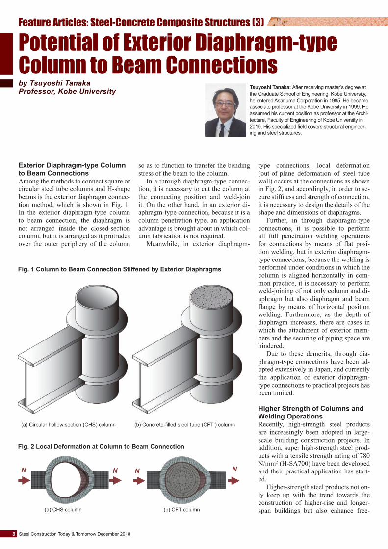
Exterior Diaphragm-type Column to Beam ConnectionsAmong the methods to connect square or circular steel tube columns and H-shape beams is the exterior diaphragm connec-tion method, which is shown in Fig. 1. In the exterior diaphragm-type column to beam connection, the diaphragm is not arranged inside the closed-section column, but it is arranged as it protrudes over the outer periphery of the column
type connections, local deformation (out-of-plane deformation of steel tube wall) occurs at the connections as shown in Fig. 2, and accordingly, in order to se-cure stiffness and strength of connection, it is necessary to design the details of the shape and dimensions of diaphragms.
Further, in through diaphragm-type connections, it is possible to perform all full penetration welding operations for connections by means of flat posi-tion welding, but in exterior diaphragm-type connections, because the welding is performed under conditions in which the column is aligned horizontally in com-mon practice, it is necessary to perform weld-joining of not only column and di-aphragm but also diaphragm and beam flange by means of horizontal position welding. Furthermore, as the depth of diaphragm increases, there are cases in which the attachment of exterior mem-bers and the securing of piping space are hindered.
Due to these demerits, through dia-phragm-type connections have been ad-opted extensively in Japan, and currently the application of exterior diaphragm-type connections to practical projects has been limited.
Higher Strength of Columns and Welding OperationsRecently, high-strength steel products are increasingly been adopted in large-scale building construction projects. In addition, super high-strength steel prod-ucts with a tensile strength rating of 780 N/mm2 (H-SA700) have been developed and their practical application has start-ed.
Higher-strength steel products not on-ly keep up with the trend towards the construction of higher-rise and longer-span buildings but also enhance free-
so as to function to transfer the bending stress of the beam to the column.
In a through diaphragm-type connec-tion, it is necessary to cut the column at the connecting position and weld-join it. On the other hand, in an exterior di-aphragm-type connection, because it is a column penetration type, an application advantage is brought about in which col-umn fabrication is not required.
Meanwhile, in exterior diaphragm-
(a) CHS column (b) CFT column
Fig. 2 Local Deformation at Column to Beam Connection
Potential of Exterior Diaphragm-type Column to Beam Connectionsby Tsuyoshi TanakaProfessor, Kobe University Tsuyoshi Tanaka: After receiving master’s degree at
the Graduate School of Engineering, Kobe University, he entered Asanuma Corporation in 1985. He became associate professor at the Kobe University in 1999. He assumed his current position as professor at the Archi-tecture, Faculty of Engineering of Kobe University in 2010. His specialized field covers structural engineer-ing and steel structures.
dom in design. It is expected that high-er-strength steel products will contribute towards the creation of affluent archi-tectural spaces and structure that suffers less damage during major earthquakes.
In particular, application of 780 N/mm2-grade steel products for steel col-umns in building construction brings about considerable merits. However, when examining the wider application of 780 N/mm2-grade steel products, weld performance and welding operation are obstacles to its wider application. Guar-anteeing the preparation of over-match-ing weld joints for 780 N/mm2-grade steel products poses problems such as extreme difficulty in construction and leads directly to high construction costs.
When steel products with a tensile strength of 780 N/mm2 are used for col-umns and those of 590 N/mm2 or lower are used for beams and diaphragms, and further, when the connection is prepared by the use of exterior diaphragms, it be-comes unnecessary to weld columns in the preparation of column to beam con-nections.
Currently in Japan, triggered by a shortage of welders, development of var-ious kinds of robotic welding methods is actively being promoted for use for weld-joining of columns and diaphragms, and as a result, the horizontal position weld-ing of columns and diaphragms by ro-botics welding is becoming available. To that end, there is a fair possibility of ef-fectively handling tasks involved in the trend for higher strength of columns by the optimum use of exterior diaphragm-type connections.
CFT Columns and Local Deforma-tionAs explained above, because local de-formation occurs in exterior diaphragm-type connections, there are cases in which column to beam connections pre-pared by the use of exterior diaphragms are not accepted as a rigid connection. While local strength is improved by the use of super high-strength steel, local stiffness is not improved. In exterior di-aphragm-type connections, diaphragms are not arranged inside the steel tube column, and thus concrete can easily be filled inside the column. Accordingly, suppression of local deformation in col-umn to beam connections can be expect-ed by the use of concrete-filled steel tube (CFT) columns.
Structural Tests• Test SpecimensThe test specimens were prepared by joining circular steel tube columns (○-300×12) manufactured by press-form-ing 780 N/mm2-grade steel plates (H-SA700) with 490 N/mm2-grade H-shape beams (H-400×150×9×16, SN490B) by the use of exterior diaphragms, on which the tests were conducted. Exam-ples of the tests conducted are introduced below:
Fig. 3 shows the structure of column to beam connection specimen. The depth of the diaphragm (SN490B) is hd=50 mm, and the plate thickness td =16 mm. Welding of diaphragms and steel tubes adopted in the test is by grooved fil-let welding with a bevel angle of 60°as
shown in the figure, and diaphragm and steel tube were weld-joined by means of CO2 gas shielded arc welding employing welding wire (YGW18) for use for 490 N/mm2-grade steel.
The tests were conducted for two cas-es using two specimens: a circular hol-low section (CHS) steel tube specimen (TD-16/H) and a concrete-filled steel tube (CFT) specimen (TD-16/C). The design standard strength of filling con-crete was set at Fc24, and crushed stone with a maximum size of 20 mm was used for the coarse aggregate.
• Loading and Measurement Methods
As shown in Fig. 4, one end of the cir-cular column is joined to the pin jig, and
Fig. 3 Test Specimen (unit: mm)
16
16
12
400150
300
50
400
16
12
300 S=11
Fig. 4 Specimen and Test Setup
10December 2018 Steel Construction Today & Tomorrow
another end to the pin roller jig, to which positive/negative increment cyclic load-ing is applied using the hydraulic oil jack installed on the beam end.
The displacement transducers are arranged in the vicinity of the connec-tion to measure local deformation Lθ, beam deformation Bθ and total defor-mation Tθ(=Lθ+Bθ) including both the local and beam deformations shown in Fig. 5.
The loading cycle is set at ±Bθp,
±2Bθp, ±4Bθp, ±6Bθp and ±8Bθp for Tθ by setting as the standard the elastic deformation angle Bθp that corresponds to the beam’s full plastic strength BPp, and the cyclic loading mentioned above is twice applied to the specimen respectively.
• Test ResultsFig. 6 shows the relationship between the beam end load P of two specimens and Tθ, Lθ and Bθ. The broken line in
the figure shows the calculated value of the beam’s elastic stiffness and the full plastic strength BPp. The progress of the test for each of two specimens is as shown below:
In the specimen TD-16/H of the cir-cular hollow section (CHS) steel tube column, local yielding preceded, but along with the increase in the load ap-plied, plasticization of beam became clear at the loading cycle of ±4Bθp. At the cycle of ±2Bθp, ductile crack-
(a) CHS column
(b) CFT column
(1) Tθ (2)Lθ (3) Bθ
Fig. 6 Load-Deformation Curves
Fig. 5 Total Beam Deformation Tθ, Local Deformation Lθ and Beam Deformation Bθ
11 Steel Construction Today & Tomorrow December 2018
ing occurred at the internal corner sec-tion, and at the first cycle of ‒ 6 Bθp, as shown in Fig. 7, this cracking devel-oped diagonally to the diaphragm side to cause a reduction in load-carrying performance.
In the specimen TD-16/C of the concrete-filled steel tube (CFT) col-umn, local yielding and beam yielding simultaneously occurred at the loading cycle of ±2 Bθp, but since then the plas-tic deformation of beam steadily ex-
celled. At the cycle of ±4 Bθp, ductile cracking occurred at the internal cor-ner section, and at the first cycle of ‒8 Bθp, after this cracking developed di-agonally to the diaphragm side, dia-phragm caused a fracture. Meanwhile, local buckling of the beam was ob-served at the cycle of ±4Bθp.
When comparing deformation be-tween TD-16/H and TD-16/C, local stiffness of TD-16/C was increased by filling concrete by 1.7 times, and it is
known that plasticization of the beam was promoted.
Fig. 8 shows the positive-side skel-eton curve in the case in which the P-Tθ relationship is made dimensionless using BPp and Bθp. The elastic stiff-ness in the P-Tθ relationship reach-es a level that falls short of the case of beam end rigid connection by 12% due to concrete filling, and as a result it is known that elasto-plastic behavior and plastic deformation capacity nearly similar to those of the beam-collapse type can be obtained for rigid connec-tion framing.
Potential Exterior Diaphragm-type CFT Column to Beam ConnectionsExterior diaphragm-type connections are the traditional connection system. This type of connection can offer ef-fective solutions in the application of steel tube columns manufactured using super high-strength steel products. In cases when the development and diffu-sion of robotics flat-position welding will be promoted in the future, I con-sider it rational to choose exterior di-aphragms for column to beam connec-tions. ■
0
0.2
0.4
0.6
0.8
1
1.2
1.4
1.6
1.8
0 2 4 6 8 10
T / p
P/B Pp
TD-16/C
TD-16/H
: ePp
: Pmax
Fig. 8 Skelton Curves
Fig. 7 Fracture of Diaphragm
12December 2018 Steel Construction Today & Tomorrow
BCR and BCP Standards for Cold-formed Square Steel TubesCold-formed square steel tubes are used mainly as columns in steel-frame build-ing structures in Japan and are one of the most popular steel products for build-ing columns. The manufacturing process takes either of two forms: roll forming (BCR) and press forming (BCP). Fig. 1 shows the manufacturing process.
Neither BCP nor BCR standards are established in the JIS (Japanese Industri-al Standards), but listed in MDCR (stan-dards for steel products for construction) established by the Japan Iron and Steel Federation. The steel products specified in these standards are structural members approved by the Ministry of Land, Infra-structure, Transport and Tourism of Japan.
The available size range is 200×6 mm~550×25 mm for BCR and 200×6
ly, and their mechanical properties such as yield point are the same as those in the JIS SN standard (rolled steels for build-ing structures). Charpy absorption ener-gy is specified at 27J or more at 0ºC for
mm~1,000×40 mm for BCP.Chemical composition is shown in Ta-
ble 1. Mechanical properties are shown in Table 2. BCP235 and BCP325 corre-spond to SN400 and SN490 respective-
Steel Tubes for Building and CFT StructuresCommittee on Overseas Market Promotion, The Japan Iron and Steel Federation
Table 1 Chemcal Composition of BCR and BCP Materials (%)Type
Notes:1) In case when elements to fix N, such as Al, are added and inclusion of solid-solution type N is 0.006% or below, total inclusion of N can be increased up to 0.009%. 2) Ceq = C+Mn/6+Si/24+Ni/40+Cr/5+Mo/4+V/14 3) Pcm = C+Si/30+Mn/20+Cu/20+Ni/60+Cr/20+Mo/15+V/10+5B; Applied in place of Ceq according to the agreement between supplier and purchaser.
Type designation
400 N/mm2
grade
490 N/mm2
grade
MDCR0002-2017
MDCR0003-2017
MDCR0012-2014
Material standard Symbol
BCR295
BCP235
BCP325
BCP325T
t<12 mm
295/
235/
325/
325/
12≤t
295/445
235/355
335/445
335/445
t<12 mm
-
-
-
-
12≤t
90
80
80
80
t≤16 mm
231)
18
17
17
16<t
271)
22
21
21
6/22
6/40
6/40
6/40
Thicknessmm
Min/Max
400/550
400/510
490/610
490/610
Tensile strength Min/Max
272)
272)
272)
702), 3)
Charpy impacttest; Absorbed
energyJ Min (0℃)
Yield point or strength N/mm2) Min/Max
Yield ratio %Max
Elongation % Min
Table 2 Mechanical Properties of BCR and BCP Materials
Notes:1) JIS No.5 test piece (tube axial direction): No.1A test piece for others 2) Applied for wall thicknesses of over 12 mm and average value of 3 test pieces 3) Applied for both plain/corner parts
Slit coilLeveler
Shear Coil-to-coil weld-joining
Looper
High-frequency welder
Removal of weld bead
Non-destructive inspection
Sizing Marking
Flying cutting-off
Cutting Cutting/End facing
Oiling Bundling
Roll-forming method (BCR)
FusingBeveling
Pressing
Temporary assembly
Inner weldingOuter welding
Straightening
Inspection
Press-forming method (BCP)
Forming
Fig. 1 Manufacturing Process for BCR and BCP Materials
13 Steel Construction Today & Tomorrow December 2018
wall thicknesses exceeding 12 mm, the same as in the SN standard.
BCP325T, which secures toughness in the bent corners of steel tubes in the BCP standard and allows the same treatment as that in the SN standard, has recently been approved by the Ministry of Land, Infra-structure, Transport and Tourism of Japan.
Steel Plates for Weld Built-up Box ColumnsBuilt-up box columns weld-assembled from steel plates have been used for con-crete-filled steel tube (CFT) structures (Fig. 2) in Japan, which are applied in the construction of high-rise buildings because the sectional size of columns is large and exceeds the production range of BCP or BCR. Table 3 shows the me-chanical properties of steel plates for building structures.
High-strength steel plates in steel grades, 780 N/mm2 (H-SA700) and 590 N/mm2 (SA440), were jointly developed by JISF member companies. The mate-rial standards for these products were established by the Japan Iron and Steel Federation and enlisted in the standards H-SA700 and SA440 respectively. Table 4 shows chemical composition of these steel plates. The carbon equivalent (Ceq) is suppressed to a low level to ensure fa-vorable weldability even for the maxi-mum plate thickness of 100 mm.
Especially for SA440, its upper and lower limits for yield strength and ten-sile strength are specified within a nar-row range, and further its yield ratio is specified at max. 80%. Thus, SA440 sat-isfies a higher level of performance re-quirements that are essential in securing the seismic resistance of buildings. On
the other hand, rather higher yield ratio is specified for H-SA700, and thus it is incorporated in the special design guide-line that requires for H-SA700 to be ful-ly in an elastic state even subjected to se-vere seismic thrusts. ■
Note:1) Applied for wall thicknesses of over 12 mm and average value of 3 test pieces
Table 3 Mechanical Properties of Steel Plates for CFTsTensile test Impact testElongation
Notes:1) Ceq = C+Mn/6+Si/24+Ni/40+Cr/5+Mo/4+V/14 2) Pcm = C+Si/30+Mn/20+Cu/20+Ni/60+Cr/20+Mo/15+V/10+5B; Applied in place of Ceq according to the agreement between supplier and purchaser.
CDesignation
H-SA700A 6/506/50
19/100
19/100
--
-
-
0.25
Max Max Max Max t≤40 40<t≤50
0.650.60
0.320.30
50<t t≤40 40<t≤50
0.29
50<t
0.25
0.18
0.18
/0.55/0.55
/0.55
/0.55
2.002.00
1.60
1.60
0.0300.025
0.030
0.020
0.0150.015
0.008
0.008
0.44
0.44
0.47
0.47
/0.55 1.60 0.030 0.015 0.44 0.46
0.29/0.55 1.60 0.020 0.008 0.44 0.46
0.28
0.28
0.30
0.30
6/100
16/100
H-SA700B
Si Mn P S Ceq1) Max Pcm2) Max
SA440-BGrade 60
SA440-CGrade 60
SN490B(Grade 50)
SN490C(Grade 50)
t≤50 50<t
0.180.20
Thickness (mm)
Min/MaxThickness
(mm)Min/ Max
Table 4 Chemical Composition of Steel Plates for CFTs (unit: wt%)
14December 2018 Steel Construction Today & Tomorrow
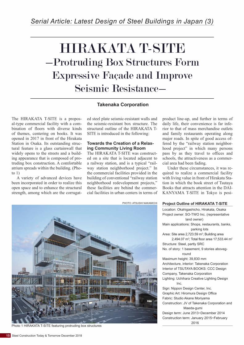
The HIRAKATA T-SITE is a propos-al-type commercial facility with a com-bination of floors with diverse kinds of themes, centering on books. It was opened in 2017 in front of the Hirakata Station in Osaka. Its outstanding struc-tural feature is a glass curtainwall that widely opens to the streets and a build-ing appearance that is composed of pro-truding box construction. A comfortable atrium spreads within the building. (Pho-to 1)
A variety of advanced devices have been incorporated in order to realize this open space and to enhance the structural strength, among which are the corrugat-
ed steel plate seismic-resistant walls and the seismic-resistant box structure. The structural outline of the HIRAKATA T-SITE is introduced in the following:
Towards the Creation of a Relax-ing Community Living RoomThe HIRAKATA T-SITE was construct-ed on a site that is located adjacent to a railway station, and is a typical “rail-way station neighborhood project.” In the commercial facilities provided in the building of conventional “railway station neighborhood redevelopment projects,” these facilities are behind the commer-cial facilities in urban centers in terms of
product line-up, and further in terms of daily life, their convenience is far infe-rior to that of mass merchandise outlets and family restaurants operating along major roads. In spite of good access of-fered by the “railway station neighbor-hood project” in which many persons pass by as they travel to offices and schools, the attractiveness as a commer-cial area had been fading.
Under these circumstances, it was re-quired to realize a commercial facility with living value in front of Hirakata Sta-tion in which the book street of Tsutaya Books that attracts attention in the DAI-KANYAMA T-SITE in Tokyo is posi-
Project Outline of HIRAKATA T-SITELocation: Okahigashicho, Hirakata, OsakaProject owner: SO-TWO Inc. (representative
land owner)Main applications: Shops, restaurants, banks,
parking lotsArea: Site area 2,723.59 m2; Building area
Serial Article: Latest Design of Steel Buildings in Japan (3)
HIRAKATA T-SITE-Protruding Box Structures Form
Expressive Façade and Improve Seismic Resistance-
Takenaka Corporation
tioned as a core facility.In order to regenerate the railway sta-
tion neighboring area, we considered that it was not only important for the HIRAKATA T-SITE project to offer at-tractive content with living value, with a book street as a core facility, but also for the community to be steadily devel-oped there, capitalizing on the living val-ue thus created. In addition, we consid-ered that what is required for producing such values is the creation of the site like a “community living room” into which local citizens freely gather together.
Building CompositionTsutaya Books has conventionally opened its bookshops in a low-rise build-ing or as a building tenant. The cur-rent HIRAKATA T-SITE is a nine-story building-type shop, a first of its kind for Tsutaya Books. As a result, a key point in the plan was how to arrange the book street that connects the upper and low-er floors of the building and how to link the book street with other streets. The fa-çade facing the station plaza is finished entirely with a glass wall so that the bus-tling atmosphere inside the building can be presented to the outside. (Photo 2)
In the HIRAKATA T-SITE building, each living proposal is treated as a vol-ume, which is not piled up straight and vertically but is piled in a shifted form like Jenga. In doing so, a comfortable two-layer atrium space is produced.
On the station front side, seven box structures protrude. Three box structures arranged on the fourth to fifth floors are composed of a two-layer atrium and the exterior walls are finished entirely with a glass curtainwall. The box structure pro-trudes into the front of the station by up to about 5 m. Its height is about 8.5 m and its width about 7.5 m, and the book-shelf arranged on the wall surface and to a full ceiling height plays a role in con-necting the upper and lower floors. (Pho-to 3)
When viewing a cross-sectional view, the two-layer atriums are arranged in the form of alternate pilings to the side of the station and to the reverse side of the sta-tion in order to provide an image as if the inside space of all of the floors are con-nected. (Fig. 1)
Every atrium is small in scale, but their linkage brings about a sense of in-tegration in construction. The priority in the structural plan of the HIRAKATA T-SITE was for every visitor to feel as if they were in their living room or home wherever they are in the HIRAKATA T-SITE.
Concept of Building AppearanceGenerally in the construction of commer-cial facilities on high-price land, because of the necessity to secure large floor plates that fully occupy the construction site, buildings with flat and wide wall ar-eas tend to be constructed. In the current project, several rooftop terraces appear on the side facing the front of the station due to the alternate piling of the volumi-nous box structures.
Then, capitalizing on rooftop terraces to be used as play areas for children and a site for restaurants and cafes, we at-tempted to produce in the front of the sta-tion a landscape where people can gath-er together. In this landscape of gathering together, it is important that the terrace can be seen from the neighboring terrace, that the eyes of people visiting for differ-ent purposes can intertwine each other, and that those who are present can feel the presence of each other. If the terraces were arranged in a linear manner along the plaza, such a condition couldn’t be brought about. Important here is that clusters of people with identical sympa-thies in terms of lifestyle can be seen by each other.
16December 2018 Steel Construction Today & Tomorrow
Fig. 1 Sectional Drawing
4,50
03,
800
3,90
04,
600
260
600
4,27
04,
500
4,50
04,
500
4,50
0
7,950 9,600 9,600
▽6FL
▽7FL
▽8FL
▽RFL
▽1FL
▽B1FL
▽2FL
▽3FL
▽4FL
▽5FL
4,50
0
ABCD
Bank
Kids floor
Beauty and life salon
Food market
Bank
Finance lounge
Restaurant
Mechanical bicycle parking lot
Rooftop plantingOutdoor equipment
Restaurant
PilotisCafé
Café
Rest space
Apple store
Terrace
Terrace
Terrace
Terrace Kids room
Finance lounge
Terrace
Living/event space
“Community living room”
Photo 3 Looking down the first-floor atrium en-trance from the third floor
Photo 2 Bustling inside the HIRAKATA T-SITE overflowing into the plaza in front of the station
PHOTO: ATSUSHI NAKAMICHI
PHOTO: TAIZO FURUKAWA
The inside space of the protruding box structures serve as a “communi-ty living room,” and the outside surface of the box structure plays a role as the wall surface of the plaza in front of the station. That is, the HIRAKATA T-SITE building itself forms part of the plaza in front of the station.
Inside of the BuildingBecause the main proposal in the proj-ect was to “create a relaxing communi-ty living room,” determining the scale of each building element was important. When the living space, visitor and book are taken into account as the main play-ers, the size of the structural members would become excessively large, and as a result it would be felt that something is wrong. For example, when the size of columns at the book street reaches 600 mm in diameter, the building construc-tion itself lacks structural balance. To solve this problem, we considered that, if the core on the east side and the box structure on the west side were treated as seismic-resistant elements and if the de-sign can be made so that the axial force is borne only by the column, the column diameter could be reduced to 300 mm or less. Finally, a column diameter of 267.4 mm was determined due to the efforts of the structural designers.
Structural PlanThe design concept of the HIRAKATA T-SITE lies in “creating a relaxing com-munity living room.” The structural de-signer understood the concept to be the “creation of a safe space where a sense of security can be obtained.” While there are buildings that demonstrate a sense of safety and security by adopting a me-ga-structure, we considered that such a system was inappropriate for the HI-RAKATA T-SITE. When examining the provision of a space that is comfortable and relaxing, it is better not to expose the building structure to the outside. To that
end, we considered it desirable not to ex-pose the structural members themselves by adopting thin, slender members.
With regard to structural safety, the client had a high interest in seismic re-sistance, and it was demanded that the seismic resistance of the HIRAKATA T-SITE be set at 1.25 times that prescribed in the Building Standard Law of Japan. In order to achieve the compatible per-formance of highly comfortable space and high seismic resistance, it was nec-essary to prepare a tenacious structural plan that makes optimum use of the nar-row space in which the structural mem-bers are arranged. An aggregate of devic-es are incorporated into the construction of the building-for example, in the con-struction of the façade, in addition to the adoption of slender structural members, some devices are used so that the slender members can demonstrate seismic resis-tance even in their use as they are.
A main seismic-resistance element adopted was the corrugated steel plate seismic-resistant wall, which was ar-ranged on the core side. While the wall causes plastic deformation during major earthquakes, it is high in fatigue strength, and thus it has a structure to function as a response-control member that absorbs seismic energy.
Seismic-resistant ElementsThe corrugated steel plate seismic-re-sistant wall is arranged on the core side. Meanwhile, in the façade on the station plaza side that widely opens to the out-
side, nearly no seismic-resistant ele-ments are arranged, which creates the risk of the whole building structure to undergo torsional behavior during earth-quakes. To remedy this, we examined whether this eccentricity could be sup-pressed by making the most of the pro-truding box structure as a seismic-resis-tant element. In order for the protruding box structure to demonstrate even a little bit of high rigidity to a seismic force that deforms the box structure to a rhombus shape, the column and beam were insert-ed into the outer frame panel of the box structure. (Photo 4)
Further, some devices were incorpo-rated to improve the rigidity of the box structure-including the adoption of concrete-filled steel tubes (CFT) for the columns that support the box structure, and an increase in the size of the periph-ery beams. (Fig. 2)
As a result, the eccentricity of the whole building structure was success-fully suppressed with no arrangement of braces or other diagonal members in the open surface on the station plaza side but by making optimum use of the box struc-tures.
The aspect width of the outer-frame finishing panel is 400 mm. In order to fit the columns and beams into this width, it was required to suppress the external width of the columns and beams to 300 mm or less for the wall surface and to 330 mm or less for the floor surface. This was an extremely high hurdle in terms of structural design.
17 Steel Construction Today & Tomorrow December 2018
Photo 4 Steel structure construction
PHOTO: TAKENAKA CORPORATION
Fig. 2 Arrangement of Steel Frame Members
Existing underground
exterior wall, bottom plate
Seismic-resistant box structure
Corrugated steel plate seismic-resistant wall
Concrete-filled steel tube (CFT) box column
Main seismic-resistant element at aboveground floors
Suppression of torsion due to maldistribution of seismic-resistant element in long-side direction
Improvement of rigidity of seismic-resistant box structure
The aspect width of the panel was im-portant for the box-shaped space of the two-layer box atrium surrounded with books. When the aspect width surpasses 400 mm, this wider size does not fit with the atrium design purpose thereby losing a sense of living. Accordingly, we asked for the structural team to by no means surpass 400 mm.
When only 300 mm was available as the width for arranging the columns, the best that could be done normally was to arrange only the columns that support the box-shaped atrium space. Howev-er, in order to improve the safety even slightly, every available device includ-ing the column fitting method was incor-porated.
Adoption of Seamless Steel Tubes for ColumnsIt was decided to adopt corner-less round steel tubes as the columns to be arranged in the center of the building because their
application not only offers a sense of structural scale but allows for the wider use of available space and brings about no danger to passing visitors. Then, in order to make the size of the tube as thin as possible, heavy-wall seamless steel tubes were selected. The outside diame-ter was unified to 267.4 mm for use in every floor, and the wall thickness of the steel tube column that support the heavi-est weight at the lowest floor was set at 55 mm. Because of its seamless finish, the tubes have no weld beads and thus are structurally fine for use as columns.
In common practice in round steel tube making, steel plates are rounded and weld-joined. When using excessive-ly heavy-wall steel plates to manufacture heavy-wall tubes, it is difficult to bend and weld them together, and thus it is not easy to manufacture steel tube columns with a heavy wall thickness but a slender diameter. On the other hand, the seamless steel tube is manufactured by piecing the center of a defect-free round billet, and thus it can be said that the seamless tube is most suitable for use for columns re-quiring heavy wall thickness but slender diameter.
The seamless steel tubes with the out-side diameter and wall thickness that we wanted to adopt was not available in the normal size range of steelmakers. How-ever, it was confirmed through negotia-tions with the manufacturer that the spec-ified size could be made available and further advance adjustments were made with a fabricator concerning to the fitting of on-site weld joints of the heavy-wall tubes, which led to successful adoption. (Photos 5~6, Fig. 3)
Among other devices incorporated in-to the construction of the building was the attachment of commonly-applied H-shapes to commonly-applied square steel tube columns.
Requests for Future Steel StructuresIt is considered that the round columns with an outside diameter of 267.4 mm used in the construction of the HIRAKA-TA T-SITE cannot easily be produced employing reinforced concrete. In oth-er words, it is the steel’s attractiveness that can realize the structural section re-quiring high strength, even by the use of comparatively small-section mem-bers. On the other hand, even when ap-plying slender steel members, there are cases in which a slender member pre-pared so finely may become unexpected-ly thick due to fire protection covering-and this would be a disappointment for us. To that end, we strongly desire that an application method be found that makes the most of the slenderness offered by the steel.
In steel products, wide-width or nar-row-width H-shapes and I-shapes are freely available, and further specified sizes can be selected from ready-made product line-up. It is possible to produce a weld built-up box steel column used in the current project and also to make the steel members slender. It is another at-tractiveness of the steel that it can wres-tle with applications in the structural sec-tions that allow for the exposed use of the steel itself and are important in terms of design. ■
18December 2018 Steel Construction Today & Tomorrow
Photo 6 Building structure employing heavy-wall seamless steel tube
PHOTO: TAKENAKA CORPORATION
Photo 5 Heavy-wall seamless steel tube used as column
PHOTO: TAKENAKA CORPORATION
Fig. 3 Arrangement of Steel Structural Members at Fourth Floor
Heavy-wall seamless steel tube
Corrugated steel plate seismic-resistant wall
Arrangement of main aboveground seismic-resistant element in the periphery of core
Adoption of slender, heavy-wall round steel tubes to lessen danger of passing visitors by making slender the column at the building center space
Simple reinforcement of connection
Development of reinforcement detail for connection between box column and H-shape beam
Maldistribution of seismic-resistant element
to treat long side-direction seismic force
The Workshop on Steel Structures in Ja-karta was held on July 19, 2018. This workshop was hosted by the Ministry of Public Works and Housing (PUPR) of Indonesia, into which the Japan Iron and Steel Federation (JISF) and Japanese So-ciety of Steel Construction (JSSC) par-ticipated as supporters.
Total participants amounted to more than 60-those working in related gov-ernment agencies and industries, and uni-versity professors. Subsequent to an open-ing address each by the Minister Economic
STEEL CONSTRUCTION TODAY & TOMORROWCommittee on Overseas Market Promotion, The Japan Iron and Steel FederationChairman (Editor): Kei Teshima
Edited by
Publ ished three t imes per year, STEEL CONSTRUCTION TODAY & TOMORROW is circulated to interested persons, companies and public organizations to promote a better understanding of steel products and their application in the construction industry. Any part of this publication may be reproduced with our permission. To download content (PDF format), please go our website at: http://www.jisf.or.jp/en/activitity/sctt/index.html. We welcome your comments about the publication and ask that you contact us at: [email protected].
Japanese Society of Steel Construction3F Aminosan Kaikan Building, 3-15-8 Nihonbashi, Chuo-ku, Tokyo 103-0027, JapanPhone: 81-3-3516-2151 Fax: 81-3-3516-2152URL http://www.jssc.or.jp/english/index.html
The Japan Iron and Steel Federation3-2-10, Nihonbashi Kayabacho, Chuo-ku, Tokyo 103-0025, JapanPhone: 81-3-3669-4815 Fax: 81-3-3667-0245URL http://www.jisf.or.jp/en/index.html
Published jointly by
Affairs of the Embassy of Japan in Indo-nesia and Director General Syarif of Con-struction Development of PUPR, sever-al lectures pertaining to steel construction were delivered by lecturers from both Japan and Indonesia. On this occasion, PUPR ex-pressed its intention to establish the Indone-sian Society of Steel Construction (ISSC) by assembling those involved in iron and steel in both the public and private sectors in Indonesia. In this regard, JSSC is expect-ed to play a role in driving the dissemina-tion of steel construction in Indonesia.
Japan’s Ministry of Economy, Trade and Industry promoted the “Project on Hu-man Resources Nurturing Support for the Introduction and Dissemination of Japan’s Disaster-prevention Steel Technologies in Indonesia” for three years from 2014. Fol-lowing this, JISF and JSSC have jointly promoted diverse projects to disseminate steel construction in Indonesia. As a link with this project, JISF and JSSC have ex-tended advice and cooperation to PUPR and other related organizations concerning the establishment of the ISSC.
The Conference and Exhibition of SEAI-SI (South East Asia Iron and Steel Insti-tute) were held on June 25~28, 2018 at the Ritz-Carlton Jakarta in Indonesia, to which the Japan Iron and Steel Federation (JISF) dispatched Chairman Kenichiro Fujimoto of JISF’s International Environ-ment Strategic Committee (Environment Div., Nippon Steel & Sumitomo Metal Corporation) to deliver a lecture.
In the Session 10B Environmental Management on the third day of Confer-ence sessions, he delivered a presenta-tion titled “Steel’s Competitiveness from the Environmental Perspective.” Specifi-cally, he introduced the Japanese steel in-dustry’s initiatives to preserve the glob-
al environment-highly-efficient CO2
emissions reduction technology and COURSE50 (CO2 Ultimate Reduction System for Cool Earth 50) and at the same time explained that steel is a very
high-performance material from the per-spective of lifecycle assessment. His pre-sentation at the SEAISI Conference was taken up in major Japanese steel press and created a lot of attention.
JISF OperationsSupport of Workshop on Steel Structures in Jakarta