45
1 Welcome!
| Date post: | 24-Mar-2019 |
| Category: |
Documents |
| Upload: | trinhquynh |
| View: | 213 times |
| Download: | 0 times |

1
Welcome!

2

3

4
The message to be sent in any communications system must be modulated n to a
carrier. Why? The carrier does just that: by using a high frequency (RF or
microwave) as a carrier, the message will travel much farther than if you tried to
send the baseband signal directly. [That's why you use the phone to call across
town, rather than just shouting].

5
Here an analog signal is depicted with noise added to the signal. Notice that in this
example, every voltage has a direct result at the output.

6
Shown is a digitally modulated representation. Notice that as long as the noise level
isn’t too high, the receiver will detect the data properly.

7
This slide is a little deceiving: the complexity of IQ demodulator is really an
illusion. The only ways of modulating a sinusoid is AM, PM or FM. IQ
modulators just do this in a more general way. The more complex hardware really
comes from requiring that the receiver know the phase and frequency of the carrier
very precisely. This is known as coherent detection.

8
Think of modulation as modification of a signal in some way that can be reliably
detected at the receiver.

9
The only difference between analog (old-fashioned) modulation and digital (new
fangled) modulation is that a digital modulation restricts the modulating baseband
signal to discrete states rather than allowing the modulating signal to take on any
value between a maximum and a minimum value.
When AM, FM or PM are used in a digital modulation scheme, the names become
ASK, FSK and PSK. The SK stand s for shift keying and is derived from an early
form of digital modulation, Morse code.

10

11
If you understand this slide, all I/Q modulation protocols are comprehensible.
On any I/Q diagram, if the signal moves toward or away from the origin radially,
the power of the signal has changed. If a signal rotates around the I/Q diagram at a
constant radius, the phase of the signal is changing (and only the phase). So AM
would be a movement radially on an I/Q diagram, PM is a rotation around the I/Q
plane. And FM will look like PM since a detected frequency different from the
carrier frequency is really a change in phase per unit time.
Remember that amplitude and phase changes are always relative to the
unmodulated carrier.

12

13
The name BPSK arises from the fact that the data is transmitted via the two (and
only two) possible phase states for the carrier (binary phase). (Does the amplitude
of the carrier change??)
SHIFT KEYING comes from Morse code which was ASK, amplitude shift keying
which means turning the amplitude on and off. Any time you see the phrase shift
keying as part of a modulation protocol, you know it's digital modulation. The shift
keying phrase implies that there are only a limited number of frequency (FSK),
phase (PSK) or amplitude (ASK) states allowed which is consistent with digital
modulation. In analog modulation, the change between phase, frequency or
amplitude states is continuous.

14
With BPSK, each phase state on the constellation diagram represents one bit, i.e.,
one bit per symbol.
What if four states were possible, not two. Now each phase state (symbol) can
represent two bits.
Given the number of symbols (S) present on an IQ diagram, the number of
bits/symbol (N) is log (base 2) of S.

15
This slide shows an example of a set of 10 bits modulated onto a QPSK geometry.
The arrow shows how the RF carrier is moving from state to state.

16
Here is an example of a Quadrature Phase Shift Keyed Modulator (QPSK) where
two separate bit streams are independently modulated and then added together. This
modulator works by adding the RF signals of two separate BPSK modulators with a
90 degree relative phase shift between them. The addition of the two modulated
carriers provides the means to transmit two bits of information encoded into the
output RF carrier. The two bits or “symbols” are still transmitted at the same rate as
the input data streams thus making this form of modulation more spectrally efficient
than BPSK modulation.
A symbol represents two or more bits.

17
Here are the I/Q modulation schemes typically found in the protocols shown on the
previous slide. Please note that companies involved in manufacturing new
communication systems investigate new and different I/Q modulation schemes all
the time. Why these are some of the more common schemes will be explained as
we go along.

18
Here we see the transitions between symbol states as the bit changes in the two
input data streams create instantaneous amplitude and phase transitions as the RF
carrier is rapidly changed between symbol states. These instantaneous changes in
the signal would require an infinite amount of signal bandwidth which is not
practical in any wireless system due to limitations in the electronics and spectrum
regulations determined by the FCC and other government agencies.
19
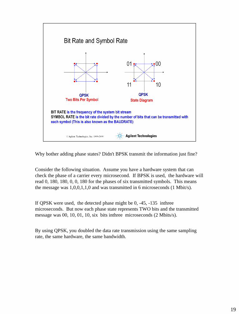
Why bother adding phase states? Didn't BPSK transmit the information just fine?
Consider the following situation. Assume you have a hardware system that can
check the phase of a carrier every microsecond. If BPSK is used, the hardware will
read 0, 180, 180, 0, 0, 180 for the phases of six transmitted symbols. This means
the message was 1,0,0,1,1,0 and was transmitted in 6 microseconds (1 Mbit/s).
If QPSK were used, the detected phase might be 0, -45, -135 inthree
microseconds. But now each phase state represents TWO bits and the transmitted
message was 00, 10, 01, 10, six bits inthree microseconds (2 Mbits/s).
By using QPSK, you doubled the data rate transmission using the same sampling
rate, the same hardware, the same bandwidth.

20
Having examined both BPSK and QPSK, you can now appreciate why most
customers want to use the highest efficiency modulation format possible.
So why doesn't everyone use 256 QAM? The answer is noise. For a given S/N
ratio, the points on a dense constellation diagram will be closer together. If the
noise environment of the transmitted signal is very bad (or there isn't a lot of signal
available), high efficiency modulation schemes lead to high BER's.
If there's lot's of power available or the noise environment can be controlled, then
high density modulation formats are used: phone lines, broadband digital and
terrestial microwave transmissions.

21

22

23
In addition to noise and distortion, the signal history of a system with finite
bandwidth will also effect its ability to transmit bits correctly.
In the ideal case, a rapidly changing voltage can reach its final value in anarbitrarily
short time. However, real signals are always time constrained in some way.
Consider a capacitive circuit charging and discharging. Depending on the time
constant of this low pass filter, if the switch opens and closes too quickly, the output
voltage may not achieve the final desired equilibrium value. If this were a digitally
modulated carrier, if the time constants of the filter were too slow to respond to the
rapidly changing bit stream, "incorrect" voltage values would be realized under
certain conditions. This is aliasing.

24
Consider these practical examples.
The first I/Q diagram is using an infinite bandwidth filter. The transitions occur in a
minimum time, but require infinite bandwidth. The second I/Q diagram is using a
Nyquist filter, so the decision points haven't moved, but the path between points is
different: instantaneous changes cannot occur.
In the third example, a non Nyquist filter is used. Now the decision points may not
occur exactly where they should (aliasing). Think of these as potential bit errors if
the spreading of the decision points becomes too severe. The gaussian filter used in
GSM, also known as GMSK, is a non Nyguist filter and this is why there are
typically multiple points at the symbol locations (aliases). For GSM, the increase in
aliasing is tolerated in order to achieve an bandwidth efficiency greater than
possible with a Nyquist filter.
25
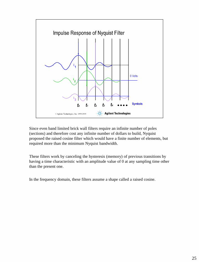
Since even band limited brick wall filters require an infinite number of poles
(sections) and therefore cost any infinite number of dollars to build, Nyquist
proposed the raised cosine filter which would have a finite number of elements, but
required more than the minimum Nyquist bandwidth.
These filters work by canceling the hysteresis (memory) of previous transitions by
having a time characteristic with an amplitude value of 0 at any sampling time other
than the present one.
In the frequency domain, these filters assume a shape called a raised cosine.

26
The deviation from a "brick walled" shape in the Nyquist filter is called the alpha
factor. The term 1+alpha represents the excess bandwidth over the minimum
Nyquist bandwidth required to transmit the signal without ISI: intersymbol
interference.
Even though the graph implies that the bandwidth is proportional to Fs/2, remember
that the upconverted signal will occupy Fs bandwidth, hence the dependence of
bandwidth on Fs, not Fs/2.

27
So what's a ROOT raised cosine filter?
The Nyquist filter can be placed either in the transmit path to filter bits before
transmission or in the receive path to filter bits after reception. The theory doesn't
care. However, if the filter is place in the transmitter only, the receiver then
operates "wide open". The noise floor in the receiver will be higher than if the
receiver was band limited.
If the transmitter doesn't have filtering, the pulse nature of a digital signal will cause
spectral spatter and potential interference with other users.
The compromise: put half the filter in the transmitter and half in the receiver. Since
serial filter responses are multiplied in the frequency domain and the desired total
filter response is a raised cosine, a root raised cosine is used in the transmitter and in
the receiver.
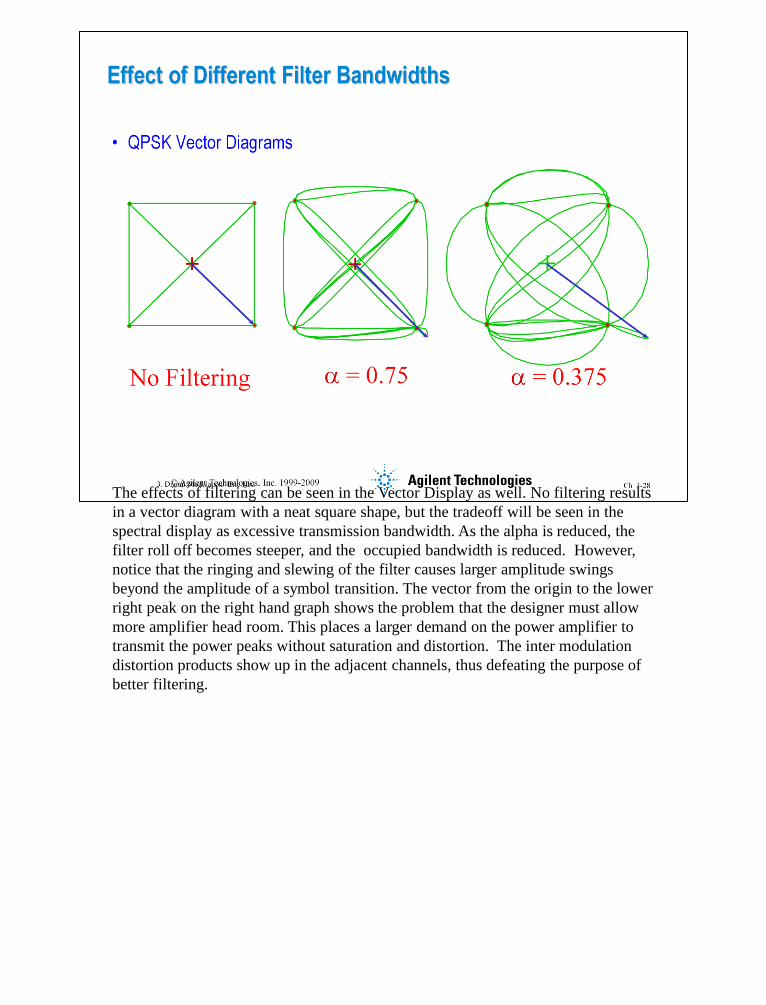
The effects of filtering can be seen in the Vector Display as well. No filtering results
in a vector diagram with a neat square shape, but the tradeoff will be seen in the
spectral display as excessive transmission bandwidth. As the alpha is reduced, the
filter roll off becomes steeper, and the occupied bandwidth is reduced. However,
notice that the ringing and slewing of the filter causes larger amplitude swings
beyond the amplitude of a symbol transition. The vector from the origin to the lower
right peak on the right hand graph shows the problem that the designer must allow
more amplifier head room. This places a larger demand on the power amplifier to
transmit the power peaks without saturation and distortion. The inter modulation
distortion products show up in the adjacent channels, thus defeating the purpose of
better filtering.

29

30
31
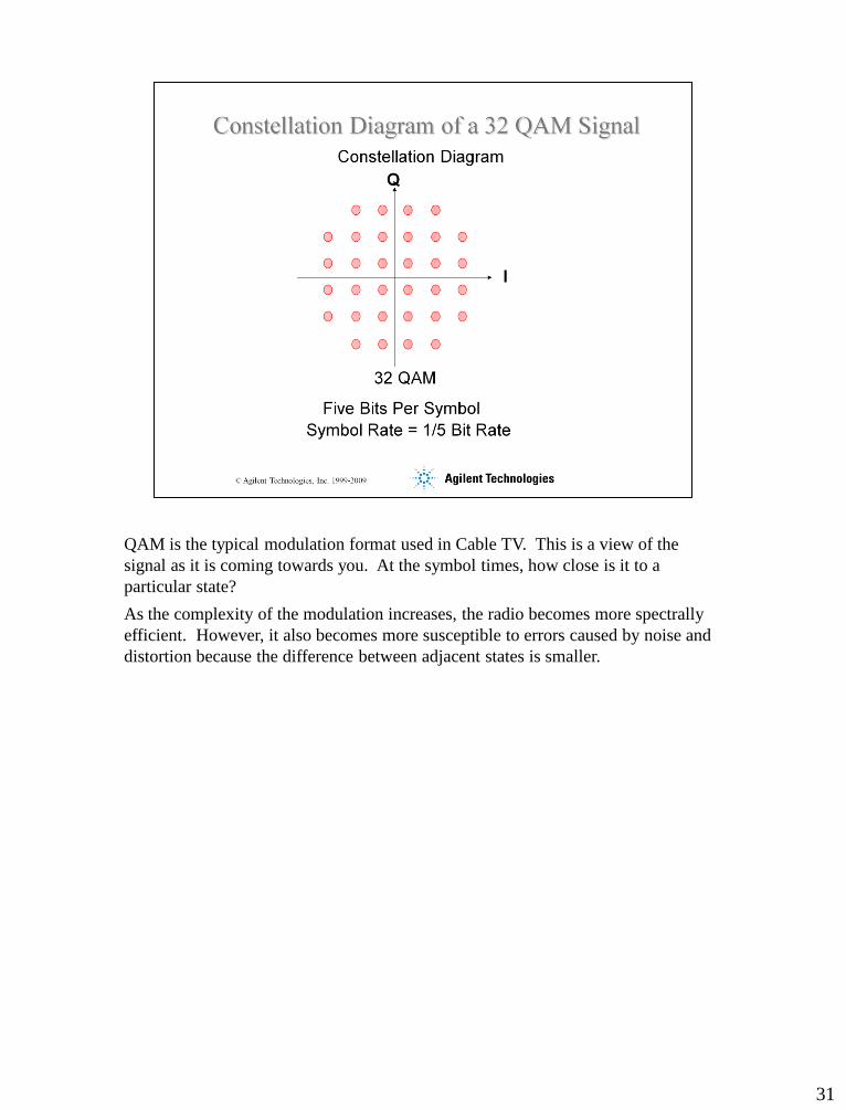
QAM is the typical modulation format used in Cable TV. This is a view of the
signal as it is coming towards you. At the symbol times, how close is it to a
particular state?
As the complexity of the modulation increases, the radio becomes more spectrally
efficient. However, it also becomes more susceptible to errors caused by noise and
distortion because the difference between adjacent states is smaller.

32
33
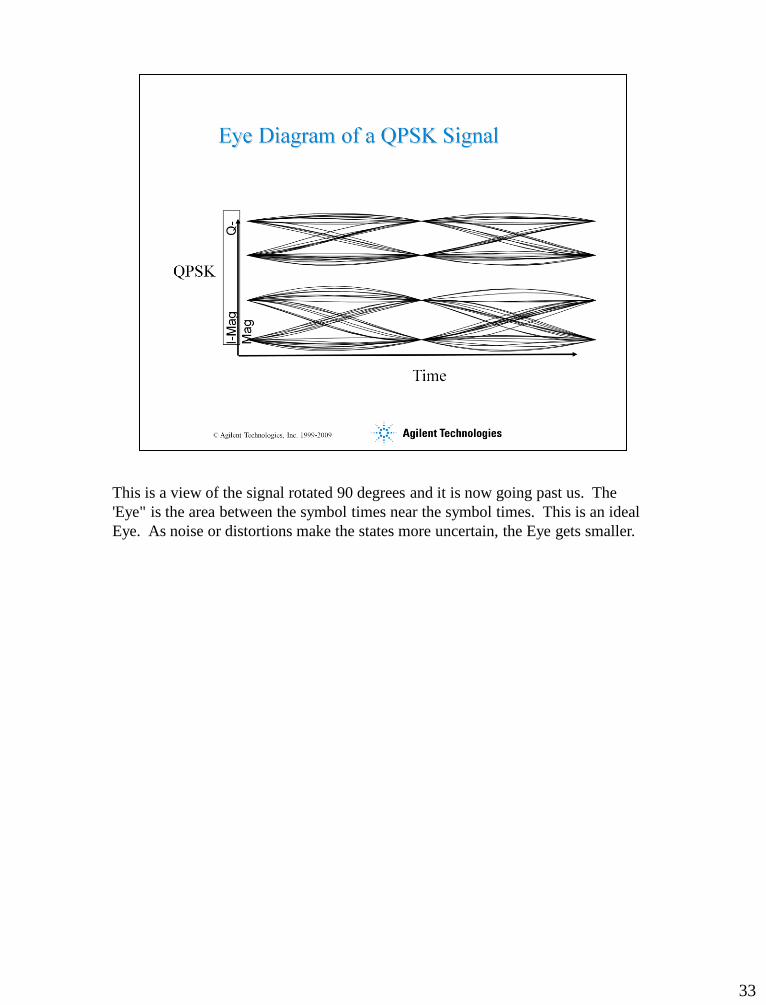
This is a view of the signal rotated 90 degrees and it is now going past us. The
'Eye" is the area between the symbol times near the symbol times. This is an ideal
Eye. As noise or distortions make the states more uncertain, the Eye gets smaller.
34
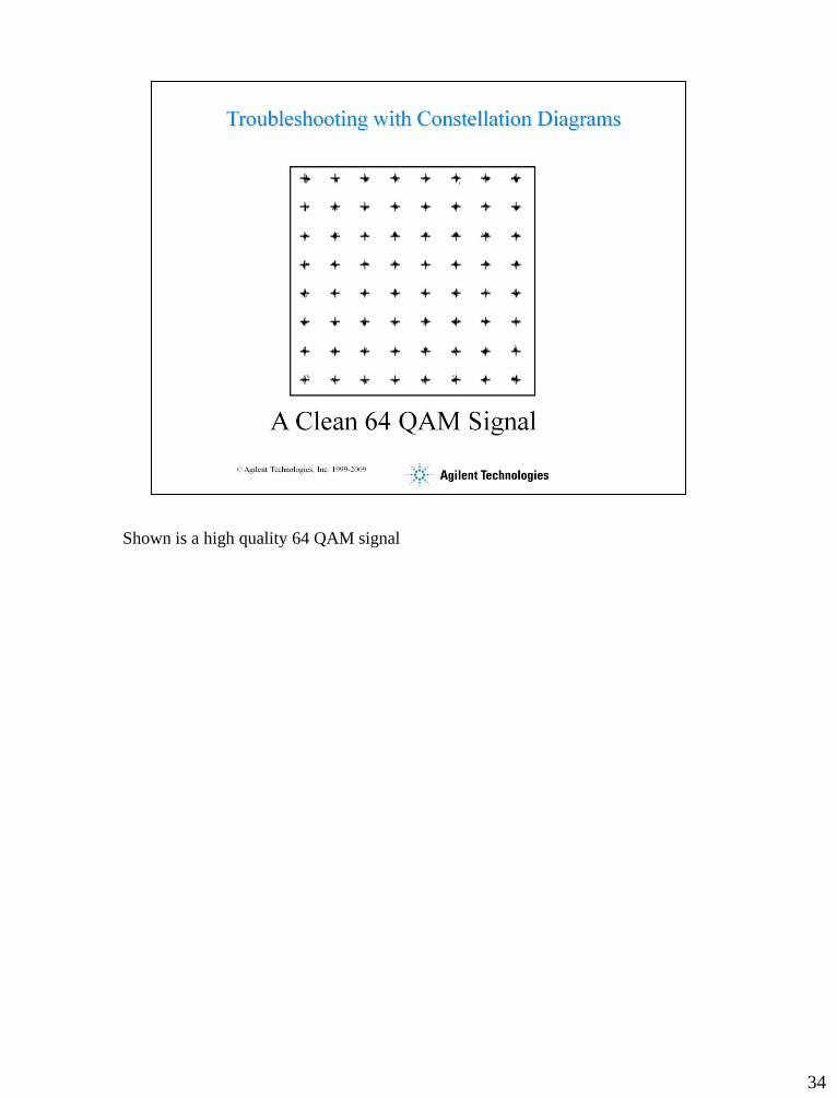
Shown is a high quality 64 QAM signal

35
Notice the effects near the edge of the IQ plane. The system is having difficulty
driving to the outer edges of the IQ plane which represents an amplifier entering
compression.

36
Notice the Q values are correct (rows) but the I values (columns) are incorrect. This
is a gain imbalance between I and Q

37
This is an interfering tone. The rotation speed of the circles represents the tone
frequency that is interfering.

38
This is a degraded signal to noise signal.

39
This has a 0 Hz or DC bias.

40
This is what phase noise looks like on a digital system.

41
Here are more typical IQ transmission impairments which can be quickly identified
by the HP 894XX.

42

43
EVM provides a way to quantify the errors in digital modulation. The error vector is
simply the difference between the actual constellation point and the reference or
ideal constellation point. Note that we measure both magnitude and phase. Both are
useful for evaluating problems.
The real value of EVM is estimating BER (bit error rate).
44
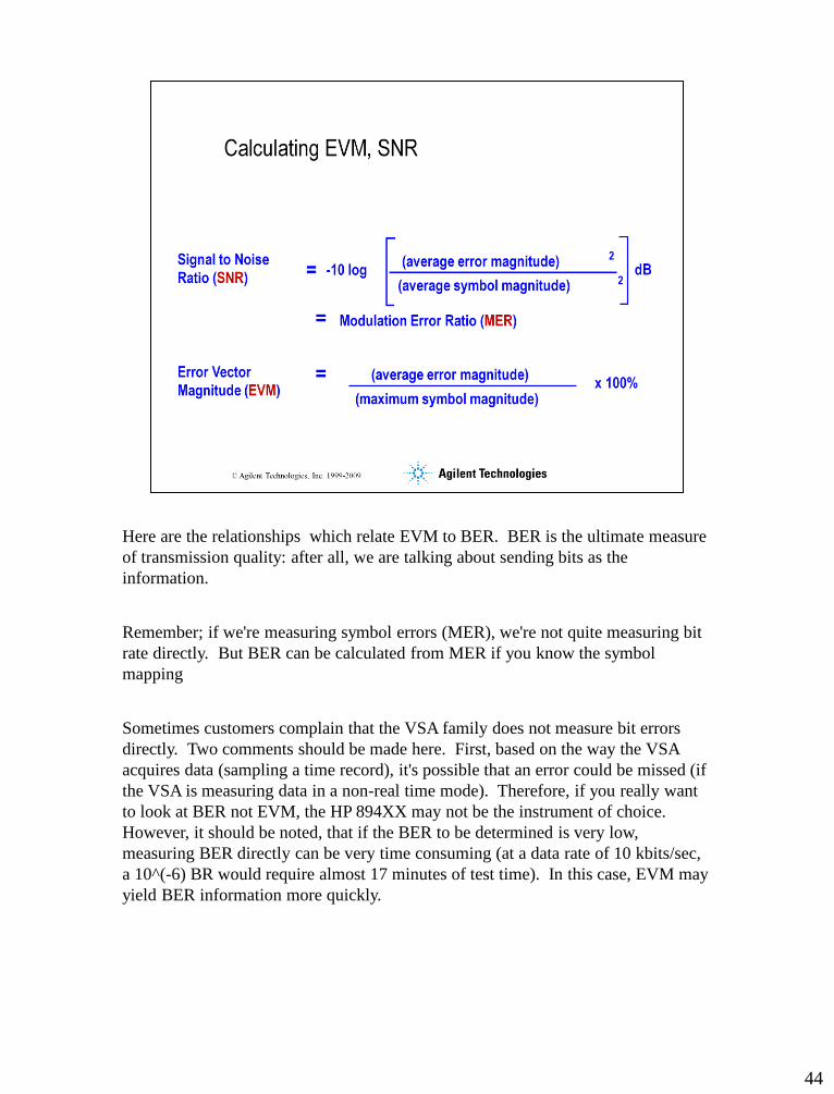
Here are the relationships which relate EVM to BER. BER is the ultimate measure
of transmission quality: after all, we are talking about sending bits as the
information.
Remember; if we're measuring symbol errors (MER), we're not quite measuring bit
rate directly. But BER can be calculated from MER if you know the symbol
mapping
Sometimes customers complain that the VSA family does not measure bit errors
directly. Two comments should be made here. First, based on the way the VSA
acquires data (sampling a time record), it's possible that an error could be missed (if
the VSA is measuring data in a non-real time mode). Therefore, if you really want
to look at BER not EVM, the HP 894XX may not be the instrument of choice.
However, it should be noted, that if the BER to be determined is very low,
measuring BER directly can be very time consuming (at a data rate of 10 kbits/sec,
a 10^(-6) BR would require almost 17 minutes of test time). In this case, EVM may
yield BER information more quickly.

45
The qualitative relationship between EVM and BER is shown here.
Consider a signal level of A volts for a BPSK signal. The nominal distance between
the two decisions points is 2*A. The blue circle represents an arbitrary noise
voltage which would begin to cause Bit errors to occur..
What signal strength is required for a QPSK signal to achieve the same BER in the
presence of the same noise level? If we maintain the 2*A symbol location
separation, the signal strength must be 1.414 V to achieve the same noise immunity.
This is 3 dB higher than the BSPK signal.
The calculation for 8PSK relative to BPSK is also shown here.


![Analog Design in Sub-100nm Technologies - IEEE Web Hostingewh.ieee.org/r5/denver/sscs/Presentations/2006_06... · 2006. 6. 27. · 4 Quotes [Vertregt, ESSCIRC 2004] "Significant power](https://static.documents.pub/doc/80x56/60bb235cb0688a03351ffed1/analog-design-in-sub-100nm-technologies-ieee-web-2006-6-27-4-quotes-vertregt.jpg)


