Knowledge Base Article Type: Instructions 3-Pic Oil Injected Vibrator Shaft Instructions for Models, 22HF, 16HF, 1600 machines WARNING Never work on, clean or service this unit, control panel or any machine or open or remove any protective cover, guard, grate, door, or maintenance panel until the power or energy sources has been turned off, locked out / tagged out, and all moving parts have come to a complete stop and or blocked to prevent movement. Machinery is dangerous – avoid personal injury and or death by following manufacture, Local, and OHSA safety procedures. Contact Columbia Machine for safety decals, guards, horns and beacons. Description: Instructions on “How to” properly install a new 3-pic vibrator half-shaft assembly into the vibrator base. Inspection of components, how to maintain, for Floor Model machines.
Transcript
Knowledge Base
Article Type: Instructions
3-Pic Oil Injected Vibrator Shaft
Instructions for Models, 22HF,
16HF, 1600 machines
WARNING Never work on, clean or service this unit, control panel or any machine or open or remove any protective cover, guard, grate, door, or maintenance panel until the power or energy sources has been turned off, locked out / tagged out, and all moving parts have come to a complete stop and or blocked to prevent movement. Machinery is dangerous – avoid personal injury and or death by following manufacture, Local, and OHSA safety procedures. Contact Columbia Machine for safety decals, guards, horns and beacons.
Description:
Instructions on “How to” properly install a new 3-pic vibrator half-shaft
assembly into the vibrator base. Inspection of components, how to maintain,
for Floor Model machines.
1
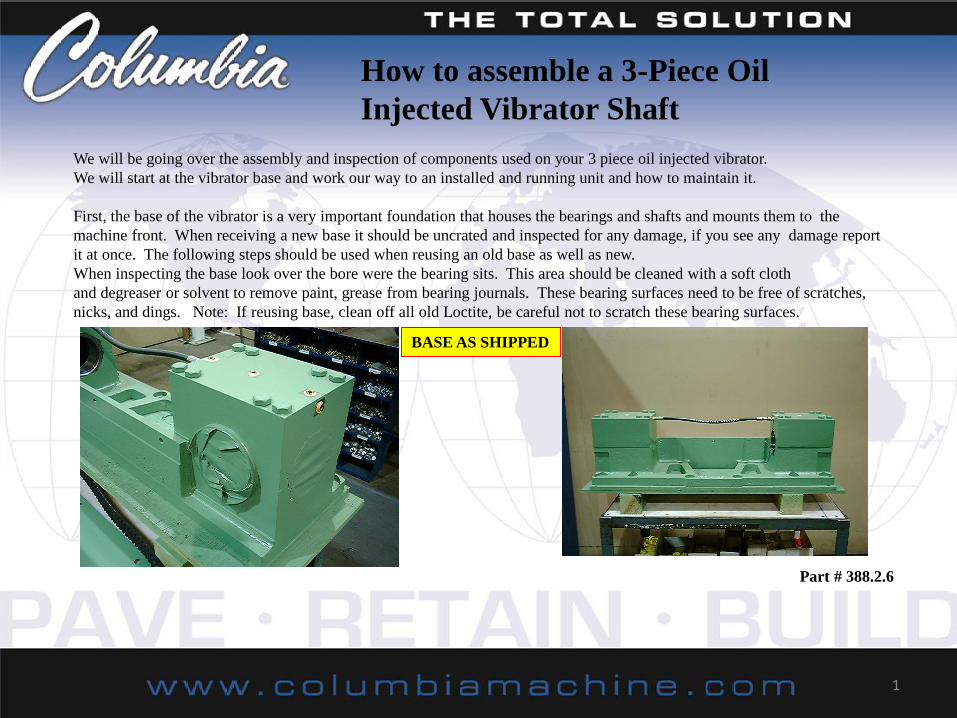
We will be going over the assembly and inspection of components used on your 3 piece oil injected vibrator.
We will start at the vibrator base and work our way to an installed and running unit and how to maintain it.
First, the base of the vibrator is a very important foundation that houses the bearings and shafts and mounts them to the
machine front. When receiving a new base it should be uncrated and inspected for any damage, if you see any damage report
it at once. The following steps should be used when reusing an old base as well as new.
When inspecting the base look over the bore were the bearing sits. This area should be cleaned with a soft cloth
and degreaser or solvent to remove paint, grease from bearing journals. These bearing surfaces need to be free of scratches,
nicks, and dings. Note: If reusing base, clean off all old Loctite, be careful not to scratch these bearing surfaces.
BASE AS SHIPPED
Part # 388.2.6
How to assemble a 3-Piece Oil
Injected Vibrator Shaft
2
NOTE: When ordering a new vibrator with shafts or a shaft ask for it to be assembled so it can be installed in one piece.
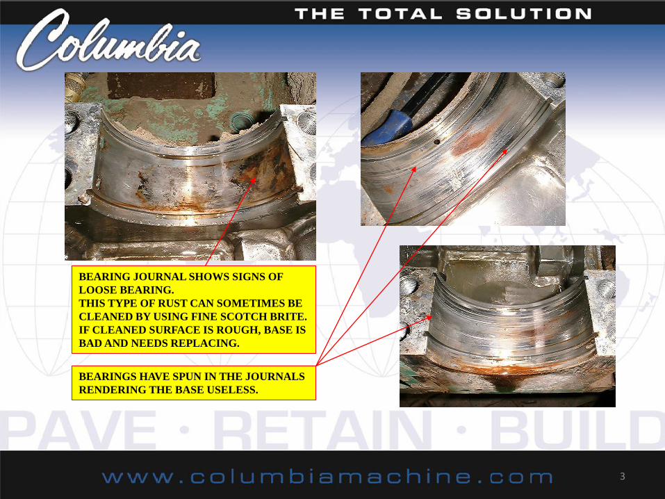
If your using the old base there are recommended areas to look over. You should inspect the bearing journal surfaces,
if there is any roughness to this surface then the base is no good and needs to be replaced. If it shows signs like the ones
Pictured below, then the base is bad and should be replaced.
DENTS IN BEARING JOURNAL RENDERS BASE USELESS.
THESE DENTS WILL CAUSE THE BEARING TO NOT BE
HELD TO SPEC AND WILL CAUSE OVER HEATING.
LOCTITE APPLIED IN BASE FRAME
BEARING JOURNALS.
THIS SHOWS TO MUCH LOC-TITE
EVEN WHEN USED IN THE CORRECT
LOCATION, THE CAP ONLY.
3
BEARING JOURNAL SHOWS SIGNS OF
LOOSE BEARING.
THIS TYPE OF RUST CAN SOMETIMES BE
CLEANED BY USING FINE SCOTCH BRITE.
IF CLEANED SURFACE IS ROUGH, BASE IS
BAD AND NEEDS REPLACING.
BEARINGS HAVE SPUN IN THE JOURNALS
RENDERING THE BASE USELESS.
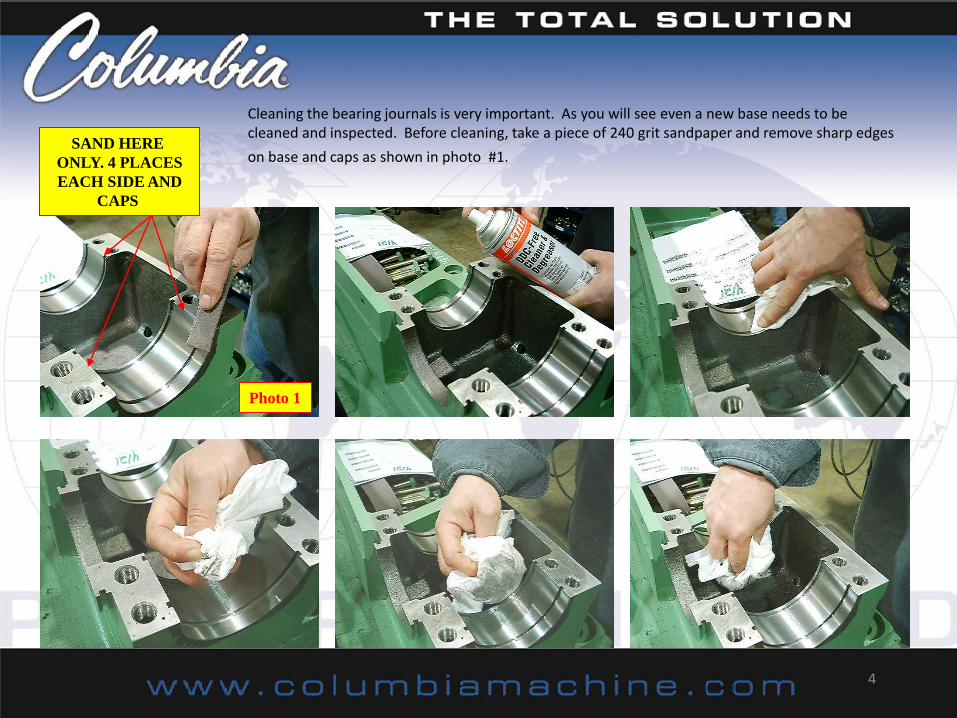
Cleaning the bearing journals is very important. As you will see even a new base needs to be cleaned and inspected. Before cleaning, take a piece of 240 grit sandpaper and remove sharp edges
on base and caps as shown in photo #1.
4
SAND HERE
ONLY. 4 PLACES
EACH SIDE AND
CAPS
Photo 1
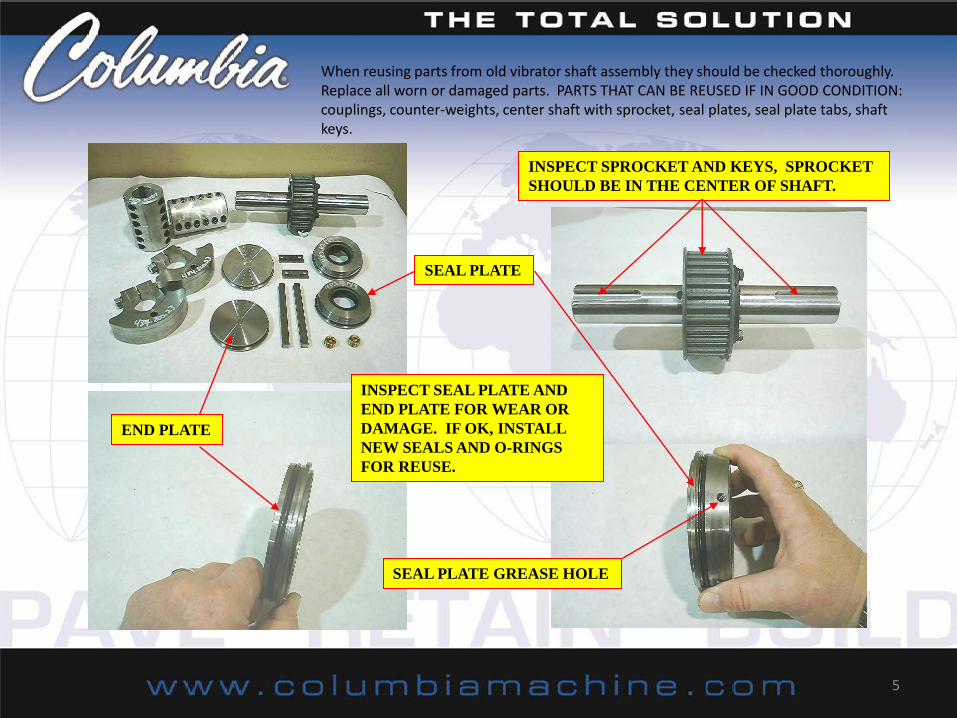
When reusing parts from old vibrator shaft assembly they should be checked thoroughly. Replace all worn or damaged parts. PARTS THAT CAN BE REUSED IF IN GOOD CONDITION: couplings, counter-weights, center shaft with sprocket, seal plates, seal plate tabs, shaft keys.
5
INSPECT SPROCKET AND KEYS, SPROCKET
SHOULD BE IN THE CENTER OF SHAFT.
INSPECT SEAL PLATE AND
END PLATE FOR WEAR OR
DAMAGE. IF OK, INSTALL
NEW SEALS AND O-RINGS
FOR REUSE.
END PLATE
SEAL PLATE
SEAL PLATE GREASE HOLE
6
DOUBLE LIP
SEAL INSIDE
SINGLE LIP SEAL
TO OUTSIDE
COUPLINGS ARE MATCH
MARKED. KEEP THEM
AS PAIRS ONLY
REPLACE BELT
BEFORE REMOVING COUNTER WEIGHT
CHECK TO MAKE SURE THERE IS A GAP
AT THE PINCH POINT. REPLACE IF
CLOSED
INSTALL SEALSWITH
A SEAL DRIVER TO
PREVENT DAMAGE
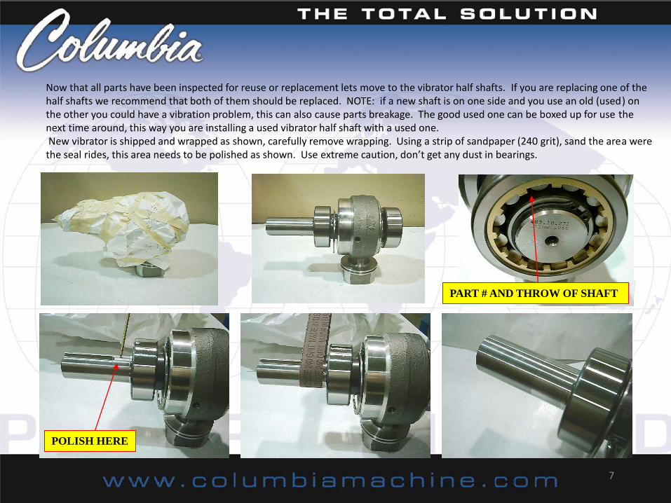
Now that all parts have been inspected for reuse or replacement lets move to the vibrator half shafts. If you are replacing one of the half shafts we recommend that both of them should be replaced. NOTE: if a new shaft is on one side and you use an old (used) on the other you could have a vibration problem, this can also cause parts breakage. The good used one can be boxed up for use the next time around, this way you are installing a used vibrator half shaft with a used one. New vibrator is shipped and wrapped as shown, carefully remove wrapping. Using a strip of sandpaper (240 grit), sand the area were the seal rides, this area needs to be polished as shown. Use extreme caution, don’t get any dust in bearings.
7
POLISH HERE
PART # AND THROW OF SHAFT
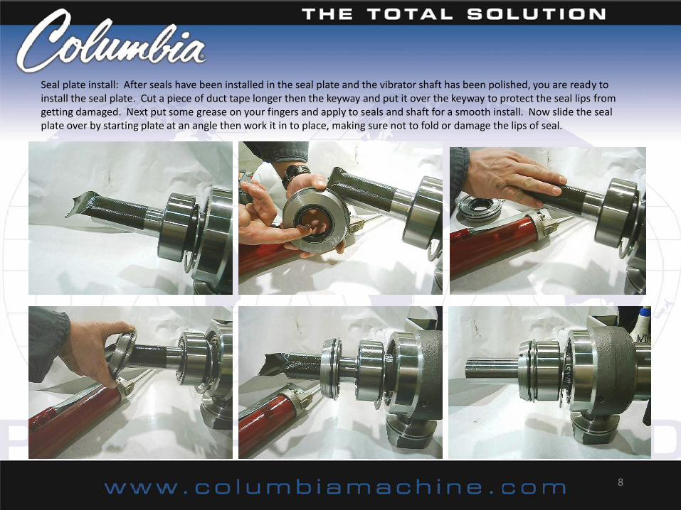
Seal plate install: After seals have been installed in the seal plate and the vibrator shaft has been polished, you are ready to install the seal plate. Cut a piece of duct tape longer then the keyway and put it over the keyway to protect the seal lips from getting damaged. Next put some grease on your fingers and apply to seals and shaft for a smooth install. Now slide the seal plate over by starting plate at an angle then work it in to place, making sure not to fold or damage the lips of seal.
8
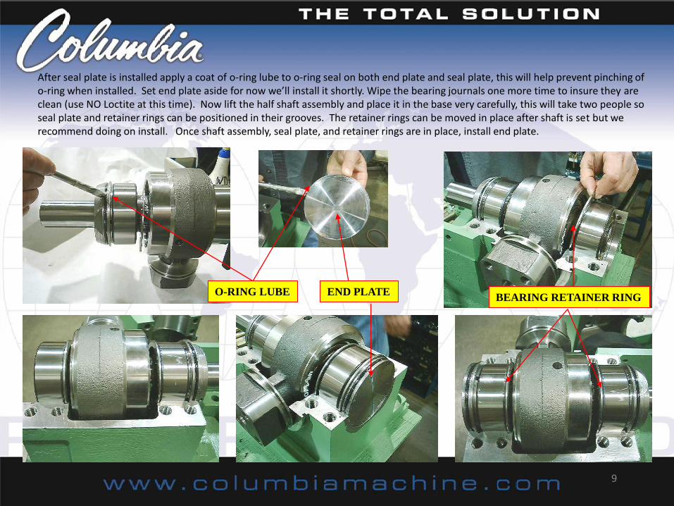
After seal plate is installed apply a coat of o-ring lube to o-ring seal on both end plate and seal plate, this will help prevent pinching of o-ring when installed. Set end plate aside for now we’ll install it shortly. Wipe the bearing journals one more time to insure they are clean (use NO Loctite at this time). Now lift the half shaft assembly and place it in the base very carefully, this will take two people so seal plate and retainer rings can be positioned in their grooves. The retainer rings can be moved in place after shaft is set but we recommend doing on install. Once shaft assembly, seal plate, and retainer rings are in place, install end plate.
9
O-RING LUBE END PLATE BEARING RETAINER RING
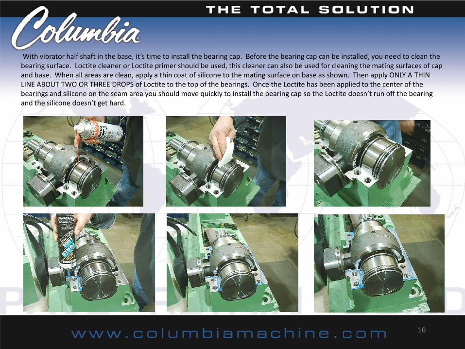
With vibrator half shaft in the base, it’s time to install the bearing cap. Before the bearing cap can be installed, you need to clean the bearing surface. Loctite cleaner or Loctite primer should be used, this cleaner can also be used for cleaning the mating surfaces of cap and base. When all areas are clean, apply a thin coat of silicone to the mating surface on base as shown. Then apply ONLY A THIN LINE ABOUT TWO OR THREE DROPS of Loctite to the top of the bearings. Once the Loctite has been applied to the center of the bearings and silicone on the seam area you should move quickly to install the bearing cap so the Loctite doesn’t run off the bearing and the silicone doesn’t get hard.
10
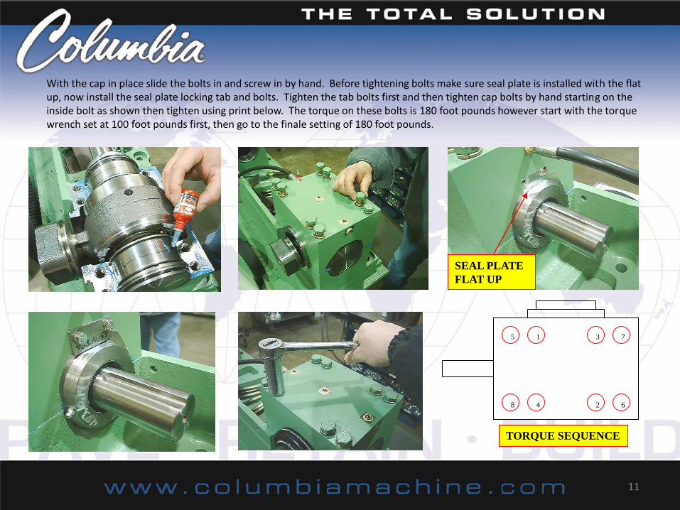
With the cap in place slide the bolts in and screw in by hand. Before tightening bolts make sure seal plate is installed with the flat up, now install the seal plate locking tab and bolts. Tighten the tab bolts first and then tighten cap bolts by hand starting on the inside bolt as shown then tighten using print below. The torque on these bolts is 180 foot pounds however start with the torque wrench set at 100 foot pounds first, then go to the finale setting of 180 foot pounds.
11
1 5 3 7
6 2 4 8
TORQUE SEQUENCE
SEAL PLATE
FLAT UP
At this point the vibrator half shaft is completely installed in the base, now we need to install the boot and springs. Here are a couple of helpful hints for an easy install. First make two handles to pull the springs together. Use a 3/8 bolt about 4 -6 inches long, then cut a piece of small wire 16 inches long. Now wrap both ends of the wire around the bolt and secure by twisting ends around main loop as shown in photo # 3. Moving on to the boot, it’s best if you turn the boot inside out as shown in the photo # 4
12
BOLT AND WIRE LOOP TOOL
PHOTO 3 PHOTO 4
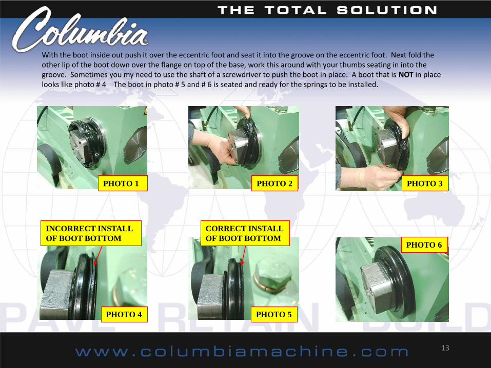
With the boot inside out push it over the eccentric foot and seat it into the groove on the eccentric foot. Next fold the other lip of the boot down over the flange on top of the base, work this around with your thumbs seating in into the groove. Sometimes you my need to use the shaft of a screwdriver to push the boot in place. A boot that is NOT in place looks like photo # 4 The boot in photo # 5 and # 6 is seated and ready for the springs to be installed.
13
PHOTO 1 PHOTO 2 PHOTO 3
PHOTO 4 PHOTO 5
PHOTO 6
INCORRECT INSTALL
OF BOOT BOTTOM
CORRECT INSTALL
OF BOOT BOTTOM
Boot spring installation: Using your bolts and wire loop tool you can install both boot retainer springs. The spring has a hook at both ends, hook the loop of the wire into the hooks as shown. Carefully pull both ends of spring up and together. Using the wire loop tool you can twist the two ends together and hook them. One of the wire loops should come off with little trouble. The other one will need to be cut to remove it. When removing the second one be very careful not to damage the boot with the sharp end of the wire. The springs should set flat in the grooves.
14
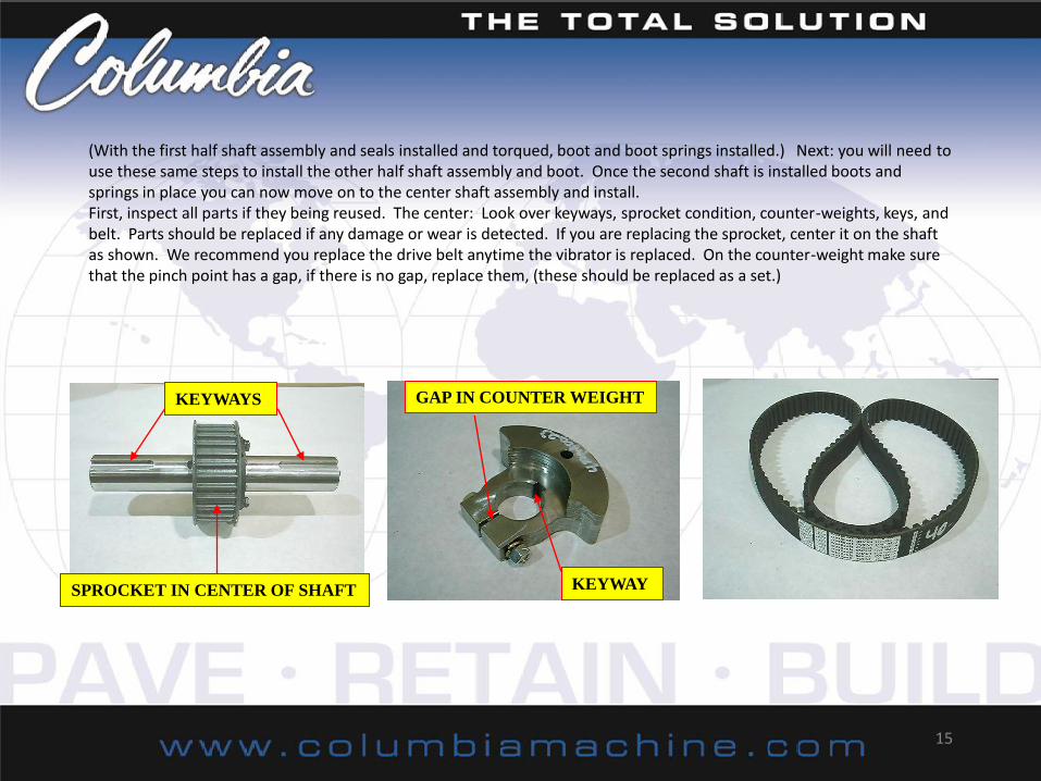
(With the first half shaft assembly and seals installed and torqued, boot and boot springs installed.) Next: you will need to use these same steps to install the other half shaft assembly and boot. Once the second shaft is installed boots and springs in place you can now move on to the center shaft assembly and install. First, inspect all parts if they being reused. The center: Look over keyways, sprocket condition, counter-weights, keys, and belt. Parts should be replaced if any damage or wear is detected. If you are replacing the sprocket, center it on the shaft as shown. We recommend you replace the drive belt anytime the vibrator is replaced. On the counter-weight make sure that the pinch point has a gap, if there is no gap, replace them, (these should be replaced as a set.)
15
KEYWAYS
SPROCKET IN CENTER OF SHAFT
GAP IN COUNTER WEIGHT
KEYWAY
Install the counter weight on the shaft. You my need to use something (like screw driver or small chisel) to open weight up and slide on shaft. Once the weight is on the shaft, measure placement. They should be the same one side to the other. Get your center shaft assembly and belt and set them in place. When installing the couplers make sure both halves match, they are match marked. Make sure the key fits tightly in both the coupling and shaft keyways, it maybe necessary to clean them up with a hand file for a good fit. Fit key into both shaft keyways. Now put the keyed half of the coupling on the shaft, then the other half and install the bolts. Hand tighten bolts making sure the two are about the same gap. Coupling bolts should be torqued to 35 foot pounds in criss-cross pattern starting from the inside out.
16
MATCH MARKS
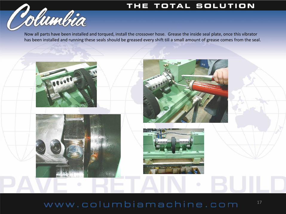
Now all parts have been installed and torqued, install the crossover hose. Grease the inside seal plate, once this vibrator has been installed and running these seals should be greased every shift till a small amount of grease comes from the seal.
17
With the vibrator completely assembled we can now move to the installation on the machine. We recommend that all bolts and washers be replaced. These bolts are a grade 8 fine thread. A very helpful thing to do is get a 6 inch or longer, up to 9 inch bolt and cut the head off, these screw in pins will act as guide dowels for the base to slide on. The face of the machine must be cleaned and tapped holes cleaned out. The cleaning process can be done with a cupped wire wheel on a DA. The wire wheel is used so you don’t damage the machined surface. The back side of the vibrator base should be deburred and cleaned.
18
Using a lifting strap wrapped around the center of the shaft, lift the assembly. Use a large crescent wrench to pivot the base 90 deg. Now line up the holes in the base with the alignment pins and push the assembly on till it bottoms out against the face of the machine. NOTE: DO NOT USE ANY LUBE ON THE BOLTS. Install all of the bolts. Start torqing from the center of the base and work to the outside in a criss-cross pattern. The ¾” needs to be torqued to 315 Foot pounds and the 1” needs torqued to 600 foot pounds. Before running Vibrator, make sure the lube pump and hoses have been completely cleaned out and new filters have been replaced. If reusing old base make sure orifice plugs (oil injectors) are clean so oil will get to the bearings. Make sure to follow the instructions for upper front end components (Shaker shafts, Died support, and parallel bars, and torquing specs to insure a long life for the vibrator.