55
Manual: 861101 Revision: F 09/08 No.28 DIPS & No.250 Fusion Machine Operator’s Manual Original Language: English
Manual: 861101 Revision: F 09/08
No.28 DIPS & No.250Fusion Machine
Operator’sManual
Original Language: English

Introduction
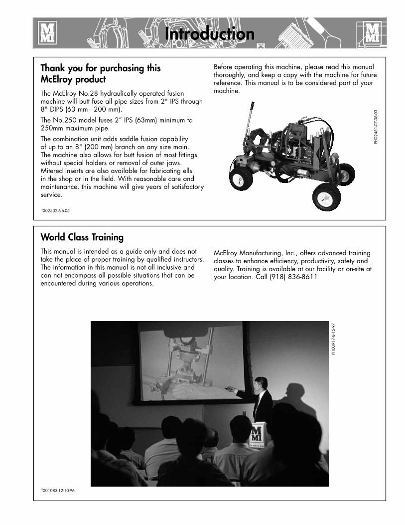
Thank you for purchasing thisMcElroy productThe McElroy No.28 hydraulically operated fusion machine will butt fuse all pipe sizes from 2" IPS through 8" DIPS (63 mm - 200 mm).
The No.250 model fuses 2” IPS (63mm) minimum to 250mm maximum pipe.
The combination unit adds saddle fusion capability of up to an 8" (200 mm) branch on any size main. The machine also allows for butt fusion of most fittings without special holders or removal of outer jaws. Mitered inserts are also available for fabricating ells in the shop or in the field. With reasonable care and maintenance, this machine will give years of satisfactory service.
Before operating this machine, please read this manual thoroughly, and keep a copy with the machine for future reference. This manual is to be considered part of your machine.
World Class TrainingThis manual is intended as a guide only and does not take the place of proper training by qualified instructors. The information in this manual is not all inclusive and can not encompass all possible situations that can be encountered during various operations.
McElroy Manufacturing, Inc., offers advanced training classes to enhance efficiency, productivity, safety and quality. Training is available at our facility or on-site at your location. Call (918) 836-8611
PH00
917-
8-15
-97
TX01083-12-10-96
TX02502-6-6-05
PH02
481-
07-0
8-03

Warranty
LIMITED WARRANTYMcElroy Manufacturing, Inc. (McElroy) warrants all products manufactured, sold and repaired by it to be free from defects in materials and workmanship, its obligation under this warranty being limited to repairing or replacing at its factory and new products, within 3 years after shipment, with the exception of purchased items (such as electronic devices, pumps, switches, etc.), in which case that manufacturer’s warranty applies. Warranty applies when returned freight is prepaid and which, upon examination, shall disclose to have been defective. This warranty does not apply to any product or component which has been repaired or altered by anyone other than McElroy or has become damaged due to misuse, negligence or casualty, or has not been operated or maintained according to McElroy’s printed instructions and warnings. This warranty is expressly in lieu of all other warranties expressed or implied. The remedies of the Buyer are the exclusive and sole remedies available and Buyer shall not be entitled to receive any incidental or consequential damages. Buyer waives the benefit of any rule that disclaimer of warranty shall be construed against McElroy and agrees that such disclaimers herein shall be construed liberally in favor of McElroy.
RETURN OF GOODSBuyer agrees not to return goods for any reason except upon the written consent of McElroy obtained in advance of such return, which consent, if given, shall specify the terms and conditions and charges upon which any such return may be made. Materials returned to McElroy, for warranty work, repair, etc., must have a Return Material Authorization (RMA) number, and be so noted on the package at time of shipment. For assistance, inquiry shall be directed to:
McElroy Manufacturing, Inc.P.O. Box 580550833 North Fulton Street Tulsa, Oklahoma 74158-0550
PHONE: (918) 836–8611, FAX: (918) 831–9285. EMAIL: [email protected]
Note: Certain repairs, warranty work, and inquiries may be directed, at McElroy’s discretion, to an authorized service center or distributor.
TX02486-04-06-05
DISCLAIMER OF LIABILITYMcElroy accepts no responsibility of liability for fusion joints. Operation and maintenance of the product is the responsibility of others. We recommend qualified joining procedures be followed when using McElroy fusion equipment.
McElroy makes no other warranty of any kind whatever, express or implied; and all implied warranties of merchantability and fitness for a particular purpose which exceed the aforestated obligation are hereby disclaimed by McElroy.
PRODUCT IMPROVEMENTMcElroy reserves the right to make any changes in or improvements on its products without incurring any liability or obligation to update or change previously sold machines and/or the accessories thereto.
INFORMATION DISCLOSEDNo information of knowledge heretofore or hereafter disclosed to McElroy in the performance of or in connection with the terms hereof, shall be deemed to be confidential or proprietary, unless otherwise expressly agreed to in writing by McElroy and any such information or knowledge shall be free from restrictions, other than a claim for patent infringement, is part of the consideration hereof.
PROPRIETARY RIGHTSAll proprietary rights pertaining to the equipment or the components of the equipment to be delivered by McElroy hereunder, and all patent rights therein, arising prior to, or in the course of, or as a result of the design or fabrication of the said product, are exclusively the property of McElroy.
LAW APPLICABLEAll sales shall be governed by the Uniform Commercial Code of Oklahoma, U.S.A.
Register your product online to activate your warranty:www.McElroy.com/fusion
(Copy information listed on the machine nameplate here for your records).
Model No.
Serial No.
Date Received
Distributor
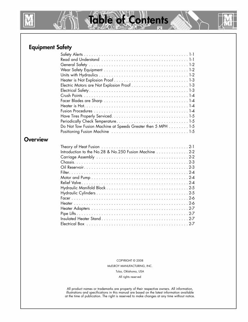
Table of Contents
Equipment SafetySafety Alerts . . . . . . . . . . . . . . . . . . . . . . . . . . . . . . . . . . . . . . . . . . 1-1Read and Understand . . . . . . . . . . . . . . . . . . . . . . . . . . . . . . . . . . . 1-1 General Safety . . . . . . . . . . . . . . . . . . . . . . . . . . . . . . . . . . . . . . . . 1-2 Wear Safety Equipment . . . . . . . . . . . . . . . . . . . . . . . . . . . . . . . . . . 1-2 Units with Hydraulics . . . . . . . . . . . . . . . . . . . . . . . . . . . . . . . . . . . . 1-2Heater is Not Explosion Proof . . . . . . . . . . . . . . . . . . . . . . . . . . . . . . 1-3 Electric Motors are Not Explosion Proof . . . . . . . . . . . . . . . . . . . . . . . 1-3 Electrical Safety . . . . . . . . . . . . . . . . . . . . . . . . . . . . . . . . . . . . . . . . 1-3 Crush Points . . . . . . . . . . . . . . . . . . . . . . . . . . . . . . . . . . . . . . . . . . 1-4Facer Blades are Sharp . . . . . . . . . . . . . . . . . . . . . . . . . . . . . . . . . . 1-4 Heater is Hot . . . . . . . . . . . . . . . . . . . . . . . . . . . . . . . . . . . . . . . . . . 1-4 Fusion Procedures . . . . . . . . . . . . . . . . . . . . . . . . . . . . . . . . . . . . . . 1-4 Have Tires Properly Serviced . . . . . . . . . . . . . . . . . . . . . . . . . . . . . . . 1-5Periodically Check Temperature . . . . . . . . . . . . . . . . . . . . . . . . . . . . . 1-5 Do Not Tow Fusion Machine at Speeds Greater then 5 MPH . . . . . . . . 1-5 Positioning Fusion Machine . . . . . . . . . . . . . . . . . . . . . . . . . . . . . . . 1-5
OverviewTheory of Heat Fusion . . . . . . . . . . . . . . . . . . . . . . . . . . . . . . . . . . . 2-1 Introduction to the No.28 & No.250 Fusion Machine . . . . . . . . . . . . . 2-2 Carriage Assembly . . . . . . . . . . . . . . . . . . . . . . . . . . . . . . . . . . . . . 2-2 Chassis . . . . . . . . . . . . . . . . . . . . . . . . . . . . . . . . . . . . . . . . . . . . . . 2-3 Oil Reservoir . . . . . . . . . . . . . . . . . . . . . . . . . . . . . . . . . . . . . . . . . . 2-3 Filter . . . . . . . . . . . . . . . . . . . . . . . . . . . . . . . . . . . . . . . . . . . . . . . . 2-4 Motor and Pump . . . . . . . . . . . . . . . . . . . . . . . . . . . . . . . . . . . . . . . 2-4 Relief Valve . . . . . . . . . . . . . . . . . . . . . . . . . . . . . . . . . . . . . . . . . . . 2-4Hydraulic Manifold Block . . . . . . . . . . . . . . . . . . . . . . . . . . . . . . . . . 2-5Hydraulic Cylinders . . . . . . . . . . . . . . . . . . . . . . . . . . . . . . . . . . . . . 2-5Facer . . . . . . . . . . . . . . . . . . . . . . . . . . . . . . . . . . . . . . . . . . . . . . . 2-6Heater . . . . . . . . . . . . . . . . . . . . . . . . . . . . . . . . . . . . . . . . . . . . . . 2-6Heater Adapters . . . . . . . . . . . . . . . . . . . . . . . . . . . . . . . . . . . . . . . 2-7Pipe Lifts . . . . . . . . . . . . . . . . . . . . . . . . . . . . . . . . . . . . . . . . . . . . . 2-7Insulated Heater Stand . . . . . . . . . . . . . . . . . . . . . . . . . . . . . . . . . . . 2-7Electrical Box . . . . . . . . . . . . . . . . . . . . . . . . . . . . . . . . . . . . . . . . . 2-7
COPYRIGHT © 2008
McELROY MANUFACTURING, INC.
Tulsa, Oklahoma, USA
All rights reserved
All product names or trademarks are property of their respective owners. All information, illustrations and specifications in this manual are based on the latest information available
at the time of publication. The right is reserved to make changes at any time without notice.
Table of Contents Butt Fusion Procedure
Read Before Operating . . . . . . . . . . . . . . . . . . . . . . . . . . . . . . . . . . 3-1Check Oil Level . . . . . . . . . . . . . . . . . . . . . . . . . . . . . . . . . . . . . . . . 3-1Connecting Machine to Power . . . . . . . . . . . . . . . . . . . . . . . . . . . . . 3-1Prepare Heater . . . . . . . . . . . . . . . . . . . . . . . . . . . . . . . . . . . . . . . . 3-2Set up Pipe Supports . . . . . . . . . . . . . . . . . . . . . . . . . . . . . . . . . . . . 3-2Install Clamping Inserts . . . . . . . . . . . . . . . . . . . . . . . . . . . . . . . . . . . 3-3Pump Motor . . . . . . . . . . . . . . . . . . . . . . . . . . . . . . . . . . . . . . . . . . 3-3Check Hydraulic Pressure . . . . . . . . . . . . . . . . . . . . . . . . . . . . . . . . . 3-4Loading Pipe Into Machine . . . . . . . . . . . . . . . . . . . . . . . . . . . . . . . . 3-5Positioning Pipe In Machine . . . . . . . . . . . . . . . . . . . . . . . . . . . . . . . 3-5Facing the Pipe . . . . . . . . . . . . . . . . . . . . . . . . . . . . . . . . . . . . . . . . 3-5Remove Facer . . . . . . . . . . . . . . . . . . . . . . . . . . . . . . . . . . . . . . . . . 3-6Position Carriage for Heater Insertion . . . . . . . . . . . . . . . . . . . . . . . . 3-7Check Heater Temperature . . . . . . . . . . . . . . . . . . . . . . . . . . . . . . . . 3-7Select the Fusion Position . . . . . . . . . . . . . . . . . . . . . . . . . . . . . . . . . 3-7Inserting Heater . . . . . . . . . . . . . . . . . . . . . . . . . . . . . . . . . . . . . . . . 3-8Heating the Pipe . . . . . . . . . . . . . . . . . . . . . . . . . . . . . . . . . . . . . . . 3-8Fusing the Pipe . . . . . . . . . . . . . . . . . . . . . . . . . . . . . . . . . . . . . . . . 3-9Opening Movable Jaws . . . . . . . . . . . . . . . . . . . . . . . . . . . . . . . . . . 3-9Opening Fixed Jaws . . . . . . . . . . . . . . . . . . . . . . . . . . . . . . . . . . . . 3-10Raise Pipe . . . . . . . . . . . . . . . . . . . . . . . . . . . . . . . . . . . . . . . . . . . . 3-10Position Pipe for Next Joint . . . . . . . . . . . . . . . . . . . . . . . . . . . . . . . . 3-10Install Next Piece of Pipe . . . . . . . . . . . . . . . . . . . . . . . . . . . . . . . . . 3-10
Special Operations - In DitchRemove Facer from Macine . . . . . . . . . . . . . . . . . . . . . . . . . . . . . . . 4-1Remove Carriage Assembly from the Chassis . . . . . . . . . . . . . . . . . . . 4-1Outrigger . . . . . . . . . . . . . . . . . . . . . . . . . . . . . . . . . . . . . . . . . . . . 4-2Remove 3-Jaw Assembly from the Carriage . . . . . . . . . . . . . . . . . . . . 4-3Manual Facer Operation . . . . . . . . . . . . . . . . . . . . . . . . . . . . . . . . . 4-4Removing Top Jaws . . . . . . . . . . . . . . . . . . . . . . . . . . . . . . . . . . . . . 4-4Lower 3-Jaw or 4-Jaw Carriage into the Ditch . . . . . . . . . . . . . . . . . . . 4-5Lower Carriage into Ditch . . . . . . . . . . . . . . . . . . . . . . . . . . . . . . . . . 4-5Clamp Carriage Assembly to Pipe . . . . . . . . . . . . . . . . . . . . . . . . . . . 4-6Make Fusion Joint . . . . . . . . . . . . . . . . . . . . . . . . . . . . . . . . . . . . . . 4-7Remove Carriage Assembly from Ditch . . . . . . . . . . . . . . . . . . . . . . . . 4-7Reassemble Fusion Machine . . . . . . . . . . . . . . . . . . . . . . . . . . . . . . . 4-7
Special Operations - Saddle Fusion ProceduresSaddle Fusion Procedure . . . . . . . . . . . . . . . . . . . . . . . . . . . . . . . . . 5-1Install Heater Adapters . . . . . . . . . . . . . . . . . . . . . . . . . . . . . . . . . . . 5-1Assure Saddle Will Fit . . . . . . . . . . . . . . . . . . . . . . . . . . . . . . . . . . . 5-1Install Clamping Inserts . . . . . . . . . . . . . . . . . . . . . . . . . . . . . . . . . . . 5-2Attach Carriage Assembly to Main . . . . . . . . . . . . . . . . . . . . . . . . . . 5-2Set Hydraulic Pressure . . . . . . . . . . . . . . . . . . . . . . . . . . . . . . . . . . . 5-2Clean Surfaces . . . . . . . . . . . . . . . . . . . . . . . . . . . . . . . . . . . . . . . . 5-2Clamp Fitting . . . . . . . . . . . . . . . . . . . . . . . . . . . . . . . . . . . . . . . . . 5-3Test for Slippage . . . . . . . . . . . . . . . . . . . . . . . . . . . . . . . . . . . . . . . 5-3Prepare Heater . . . . . . . . . . . . . . . . . . . . . . . . . . . . . . . . . . . . . . . . 5-3
Table of Contents
Special Operations - Saddle Fusion Procedures (Continued)Heat Pipe and Fitting . . . . . . . . . . . . . . . . . . . . . . . . . . . . . . . . . . . . 5-4Remove Heater . . . . . . . . . . . . . . . . . . . . . . . . . . . . . . . . . . . . . . . . 5-4Fuse Fitting to Pipe . . . . . . . . . . . . . . . . . . . . . . . . . . . . . . . . . . . . . . 5-4Allow Joint to Cool . . . . . . . . . . . . . . . . . . . . . . . . . . . . . . . . . . . . . 5-4
Special Operations - Lifting Fusion MachineHeavy Overhead Load . . . . . . . . . . . . . . . . . . . . . . . . . . . . . . . . . . . 6-1Crush Points . . . . . . . . . . . . . . . . . . . . . . . . . . . . . . . . . . . . . . . . . . 6-1Required Equipment . . . . . . . . . . . . . . . . . . . . . . . . . . . . . . . . . . . . . 6-1Install Pipe Pieces . . . . . . . . . . . . . . . . . . . . . . . . . . . . . . . . . . . . . . 6-2Ready the Unit for Lifting . . . . . . . . . . . . . . . . . . . . . . . . . . . . . . . . . 6-2Attach Slings . . . . . . . . . . . . . . . . . . . . . . . . . . . . . . . . . . . . . . . . . . 6-2Lifting Safety . . . . . . . . . . . . . . . . . . . . . . . . . . . . . . . . . . . . . . . . . . 6-2Lift Equipment . . . . . . . . . . . . . . . . . . . . . . . . . . . . . . . . . . . . . . . . . 6-3
MaintenancePreventative Maintenance . . . . . . . . . . . . . . . . . . . . . . . . . . . . . . . . . 7-1 Washing the Machine . . . . . . . . . . . . . . . . . . . . . . . . . . . . . . . . . . . 7-1 Check Hydraulic Fluid . . . . . . . . . . . . . . . . . . . . . . . . . . . . . . . . . . . 7-1Change Hydraulic Fluid and Filter . . . . . . . . . . . . . . . . . . . . . . . . . . . 7-1Check Gauge Calibration . . . . . . . . . . . . . . . . . . . . . . . . . . . . . . . . . 7-2Clean Jaws and Inserts . . . . . . . . . . . . . . . . . . . . . . . . . . . . . . . . . . . 7-2Clean Thrust Bearings . . . . . . . . . . . . . . . . . . . . . . . . . . . . . . . . . . . 7-2Clean Eyebolt Threads . . . . . . . . . . . . . . . . . . . . . . . . . . . . . . . . . . . 7-2Clean the Clamping Chains . . . . . . . . . . . . . . . . . . . . . . . . . . . . . . . 7-3Fasteners Must Be Tight . . . . . . . . . . . . . . . . . . . . . . . . . . . . . . . . . . 7-3Facer . . . . . . . . . . . . . . . . . . . . . . . . . . . . . . . . . . . . . . . . . . . . . . . 7-3Facer Blades . . . . . . . . . . . . . . . . . . . . . . . . . . . . . . . . . . . . . . . . . . 7-3Clean Heater Surfaces . . . . . . . . . . . . . . . . . . . . . . . . . . . . . . . . . . . 7-4Bleeding Air From Hydraulic System . . . . . . . . . . . . . . . . . . . . . . . . . 7-4Installing Butt Fusion Heater Plates . . . . . . . . . . . . . . . . . . . . . . . . . . . 7-5Adjusting Heater Temperature . . . . . . . . . . . . . . . . . . . . . . . . . . . . . . 7-5Heater Indicator Light . . . . . . . . . . . . . . . . . . . . . . . . . . . . . . . . . . . . 7-5
Machine Maintenance ChecklistFusion Machine Checklist . . . . . . . . . . . . . . . . . . . . . . . . . . . . . . . . . 8-1
Determining Fusion PressureDetermining Fusion Pressure . . . . . . . . . . . . . . . . . . . . . . . . . . . . . . . 9-1
Hydraulic FluidHydraulic Fluid Characteristics . . . . . . . . . . . . . . . . . . . . . . . . . . . . . 10-1
SpecificationsFusion Machine Specifications. . . . . . . . . . . . . . . . . . . . . . . . . . . . . . 11-1Generator Sizing Form . . . . . . . . . . . . . . . . . . . . . . . . . . . . . . . . . . . 11-2
TX02308-07-30-04
1 - 1
Fusion Equipment Safety
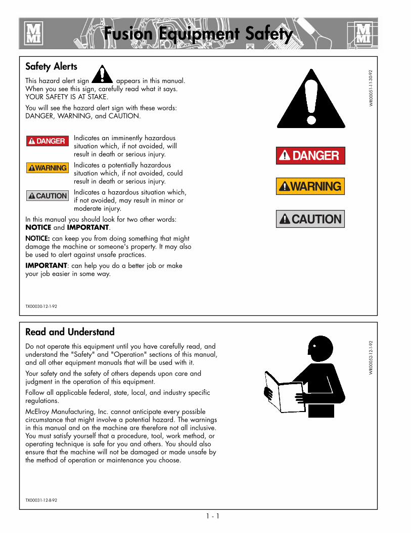
Safety AlertsThis hazard alert sign appears in this manual. When you see this sign, carefully read what it says. YOUR SAFETY IS AT STAKE.
You will see the hazard alert sign with these words: DANGER, WARNING, and CAUTION.
Indicates an imminently hazardous situation which, if not avoided, will result in death or serious injury.
Indicates a potentially hazardous situation which, if not avoided, could result in death or serious injury.
Indicates a hazardous situation which, if not avoided, may result in minor or moderate injury.
In this manual you should look for two other words: NOTICE and IMPORTANT.
NOTICE: can keep you from doing something that might damage the machine or someone's property. It may also be used to alert against unsafe practices.
IMPORTANT: can help you do a better job or make your job easier in some way.
¡PELIGRO!
Read and UnderstandDo not operate this equipment until you have carefully read, and understand the "Safety" and "Operation" sections of this manual, and all other equipment manuals that will be used with it.
Your safety and the safety of others depends upon care and judgment in the operation of this equipment.
Follow all applicable federal, state, local, and industry specific regulations.
McElroy Manufacturing, Inc. cannot anticipate every possible circumstance that might involve a potential hazard. The warnings in this manual and on the machine are therefore not all inclusive. You must satisfy yourself that a procedure, tool, work method, or operating technique is safe for you and others. You should also ensure that the machine will not be damaged or made unsafe by the method of operation or maintenance you choose.
¡PELIGRO!
WR0
0051
-11-
30-9
2W
R000
52-1
2-1-
92
TX00030-12-1-92
TX00031-12-8-92
1 - 2
Fusion Equipment Safety
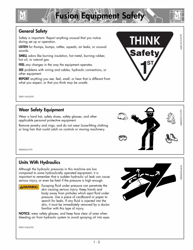
General SafetySafety is important. Report anything unusual that you notice during set up or operation.
LISTEN for thumps, bumps, rattles, squeals, air leaks, or unusual sounds.
SMELL odors like burning insulation, hot metal, burning rubber, hot oil, or natural gas.
FEEL any changes in the way the equipment operates.
SEE problems with wiring and cables, hydraulic connections, or other equipment.
REPORT anything you see, feel, smell, or hear that is different from what you expect, or that you think may be unsafe.
SAFE
1ST-1
2-22
-92
Wear Safety EquipmentWear a hard hat, safety shoes, safety glasses, and other applicable personal protective equipment.
Remove jewelry and rings, and do not wear loose-fitting clothing or long hair that could catch on controls or moving machinery.
WR0
0053
-12-
2-92
Units With HydraulicsAlthough the hydraulic pressures in this machine are low compared to some hydraulically operated equipment, it is important to remember that a sudden hydraulic oil leak can cause serious injury, or even be fatal if the pressure is high enough.
Escaping fluid under pressure can penetrate the skin causing serious injury. Keep hands and body away from pinholes which eject fluid under pressure. Use a piece of cardboard or paper to search for leaks. If any fluid is injected into the skin, it must be immediately removed by a doctor familiar with this type of injury.
NOTICE: wear safety glasses, and keep face clear of area when bleeding air from hydraulic system to avoid spraying oil into eyes.
TX00110-8-23-95
WR0
0078
-4-8
-93
TX00114-4-22-93
TX00032-4-7-93

Electric Motors are Not Explosion ProofElectric motors are not explosion proof. Operation of these components in a hazardous environment without necessary safety precautions will result in explosion and death.
When operating in a hazardous environment, keep pump motor and chassis in a safe area by using hydraulic extension hoses.
TX00424-8-12-94
Fusion Equipment Safety
¡PELIGRO! WR0
0080
-4-1
2-93
1 - 3
Electrical SafetyAlways ensure power cords are properly grounded. It is important to remember that you are working in a wet environment with electrical devices. Proper ground connections help to minimize the chances of an electric shock.
Frequently inspect electrical cords and unit for damage. Have damaged components replaced and service performed by a qualified electrician.
Do not carry electrical devices by the cord.
NOTICE: Always connect units to the proper power source as listed on the unit, or in the owner's manual. On units with two power cords, plug each cord into separate power circuits. Do not plug into both outlets of one duplex receptacle.
NOTICE: Disconnect the machine from the power source before attempting any maintenance or adjustment.
TX00105-4-12-93
WR0
0055
-4-7
-93
WR0
0025
-11-
30-9
2
Heater Is Not Explosion ProofThe heater is not explosion proof. Operaion of heter is a hazardous environment without necessary safety precautions will result in explosion and death.
If operating in a hazardous environment, the heater should be brought up to temperature in a safe environment, then unplugged before entering the hazardous atmosphere for fusion.
TX00100-9-16-94
WR0
0034
-11-
30-9
2
¡PELIGRO!
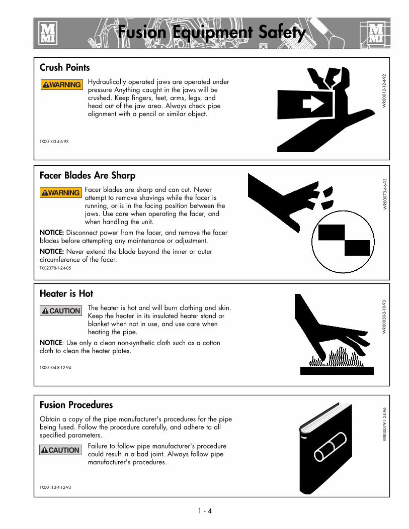
Crush PointsHydraulically operated jaws are operated under pressure Anything caught in the jaws will be crushed. Keep fingers, feet, arms, legs, and head out of the jaw area. Always check pipe alignment with a pencil or similar object.
TX00103-4-6-93
Fusion Equipment Safety
Fusion ProceduresObtain a copy of the pipe manufacturer's procedures for the pipe being fused. Follow the procedure carefully, and adhere to all specified parameters.
Failure to follow pipe manufacturer's procedure could result in a bad joint. Always follow pipe manufacturer's procedures.
TX00113-4-12-93
WR0
0079
-1-2
4-96
WR0
0012
-12-
4-92
1 - 4
Facer Blades Are SharpFacer blades are sharp and can cut. Never attempt to remove shavings while the facer is running, or is in the facing position between the jaws. Use care when operating the facer, and when handling the unit.
NOTICE: Disconnect power from the facer, and remove the facer blades before attempting any maintenance or adjustment.
NOTICE: Never extend the blade beyond the inner or outer circumference of the facer.TX02378-1-24-05
WR0
0073
-4-6
-93
Heater is HotThe heater is hot and will burn clothing and skin. Keep the heater in its insulated heater stand or blanket when not in use, and use care when heating the pipe.
NOTICE: Use only a clean non-synthetic cloth such as a cotton cloth to clean the heater plates.
TX00104-8-12-94
WR0
0030
-2-1
0-93

Fusion Equipment Safety
Have Tires Properly ServicedFailure to follow proper procedures when mounting a tire on a wheel or rim can produce an explosion which may result in serious injury or death. Have tires mounted by someone that is experienced, and has the proper equipment to perform the job safety.
TX00118-4-22-93
WR0
0083
-4-2
2-93
1 - 5
Periodically Check TemperatureNOTICE: Incorrect heating temperature can result in bad fusion joints. Check heater plate surface temperature periodically with a properly calibrated pyrometer, and make necessary adjustments.
The thermometer on heaters indicates internal temperature, and should be used as a reference only.
TX00107-11-13-95
WR0
0077
-4-1
6-93
Do Not Tow Fusion Machine at Speeds Greater than 5 MPH
The chassis is not designed for over-road towing. Towing at speeds greater than five miles per hour can result in machine damage as well as injury. Always transport the machine by flatbed truck or similar means, and make sure that unit is properly secured.
TX00101-4-12-93
CD
0018
9-1-
24-9
6
Positioning Fusion MachinePlace fusion machine on as level ground as possible, and set the brake on the rear wheel. If it is necessary to operate machine on unlevel grade, chock the wheels and block the unit to make it as stable as possible.
TX00112-9-15-94
WR0
0076
-4-7
-93
Overview
2 - 1
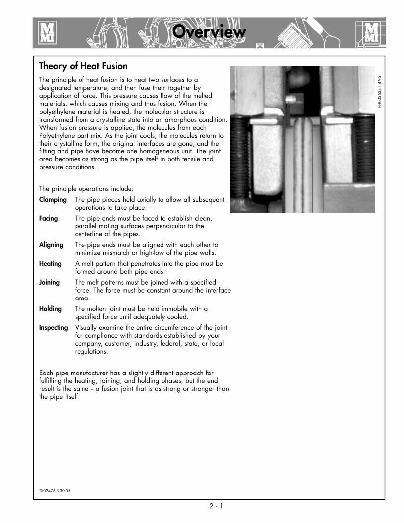
Theory of Heat FusionThe principle of heat fusion is to heat two surfaces to a designated temperature, and then fuse them together by application of force. This pressure causes flow of the melted materials, which causes mixing and thus fusion. When the polyethylene material is heated, the molecular structure is transformed from a crystalline state into an amorphous condition. When fusion pressure is applied, the molecules from each Polyethylene part mix. As the joint cools, the molecules return to their crystalline form, the original interfaces are gone, and the fitting and pipe have become one homogeneous unit. The joint area becomes as strong as the pipe itself in both tensile and pressure conditions.
The principle operations include:
Clamping The pipe pieces held axially to allow all subsequent operations to take place.
Facing The pipe ends must be faced to establish clean, parallel mating surfaces perpendicular to the centerline of the pipes.
Aligning The pipe ends must be aligned with each other to minimize mismatch or high-low of the pipe walls.
Heating A melt pattern that penetrates into the pipe must be formed around both pipe ends.
Joining The melt patterns must be joined with a specified force. The force must be constant around the interface area.
Holding The molten joint must be held immobile with a specified force until adequately cooled.
Inspecting Visually examine the entire circumference of the joint for compliance with standards established by your company, customer, industry, federal, state, or local regulations.
Each pipe manufacturer has a slightly different approach for fulfilling the heating, joining, and holding phases, but the end result is the same -- a fusion joint that is as strong or stronger than the pipe itself.
TX02476-3-30-05
PH00
363B
-1-4
-96
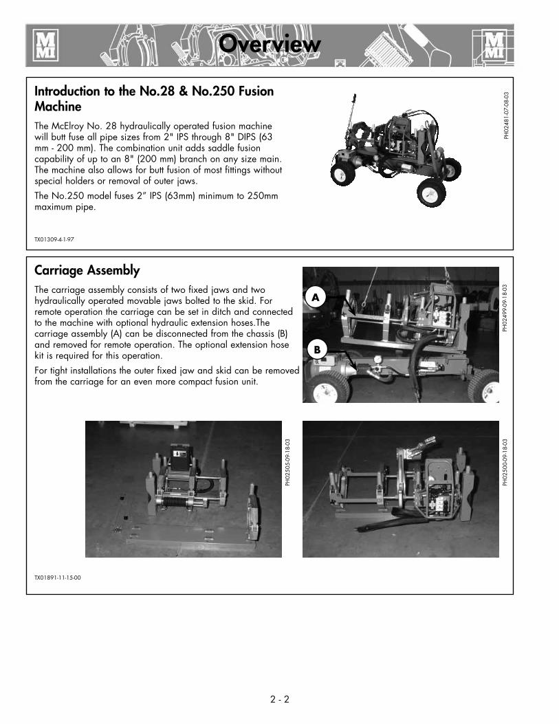
Carriage AssemblyThe carriage assembly consists of two fixed jaws and two hydraulically operated movable jaws bolted to the skid. For remote operation the carriage can be set in ditch and connected to the machine with optional hydraulic extension hoses.The carriage assembly (A) can be disconnected from the chassis (B) and removed for remote operation. The optional extension hose kit is required for this operation.
For tight installations the outer fixed jaw and skid can be removed from the carriage for an even more compact fusion unit.
TX01891-11-15-00
Overview
Introduction to the No.28 & No.250 Fusion MachineThe McElroy No. 28 hydraulically operated fusion machine will butt fuse all pipe sizes from 2" IPS through 8" DIPS (63 mm - 200 mm). The combination unit adds saddle fusion capability of up to an 8" (200 mm) branch on any size main. The machine also allows for butt fusion of most fittings without special holders or removal of outer jaws.
The No.250 model fuses 2” IPS (63mm) minimum to 250mm maximum pipe.
TX01309-4-1-97
PH02
481-
07-0
8-03
2 - 2
PH02
499-
09-1
8-03
A
B
PH02
500-
09-1
8-03
PH02
505-
09-1
8-03

Overview
ChassisThe carriage assembly is mounted on a four wheel chassis for mobility and movement along the pipe line.
There is a pinned wheel lock on the left rear wheel to prevent rolling.
The chassis is not designed for over-road towing. Towing at speeds greater than five miles per hour can result in machine damage as well as injury. Always transport the machine by flatbed truck or similar means, and make sure that unit is properly secured.
The tongue on the tow bar has a ring to slip over a ball hitch so that the machine may be conveniently maneuvered at the job site.
The tow bar acts as front pipe lift when raised.
The chassis is not designed for over-road towing.
TX02129-07-08-03
PH02
969-
3-29
-05
Oil ReservoirThe reservoir is incorporated in the chassis. The oil level should remain visible in the sight gauge in the side of the filler spout.
Never allow dirt or other foreign matter to enter the open tank.
Refer to the "Hydraulic Fluids" section of this manual for hydraulic oil recommendations.
TX00353-9-16-94PH
0248
3-07
-08-
03PH
0248
4-07
-08-
03
2 - 3

Overview
Motor and Pump The pump is powered by a TEFC capacitor start motor. The pump is a Hi/Low Gear Pump and is set to give maximum flow up to 300 psi. At this pressure, an internal sequence valve shifts to a lower flow and reduces the load on the motor.
Electric motors are not explosion proof. Operation of these components in a hazardous environment without necessary safety precautions will result in explosion and death.
Do not adjust the sequence valve (A) higher on the pump. This will overload the motor.
TX00355-11-2-94
Relief ValveThe overall system pressure is set with the relief valve (B) mounted off the pump. This pressure is set at 900 psi and is sufficient for most pipe.
When working with heavy wall pipe, it may be necessary to increase the pressure to 1200 psi for the facing operation. Reduce the pressure to 900 psi when facing is completed.
NOTICE: Prolonged operation at increased pressure can over-heat the oil.
TX02131-07-08-03
PH02
486-
07-0
8-03
PH02
487-
07-0
8-03
PH02
488-
07-0
8-03
2 - 4
¡PELIGRO!
FilterThis machine is equipped with a 10 Micron filter on the return line.
TX02132-07-08-03
PH02
485-
07-0
8-03
A
B

Overview
Hydraulic Manifold BlockMounted on this block are a carriage directional control valve, a pressure reducing selector valve, three pressure reducing valves, and a 1500 psi gauge.
A) The carriage control valve, mounted on the top of the manifold, determines whether the carriage is moving left, right, or is in neutral.
B) A 1500 psi gauge is mounted on top of the manifold.
C) The selector valve, mounted on the front of the manifold, selects a reduced pressure from one of the pressure reducing valves.
Each pressure reducing valve is labeled with a different function:
D) The top valve adjusts facing pressure to a maximum of 400 psi.
E) The middle valve adjusts heating pressure to a maximum of 400 psi.
F) The bottom valve adjusts fusion pressure to a maximum of 1500 psi.
TX02133-07-08-03
Hydraulic CylindersThe two carriage cylinders have air bleed screws and must be bled if the system ever runs low on oil or leaks air on inlet side of pump. Air in the system is indicated when carriage movement becomes jerky and erratic.
Consult the "Maintenance" section of this manual for procedure to follow when bleeding air from system.
TX01137-10-23-96
PH02
489-
07-0
8-03
PH02
490-
07-0
8-03
CD
0013
8A-9
-12-
94
2 - 5
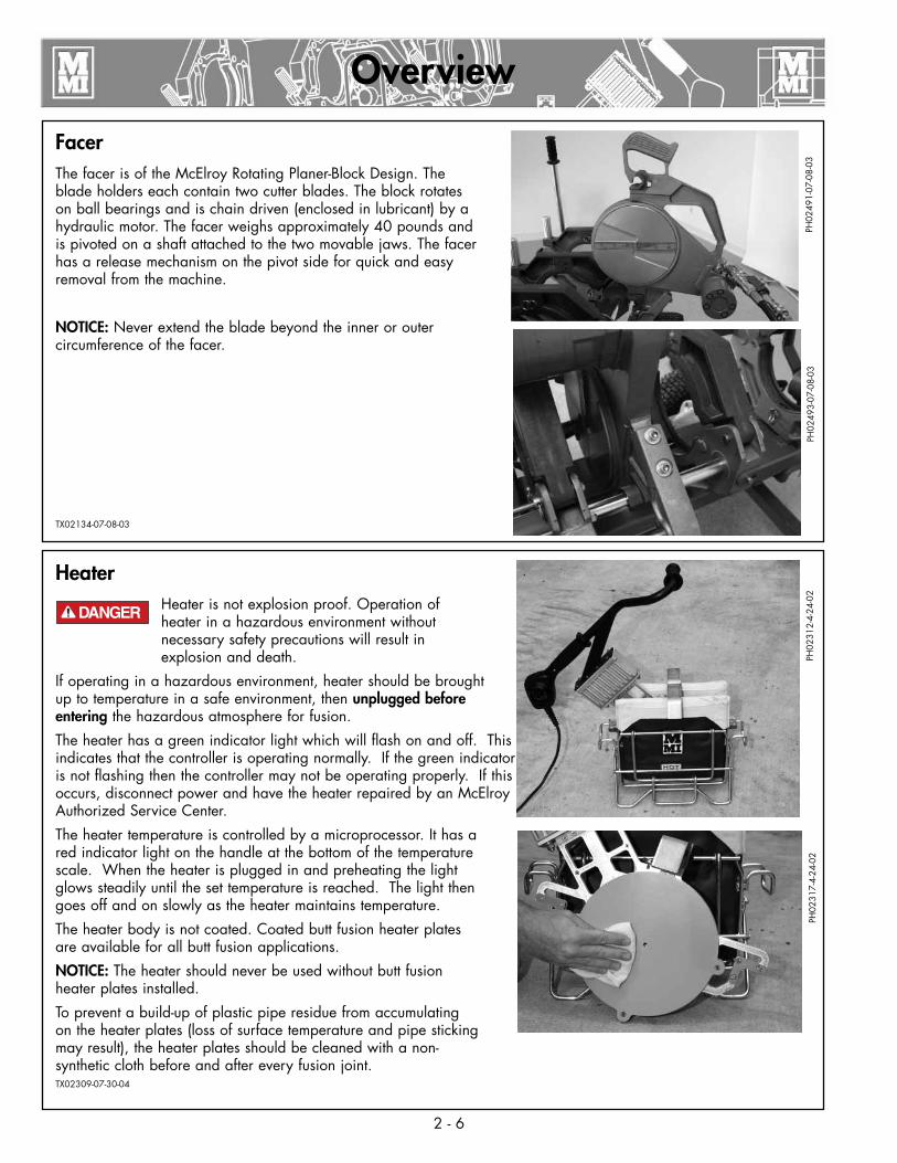
FacerThe facer is of the McElroy Rotating Planer-Block Design. The blade holders each contain two cutter blades. The block rotates on ball bearings and is chain driven (enclosed in lubricant) by a hydraulic motor. The facer weighs approximately 40 pounds and is pivoted on a shaft attached to the two movable jaws. The facer has a release mechanism on the pivot side for quick and easy removal from the machine.
NOTICE: Never extend the blade beyond the inner or outer circumference of the facer.
TX02134-07-08-03
HeaterHeater is not explosion proof. Operation of heater in a hazardous environment without necessary safety precautions will result in explosion and death.
If operating in a hazardous environment, heater should be brought up to temperature in a safe environment, then unplugged before entering the hazardous atmosphere for fusion.
The heater has a green indicator light which will flash on and off. This indicates that the controller is operating normally. If the green indicator is not flashing then the controller may not be operating properly. If this occurs, disconnect power and have the heater repaired by an McElroy Authorized Service Center.
The heater temperature is controlled by a microprocessor. It has a red indicator light on the handle at the bottom of the temperature scale. When the heater is plugged in and preheating the light glows steadily until the set temperature is reached. The light then goes off and on slowly as the heater maintains temperature.
The heater body is not coated. Coated butt fusion heater plates are available for all butt fusion applications.
NOTICE: The heater should never be used without butt fusion heater plates installed.
To prevent a build-up of plastic pipe residue from accumulating on the heater plates (loss of surface temperature and pipe sticking may result), the heater plates should be cleaned with a non-synthetic cloth before and after every fusion joint.TX02309-07-30-04
PH02
491-
07-0
8-03
PH02
312-
4-24
-02
PH02
493-
07-0
8-03
¡PELIGRO!
2 - 6
Overview
PH02
317-
4-24
-02
2 - 7
Overview
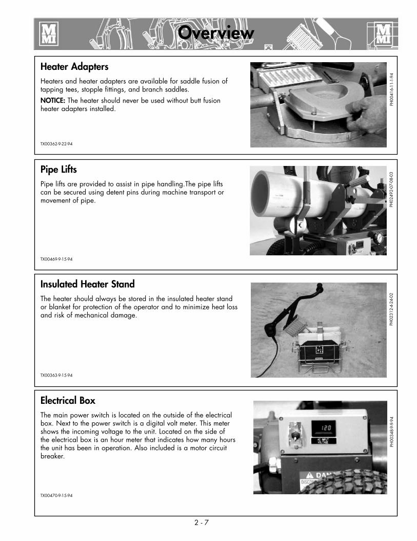
Electrical BoxThe main power switch is located on the outside of the electrical box. Next to the power switch is a digital volt meter. This meter shows the incoming voltage to the unit. Located on the side of the electrical box is an hour meter that indicates how many hours the unit has been in operation. Also included is a motor circuit breaker.
TX00470-9-15-94
Pipe LiftsPipe lifts are provided to assist in pipe handling.The pipe lifts can be secured using detent pins during machine transport or movement of pipe.
TX00469-9-15-94
Insulated Heater StandThe heater should always be stored in the insulated heater stand or blanket for protection of the operator and to minimize heat loss and risk of mechanical damage.
TX00363-9-15-94
Heater AdaptersHeaters and heater adapters are available for saddle fusion of tapping tees, stopple fittings, and branch saddles.
NOTICE: The heater should never be used without butt fusion heater adapters installed.
TX00362-9-22-94
PH00
416-
11-1
-94
PH02
492-
07-0
8-03
PH02
312-
4-24
-02
PH00
348-
9-9-
94

Check Oil LevelCheck oil level in sight gauge on filler spout and add oil if necessary.
Refer to the "Hydraulic Fluids" section of this manual for hydraulic oil recommendations.
TX00364-9-15-94
Connecting machine to PowerAll electrical equipment and power sources must be located in a nonhazardous location. Failure to do so can result in explosion and death.
Plug machine's electrical cord into a proper power source.
TX00668-10-10-95
Read Before OperatingBefore operating this machine, please read this manual thoroughly, and keep a copy with the machine for future reference.
Return manual to the protective storage box when not in use.This manual is to be consideredpart of your machine.
TX00401-9-15-94
Butt Fusion Procedure
STO
P-12
-22-
92
3 - 1
PH02
483-
07-0
8-03
PH00
348-
9-12
-94
¡PELIGRO!
Set up Pipe SupportsSet up pipe stands and adjust height so the pipe is in line with the jaws.
TX00367-9-15-94
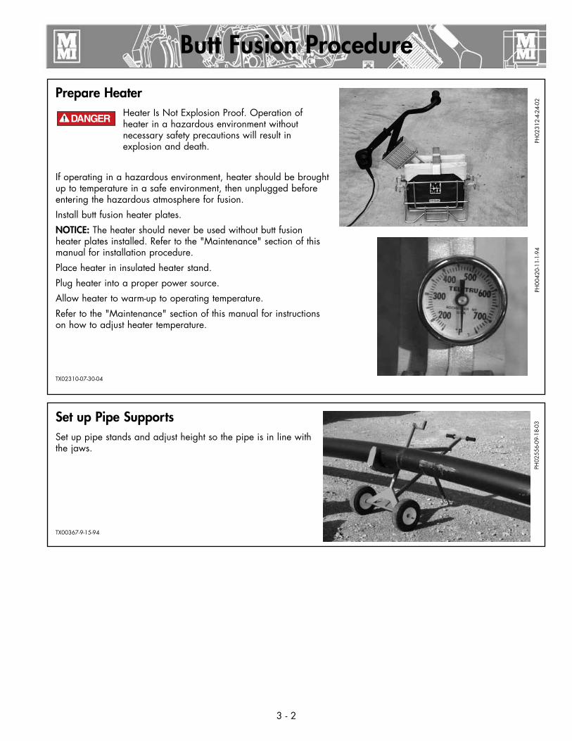
Prepare HeaterHeater Is Not Explosion Proof. Operation of heater in a hazardous environment without necessary safety precautions will result in explosion and death.
If operating in a hazardous environment, heater should be brought up to temperature in a safe environment, then unplugged before entering the hazardous atmosphere for fusion.
Install butt fusion heater plates.
NOTICE: The heater should never be used without butt fusion heater plates installed. Refer to the "Maintenance" section of this manual for installation procedure.
Place heater in insulated heater stand.
Plug heater into a proper power source.
Allow heater to warm-up to operating temperature.
Refer to the "Maintenance" section of this manual for instructions on how to adjust heater temperature.
TX02310-07-30-04
Butt Fusion Procedure
PH02
312-
4-24
-02
3 - 2
PH02
556-
09-1
8-03
¡PELIGRO!
PH00
420-
11-1
-94
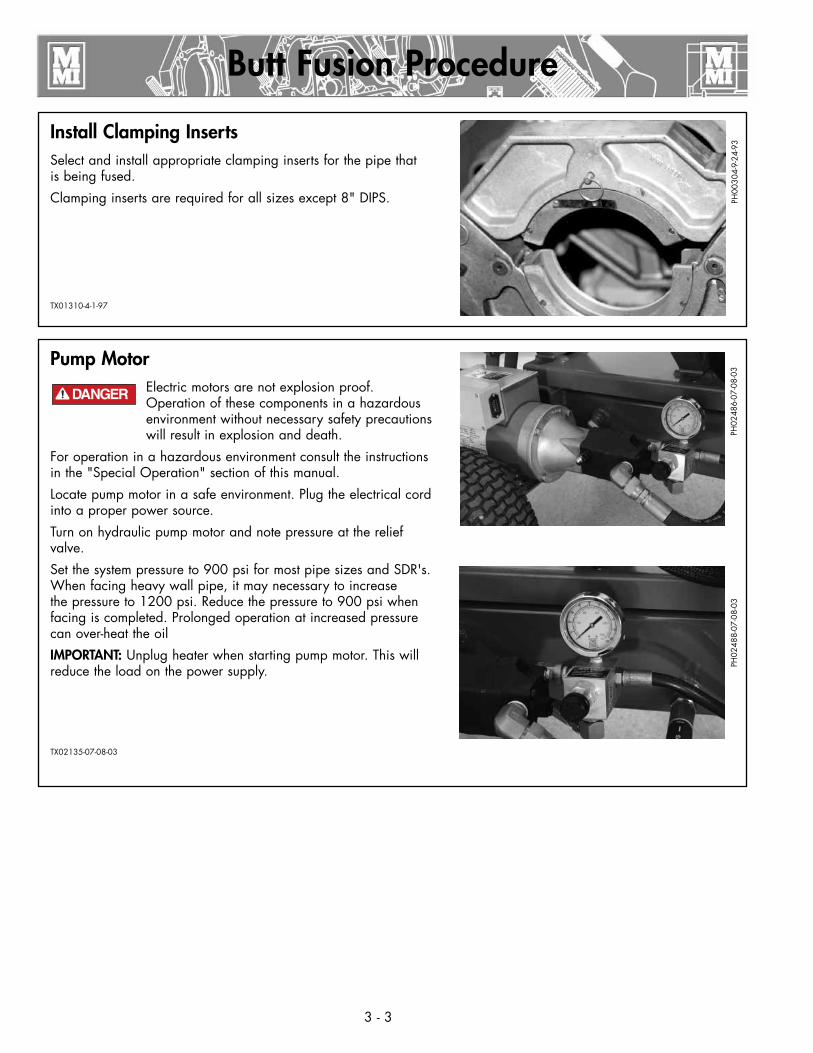
Pump MotorElectric motors are not explosion proof. Operation of these components in a hazardous environment without necessary safety precautions will result in explosion and death.
For operation in a hazardous environment consult the instructions in the "Special Operation" section of this manual.
Locate pump motor in a safe environment. Plug the electrical cord into a proper power source.
Turn on hydraulic pump motor and note pressure at the relief valve.
Set the system pressure to 900 psi for most pipe sizes and SDR's. When facing heavy wall pipe, it may necessary to increase the pressure to 1200 psi. Reduce the pressure to 900 psi when facing is completed. Prolonged operation at increased pressure can over-heat the oil
IMPORTANT: Unplug heater when starting pump motor. This will reduce the load on the power supply.
TX02135-07-08-03
Install Clamping InsertsSelect and install appropriate clamping inserts for the pipe that is being fused.
Clamping inserts are required for all sizes except 8" DIPS.
TX01310-4-1-97
Butt Fusion Procedure
PH00
304-
9-24
-93
3 - 3
PH02
486-
07-0
8-03
PH02
488-
07-0
8-03
¡PELIGRO!
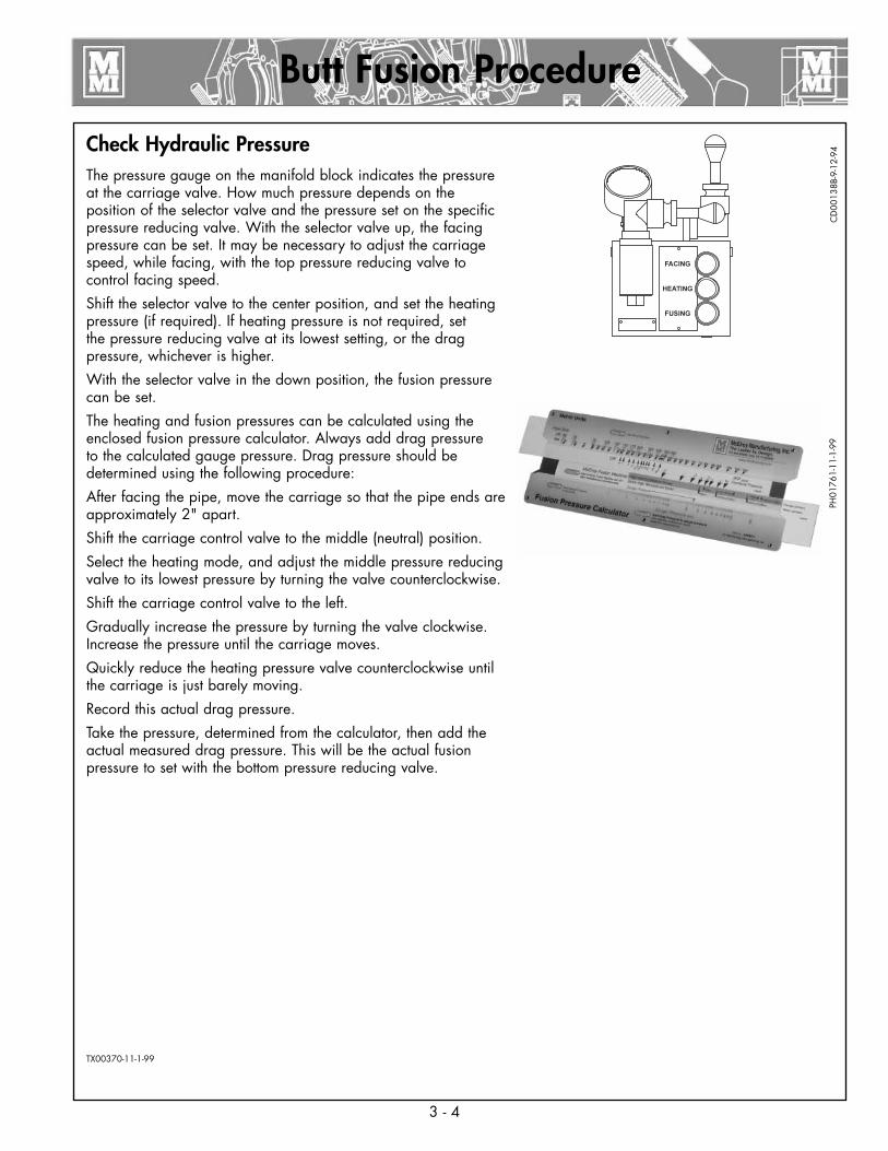
Check Hydraulic PressureThe pressure gauge on the manifold block indicates the pressure at the carriage valve. How much pressure depends on the position of the selector valve and the pressure set on the specific pressure reducing valve. With the selector valve up, the facing pressure can be set. It may be necessary to adjust the carriage speed, while facing, with the top pressure reducing valve to control facing speed.
Shift the selector valve to the center position, and set the heating pressure (if required). If heating pressure is not required, set the pressure reducing valve at its lowest setting, or the drag pressure, whichever is higher.
With the selector valve in the down position, the fusion pressure can be set.
The heating and fusion pressures can be calculated using the enclosed fusion pressure calculator. Always add drag pressure to the calculated gauge pressure. Drag pressure should be determined using the following procedure:
After facing the pipe, move the carriage so that the pipe ends are approximately 2" apart.
Shift the carriage control valve to the middle (neutral) position.
Select the heating mode, and adjust the middle pressure reducing valve to its lowest pressure by turning the valve counterclockwise.
Shift the carriage control valve to the left.
Gradually increase the pressure by turning the valve clockwise. Increase the pressure until the carriage moves.
Quickly reduce the heating pressure valve counterclockwise until the carriage is just barely moving.
Record this actual drag pressure.
Take the pressure, determined from the calculator, then add the actual measured drag pressure. This will be the actual fusion pressure to set with the bottom pressure reducing valve.
TX00370-11-1-99
Butt Fusion Procedure
CD
0013
8B-9
-12-
94
3 - 4
PH01
761-
11-1
-99

Positioning Pipe In MachineSwing the facer into place. With the carriage control valve lever, move the carriage toward the fixed jaws, while watching the gap at each end of the facer rest buttons. When the pipe is in contact with the facer, this gap indicates the amount of material that will be trimmed from the pipe end. Assure sufficient material will be removed for a complete face off. Tighten the clamp knobs on the outside jaws. Hand tighten the inside clamp knobs.
TX00372-9-15-94
Facing the PipeMove the carriage to the right.
Open the ball valve on the facer motor.
Assure the selector valve handle is up in the facing position.
Move the carriage control valve to the left.
If the facer stalls, adjust the facing pressure so the facer continues to cut.
IMPORTANT: When facing heavy wall pipe, it may be necessary to increase the system pressure to 1200 psi.
IMPORTANT: When drag pressure exceeds 300 psi it is necessary to move the carriage to the left bringing the pipe ends into contact with the facer before opening the facer valve.
Let the carriage bottom out on facer stops. Turn facer off. Move the carriage to the right so the facer can be removed.
TX02136-07-08-03
Loading Pipe Into MachineClean the inside and outside of pipe ends that are to be fused.
Open the upper jaws and insert pipe in each pair of jaws with applicable inserts installed. Let the ends of the pipe protrude about 1" past the face of the jaws.
TX00371-9-15-94
Butt Fusion Procedure
ph00
306-
9-24
-93
3 - 5
PH00
355-
9-9-
94PH
0249
4-07
-08-
03PH
0035
9-9-
12-9
4

Remove FacerRelease the trigger lock, and swing the facer out to the storage position.
Remove chips from pipe ends.
Do not touch faced pipe ends.
Inspect both pipe ends for complete face off. If the face off is incomplete, return to Loading Pipe into Machine.
Move the carriage to the left until ends of pipe butt together.
Check pipe joint for proper alignment.
Do not use finger to check for hi/lo (misalignment). The unit is under pressure, and slippage could result in crushed fingers. Always keep hands clear of the jaw area.
If pipe is not lined up, tighten the high side jaw to bring into alignment.
IMPORTANT: Always tighten the side that is higher, never loosen the low side.
When the pipe is properly aligned tighten outside clamps to insure against slippage.
Ensure there is no unacceptable gap between the pipe ends. If there is an unacceptable gap, return to Loading Pipe into Machine.
NOTICE: When clamping, do not over-tighten the clamp knobs because machine damage can result. Check to see if there is space between the upper and lower jaws. If the two jaws are touching, do not continue to tighten.
Bring the pipe ends together under fusion pressure to check for slippage. If slippage occurs, return to Loading Pipe into Machine.
TX00373-10-12-95
Butt Fusion Procedure
PH00
362-
9-14
-94
3 - 6
PH00
366-
9-12
-94
PH00
357-
9-12
-94
PH00
323-
9-25
-93
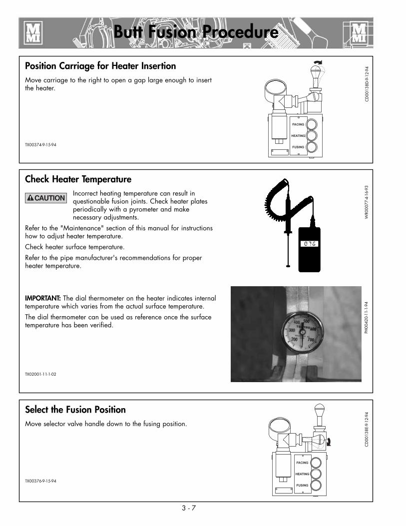
Check Heater TemperatureIncorrect heating temperature can result in questionable fusion joints. Check heater plates periodically with a pyrometer and make necessary adjustments.
Refer to the "Maintenance" section of this manual for instructions how to adjust heater temperature.
Check heater surface temperature.
Refer to the pipe manufacturer's recommendations for proper heater temperature.
IMPORTANT: The dial thermometer on the heater indicates internal temperature which varies from the actual surface temperature.
The dial thermometer can be used as reference once the surface temperature has been verified.
TX02001-11-1-02
Select the Fusion PositionMove selector valve handle down to the fusing position.
TX00376-9-15-94
Position Carriage for Heater InsertionMove carriage to the right to open a gap large enough to insert the heater.
TX00374-9-15-94
Butt Fusion Procedure
CD
0013
8D-9
-12-
94
3 - 7
WR0
0077
-4-1
6-93
CD
0013
8E-9
-12-
94PH
0042
0-11
-1-9
4
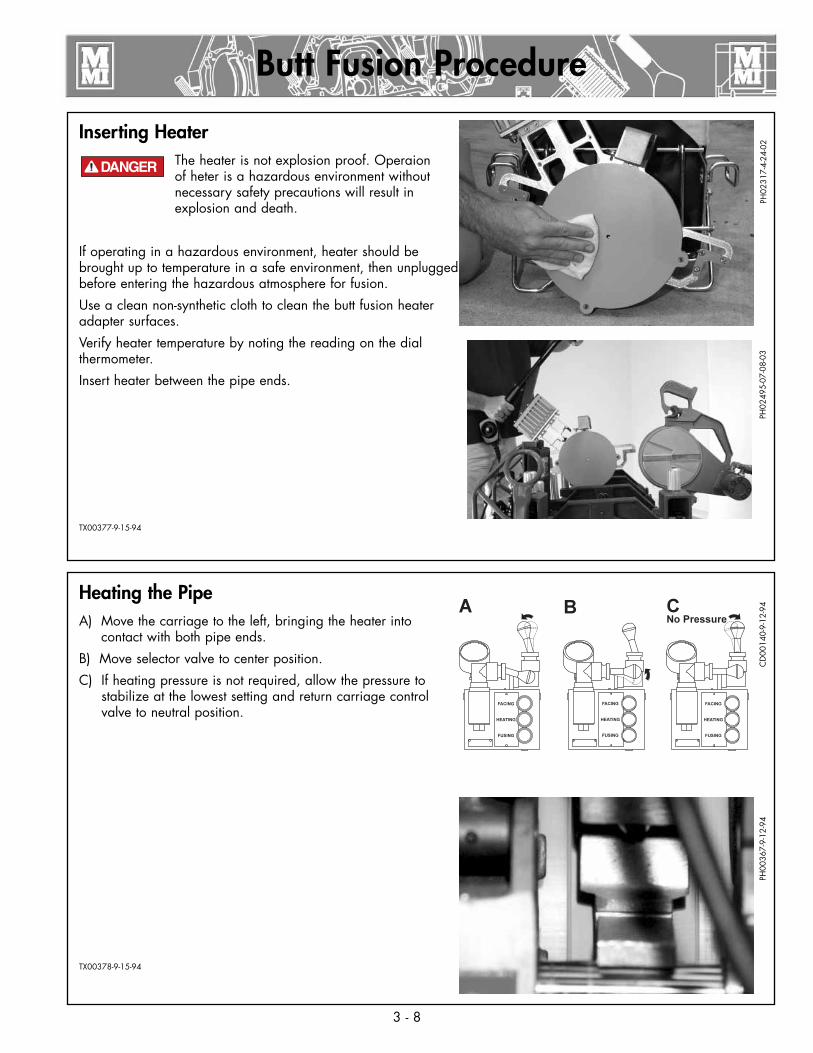
Heating the Pipe A) Move the carriage to the left, bringing the heater into
contact with both pipe ends.
B) Move selector valve to center position.
C) If heating pressure is not required, allow the pressure to stabilize at the lowest setting and return carriage control valve to neutral position.
TX00378-9-15-94
Inserting HeaterThe heater is not explosion proof. Operaion of heter is a hazardous environment without necessary safety precautions will result in explosion and death.
If operating in a hazardous environment, heater should be brought up to temperature in a safe environment, then unplugged before entering the hazardous atmosphere for fusion.
Use a clean non-synthetic cloth to clean the butt fusion heater adapter surfaces.
Verify heater temperature by noting the reading on the dial thermometer.
Insert heater between the pipe ends.
TX00377-9-15-94
Butt Fusion Procedure
PH02
317-
4-24
-02
3 - 8
CD
0014
0-9-
12-9
4
¡PELIGRO!
PH02
495-
07-0
8-03
PH00
367-
9-12
-94

Opening Movable JawsAfter the joint has cooled for the pipe manufacturer's recommended time, shift the carriage control valve to the neutral position.
Loosen all clamp knobs, and move carriage to the right far enough to open the jaw nearest the facer.
Open the movable jaws.
TX00380-9-15-94
Fusing the PipeFailure to follow pipe manufacturer's heating time, pressure, and cooling time may result in a bad joint.
After following the pipe manufacturer's suggested heating procedure:
A) Shift carriage control valve to neutral position, if it is not already in that position.
B) Shift the selector valve down to fusion position.
C) Move the carriage to the right just enough to remove the heater.
Quickly remove the heater.
D) Quickly move the carriage to the left, bringing the pipe ends together under the pipe manufacturer's recommended pressure.
Allow joint to cool under pressure according to pipe manufacturer's recommendation.
TX02313-07-30-04
Butt Fusion Procedure
3 - 9
PH02
318-
4-24
-02
PH00
363-
9-12
-94
CD
0014
1B-9
-12-
94C
D00
141A
-9-1
2-94
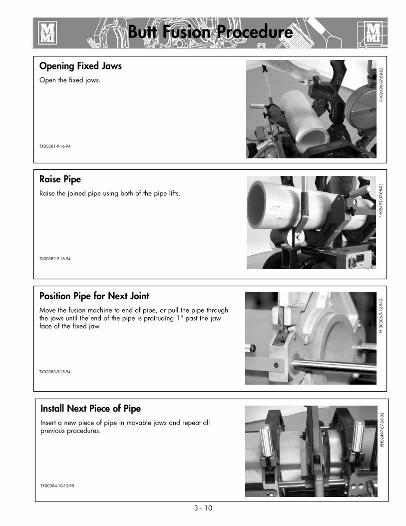
Raise PipeRaise the joined pipe using both of the pipe lifts.
TX00382-9-16-94
Position Pipe for Next JointMove the fusion machine to end of pipe, or pull the pipe through the jaws until the end of the pipe is protruding 1" past the jaw face of the fixed jaw.
TX00383-9-15-94
Opening Fixed JawsOpen the fixed jaws.
TX00381-9-16-94
Butt Fusion Procedure
PH02
496-
07-0
8-03
3 - 10
PH02
492-
07-0
8-03
PH00
306-
9-12
-940
Install Next Piece of PipeInsert a new piece of pipe in movable jaws and repeat all previous procedures.
TX00384-10-12-95
PH02
497-
07-0
8-03

Remove Facer From MachineLoosen facer locking bolts.
Lift facer out of the carriage and set on cardboard or wood blocks off of the ground.
Remove rear guide rod bracket.
Attach rear guide rod bracket in the position shown.
TX02217-09-18-03
Special Operations - In Ditch
PH00
383-
9-15
-94
4 - 1
PH01
980-
11-1
5-01
PH01
981-
11-1
5-01
Remove Carriage Assembly from the ChassisThis equipment is not explosion proof. Operation of this equipment in a hazardous environment without necessary safety precautions will result in explosion and death. See safety section.
The carriage can be easily removed from the machine for fusing pipe on the ground or in the ditch. For especially tight conditions it is also possible to remove the outer fixed jaws and skid. The facer can be removed from the pivot shaft and used manually.
Remove Pin.
Attach lifting sling to the lifting points and the manifold bracket, then lift the carriage assembly.
TX01876-11-15-00
PH02
500-
07-0
8-03
PH02
499-
07-0
8-03
¡PELIGRO!
PH02
501-
07-0
8-03

OutriggerThe outrigger is an arm that is retractable and adds support to the carriage assembly when opening the jaws and pivoting the facer away from the carriage.
To extend or retract the outrigger, press the locking button near the base of the outrigger and push or pull the arm until the button snaps to the locked position.
NOTICE: Never use the outrigger to lift or move the carriage.
TX02304-04-29-04
PH02
698-
04-2
9-04
PH02
699-
04-2
9-04
Special Operations - In Ditch
4 - 2
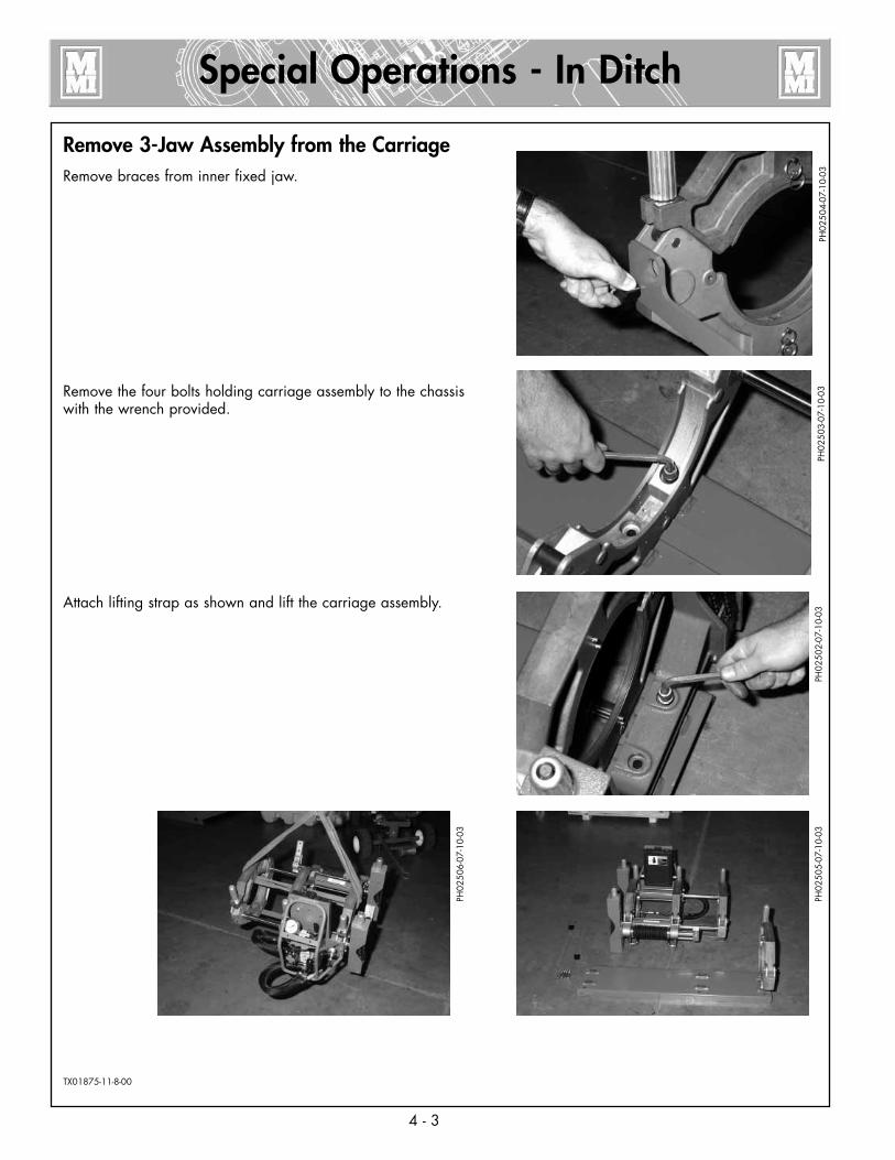
Remove 3-Jaw Assembly from the CarriageRemove braces from inner fixed jaw.
Remove the four bolts holding carriage assembly to the chassis with the wrench provided.
Attach lifting strap as shown and lift the carriage assembly.
TX01875-11-8-00
PH02
504-
07-1
0-03
Special Operations - In Ditch
4 - 3
PH02
503-
07-1
0-03
PH02
502-
07-1
0-03
PH02
505-
07-1
0-03
PH02
506-
07-1
0-03
4 - 4
Special Operations - In Ditch
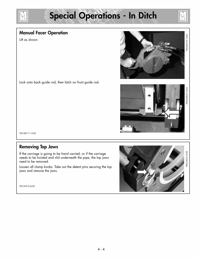
Manual Facer OperationLift as shown.
Lock onto back guide rod, then latch on front guide rod.
TX01887-11-15-00
PH02
507-
07-1
0-03
PH02
508-
07-1
0-03
Removing Top JawsIf the carriage is going to be hand carried, or if the carriage needs to be hoisted and slid underneath the pipe, the top jaws need to be removed.
Loosen all clamp knobs. Take out the detent pins securing the top jaws and remove the jaws.
TX01479-2-26-98PH
0130
5-3-
12-9
8
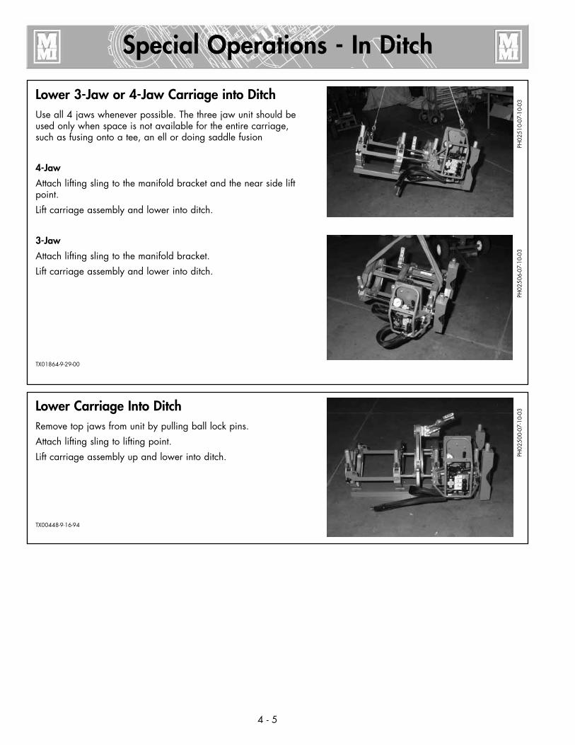
Lower 3-Jaw or 4-Jaw Carriage into DitchUse all 4 jaws whenever possible. The three jaw unit should be used only when space is not available for the entire carriage, such as fusing onto a tee, an ell or doing saddle fusion
4-Jaw
Attach lifting sling to the manifold bracket and the near side lift point.
Lift carriage assembly and lower into ditch.
3-Jaw
Attach lifting sling to the manifold bracket.
Lift carriage assembly and lower into ditch.
TX01864-9-29-00
Special Operations - In Ditch
PH02
510-
07-1
0-03
4 - 5
PH02
506-
07-1
0-03
Lower Carriage Into DitchRemove top jaws from unit by pulling ball lock pins.
Attach lifting sling to lifting point.
Lift carriage assembly up and lower into ditch.
TX00448-9-16-94PH
0250
0-07
-10-
03

Clamp Carriage Assembly to PipePosition carriage assembly on side of the pipe. Lift pipe and slide carriage assembly under pipe.
Rotate carriage assembly around to a normal upright position.
Attach the top jaws and loosely clamp around pipe.
TX00879-2-19-96
CD
0019
3b-2
-19-
96C
D00
194b
-2-1
9-96
CD
0019
5a-2
-19-
96
Special Operations - In Ditch
4 - 6
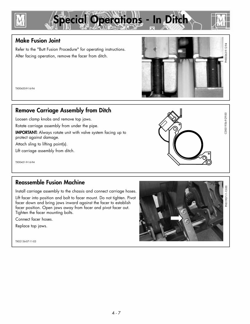
Make Fusion JointRefer to the "Butt Fusion Procedure" for operating instructions.
After facing operation, remove the facer from ditch.
TX00450-9-16-94
Special Operations - In Ditch
PH00
363-
9-12
-94
4 - 7
Remove Carriage Assembly from DitchLoosen clamp knobs and remove top jaws.
Rotate carriage assembly from under the pipe.
IMPORTANT: Always rotate unit with valve system facing up to protect against damage.
Attach sling to lifting point(s).
Lift carriage assembly from ditch.
TX00451-9-16-94
CD
0019
3b-9
-29-
00
Reassemble Fusion MachineInstall carriage assembly to the chassis and connect carriage hoses.
Lift facer into position and bolt to facer mount. Do not tighten. Pivot facer down and bring jaws inward against the facer to establish facer position. Open jaws away from facer and pivot facer out. Tighten the facer mounting bolts.
Connect facer hoses.
Replace top jaws.
TX02136-07-11-03
PH01
907-
11-1
5-00
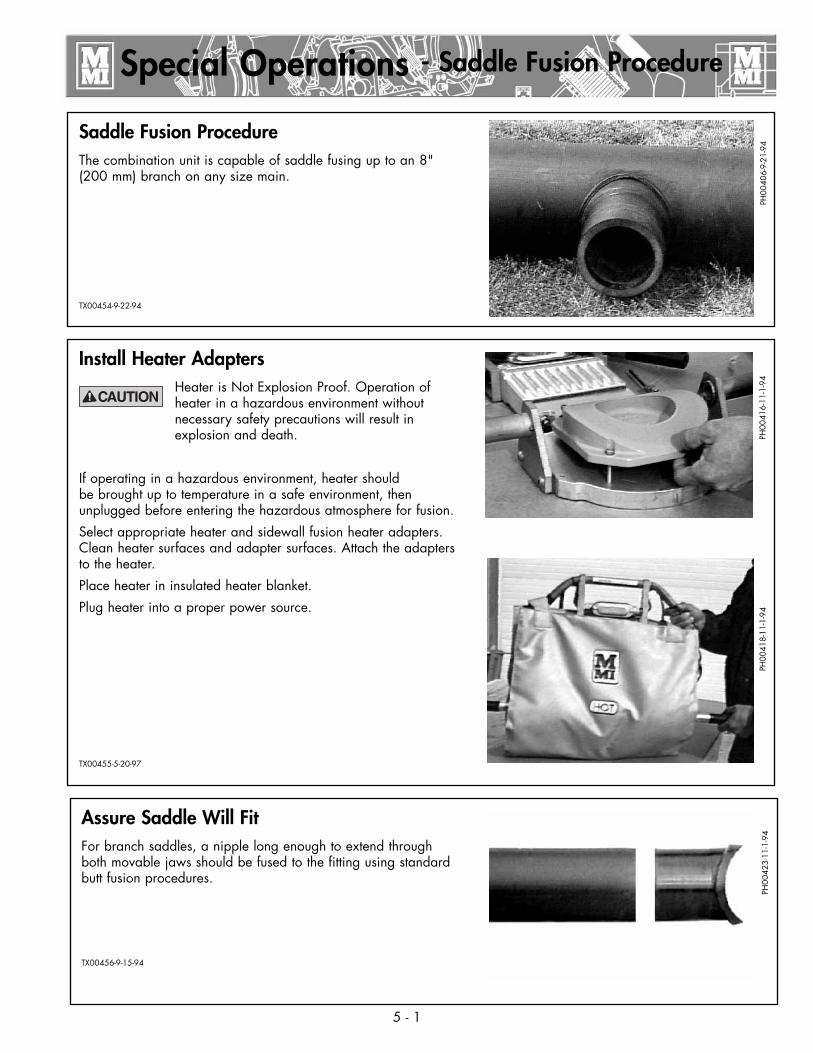
Install Heater AdaptersHeater is Not Explosion Proof. Operation of heater in a hazardous environment without necessary safety precautions will result in explosion and death.
If operating in a hazardous environment, heater should be brought up to temperature in a safe environment, then unplugged before entering the hazardous atmosphere for fusion.
Select appropriate heater and sidewall fusion heater adapters. Clean heater surfaces and adapter surfaces. Attach the adapters to the heater.
Place heater in insulated heater blanket.
Plug heater into a proper power source.
TX00455-5-20-97
Saddle Fusion ProcedureThe combination unit is capable of saddle fusing up to an 8" (200 mm) branch on any size main.
TX00454-9-22-94
Special Operations - Saddle Fusion Procedure
PH00
406-
9-21
-94
5 - 1
PH00
416-
11-1
-94
PH00
418-
11-1
-94
Assure Saddle Will FitFor branch saddles, a nipple long enough to extend through both movable jaws should be fused to the fitting using standard butt fusion procedures.
TX00456-9-15-94
PH00
423-
11-1
-94

Attach Carriage Assembly to MainPlace the machine on the main.
Place a line bolster on main opposite the carriage assembly if required.
Position the tailstock chains around the main and lock into the chain hooks.
Tighten the machine onto the main using the tailstock clamp knobs.
NOTICE: For main pipe sizes larger than 18”, it may be necessary to remove the carriage from the chassis.TX02137-07-11-03
Set Hydraulic PressureCheck hydraulic pressure. Shift the selector valve to the center position to set the pressure for heating (if heating pressure differs from fusion pressure). With the selector valve in the down position, the fusion pressure can be set.
Consult the pipe manufacturer for proper pressures.
TX00459-9-16-94
Install Clamping InsertsSelect and install appropriate clamping inserts in the movable jaw(s).
TX00457-9-16-94
Special Operations - Saddle Fusion Procedure
PH00
304-
9-23
-93
5 - 2
PH00
387-
9-21
-94
CD
0013
8B-9
-12-
94
Clean SurfacesUse 50 or 60 grit utility cloth to clean and rough the main to expose fresh material.
Rough the base of the fitting unless the manufacturer specifies otherwise.
TX00460-9-16-94
PH00
400-
9-21
-94
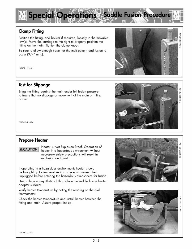
Test for SlippageBring the fitting against the main under full fusion pressure to insure that no slippage or movement of the main or fitting occurs.
TX00462-9-14-94
Prepare HeaterHeater is Not Explosion Proof. Operation of heater in a hazardous environment without necessary safety precautions will result in explosion and death.
If operating in a hazardous environment, heater should be brought up to temperature in a safe environment, then unplugged before entering the hazardous atmosphere for fusion.
Use a clean non-synthetic cloth to clean the saddle fusion heater adapter surfaces.
Verify heater temperature by noting the reading on the dial thermometer.
Check the heater temperature and install heater between the fitting and main. Assure proper line-up.
TX00463-9-16-94
Clamp FittingPosition the fitting, and bolster if required, loosely in the movable jaw(s). Move the carriage to the right to properly position the fitting on the main. Tighten the clamp knobs.
Be sure to allow enough travel for the melt pattern and fusion to occur (3/4" min.).
TX00461-9-15-94
Special Operations - Saddle Fusion Procedure
PH00
399-
9-21
-94
5 - 3
PH00
390-
9-21
-94
PH00
389-
9-21
-94
PH00
417-
11-1
-94
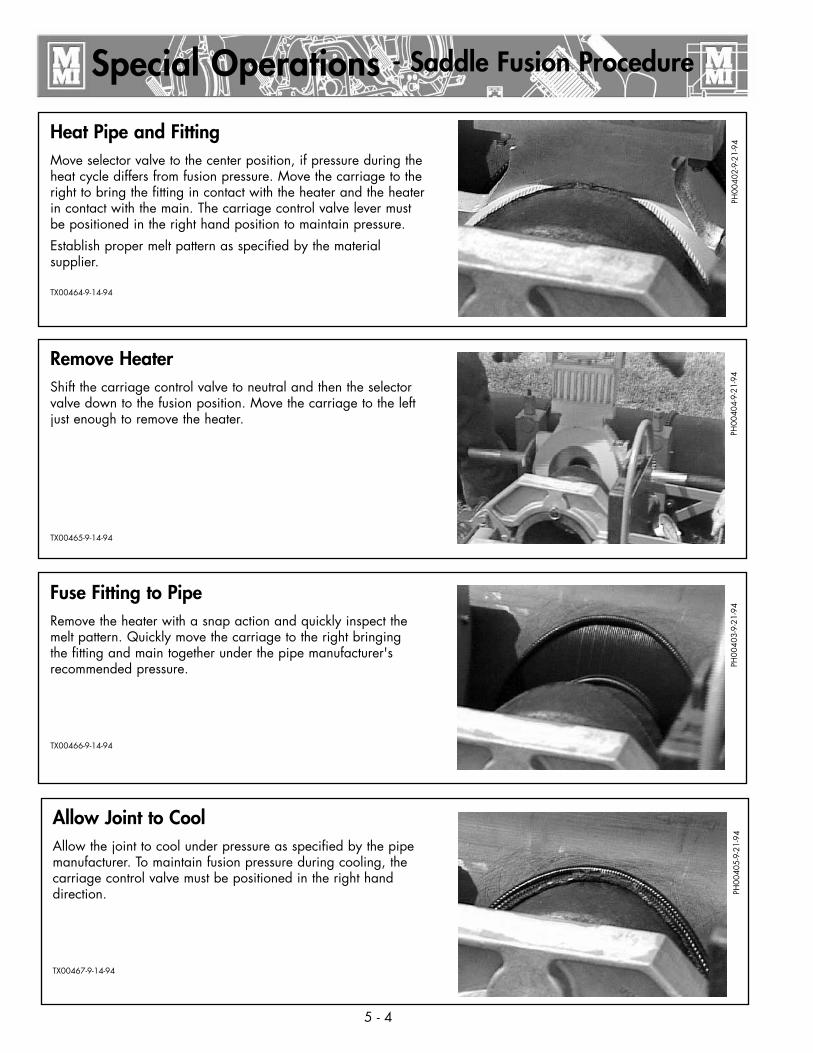
Remove HeaterShift the carriage control valve to neutral and then the selector valve down to the fusion position. Move the carriage to the left just enough to remove the heater.
TX00465-9-14-94
Fuse Fitting to PipeRemove the heater with a snap action and quickly inspect the melt pattern. Quickly move the carriage to the right bringing the fitting and main together under the pipe manufacturer's recommended pressure.
TX00466-9-14-94
Heat Pipe and FittingMove selector valve to the center position, if pressure during the heat cycle differs from fusion pressure. Move the carriage to the right to bring the fitting in contact with the heater and the heater in contact with the main. The carriage control valve lever must be positioned in the right hand position to maintain pressure.
Establish proper melt pattern as specified by the material supplier.
TX00464-9-14-94
Special Operations - Saddle Fusion Procedure
PH00
402-
9-21
-94
5 - 4
PH00
404-
9-21
-94
PH00
403-
9-21
-94
Allow Joint to CoolAllow the joint to cool under pressure as specified by the pipe manufacturer. To maintain fusion pressure during cooling, the carriage control valve must be positioned in the right hand direction.
TX00467-9-14-94
PH00
405-
9-21
-94
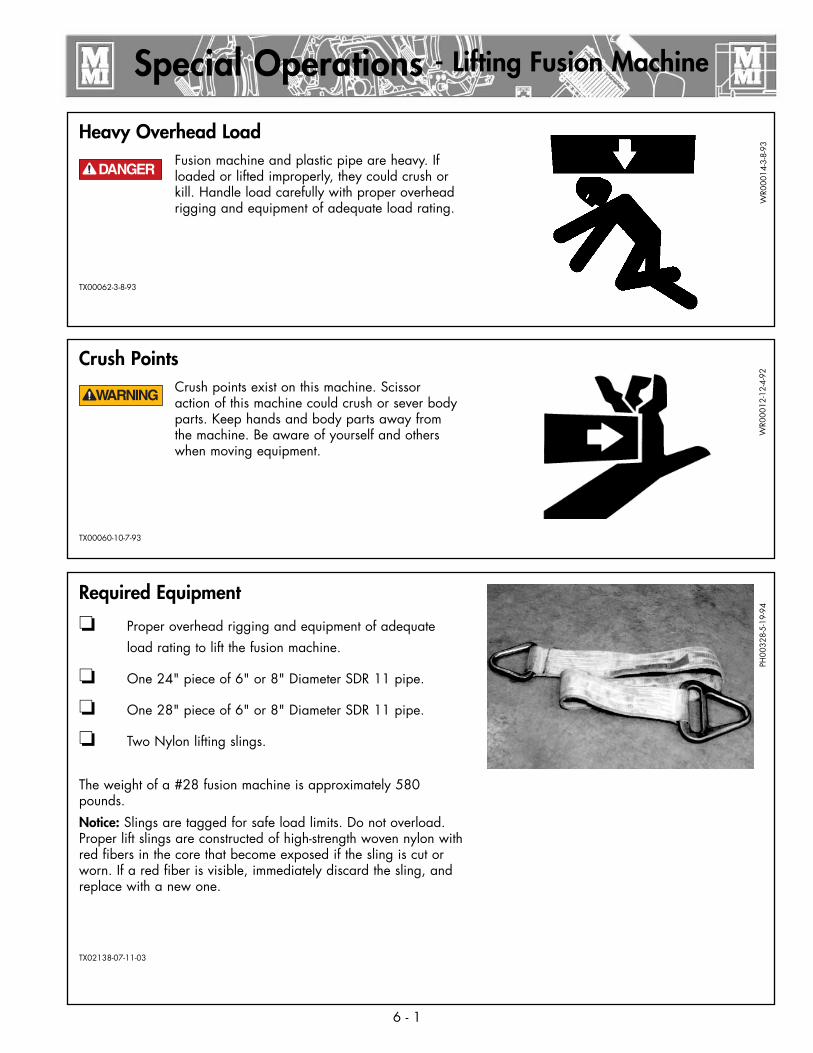
Crush PointsCrush points exist on this machine. Scissor action of this machine could crush or sever body parts. Keep hands and body parts away from the machine. Be aware of yourself and others when moving equipment.
TX00060-10-7-93
Required Equipment
❏ Proper overhead rigging and equipment of adequate load rating to lift the fusion machine.
❏ One 24" piece of 6" or 8" Diameter SDR 11 pipe.
❏ One 28" piece of 6" or 8" Diameter SDR 11 pipe.
❏ Two Nylon lifting slings.
The weight of a #28 fusion machine is approximately 580 pounds.
Notice: Slings are tagged for safe load limits. Do not overload. Proper lift slings are constructed of high-strength woven nylon with red fibers in the core that become exposed if the sling is cut or worn. If a red fiber is visible, immediately discard the sling, and replace with a new one.
TX02138-07-11-03
Heavy Overhead LoadFusion machine and plastic pipe are heavy. If loaded or lifted improperly, they could crush or kill. Handle load carefully with proper overhead rigging and equipment of adequate load rating.
TX00062-3-8-93
Special Operations - Lifting Fusion Machine
WR0
0014
-3-8
-93
6 - 1
WR0
0012
-12-
4-92
PH00
328-
5-19
-94
¡PELIGRO!

Ready the Unit for LiftingPivot the Facer into the facing position.
Bring the Jaws together so the pipe ends touch the facer.
Disconnect fusion unit from all power sources.
Insert the detent pins that secure the pipe lift and tow bar into their storage position.
TX00408-10-7-93
Attach SlingsLoop the lifting slings around the pieces of pipe.
Gather the sling ends together, and insert them into the hook that is attached to proper lifting equipment.
TX00409-09-16-94
Install Pipe PiecesWhen using 6" pipe install appropriate clamping inserts
Place the 24" long piece pipe into the movable jaws.
Place the 28" long piece pipe into the fixed jaws.
Securely tighten the clamp knobs so the jaws hold the pipe.
TX00407-9-16-94
Special Operations - Lifting Fusion Machine
PH02
497-
07-1
1-03
6 - 2
PH00
355-
9-12
-94
PH00
329-
5-19
-94
Lifting SafetyFollow all applicable federal, state, local, and industry specific regulations when lifting unit.
Never carry loads over people.
TX00410-10-12-93
SAFE
1ST-1
2-14
-92
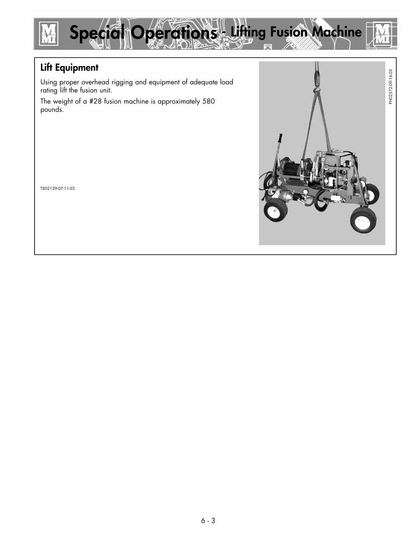
Lift EquipmentUsing proper overhead rigging and equipment of adequate load rating lift the fusion unit.
The weight of a #28 fusion machine is approximately 580 pounds.
TX02139-07-11-03
Special Operations - Lifting Fusion Machine
PH02
572-
09-1
6-03
6 - 3

Preventative MaintenanceTo insure optimum performance, the machine must be kept clean and well maintained.
With reasonable care, this machine will give years of service. Therefore, it is important that a regular schedule of preventive maintenance be kept.
Store machine inside, out of the weather, whenever possible.
TX00428-8-10-95
Change Hydraulic Fluid and FilterThe hydraulic fluid and filter should be replaced when the filter pressure gauge indicates “service filter” .
Fluid should also be changed as extreme weather conditions dictate.
Refer to the "Hydraulic Fluids" section of this manual for hydraulic oil recommendations.
TX02140-07-11-03
Maintenance
Washing the MachineThe machine should be cleaned, as needed with a soap and water wash.
TX00429-9-15-94
Check Hydraulic FluidThe hydraulic fluid level should be checked daily.
If hydraulic oil is not visible in the sight gauge, oil must be added.
Refer to the "Hydraulic Fluids" section of this manual for hydraulic oil recommendations.
TX00430-9-22-94C
D00
142-
11-2
-94
PH00
432-
11-1
-94
PH02
483-
07-1
1-03
PH02
604-
09-1
8-03
7 - 1
7 - 2
Maintenance
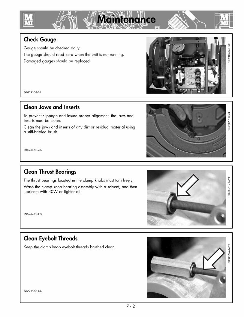
Clean Eyebolt ThreadsKeep the clamp knob eyebolt threads brushed clean.
TX00435-9-13-94
Clean Jaws and InsertsTo prevent slippage and insure proper alignment, the jaws and inserts must be clean.
Clean the jaws and inserts of any dirt or residual material using a stiff-bristled brush.
TX00433-9-15-94
Clean Thrust BearingsThe thrust bearings located in the clamp knobs must turn freely.
Wash the clamp knob bearing assembly with a solvent, and then lubricate with 30W or lighter oil.
TX00434-9-13-94
Check GaugeGauge should be checked daily.
The gauge should read zero when the unit is not running.
Damaged gauges should be replaced.
TX02291-3-8-04
PH02
489-
07-1
1-03
PH02
687-
7-30
-04
PH00
377-
9-14
-94
PH00
377-
9-14
-94
7 - 3
Maintenance
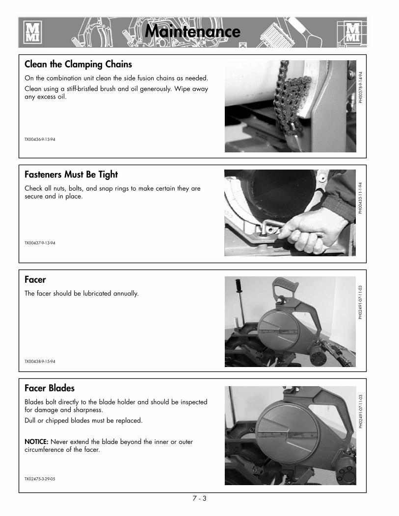
Facer BladesBlades bolt directly to the blade holder and should be inspected for damage and sharpness.
Dull or chipped blades must be replaced.
NOTICE: Never extend the blade beyond the inner or outer circumference of the facer.
TX02475-3-29-05
Fasteners Must Be TightCheck all nuts, bolts, and snap rings to make certain they are secure and in place.
TX00437-9-13-94
FacerThe facer should be lubricated annually.
TX00438-9-15-94
Clean the Clamping ChainsOn the combination unit clean the side fusion chains as needed.
Clean using a stiff-bristled brush and oil generously. Wipe away any excess oil.
TX00436-9-13-94
PH00
378-
9-14
-94
PH00
433-
11-1
-94
PH02
491-
07-1
1-03
PH02
491-
07-1
1-03

Maintenance
Clean Heater SurfacesThe heater faces must be kept clean and free of any plastic build up or contamination.
Before each fusion joint the heater surfaces must be wiped with a clean, non-synthetic cloth.
NOTICE: Do not use an abrasive pad or steel wool. Use a non-synthetic cloth that won't damage surfaces.
TX00440-8-14-08
PH02
317-
4-24
-02
Bleeding Air From Hydraulic SystemThe two carriage cylinders have air bleed screws and must be bled if the system ever runs low on oil or leaks air on inlet side of pump. Air in the system is indicated when carriage movement becomes jerky and erratic. To bleed the system, proceed as follows:
Remove upper jaws & clamping eye bolts from the two movable clamp jaws to expose the bleed plugs recessed in top of the lower jaws.
Tilt machine so the fixed jaw end is higher than the opposite end.
Shift the directional control and move the carriage to the fixed jaw end. Adjust the pressure to approximately 50-100 psi before proceeding.
Loosen the bleed plug on one cylinder next to the fixed jaw.
Hold pressure on the cylinder until no air is indicated and quickly tighten the plug.
Repeat this operation on the opposite cylinder.
Tilt the machine so the opposite end is higher than the fixed jaw end. Move the carriage to the end opposite the fixed jaw and repeat the above procedure on the this end of the cylinders.
TX00427-9-15-94
PH00
435-
11-1
-94
PH00
436-
11-1
-94
7 - 4
Maintenance
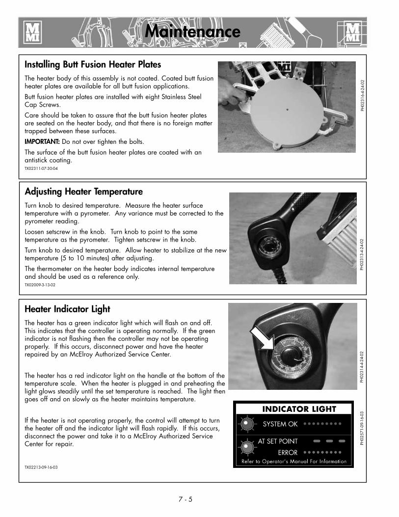
Installing Butt Fusion Heater PlatesThe heater body of this assembly is not coated. Coated butt fusion heater plates are available for all butt fusion applications.
Butt fusion heater plates are installed with eight Stainless Steel Cap Screws.
Care should be taken to assure that the butt fusion heater plates are seated on the heater body, and that there is no foreign matter trapped between these surfaces.
IMPORTANT: Do not over tighten the bolts.
The surface of the butt fusion heater plates are coated with an antistick coating.TX02311-07-30-04
Adjusting Heater TemperatureTurn knob to desired temperature. Measure the heater surface temperature with a pyrometer. Any variance must be corrected to the pyrometer reading.
Loosen setscrew in the knob. Turn knob to point to the same temperature as the pyrometer. Tighten setscrew in the knob.
Turn knob to desired temperature. Allow heater to stabilize at the new temperature (5 to 10 minutes) after adjusting.
The thermometer on the heater body indicates internal temperature and should be used as a reference only.TX02009-3-13-02
PH02
316-
4-24
-02
PH02
313-
4-24
-02
7 - 5
Heater Indicator LightThe heater has a green indicator light which will flash on and off. This indicates that the controller is operating normally. If the green indicator is not flashing then the controller may not be operating properly. If this occurs, disconnect power and have the heater repaired by an McElroy Authorized Service Center.
The heater has a red indicator light on the handle at the bottom of the temperature scale. When the heater is plugged in and preheating the light glows steadily until the set temperature is reached. The light then goes off and on slowly as the heater maintains temperature.
If the heater is not operating properly, the control will attempt to turn the heater off and the indicator light will flash rapidly. If this occurs, disconnect the power and take it to a McElroy Authorized Service Center for repair.
TX02213-09-16-03
PH02
314-
4-24
-02
PH02
571-
09-1
6-03
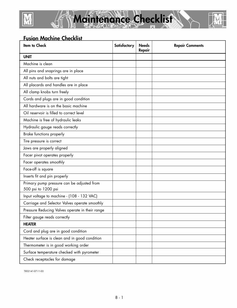
Fusion Machine ChecklistItem to Check Satisfactory Needs Repair Comments Repair
UNIT
Machine is clean
All pins and snaprings are in place
All nuts and bolts are tight
All placards and handles are in place
All clamp knobs turn freely
Cords and plugs are in good condition
All hardware is on the basic machine
Oil reservoir is filled to correct level
Machine is free of hydraulic leaks
Hydraulic gauge reads correctly
Brake functions properly
Tire pressure is correct
Jaws are properly aligned
Facer pivot operates properly
Facer operates smoothly
Face-off is square
Inserts fit and pin properly
Primary pump pressure can be adjusted from500 psi to 1200 psi
Input voltage to machine - (108 - 132 VAC)
Carriage and Selector Valves operate smoothly
Pressure Reducing Valves operate in their range
Filter gauge reads correctly
HEATER
Cord and plug are in good condition
Heater surface is clean and in good condition
Thermometer is in good working order
Surface temperature checked with pyrometer
Check receptacles for damage
Maintenance Checklist
8 - 1
TX02141-07-11-03
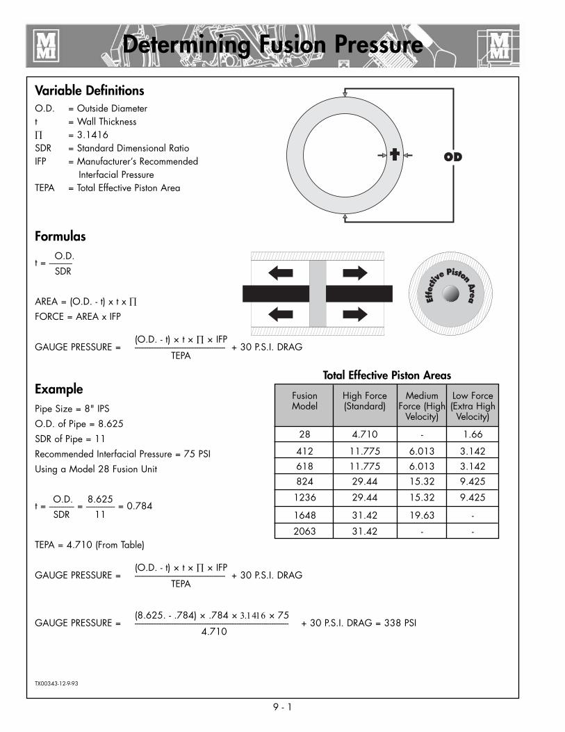
Variable DefinitionsO.D. = Outside Diametert = Wall Thickness∏ = 3.1416SDR = Standard Dimensional RatioIFP = Manufacturer’s Recommended Interfacial PressureTEPA = Total Effective Piston Area
Formulas O.D.t = ------------ SDR
AREA = (O.D. - t) x t x ∏
FORCE = AREA x IFP
(O.D. - t) × t × ∏ × IFPGAUGE PRESSURE = ----------------------------------------------- + 30 P.S.I. DRAG TEPA
ExamplePipe Size = 8" IPS
O.D. of Pipe = 8.625
SDR of Pipe = 11
Recommended Interfacial Pressure = 75 PSI
Using a Model 28 Fusion Unit
O.D. 8.625t = ------------- = --------------- = 0.784 SDR 11
TEPA = 4.710 (From Table)
(O.D. - t) × t × ∏ × IFPGAUGE PRESSURE = ----------------------------------------------- + 30 P.S.I. DRAG TEPA
(8.625. - .784) × .784 × 3.1416 × 75GAUGE PRESSURE = -------------------------------------------------------------------------------- + 30 P.S.I. DRAG = 338 PSI 4.710
TX00343-12-9-93
9 - 1
Determining Fusion Pressure
Fusion High Force Medium Low Force Model (Standard) Force (High (Extra High Velocity) Velocity)
28 4.710 - 1.66
412 11.775 6.013 3.142
618 11.775 6.013 3.142
824 29.44 15.32 9.425
1236 29.44 15.32 9.425
1648 31.42 19.63 -
2063 31.42 - -
Total Effective Piston Areas
10 - 1
Hydraulic Fluids
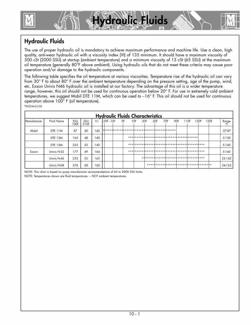
Hydraulic FluidsThe use of proper hydraulic oil is mandatory to achieve maximum performance and machine life. Use a clean, high quality, anti-wear hydraulic oil with a viscosity index (VI) of 135 minimum. It should have a maximum viscosity of 500 cSt (2000 SSU) at startup (ambient temperature) and a minimum viscosity of 13 cSt (65 SSU) at the maximum oil temperature (generally 80°F above ambient). Using hydraulic oils that do not meet these criteria may cause poor operation and/or damage to the hydraulic components.
The following table specifies the oil temperature at various viscosities. Temperature rise of the hydraulic oil can vary from 30° F to about 80° F over the ambient temperature depending on the pressure setting, age of the pump, wind, etc. Exxon Univis N46 hydraulic oil is installed at our factory. The advantage of this oil is a wider temperature range, however, this oil should not be used for continuous operation below 20° F. For use in extremely cold ambient temperatures, we suggest Mobil DTE 11M, which can be used to –16° F. This oil should not be used for continuous operation above 100° F (oil temperature).TX02244-2-2-04
NOTE: This chart is based on pump manufacturer recommendations of 65 to 2000 SSU limits.NOTE: Temperatures shown are fluid temperatures. – NOT ambient temperatures.
Hydraulic Fluids CharacteristicsManufacturer Fluid Name SSU SSU V.I. -20F -10F 0F 10F 30F 50F 70F 90F 110F 130F 150F Range 100F 210F °F
Mobil DTE 11M 87 40 145 ******************************************* -27-87
DTE 13M 165 48 140 ***************************************** 5-130
DTE 15M 225 53 140 ********************************************* 5-140
Exxon Univis N-32 177 49 164 ********************************************* 5-140
Univis N-46 233 55 163 ************************************* 25-142
Univis N-68 376 68 160 ************************************** 34-155
11 - 1
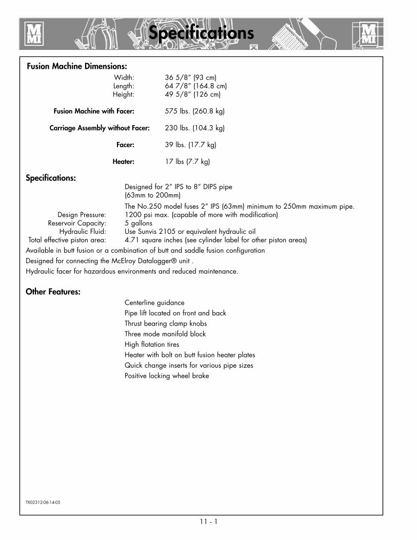
Fusion Machine Dimensions: Width: 36 5/8” (93 cm) Length: 64 7/8” (164.8 cm) Height: 49 5/8” (126 cm) Fusion Machine with Facer: 575 lbs. (260.8 kg)
Carriage Assembly without Facer: 230 lbs. (104.3 kg)
Facer: 39 lbs. (17.7 kg)
Heater: 17 lbs (7.7 kg)
Specifications: Designed for 2” IPS to 8” DIPS pipe (63mm to 200mm)
The No.250 model fuses 2” IPS (63mm) minimum to 250mm maximum pipe. Design Pressure: 1200 psi max. (capable of more with modification) Reservoir Capacity: 5 gallons Hydraulic Fluid: Use Sunvis 2105 or equivalent hydraulic oil Total effective piston area: 4.71 square inches (see cylinder label for other piston areas)Available in butt fusion or a combination of butt and saddle fusion configurationDesigned for connecting the McElroy Datalogger® unit .Hydraulic facer for hazardous environments and reduced maintenance.
Other Features: Centerline guidance Pipe lift located on front and back Thrust bearing clamp knobs Three mode manifold block High flotation tires Heater with bolt on butt fusion heater plates Quick change inserts for various pipe sizes Positive locking wheel brake
TX02312-06-14-05
Specifications
11 - 2
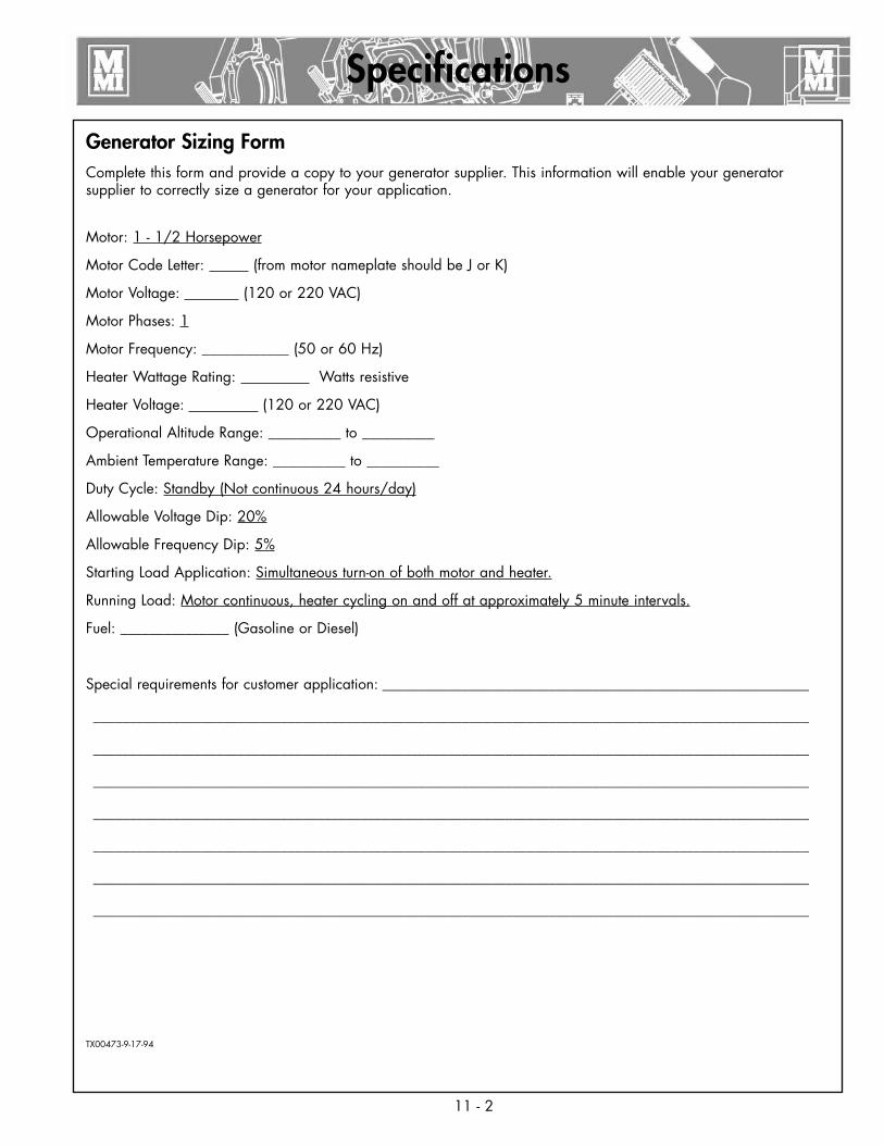
Generator Sizing FormComplete this form and provide a copy to your generator supplier. This information will enable your generator supplier to correctly size a generator for your application.
Motor: 1 - 1/2 Horsepower
Motor Code Letter: (from motor nameplate should be J or K)
Motor Voltage: (120 or 220 VAC)
Motor Phases: 1
Motor Frequency: ____________ (50 or 60 Hz)
Heater Wattage Rating: Watts resistive
Heater Voltage: (120 or 220 VAC)
Operational Altitude Range: __________ to __________
Ambient Temperature Range: __________ to __________
Duty Cycle: Standby (Not continuous 24 hours/day)
Allowable Voltage Dip: 20%
Allowable Frequency Dip: 5%
Starting Load Application: Simultaneous turn-on of both motor and heater.
Running Load: Motor continuous, heater cycling on and off at approximately 5 minute intervals.
Fuel: _______________ (Gasoline or Diesel)
Special requirements for customer application: ___________________________________________________________
___________________________________________________________________________________________________
___________________________________________________________________________________________________
___________________________________________________________________________________________________
___________________________________________________________________________________________________
___________________________________________________________________________________________________
___________________________________________________________________________________________________
___________________________________________________________________________________________________
TX00473-9-17-94
Specifications
About this manual . . .McElroy Manufacturing continually strives to give customers the best quality products available. This manual is printed with materials made for durable applications and harsh environments.
This manual is waterproof, tear resistant, grease resistant, abrasion resistant and the bonding quality of the printing ensures a readable, durable product.
The material does not contain any cellulose based materials and does not contribute to the harvesting of our forests, or ozone-depleting constituents. This manual can be safely disposed of in a landfill and will not leach into ground water.
TX001660-8-19-99


