- Service C GEORGIA COMPANY I NOVEMBER-DECEMBER 1962 THIS PUBLICATION IS FOR PLANNING AND INFORMATIONAL PURPOSES ONLY AND IS NOT TO BE CONSTRUED AS AUTHORITY FOR LAK~NG CHANGES ON AIRCRAFT OR EQUIPMENT, OR AS SUPERSEDING ANY ESTABLISHED OPERATIONAL OR MAINTENANCE PROCEDURES OR POLICIES. A Weighing The C-130
Transcript
-
Service C G E O R G I A C O M P A N Y
I
NOVEMBER-DECEMBER 1962
THIS PUBLICATION IS FOR PLANNING AND INFORMATIONAL PURPOSES ONLY AND IS NOT TO BE CONSTRUED AS AUTHORITY FOR LAK~NG CHANGES ON AIRCRAFT OR EQUIPMENT, OR AS SUPERSEDING ANY ESTABLISHED OPERATIONAL OR MAINTENANCE PROCEDURES OR POLICIES.
A
Weighing The C-130
The I
1 he weight and balance of an airplane is a major con- sideration throughout design and development into its various configurations. And, as you doubtless know, no matter how nearly alike they may be, no two air- planes will weigh the same.
Even though built to the same basic specifications, air- planes as big as the Hercules will vary in weight by quite a few pounds. Almost always, the first airplane in a series will weigh more than its successors built for identical missions. In the first place, the first airplane carries certain built-in provisions for special testing. And due to the constant alertness in engineering and production to weight penalties, progressive changes from airplane to airplane will normally result in weight reductions.
Once the basic airplane has the capabilit; of perform- ing its mission, any further sophistication or refine- ment is added at the expense of payload or range. That's why airplane designers fret over such small things as saving a few ounces in a handful of light- weight fasteners.
In addition to keeping the airplane as light as is prac- tical during design and to avoid piling on extra pounds during service, you must have an accurate record of weight and balance information if you are to be able to tell what performance you can expect of a particular airplane.
Weight and balance data are important not only to mission performance but to safety. And in cargo air- planes like the Hercules, the balance data-in terms 01 the center of gravity of the airplane-can be just as important to safety as the number of pounds taken aloft.
The actual weighing of the airplane at prescribed in- tervals is for the purpose of verifying the recorded - weight and balance data.
Weight and Balance Publications T. 0. 1-1B-50 and NAVWEPS 01-1B-50 is the basic technical manual for aircraft weight and balance. (This is one manual only, used by all military services and carrying the designations used within both Air Force and Navy systems.) This manual supports weight and balance controls programs by defining terms and illustrating the ways and means of maintain- ing accurate weight and balance records. It also gives details in handling items not part of the basic weight but impractical to unload prior to weighing the airplane.
Another technical manual, T. 0 . 1 - 1 B-40 or NAVWEPS 01-1B-40 is used with each individual Class 2 airplane. This is the Weight and Balance Data manual, used by the Air Force, Navy, Marines, and Coast Guard. For convenience, we will refer to it in the rest of this article as the IB-40.
The 1B-40 contains all the vital figures on a particular airplane and includes, as well, those forms necessary to maintain the weight and balarke records. The model
FINDING THE FUSELAGE (EXAMPLE)
517.08 WING JACK POINT--C-13OA ONLY 7
Class 2 Airplanes The C-130 is a Class 2 airplane as defined by the tech- nical orders. T. 0. 1-1B-52 establishes the requirements 1 for weighing of Class 2 airplanes. Generally speaking, o
airplanes covered by this T. 0. and class are cargo types which can readily be loaded so that the center of gravity falls outside the safe limits. Up-to-date weight and balance records must be maintained on all air- planes falling within this classification.
W
3
Each Class 2 airplane must be weighed at least once every two years, and each organization operating ARM OF 161 INCHES FOR
THE NOOE SHOCK STRUT
C-130's must weigh at least one of them each year. JACK POINT
These bi-annual weighings by no means stand alone * in determining the weight changes of the airplanes.
s z 7 . s e INCHES
Any significant change is recorded when it is made. 9,000 POUNDS TOTAL WEIGHT AT NOSE JACK 68,000
Lockheed Service News No. 37
and serial n u m ~ e r or the particular airplane to which each 1B-40 applies is imprinted on the cover and on the title page. Standard definitions and instructions covering the use of the forms are included in each
and accounting for items unavoidably weighed with, but not a part of, the basic airplane and for items which belong in the basic weight but were not in the airplane when it was weighed.
manual.
All forms and charts within the manual, other than Chart E, are standard, and they are all identified with the basic form number DD365. The different forms within the manual are identified, for convenience, by the letter that follows the form number.
Chart A (Form DD365A) is the Basic Weight Check List, initially filled in by Lockheed on each new Hercules. This is a list of fixed, but easily removed, operating equipment. I t also includes nonexpendable materials such as hydraulic fluid and trapped fuel.
Chart C is the Basic Weight and Balance Record, which is a continuous history of those changes in struc- ture and equipment that affect weight and balance. The initial entries into this chart are also made by Lockheed. This chart is primarily designed to keep the weight and balance records u p to date. The result- ing weight and moment on Chart B is posted to Chart C,. The last column in Chart C is a running total of the basic weight and location of the center of gravity in the basic airplane.
Chart E is a compilation of information (supplied by Lockheed) which is used in loading the ~ 1 3 0 as well as in maintaining balance while the airplane is in Columns are provided for checking off each item dur-
ing the inventory before each weighing of the air- flight. This section includes an airplane diagram,
plane.
Chart B is the Airplane Weighing Record. The initial Chart B for each Cr130 is completed by Lockheed at the time of manufacture, and this chart is used to com- plete entries in other charts. Chart B has spaces for the figures used in calculating the basic weight and
C center of gravity. On the back are columns for listing
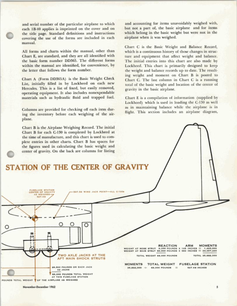
STATION OF THE CENTER OF GRAVITY
5D7.58 WING JACK POINT-ALL C-130.
REACTION ARM MOMENTS WEIGHT AT NOSE STRUT 9,000 POUNDS X 168 INCHES = 1,485,000 WEIGHT AT MAlN STRUT 59,000 POUNDS X 583 INCHES = 34,397,000 -
TWO AXLE JACKS AT THE TOTAL WEIGHT 68,000 POUNDS TOTAL 35,882,000
AFT MAlN SHOCK STRUTS
29,500 POUNDS ON EACH JACK XZ JACKS
89,000 POUNDS TOTAL WEIGHT AT THIS FUSELAGE STATION &- MOMENTS TOTAL WEIGHT FUSELAGE STATION
35,882,000 t 88,000 POUNDS = 527.68 INCHES
POUNDS TOTAL WEIGHT )OF THE AIRPLANE AS WEIGHED
November-December 1962
An adapter is screwed into the bottom of the cell to make it fit securely on the iack.
mum the amount of time that you actually keep the 0 airplane tied up. Among the approved weighing scales are the USAF Type C-1 (Cox and Stevens). Lockheed, and presumably most military installations, returns these scales to the manufacturer for calibration every six months. With this arrangement, the manufacturer guarantees the accuracy of the readings to be within 70 pounds in 70,000 pounds.
Most everything else you need is standard field level maintenance equipment. Choice permitted, you should elect to use axle jacks in preference to wing and fuse- lage jacks. Not only are axle jacks safer to use, both from the standpoint of personnel and equipment safety, but they involve less work.
dose to 70,000 pounds. Depending upon a few minor differences or changes, any one airplane could go over or under. If you are unsure, play it safe and use four wing jacks.)
There are some critical do's and do not's with regard' to weighing, especially concerning fuselage and wing jacks. These jacks, for use in weighing, must be in nea; perfect mechanical condition. Leaking valves or - seals are strictly prohibited, and never use a jack that is subject to sticking or binding. Also, the spring loaded casters (if the jacks have them) must be removed so that when the jacks are set in place all three feet are solidly planted on the floor before any load is applied.
With the ski-equipped C-130D and LGISOF, howevcr, you do not have this choice. Since the skis prohibit the use of axle jacks, these airplanes must be weighed on fuselage and wing jacks (or on flush or platform scales). The LC-l3OF can be weighed with four such tripod jacks, one at each of the two nose jack points
5 and one under each wing. The same is true of the s Gl3OD, provided the airplane weighs no more than r
70,000 pounds, Cl3OD's weighing more than 70,000 pounds, however, require two jacks under each wing
.) to prevent exceeding the structural limitations of wing jack pads. (The basiq weight of the C-130D is very
Fuselage nose jacks should be manifolded across the centerline of the airplane. And when it is necessary to use four wing jacks, each wing's pair of jacks must be manifolded fore and aft.
. . : f
$
Preparatiqn For the utmost in accuracy, the airplane has to be weighed stripped down as nearly to its basic weight as possible. It is equally important that all basic equip- ment be in place at the proper stations in the airplane. The airplane should also be cleaned, inside and out.
November-December 1962
Ground Handling, Servicing, and Airframe Maintenance: Jacking instructions are found in this handbook, along with related infdrma- tion necessary to weigh the airplane. The -2-2 published for the " B model applies to the "E" model as well.
Aircraft Electric Weighing Kit, Model ES-bA, Cox and Stevens: Operation and Service instruc- tions. Each of the three cells has a weighing capacity of 50,000 pounds. The total for the k i t i s 150,000 pounds.
Aircraf) Electronic Weighing Kit, Type D-I, Cox and Stevens: Operation and Service instruc- tions. Each of the four cells in this k i t has a weighing capaci* of 100,000 pounds. The total
Lockheed Service News No. 37
Balance Publications
I . V. 1-16-41)
HAVWEPS 01 -1 B - 4 ~
Weight and Balance Data: Each airplane has its own weight and balance data handbook which contains a complete history of the we mation plane. tains a tinuing
light for
This
SUPF the
nd rat ~ n d of
COI
balanc partic1
book a forms
.d .
:e i ular idso for
T. 0. 3582-2-4-1 1
Aircraft Electronic Weighing Kit,
Type D- I, Gilmore Industries: Operation and Service instructions. Each of the four cells in this k i t has a weight capacity of 100,000 pounds. The total for this k i t i s
-1 B-50 NAVWEPS 01 -1 B-50
r'uel tanks should be emptied, down to the trapped fuel which makes up a part of the basic weight and which is listed as part of the basic weight in Chart A. This requires defueling in the conventional manner through the single point refueling receptacle,. which removes all usable fuel by way of the airplane's boost pumps. External power will be required for this oper- ation. Following this, each tank must be individually drained down to its trapped fuel level through the condensate drain valves.
Hydraulic fluid is a part of the basic weight of the airplane, since it is not considered expendable. All hydraulic reservoirs should be serviced to the full level priorm to weighing. Also, all hydraulically actuated components should be in the normal position. That is, the ramp and cargo doors should be closed, and the b p s should be retracted. If by chance the airplane has been exposed to rain within the past few hours, operate aIl.flight controls to spill away any water that might have accumulated.
Preparatory to weighing on axle jacks, all shock struts should be deflated by loosening the upper hex nut * @ on the air valve about one-half turn, though not more than three-quarters of a turn. Exercise extreme cau- tion when doing this, and never back off the valve by releasing the bottom hex nut, or the valve may be blown out with explosive force. Install strut locks on the forward main struts before jacking the airplane.
In planning for the area in which to weigh the air- plane, there can be no compromises. The airplane must be in a completely enclosed building, with no drafts. The building's ventilation or air conditioning system must be turned off, and the room temperature should be allowed to stabilize before you jack the air- plane. Even small air currents in the room will rock the airplane sufficiently to induce some error into the weight indications. The airplane, jacks, and weighing equipment should "soak" at room temperature. When you set the weighing cells at zero prior to weighing, you are in effect calibrating them for the temperature at the moment. Changes in the temperature of the cells while the airplane is being weighed will alter the calibration and induce error into the reading.
The hangar floor upon which the airplane is weighed should be level. The airplane should be leveled before i t is jacked, and it should be kept level, within the limits of practicality, as it is raised.
If all struts are properly inflated, an empty (2-130 sit- ting on its gear will be in a slightly nose down atti- tude. The wings will be approximately level, but side to side leveling is not as critical as fore and aft level- ing. If you are going to weigh the airplane with wing and fuselage jacks, level the airplane on its gear by inflating (or deflating) the nose gear strut while an observer monitors a plumb bob over the built-in level-
Lockheed Service News No. 37
ing plate on the lert noor curb at fuselage station 647. If you are using axle jacks, deflate each strut. Insrail Make sure the plumb line hangs straight down from strut locks on the forward main gear struts. the attach angle near the top of the cargo compart. @ ment-that is, the string should not contact any insula- tion or equipment that will offset it. (The airplane can be leveled more precisely with a transit than with the plumb bob. For instructions on this method of level- ing, refer to T. 0. 1G130-3.)
Place the jack going under the nose gear into position first. Raise this jack to level the airplane before mov- ing the main gear jacks into position. (With the struts completely deflated, a C-130 sitting on a level floor will be approximately four inches nose low.)
Weighing Operations
Compared to the time required to get ready, relatively little time is required to weigh the airplane. Careful weighing should take about forty-five minutes, pro- vided adequate preparations have been made.
Using everything that has been said before as back- ground, let's go through the whole process in a sort of timetable arrangement.
Ideally, you should secure the hangar at least a day in advance of weighing. Move all equipment-jacks, weighing kits, and miscellaneous support equipment- into the hangar this first day. If it is possible to take the airplane out of service a day in advance, it would be advantageous to move i t into the hangar on the first day also.
An hour before you are ready to raise the airplane on jacks, turn on the electronic weighing equipment and let it warm up. After the weighing equipment has
A view of the leveling plate and plumb bob in use on a KC-130F.
1 warmed up, adjust each individual weighing cell to zero. Install the adapters to the weighing cells and I these to the jacks. Move the jacks into place before positioning cells on them.
The jacking procedure must be directed through an
0 intercommunications system by a man stationed at the The men stationed at the iackr must be in contact with +he leveling plate in the airplane. man inside the airplane.
November-December 1962
MAIN GEAR STRUT LOCK
PIN THROUGH UPPER ATTACHMENT '\I - PIN FOR LOWER LUG
I A
If you are using wing and fuselage jacks, inflate the nose gear strut to level the airplane. If necessary to level the wings, this can be accomplished by inflating or deflating the two struts on a side.
Very slowly and very carefully under the direction of the man stationed at the leveling plate raise the air- plane until all wheels clear the floor. Keep the air- plane as level as is practical while it is raised.
After satisfactory leveling has been accomplished, the man at the leveling plate should leave the airplane. Then the weight applied to each cell should be read and recorded.
Still keeping the airplane level, lower it until all weight has been taken off the cells. Again read and record the weight indications of each cell. They should be very nearly zero.
If any cell reads slightly (up to 25 pounds) above zero, divide the reading by two and subtract this from the weight recorded for that cell. If any cell reads slightly below zero, add the total minus reading to the weight recorded for that cell.
Again zero the cells and rotate them among the jacks, then re-weigh the airplane exactly as before. For the weighing to be considered satisfactory, the total weight of the airplane as determined the first time must be within one-tenth of one percent of the total weight as determined the second time around. That is to say, the two weighings should be within 70 pounds of each other for a 70,000 pound airplane.
Several things could possibly cause an unsatisfactory weighing. If you can account for a procedural error or mechanical difficulty that might have resulted in an ,unsatisfactory indication during one weighing, weigh the airplane a third time to try to get two weighings within 70 pounds of each other. Be sure to again recali- brate and shift the cells before the third weighing.
Unsatisfactory weighings can result from misalignment of jack, cell, and jack pad, from variations in electric power, from appreciable temperature changes, from air currents within the hangar, or from faulty weigh- ing equipment. Check on the possibility of each of these troubles.if you are unable to obtain satisfactory results after three weighings.
Once your weighing is satisfactory, enter the scale read- ings in the column provided on Chart B. Enter and subtract the weights of strut locks and other tare to get the net weights which are to go in the column pro- vided. The arms "E" for the midsection cells and "F" for the nose section cells are given in your Chart E section of the 1B-40. They are in the weighing instruc- tions and on the airplane diagram, so there is no need for you to do the measuring outlined at the bottom front of Form B.
Multiply the weights times arms to get the moments, then total them in the column provided. Transfer these totals to the back of the form and complete the form according to the instructions provided on it and in the text of the 1B-40 technical order.
Flush or Platform Scales We've said very little about the use of flush or plat- form scales, since few facilities have this type of equip
Lockheed Service News No. 37
ment with sufficient capacity to weigh the Hercules. 11
this type of equipment is available to you, however, use it, for this is certainly the easiest of the alternative methods for weighing the airplane.
Tow the airplane onto the scales, then prepare it for weighing as follows.
First, you must get the weight concentrated on three points, the nose gear and the two aft main gear wheels. T o do this, deflate the forward main gear struts. Put an axle jack under each of these two struts (one at the time) and raise the jacks until the struts are fully compressed. Then lock each strut in this position with main gear strut locks. The top of the strut lock fits in a horizontal slot in the strut mounting flange. Fasten the lower part of the strut lock with a pin through the hole in the lower lug just inboard of the brakes. After each forward strut is secured, release and remove the axle jack. Next level the airplane by inflating or deflating the nose gear strut.
Then read the weight of the airplane as when weigh- ing on axle jacks. The moment arms are practically the same for platform scale weighing as for axle jack weighing, as ;he weight in both- cases is concentrated A typical indicating unit of an electronic weighing kit. downward from the center of the gear struts. See the Actual weight in pounds is read from indications you seled chart below. Be sure to subtract the tare (weight of with the knobs shown. The meter at the top will center when
0 jacks and other equipment used on the scales* hut not your initial load selection and weight adjushent are cor- part of the basic airplane equipment) . rect for the cell selected.
November-December 1962
SUPPL DIVISION DIVISION
IM R. WElLAND
CUSTOMER SERVICE )PERATIONS DEPT MGR
. WALKER MER TRAINING MGR
JIM W. TROUP AEROSPACE
2 DEPT MGR
A. HURLBURT SUPPLY MGR
JACK C. GARWOOD I PRANK W. DENNINGTON FIELD SERVICE SPARES STORES DEPT MGR DEPT MGR
REPRESENTATIVES ON FIELD ASSIGNMENT
AIR WEATHER SERVICE, McCLELLAN A F B, CALIF.
T. G. "TOM" McLAIN WA-2-1511 Ext. 20211
CHARLESTON AIR FORCE BASE, SOUTH CAROLINA
B. I. "BEN" HALL III* PH. SH 7-4111
F. A. "Fred" Hehmeyer Ext. 3422
CHATEAUROUX AIR BASE, FRANCE
u. s. GO^^ GOL~GHTLY PH. 2051
- - - - - - -
DYESS AIR FORCE BASE,-TEXAS T. E. "EARL" HUDDLESTON pH. OW 2-1212
J. M. "Joe" P r i e s t Ext. 8479
EGLlN AIR FORCE BASE, FLORIDA
G. E. "GEORGE" CONLEY PH. 67-3597
J. J. "Joe" 3haffer
EVREUX-FAUVILLE AIR BASE, FRANCE
J. H. "JIM" G O m E N * PH. 1194 o r 1195 A. H. "Arch" McCleskey
W. E. "Bill" Hastings
HALlM NR' BASE, DJAKARTA, INDONESIA J. P. %JJ.Mt' CURRENT* PH. Halim 229
H. t'Hal" Clary J. A. "Jack" Davidson H. E. "Gene" Gibson J. T. "Jim fl Murone C. E. tlCharley" Shuler F. J. "Ox" Ochsenfeld E. "Ed" O'Rourke
s h i m hrse, are we11 known ammg Mi* men. T o extend the airplane's capitWt$m a~ aa assault-type 5 transport, the STOLMod (%at Tkk-Qff and Land- %% '>
ing Modifications) C-180 shchm rm &k hssue's cove incorporates a drag chute, p a t w &p deflection faster flap operation, increased aitemn and tu chords, and other changes. With these modifications,
Lockheed Surv'ka Newa No. 37
HICKAM AIR FORCE BASE, HAWAII NATC, PATUXENT RIVER, MARYLA
pH. 4-4111 EX^. 414-292
N. L. "Normw Steckler F. E. "FRANK" HOWELL
RCAF, NAMAO, ALBERTA, CANADA
M. "STEVE" STEVENS PHs SW 9-3145
pH. L14-2093 H. H. "HOYT" VAUGHN
H. GL 9-2561
NALF, EL CENTRO, CALIFORNIA TACHIKAWA AIR BASE, JAPAN
R. "ROGER" COLEY L. C. "TUSKY" MORGAN* PH. 2-8993 F. W. "Franku Griffith
C. E. "CLIFF" ROOKER S. A. "Sid" Manning C. E. "CHUCK" COXWELL PH. HE 5-3411 C. E. "Charlie" Landrum W. J. "Billt7 Walls Ext. 7129
H. E. "RED" PACKARD * PH. Wickford CY 4-4511 pH. 7-8792 J. W. "Jackv Marhn E. C. "Padge" Padgett J. A. "Jacktt Roelofs M. L. "Marty" Turner
the STOLMod G130 lands and takes off in about 14 times its length.
Another cop (2-130 STOL performer is the NC130B, which incorporates boundary layer control to provide the ability to land and take off in five times the air-
ent and potentially-extended, short- and rough-field operating capabilities are particularly im- portant to the G130 as a combat transport. As the first-line airlifter for the U.S. Strike Command, the ClSO muet at all times be in readiness to deploy rapidly to almost any place on the globe in the event of a breach of or threat to world peace.