37
Node Power Supply Enclosure Installation Manual Effective: November 2018

Node Power Supply EnclosureInstallation Manual
Effective: November 2018
2 031-295-B0-001, Rev. B (11/2018)
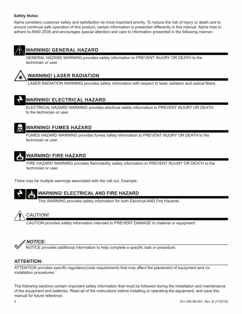
Safety NotesAlpha considers customer safety and satisfaction its most important priority. To reduce the risk of injury or death and to ensure continual safe operation of this product, certain information is presented differently in this manual. Alpha tries to adhere to ANSI Z535 and encourages special attention and care to information presented in the following manner:
The following sections contain important safety information that must be followed during the installation and maintenance of the equipment and batteries. Read all of the instructions before installing or operating the equipment, and save this manual for future reference.
There may be multiple warnings associated with the call out. Example:
ATTENTION provides specific regulatory/code requirements that may affect the placement of equipment and /or installation procedures.
ATTENTION:
NOTICE provides additional information to help complete a specific task or procedure. NOTICE:
ELECTRICAL HAZARD WARNING provides electrical safety information to PREVENT INJURY OR DEATH to the technician or user.
WARNING! ELECTRICAL HAZARD
FUMES HAZARD WARNING provides fumes safety information to PREVENT INJURY OR DEATH to the technician or user.
WARNING! FUMES HAZARD
FIRE HAZARD WARNING provides flammability safety information to PREVENT INJURY OR DEATH to the technician or user.
WARNING! FIRE HAZARD
This WARNING provides safety information for both Electrical AND Fire Hazards.
WARNING! ELECTRICAL AND FIRE HAZARD
CAUTION provides safety information intended to PREVENT DAMAGE to material or equipment.
CAUTION!
GENERAL HAZARD WARNING provides safety information to PREVENT INJURY OR DEATH to the technician or user.
WARNING! GENERAL HAZARD
LASER RADIATION WARNING provides safety information with respect to laser radiation and optical fibers.
WARNING! LASER RADIATION

3031-295-B0-001, Rev. B (11/2018)
Node Power Supply EnclosureInstallation Manual031-295-B0-001, Rev. BEffective November 2018 Alpha Technologies, Inc.
DisclaimerImages contained in this manual are for illustrative purposes only. These images may not match your installation.Operator is cautioned to review the drawings and illustrations contained in this manual before proceeding. If there are questions regarding the safe operation of this powering system, please contact Alpha Technologies or your nearest Alpha representative.Alpha shall not be held liable for any damage or injury involving its enclosures, power supplies, generators, batteries or other hardware if used or operated in any manner or subject to any condition not consistent with its intended purpose or is installed or operated in an unapproved manner or improperly maintained.
Contact InformationSales information and customer service in USA (7AM to 5PM, Pacific Time) .............................................1 800 322 5742Complete technical support in USA (7AM to 5PM, Pacific Time or 24/7 emergency support) ....................1 800 863 3364Sales information and technical support in Canada ....................................................................................1 888 462 7487Website ........................................................................................................................................................www.alpha.com
IntroductionThis manual describes the Node Power Supply Enclosure (NPS) and relevant installation information and is intended for the installers of the enclosure. The installers must be familiar with enclosure installation as well as system grounding and the safety issues related to lasers and fiber optic cabling.
AudienceThis guide is intended for experienced installers familiar with the mechanical and electrical requirements of fiber optic systems and qualified, licensed installation personnel. Review the support documentation on the website to become familiar with the features and functions of the equipment in this system before proceeding. Failure to install and/or use this equipment as instructed in the system documents can result in damage to the equipment. This system is only serviceable by qualified personnel.
Trademark InformationAlpha® is a registered trademark of Alpha Technologies.
Revision History - P/N 031-295-B0-001Version Date Description of Changes and New Features
A 04 / 2009 Initial Release of Document
B 11/2018
The document format has been updated to match current style.Specification and battery runtime tables have been amended.References (text, graphics) to XM2 Power Supplies have been replaced with XM3.Updated cooling fan connectivity illustration.Added part number for right angle power cord at various locations throughout the manual.Updated battery termination illustrations.

4 031-295-B0-001, Rev. B (11/2018)
ContentsImportant Safety Instructions ...................................................................................... 6
Battery Maintenance Guidelines ................................................................................................................... 6Electrical Safety ............................................................................................................................................ 6Mechanical Safety ......................................................................................................................................... 7Recycling and Disposal Instructions ............................................................................................................. 7Battery Safety Notes ..................................................................................................................................... 7Chemical Hazards ......................................................................................................................................... 7
Grounding and Earth Connection Notes .................................................................... 8Safety Ground and Earth Connection ........................................................................................................... 8
1.0 Overview.................................................................................................................. 91.1 Node Power Supply (NPS) Enclosures ................................................................................................... 91.2 Specifications ........................................................................................................................................ 101.3 Battery Runtime .................................................................................................................................... 111.4 Parts List ............................................................................................................................................... 13
2.0 Installation............................................................................................................. 142.1 Pole-mounted Configuration ................................................................................................................. 14
2.1.1 Installation on Wooden Pole .......................................................................................................... 152.1.2 Installation on Steel/Concrete Pole................................................................................................ 17
2.2 Rack-mounted Configuration ................................................................................................................ 192.2.1 Installation Procedure .................................................................................................................... 20
2.3 Wall-mounted Configuration .................................................................................................................. 212.3.1 Installation ...................................................................................................................................... 22
2.4 Floor-mounted Configuration ................................................................................................................ 232.4.1 Installation ...................................................................................................................................... 24
2.5 Connecting the Utility Power ................................................................................................................. 242.5.1 Service Power ................................................................................................................................ 25
2.6 Connecting the Coaxial Cable ............................................................................................................... 272.6.1 Coaxial Cable Surge Protector Installation Instructions................................................................. 272.6.2 Connecting the Service Power Inserter (SPI) ................................................................................ 282.6.3 Connecting the Service Power Inserter-RF (SPI-RF) .................................................................... 29
2.7 Battery Installation ................................................................................................................................. 302.7.1 Battery Installation Procedure........................................................................................................ 312.7.2 Battery Wiring Diagram .................................................................................................................. 322.7.3 Battery Terminal Connections ........................................................................................................ 33
2.8 Installing the XM3 Power Supply ......................................................................................................... 342.9 Cooling Fan Kit Installation .................................................................................................................. 352.10 Cooling Fan Kit Removal .................................................................................................................... 35
3.0 Populating the Cabinet and Turn-up Checklist .................................................. 36
5031-295-B0-001, Rev. B (11/2018)
Figures and TablesFig. 1-1 Node Power Supply Enclosures, pole-mount, rack-mount, and wall-mount configurations ................................9Fig. 2-1 Dimensions and Features .................................................................................................................................14Fig. 2-2 Wooden Pole Installation ..................................................................................................................................16Fig. 2-3 Steel/Concrete Pole Installation ........................................................................................................................18Fig. 2-4 Dimensions, Rack-mounted NPS Enclosure ....................................................................................................19Fig. 2-5 Dimensions, Wall-mounted NPS Enclosure ......................................................................................................21Fig. 2-6 Dimensions, Floor-mounted NPS Enclosure ....................................................................................................23Fig. 2-7 120Vac Service Entrance Wiring .......................................................................................................................25Fig. 2-8 520-R Receptacle Wiring ..................................................................................................................................26Fig. 2-9 Surge Protector mounting locations ..................................................................................................................27Fig. 2-10 Mounting locations for the standard SPI ...........................................................................................................28Fig. 2-11 Cover Removal .................................................................................................................................................28Fig. 2-12 Coaxial Cable Connection ................................................................................................................................28Fig. 2-13 Mounting locations for the SPI-RF ....................................................................................................................29Fig. 2-14 Battery Identification Label ................................................................................................................................30Fig. 2-15 NPS Battery Wiring Diagram with 100GXL battery string .................................................................................32Fig. 2-16 Hardware stack-up, Threaded Battery insert ....................................................................................................33Fig. 2-17 Hardware stack-up, Threaded Battery insert with optional in-line fuse .............................................................33Fig. 2-18 XM Series 3 Power Supply ...............................................................................................................................34Fig. 2-19 Cooling fan installation configuration ................................................................................................................35
Table 1-1 Enclosure Specifications ...................................................................................................................................10Table 1-2 XM2-300HP Battery Runtime ............................................................................................................................ 11Table 1-3 XM3-910HP 36V Battery Runtime (Configured for 90V Output) .......................................................................12Table 1-4 XM3-615HP 36V Battery Runtime (Configured for 60V Output) .......................................................................12Table 1-5 Parts List ...........................................................................................................................................................13Table 2-1 Service Entrance Circuit Breaker Requirements ..............................................................................................24

6 031-295-B0-001, Rev. B (11/2018)
Important Safety InstructionsReview the drawings and illustrations contained in this manual before proceeding. If there are any questions regarding the safe installation or operation of the system, contact Alpha Technologies or the nearest Alpha representative. Save this document for future reference.
To reduce the risk of injury or death, and to ensure the continued safe operation of this product, notifications have been placed throughout this manual. Where these notifications appear, use extra care and attention.
Alpha Technologies’ products are subject to change through continual improvement processes. Therefore, specifications or design layouts may vary slightly from the descriptions included in this manual. Updates to the manual are issued when changes affect form, fit or function.
ATTENTION:
Battery Maintenance GuidelinesThe battery maintenance instructions listed below are for reference only. Battery manufacturer’s instructions for transportation, installation, storage or maintenance take precedence over these instructions.
• To prevent damage, inspect batteries every 3 months for:Signs of battery cracking, leaking or swelling. The battery should be replaced immediately by authorized personnel using a battery of the identical type and rating.Signs of battery cable damage. Battery cable should be replaced immediately by Authorized Personnel using replacement parts specified by vendor.Loose battery connection hardware. Refer to battery manufacturer’s documentation for the correct torque and connection hardware for the application.
• Apply battery manufacturer’s specified antioxidant compound on all exposed connections.• Verify battery terminals and/or exposed connection hardware is not within 2 inches of a conductive surface.
Reposition batteries as necessary to maintain adequate clearance.• Clean up any electrolyte (battery emission) in accordance with all federal, state, and local regulations or codes.• Proper venting of the enclosure is recommended. Follow the Battery Manufacturer’s approved transportation and
storage instructions.• Always replace batteries with those of an identical type and rating. Never install old or untested batteries.• Do not charge batteries in a sealed container. Each individual battery should have at least 0.5 inches of space
between it and all surrounding surfaces to allow for convection cooling.• All battery compartments must have adequate ventilation to prevent an accumulation of potentially dangerous gas.
Electrical Safety• Lethal voltages are present within the power supply and electrical boxes. Never assume that an electrical
connection or conductor is not energized. Check the circuit with a volt meter with respect to the grounded portion of the enclosure (both AC and DC) prior to any installation or removal procedure.
• Always use the buddy system when working under hazardous conditions.• A licensed electrician is required to install permanently wired equipment.• Input voltages can range up to 240 VAC. Ensure that utility power is disabled before beginning installation or
removal.• Ensure no liquids or wet clothes contact internal components.• Hazardous electrically live parts inside this unit are energized from batteries even when the AC input power is
disconnected.

7031-295-B0-001, Rev. B (11/2018)
Battery Safety Notes
Lead-acid batteries contain dangerous voltages, currents and corrosive material. Battery installation, maintenance, service and replacement must be performed only by authorized personnel.
WARNING! GENERAL HAZARD
Chemical HazardsAny gelled or liquid emissions from a valve-regulated lead-acid (VRLA) battery contain dilute sulfuric acid, which is harmful to the skin and eyes. Emissions are electrolytic, and are electrically conductive and corrosive.
To avoid injury:• Servicing and connection of batteries shall be performed by, or under the direct supervision of, personnel
knowledgeable of batteries and the required safety precautions.• Always wear eye protection, rubber gloves, and a protective vest when working near batteries. Remove all metallic
objects from hands and neck.• Batteries produce explosive gases. Keep all open flames and sparks away from batteries.• Use tools with insulated handles, do not rest any tools on top of batteries.• Batteries contain or emit chemicals known to the State of California to cause cancer and birth defects or other
reproductive harm. Battery post terminals and related accessories contain lead and lead compounds. Wash hands after handling (California Proposition 65).
• Wear protective clothing (insulated gloves, eye protection, etc.) whenever installing, maintaining, servicing, or replacing batteries.
• If any battery emission contacts the skin, wash immediately and thoroughly with water. Follow your company’s approved chemical exposure procedures.
• Neutralize any spilled battery emission with the special solution contained in an approved spill kit or with a solution of one pound Bicarbonate of soda to one gallon of water. Report chemical spill using your company’s spill reporting structure and seek medical attention if necessary.
• All battery compartments must have adequate ventilation to prevent an accumulation of potentially dangerous gas.• Prior to handling the batteries, touch a grounded metal object to dissipate any static charge that may have
developed on your body.• Never use uninsulated tools or other conductive materials when installing, maintaining, servicing or replacing
batteries.• Use special caution when connecting or adjusting battery cabling. An improperly connected battery cable or an
unconnected battery cable can make contact with an unintended surface that can result in arcing, fire, or possible explosion.
Mechanical Safety• Keep hands and tools clear of fans. Fans are thermostatically controlled and will turn on automatically.• Power supplies can reach extreme temperatures under load.• Use caution around sheet metal components and sharp edges.
Recycling and Disposal InstructionsSpent or damaged batteries are considered environmentally unsafe. Always recycle used batteries or dispose of the batteries in accordance with all federal, state and local regulations.
8 031-295-B0-001, Rev. B (11/2018)
Grounding and Earth Connection Notes
1
2 3
4
2' min.
Connection made with Burndy connector (P/N YG HR58 C2W-3
or equivalent)
Terminate at enclosure or external Burndy ground
Terminate at service entrance ground
#6AWG
Two 8' (2.4m) ground rods, 6' (1.8m) apart, min.
(may require additional ground rods to meet NEC minimum grounding standard of 25 ohms or less)
Connection made with Burndy connector (P/N YGHP58C2W-2TN or equivalent)
#2AWG
Service Grounding (required)
• #6 bare copper wire from Service Neutral / Ground Bar with 2 ground rods located 6’ (1.8m) apart. If system ground resistance is greater than 25 ohms consult with local code authority for a suitable grounding system.
Lightning Protection (optional)
• 1/2” x 8’ (13mm x 2.4m) copper ground rod, four places, driven about 2’ (0.6m) (typical) from the corners of the pad.
• #6 bare copper wire loop terminated to each ground rod and buried below grade 30” (.762m) (min). Corrosion-proof connections (25+ year life-span), and hardware suitable for direct burial MUST be used.
• #6 bare copper wire from loop to the enclosure.
1
2
3
4
• Alpha Technologies recommends using the grounding method illustrated below. The grounding method for a particular site will be dependant upon soil type, available space, local codes, NESC (National Electric Safety Code), NEC (National Electric Code), and other site-specific characteristics.
• Alpha recommends less than 25 ohm ground resistance in the grounding system in accordance with NESC Section 9 and NEC Article 250, 820 Part IV.
• Alpha recommends that if there are other electrical services in the area of any part of the enclosure or grounding system shown below that you contact your local code authority on possible 20’ (6.0m) bonding conductor requirements for connecting the different grounding systems.
• Alpha Technologies assumes no responsibility or liability for failure of the installer to comply with the requirements of applicable local and national codes. Where allowed, exothermic welding may be used as an alternative to Burndy clamps and connectors.
NOTICE:
Enclosure Footprint
9031-295-B0-001, Rev. B (11/2018)
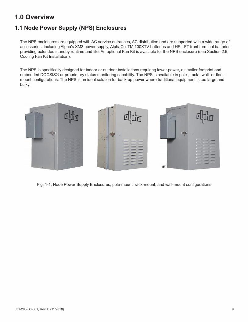
1.0 Overview1.1 Node Power Supply (NPS) Enclosures
The NPS enclosures are equipped with AC service entrances, AC distribution and are supported with a wide range of accessories, including Alpha’s XM3 power supply, AlphaCellTM 100XTV batteries and HPL-FT front terminal batteries providing extended standby runtime and life. An optional Fan Kit is available for the NPS enclosure (see Section 2.9, Cooling Fan Kit Installation).
The NPS is specifically designed for indoor or outdoor installations requiring lower power, a smaller footprint and embedded DOCSIS® or proprietary status monitoring capability. The NPS is available in pole-, rack-, wall- or floor-mount configurations. The NPS is an ideal solution for back-up power where traditional equipment is too large and bulky.
Fig. 1-1, Node Power Supply Enclosures, pole-mount, rack-mount, and wall-mount configurations

10 031-295-B0-001, Rev. B (11/2018)
1.0 Overview, continued
1.2 Specifications
Table 1-1, Enclosure Specifications
Specifications
Material: Exterior powder-coated aluminum
Vent Screen:Stainless mesh (required for outdoor applications; optional for indoor config-urations) with .005" x .005" / .12mm x .12mm opening size to minimize snow, water and dust ingress
Door and Lid Seal: Poron gasketing
Hardware: Stainless steel
Color: Gray (Custom colors available)
Tamper Switch: Optional
Battery Slide Tray (100XTV Batteries only): Optional
Safety Ground: Adjacent to AC outlets
(Optional stainless steel ground stud)
Lid: Removable
Door: Hinged removable
Pole: Galvanized steel brackets for wood, and concrete pole mount and wall mount
Models NPS-R NPS-W1 NPS-W2 NPS-F NPS-PConfigurations
Installation Indoor Indoor Outdoor Indoor Outdoor
Description 19" and 23" Rack Mount Wall mount Wall mount Floor mount Pole Mount
Mechanical
DimensionsH x W x D (in/mm)
24.85 x 17 x 14.1 /631 x 432 x 358
24.85 x 17 x 14.1 /631 x 432 x 358
24.85 x 17 x 14.1 /631 x 432 x 358
24.85 x 17 x 14.1 /631 x 432 x 358
24.85 x 17 x 14.1 /631 x 432 x 358
Weight (lb/kg) 39 / 17.7 39 / 17.7 39 / 17.7 39 / 17.7 39 / 17.7
11031-295-B0-001, Rev. B (11/2018)
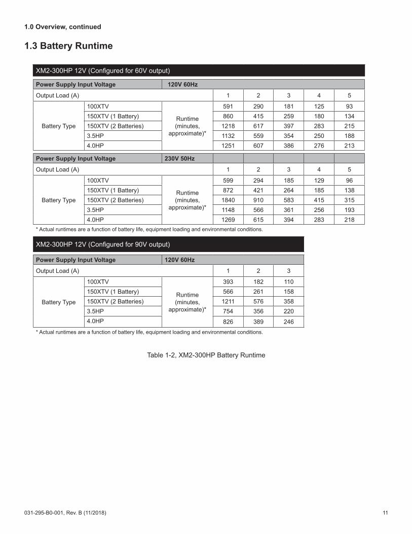
1.3 Battery Runtime
Table 1-2, XM2-300HP Battery Runtime
1.0 Overview, continued
XM2-300HP 12V (Configured for 60V output)
Power Supply Input Voltage 120V 60Hz
Output Load (A) 1 2 3 4 5
Battery Type
100XTV
Runtime (minutes,
approximate)*
591 290 181 125 93150XTV (1 Battery) 860 415 259 180 134150XTV (2 Batteries) 1218 617 397 283 2153.5HP 1132 559 354 250 1884.0HP 1251 607 386 276 213
Power Supply Input Voltage 230V 50Hz
Output Load (A) 1 2 3 4 5
Battery Type
100XTV
Runtime (minutes,
approximate)*
599 294 185 129 96150XTV (1 Battery) 872 421 264 185 138150XTV (2 Batteries) 1840 910 583 415 3153.5HP 1148 566 361 256 1934.0HP 1269 615 394 283 218
* Actual runtimes are a function of battery life, equipment loading and environmental conditions.
XM2-300HP 12V (Configured for 90V output)
Power Supply Input Voltage 120V 60Hz
Output Load (A) 1 2 3
Battery Type
100XTV
Runtime (minutes,
approximate)*
393 182 110150XTV (1 Battery) 566 261 158150XTV (2 Batteries) 1211 576 3583.5HP 754 356 2204.0HP 826 389 246
* Actual runtimes are a function of battery life, equipment loading and environmental conditions.

12 031-295-B0-001, Rev. B (11/2018)
1.0 Overview, continued
Table 1-3, XM3-910HP 36V Battery Runtime (Configured for 90V Output)
Table 1-4, XM3-615HP 36V Battery Runtime (Configured for 60V Output)
XM3-910HP 36V (Configured for 90V output)
Power Supply Input Voltage 120V 60Hz
Output Load (A) 1 2 3 4 5 6 7 8 9 10
Battery Type
18V4 (1 String)Runtime (minutes,
approximate)*
1021 580 397 295 234 191 160 137 119 104
100XTV (1 String) 1021 580 397 295 234 191 160 137 119 104
Power Supply Input Voltage 230V 50Hz
Output Load (A) 1 2 3 4 5 6 7 8 9 10
Battery Type18V4 (1 String)
Runtime (minutes, approximate)*
1021 579 398 298 234 191 160 137 119 104
100XTV (1 String) 1021 579 398 298 234 191 160 137 119 104
* Actual runtimes are a function of battery life, equipment loading and environmental conditions.
XM3-615HP 36V (Configured for 60V output)
Power Supply Input Voltage 120V 60HzOutput Load (A) 1 2 3 4 5 6 7 8 9 10 11 12 13 14 15
Battery Type18V4 (1 String) Runtime
(minutes, approximate)*
1183 753 548 425 345 288 246 214 188 167 149 135 123 112 103
100XTV (1 String) 1183 753 548 425 345 288 246 214 188 167 149 135 123 112 103
Power Supply Input Voltage 240V 60Hz
Output Load (A) 1 2 3 4 5 6 7 8 9 10 11 12 13 14 15
Battery Type18V4 (1 String) Runtime
(minutes, approximate)*
1168 743 545 423 345 287 246 213 187 166 149 134 122 112 103
100XTV (1 String) 1168 743 545 423 345 287 246 213 187 166 149 134 122 112 103
Power Supply Input Voltage 230V 50Hz
Output Load (A) 1 2 3 4 5 6 7 8 9 10 11 12 13 14 15
Battery Type18V4 (1 String) Runtime
(minutes, approximate)*
1384 831 589 449 360 299 252 218 191 169 151 136 123 112 103
100XTV (1 String) 1384 831 589 449 360 299 252 218 191 169 151 136 123 112 103
* Actual runtimes are a function of battery life, equipment loading and environmental conditions.

13031-295-B0-001, Rev. B (11/2018)
Enclosure ComponentsDescription Part NumberEnclosure Assembly, NPS 031-295-20
Installation ComponentsDescription Part NumberPole Mount Kit, Wooden Pole 746-032-20
Pole Mount Brackets, Wooden poles 744-670-20
Pole Mount Kit, Steel/Concrete poles 746-032-20
Brackets, pole mount, concrete/steel poles 591-557-20
Kit, Wall installation 746-034-20
Kit, Rack mounting 746-033-20
Kit, Indoor cover 746-036-20
Kit, Battery Cable, 36Vdc 746-038-20
Optional ComponentsDescription Part NumberLA-P-120T 162-046-10
Surge Protector, 75 Ohm FF w/ground 162-028-10
Line Cord (Indoor version only) 874-540-38
Kit, optional Inline Fuse 746-039-20
Sliding tray, Battery (100XTV Batteries only) 746-030-20
AlphaGuard CMT-3SC 36V 012-306-20
Table 1-5, Parts List
1.4 Parts List1.0 Overview, continued
14 031-295-B0-001, Rev. B (11/2018)
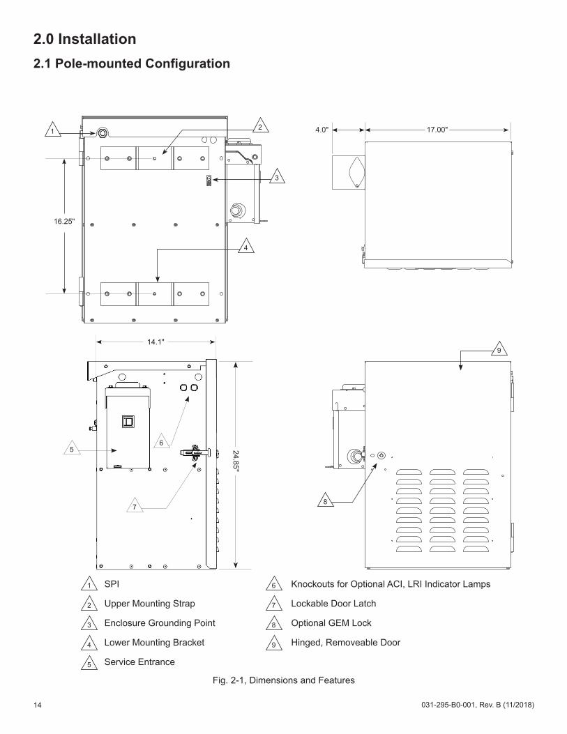
Fig. 2-1, Dimensions and Features
16.25"
3
2
4
1
8
9
6
2
1
3
4
7
8
9
5
2.0 Installation2.1 Pole-mounted Configuration
4.0" 17.00"
65
7
24.85"14.1"
SPI
Upper Mounting Strap
Enclosure Grounding Point
Lower Mounting Bracket
Service Entrance
Knockouts for Optional ACI, LRI Indicator Lamps
Lockable Door Latch
Optional GEM Lock
Hinged, Removeable Door
15031-295-B0-001, Rev. B (11/2018)
2.0 Installation, continued
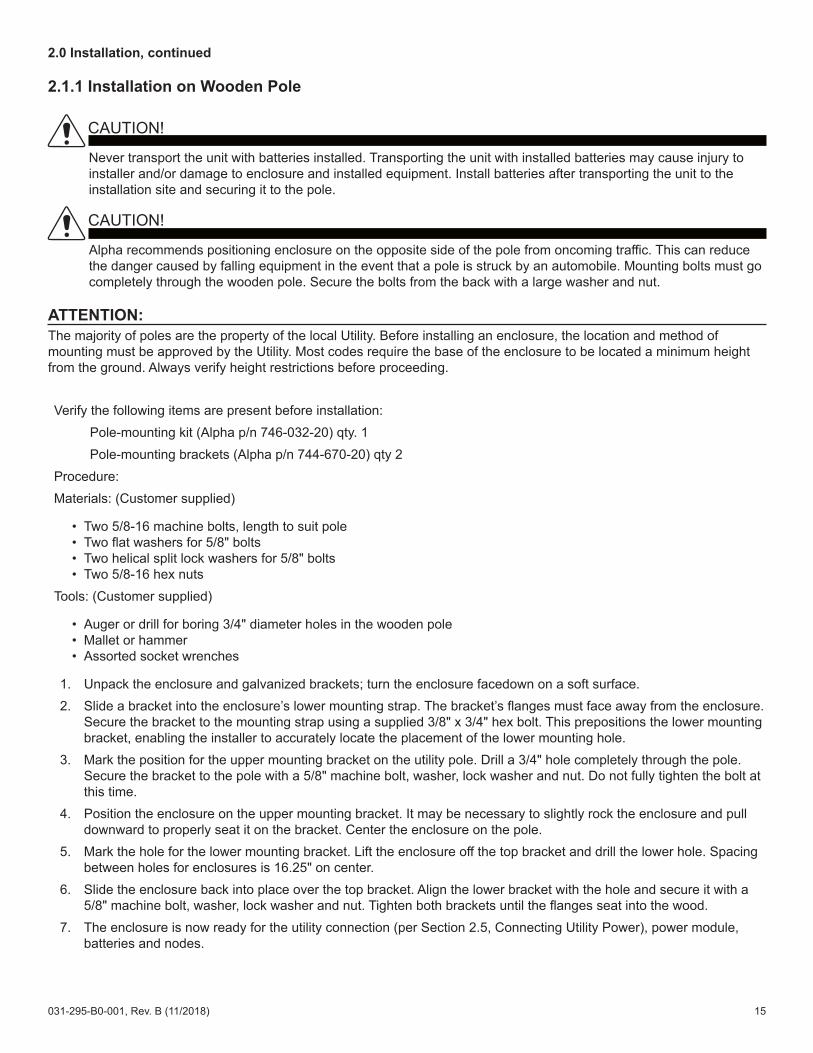
2.1.1 Installation on Wooden Pole
Verify the following items are present before installation: Pole-mounting kit (Alpha p/n 746-032-20) qty. 1 Pole-mounting brackets (Alpha p/n 744-670-20) qty 2Procedure:Materials: (Customer supplied)
• Two 5/8-16 machine bolts, length to suit pole• Two flat washers for 5/8" bolts• Two helical split lock washers for 5/8" bolts• Two 5/8-16 hex nuts
Tools: (Customer supplied)
• Auger or drill for boring 3/4" diameter holes in the wooden pole• Mallet or hammer• Assorted socket wrenches
1. Unpack the enclosure and galvanized brackets; turn the enclosure facedown on a soft surface.2. Slide a bracket into the enclosure’s lower mounting strap. The bracket’s flanges must face away from the enclosure.
Secure the bracket to the mounting strap using a supplied 3/8" x 3/4" hex bolt. This prepositions the lower mounting bracket, enabling the installer to accurately locate the placement of the lower mounting hole.
3. Mark the position for the upper mounting bracket on the utility pole. Drill a 3/4" hole completely through the pole. Secure the bracket to the pole with a 5/8" machine bolt, washer, lock washer and nut. Do not fully tighten the bolt at this time.
4. Position the enclosure on the upper mounting bracket. It may be necessary to slightly rock the enclosure and pull downward to properly seat it on the bracket. Center the enclosure on the pole.
5. Mark the hole for the lower mounting bracket. Lift the enclosure off the top bracket and drill the lower hole. Spacing between holes for enclosures is 16.25" on center.
6. Slide the enclosure back into place over the top bracket. Align the lower bracket with the hole and secure it with a 5/8" machine bolt, washer, lock washer and nut. Tighten both brackets until the flanges seat into the wood.
7. The enclosure is now ready for the utility connection (per Section 2.5, Connecting Utility Power), power module, batteries and nodes.
The majority of poles are the property of the local Utility. Before installing an enclosure, the location and method of mounting must be approved by the Utility. Most codes require the base of the enclosure to be located a minimum height from the ground. Always verify height restrictions before proceeding.
ATTENTION:
Never transport the unit with batteries installed. Transporting the unit with installed batteries may cause injury to installer and/or damage to enclosure and installed equipment. Install batteries after transporting the unit to the installation site and securing it to the pole.
CAUTION!
Alpha recommends positioning enclosure on the opposite side of the pole from oncoming traffic. This can reduce the danger caused by falling equipment in the event that a pole is struck by an automobile. Mounting bolts must go completely through the wooden pole. Secure the bolts from the back with a large washer and nut.
CAUTION!
16 031-295-B0-001, Rev. B (11/2018)
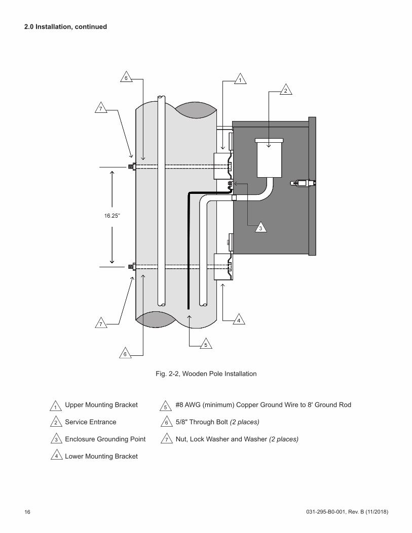
Fig. 2-2, Wooden Pole Installation
5
2
1
3
4
6
7
2.0 Installation, continued
Upper Mounting Bracket
Service Entrance
Enclosure Grounding Point
Lower Mounting Bracket
#8 AWG (minimum) Copper Ground Wire to 8' Ground Rod
5/8" Through Bolt (2 places)
Nut, Lock Washer and Washer (2 places)

17031-295-B0-001, Rev. B (11/2018)
Verify the following items are present before installation:
Pole mounting kit (Alpha p/n 746-032-20) qty. 1Pole mounting bracket kit (Alpha p/n 591-557-20) qty. 1 (contains 2 brackets)
Materials:Two customer-supplied stainless steel banding (or equivalent), rated to support loaded enclosure and sized for pole diameter.
Tools:Assorted socket wrenches
Procedure:1. Unpack the enclosure and galvanized brackets; turn the enclosure facedown on a soft surface.2. Slide a bracket up through the enclosure’s lower mounting strap(s). The bracket’s flanges must face away from
the enclosure. Secure the bracket to the mounting strap using a supplied 3/8" x 3/4" hex bolt. This prepositions the lower mounting bracket, enabling the installer to accurately locate the placement of the lower mounting hole.
3. Position the Upper mounting bracket on the pole and secure using a pole strap.4. Position the enclosure on the upper mounting bracket. It may be necessary to slightly rock the enclosure and pull
downward to properly seat it on the bracket. Center the enclosure on the pole.5. Secure the Lower mounting bracket on the pole using a pole strap. Spacing between mounting straps for
enclosures is 16.25" on center.6. The enclosure is now ready for the utility connection (per Section 2.5, Connecting Utility Power), power module,
batteries and nodes.
2.0 Installation, continued
2.1.2 Installation on Steel/Concrete Pole
The majority of poles are the property of the local Utility. Before installing an enclosure, the location and method of mounting must be approved by the Utility. Most codes require the base of the enclosure to be located a minimum height from the ground. Always verify height restrictions before proceeding.
ATTENTION:
Never transport the unit with batteries installed. Transporting the unit with installed batteries may cause injury to installer and/or damage to enclosure and installed equipment. Install batteries after transporting the unit to the installation site and securing it to the pole.
CAUTION!
Alpha recommends positioning enclosure on the opposite side of the pole from oncoming traffic. This can reduce the danger caused by falling equipment in the event that a pole is struck by an automobile. Mounting bolts must go completely through the wooden pole. Secure the bolts from the back with a large washer and nut.
CAUTION!
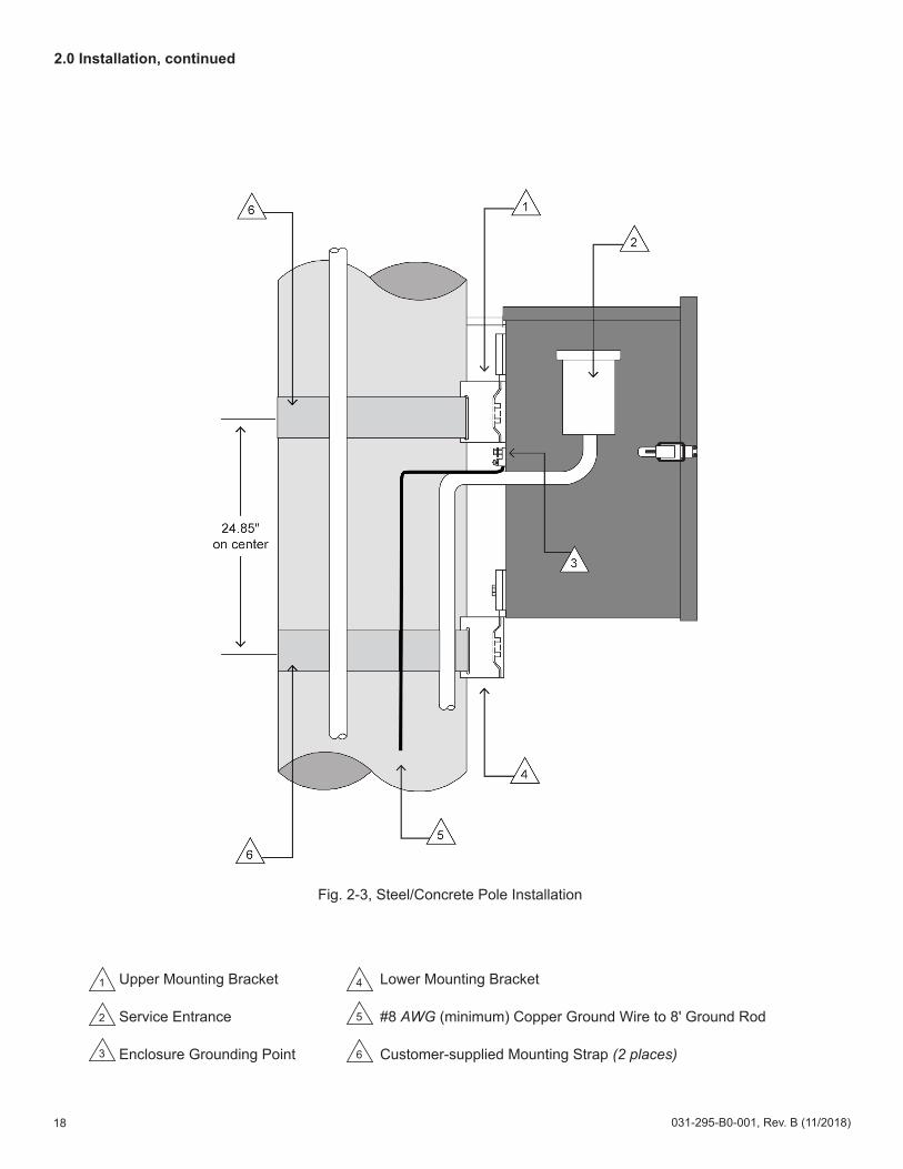
18 031-295-B0-001, Rev. B (11/2018)
52
1
3
4
6
Fig. 2-3, Steel/Concrete Pole Installation
2.0 Installation, continued
Upper Mounting Bracket
Service Entrance
Enclosure Grounding Point
Lower Mounting Bracket
#8 AWG (minimum) Copper Ground Wire to 8' Ground Rod
Customer-supplied Mounting Strap (2 places)

19031-295-B0-001, Rev. B (11/2018)
2.2 Rack-mounted Configuration
2.0 Installation, continued
1.0" 1.0"
Mounting tabs set for 19" rack
17.00"
19.00"
1
14.1"
1
1
1
Mounting tabs set for 23" rack
2.0" 2.0"17.00"
23.00"
24.85"
14.1"6
3
4
5
2
1 Mounting locations for SPI2 Enclosure ground point3 Knockouts for ACI, LRI Indicator lamps
4 Lockable door latch5 Optional GEM lock6 Hinged, removeable door
Fig. 2-4, Dimensions, Rack-mounted NPS Enclosure
2
1
3
5
4
6

20 031-295-B0-001, Rev. B (11/2018)
2.0 Installation, continued
2.2.1 Installation Procedure
Tools required: • 3/8" wrench and socket• Torque wrench (for 36 in-lbs spec.)
Verify the following are on hand:• Kit, Cover, Indoor (Alpha p/n 746-036-20) • Kit, Rack mounting (Alpha p/n 746-033-20) • Customer-supplied mounting hardware
Verify the equipment rack is securely bolted to the floor and in areas of seismic activity, the mounting method should meet Zone-4 seismic standards or better.Verify the batteries to be installed in the system are fully charged prior to installation.
1. Remove lid and door from enclosure. Set aside.2. Orient the rack mounting tabs as shown below to fit the equipment rack and attach rack mounting tabs to sides of
enclosure (1/4-20 hardware) tighten to 36 in-lbs.3. While one installer lifts and holds the empty enclosure in place, start the mounting hardware (1/4-20 bolts, 6
places) in the corresponding holes in the rack. Tighten to 36 in-lbs.
Enclosure front
Mounting tabs set for 23" rack (as viewed from above)
Mounting tabs set for 19" rack (as viewed from above)
Enclosure front
The populated cabinet will weigh approximately 240 lbs [109kg]. Use all eight mounting bolts (4 per mounting tab) to securely hold the enclosure in place.
CAUTION!
21031-295-B0-001, Rev. B (11/2018)
2.0 Installation, continued
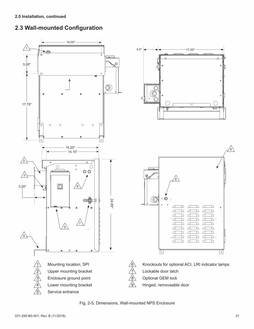
2.3 Wall-mounted Configuration
17.00"4.0"
16.00"
5.00"
17.75"
1
3.20"
24.85"
14.10"15.20"
6
7
3
5
2
4
8
9
Fig. 2-5, Dimensions, Wall-mounted NPS Enclosure
1 Mounting location, SPI2 Upper mounting bracket3 Enclosure ground point4 Lower mounting bracket5 Service entrance
6 Knockouts for optional ACI, LRI indicator lamps7 Lockable door latch8 Optional GEM lock9 Hinged, removeable door
22 031-295-B0-001, Rev. B (11/2018)
2.0 Installation, continued
2.3.1 Installation
Verify the following are on hand before installation:• Kit, Mounting, Wall (Alpha p/n 746-034-20) • Customer-supplied mounting hardware
Tools required:• 3/8" wrench and socket• Stud finder• Level • Hand drill with 5/32" bit
1. Remove the lid and door of the enclosure and set aside.2. Use stud finder to locate centers of two studs and mark.3. Hold upper bracket to located centers and mark the two lower holes at this time.4. Drill 4 5/32" pilot holes at the marks.5. Use 4 3/4" x 2-3/4" lagbolts to fasten the bracket to the wall.6. Attach the lower mounting brackets to the enclosure.7. Attach the enclosure to the upper mounting bracket.8. Mark the holes (on stud center) for the lower mounting brackets and drill 5/32" pilot holes.9. Use the 1/4" x 1-1/2" lagbolts to secure lower brackets to the wall.10. Installation complete. The enclosure is now ready for utility wiring and installation of equipment.
The populated cabinet will weigh approximately 240 lbs [109kg]. Direct mounting to wall studs is required.
CAUTION!!

23031-295-B0-001, Rev. B (11/2018)
2.0 Installation, continued
2.4 Floor-mounted Configuration
4.0" 17.00"14.10"15.20"
24.85"
52
1
4
3
6
14.10"
2.00" 6.50" 6.50"
7
7
Fig. 2-6, Dimensions, Floor-mounted NPS Enclosure
1 Lockable door latch2 Knockouts for ACI/LRI Indicator lamps3 Service entrance4 Enclosure ground point5 Optional GEM lock6 Hinged, removeable door7 Mounting locations for SPI
24 031-295-B0-001, Rev. B (11/2018)
2.0 Installation, continued
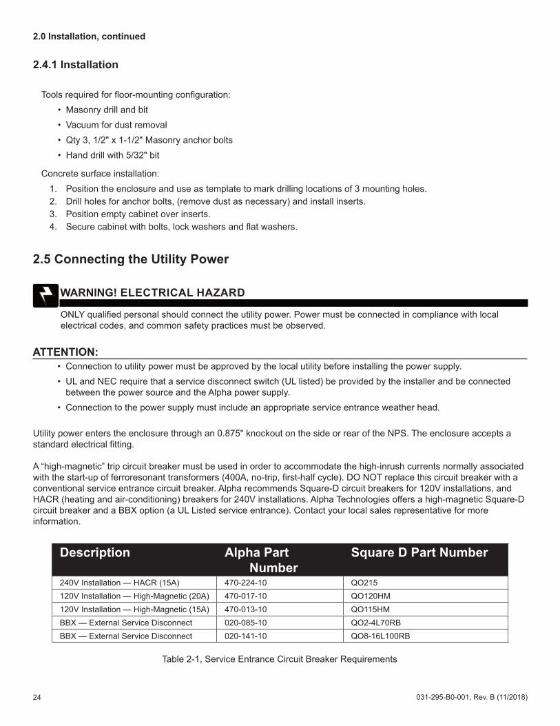
2.4.1 Installation
Tools required for floor-mounting configuration:• Masonry drill and bit• Vacuum for dust removal• Qty 3, 1/2" x 1-1/2" Masonry anchor bolts• Hand drill with 5/32" bit
Concrete surface installation:1. Position the enclosure and use as template to mark drilling locations of 3 mounting holes.2. Drill holes for anchor bolts, (remove dust as necessary) and install inserts.3. Position empty cabinet over inserts.4. Secure cabinet with bolts, lock washers and flat washers.
2.5 Connecting the Utility Power
Utility power enters the enclosure through an 0.875" knockout on the side or rear of the NPS. The enclosure accepts a standard electrical fitting.
A “high-magnetic” trip circuit breaker must be used in order to accommodate the high-inrush currents normally associated with the start-up of ferroresonant transformers (400A, no-trip, first-half cycle). DO NOT replace this circuit breaker with a conventional service entrance circuit breaker. Alpha recommends Square-D circuit breakers for 120V installations, and HACR (heating and air-conditioning) breakers for 240V installations. Alpha Technologies offers a high-magnetic Square-D circuit breaker and a BBX option (a UL Listed service entrance). Contact your local sales representative for more information.
Description Alpha Part Number
Square D Part Number
240V Installation — HACR (15A) 470-224-10 QO215120V Installation — High-Magnetic (20A) 470-017-10 QO120HM120V Installation — High-Magnetic (15A) 470-013-10 QO115HMBBX — External Service Disconnect 020-085-10 QO2-4L70RBBBX — External Service Disconnect 020-141-10 QO8-16L100RB
• Connection to utility power must be approved by the local utility before installing the power supply.• UL and NEC require that a service disconnect switch (UL listed) be provided by the installer and be connected
between the power source and the Alpha power supply.• Connection to the power supply must include an appropriate service entrance weather head.
ATTENTION:
ONLY qualified personal should connect the utility power. Power must be connected in compliance with local electrical codes, and common safety practices must be observed.
WARNING! ELECTRICAL HAZARD
Table 2-1, Service Entrance Circuit Breaker Requirements
25031-295-B0-001, Rev. B (11/2018)
2.0 Installation, continued
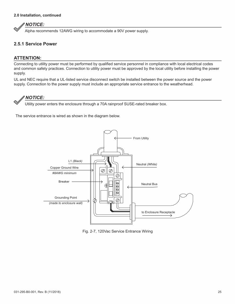
Alpha recommends 12AWG wiring to accommodate a 90V power supply.NOTICE::
2.5.1 Service Power
The service entrance is wired as shown in the diagram below.
Fig. 2-7, 120Vac Service Entrance Wiring
Connecting to utility power must be performed by qualified service personnel in compliance with local electrical codes and common safety practices. Connection to utility power must be approved by the local utility before installing the power supply.UL and NEC require that a UL-listed service disconnect switch be installed between the power source and the power supply. Connection to the power supply must include an appropriate service entrance to the weatherhead.
ATTENTION:
Utility power enters the enclosure through a 70A rainproof SUSE-rated breaker box.NOTICE:
to Enclosure Receptacle
Neutral Bus
Neutral (White)
From Utility
L1 (Black)
Copper Ground Wire
#8AWG minimum
Breaker
Grounding Point
(made to enclosure wall)

26 031-295-B0-001, Rev. B (11/2018)
Fig. 2-8, 520-R Receptacle Wiring
2.0 Installation, continued
NEUTRAL (White) L1 (Black)
GROUND (Green)

27031-295-B0-001, Rev. B (11/2018)
2.6 Connecting the Coaxial Cable2.6.1 Coaxial Cable Surge Protector Installation Instructions
Alpha recommends using coaxial surge suppression for enclosure protection. The Coaxial Surge Protector (Alpha p/n 162-028-10) includes 75 ohm surge suppressor, and mounting hardware. As shown below, the Surge Protector can be mounted in either of two locations on the cabinet.
Required Tools:• Phillips screwdriver• 3/8" socket and driver• Hammer • Punch
1. Remove one of the 3/8" knockouts located in the upper rear (or right side) of the enclosure with a hammer and punch.
2. Attach the surge protector to the inside of the enclosure wall with the provided hardware. The "Customer" connection will protrude from the enclosure.
3. Verify the star washers included in the kit are firmly in contact with the enclosure wall for proper grounding.
Fig. 2-9, Surge Protector mounting locations
Customer connection
Surge Protector
Customer connection
Surge Protector
2.0 Installation, continued
28 031-295-B0-001, Rev. B (11/2018)
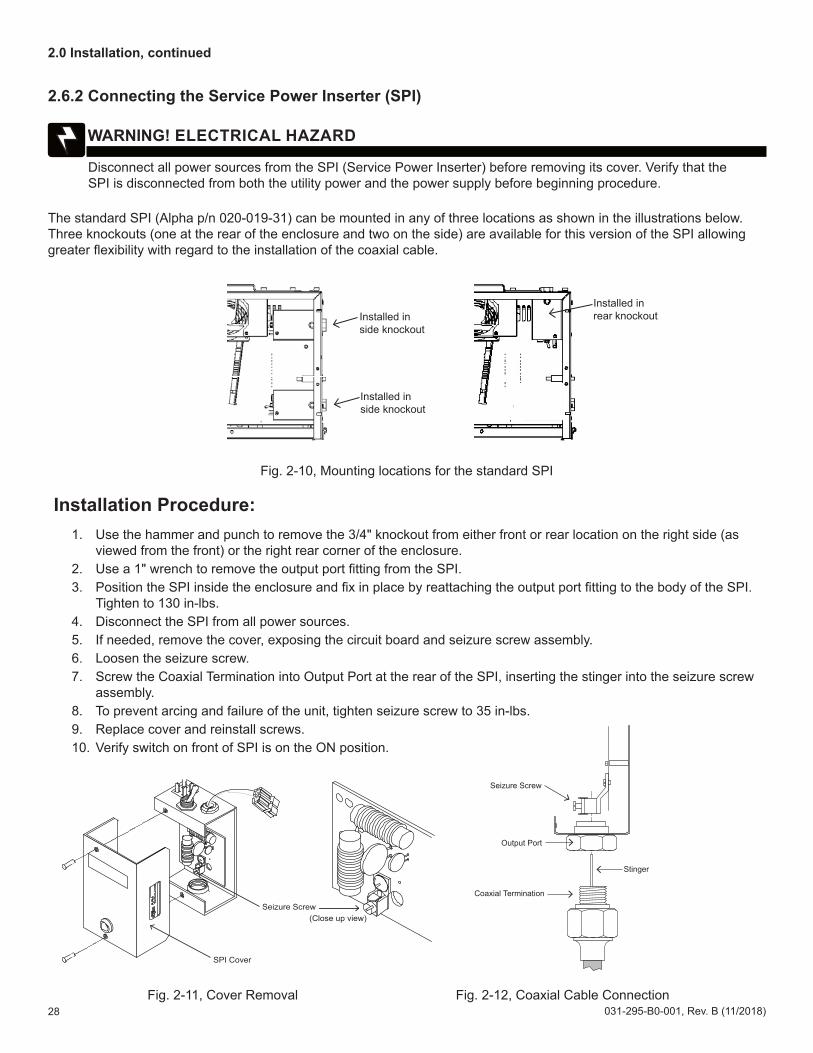
2.6.2 Connecting the Service Power Inserter (SPI)
The standard SPI (Alpha p/n 020-019-31) can be mounted in any of three locations as shown in the illustrations below. Three knockouts (one at the rear of the enclosure and two on the side) are available for this version of the SPI allowing greater flexibility with regard to the installation of the coaxial cable.
Fig. 2-10, Mounting locations for the standard SPI
Installation Procedure:1. Use the hammer and punch to remove the 3/4" knockout from either front or rear location on the right side (as
viewed from the front) or the right rear corner of the enclosure.2. Use a 1" wrench to remove the output port fitting from the SPI.3. Position the SPI inside the enclosure and fix in place by reattaching the output port fitting to the body of the SPI.
Tighten to 130 in-lbs.4. Disconnect the SPI from all power sources.5. If needed, remove the cover, exposing the circuit board and seizure screw assembly.6. Loosen the seizure screw.7. Screw the Coaxial Termination into Output Port at the rear of the SPI, inserting the stinger into the seizure screw
assembly. 8. To prevent arcing and failure of the unit, tighten seizure screw to 35 in-lbs.9. Replace cover and reinstall screws.10. Verify switch on front of SPI is on the ON position.
Fig. 2-11, Cover Removal Fig. 2-12, Coaxial Cable Connection
2.0 Installation, continued
Disconnect all power sources from the SPI (Service Power Inserter) before removing its cover. Verify that the SPI is disconnected from both the utility power and the power supply before beginning procedure.
WARNING! ELECTRICAL HAZARD
Installed in side knockout
Installed in side knockout
Installed in rear knockout
Seizure Screw
Output Port
Coaxial Termination
Stinger
Seizure Screw
SPI Cover
(Close up view)

29031-295-B0-001, Rev. B (11/2018)
2.6.3 Connecting the Service Power Inserter-RF (SPI-RF)
The SPI-RF (Alpha p/n 021-080-20 for the XM2, XM3) (Alpha p/n 021-080-21 for the XM2-300HP) can be mounted in either of the two locations as shown below.
Tools required:• Hammer• Punch• 1" wrench
Installation Procedure:1. Use the hammer and punch to remove the 3/4" knockout from either the right side (as viewed from the front) or
the right rear corner of the enclosure.2. Use a 1" wrench to remove the output port fitting from the SPI-RF.3. Position the SPI-RF inside the enclosure and fix in place by reattaching the output port fitting to the body of the
SPI-RF.4. Disconnect the SPI-RF from all power sources.5. Remove the access port cover, exposing the circuit board and seizure screw assembly.6. Loosen the seizure screw.7. Screw the Coaxial Termination into Output Port at the rear of the SPI-RF, inserting the stinger into the seizure
screw assembly.8. Tighten seizure screw to 35 in-lbs.9. Replace access port cover and reinstall screws.10. Verify switch on top of SPI-RF is on the ON position.
Fig. 2-13, Mounting locations for the SPI-RF
2.0 Installation, continued
Output Port Fitting
Output Port Fitting
Access Ports

30 031-295-B0-001, Rev. B (11/2018)
2.7 Battery Installation
The following precautions must be observed when maintaining batteries:
• Remove all personal metal objects (watches, rings, etc.).• Use insulated tools.• Wear eye protection and rubber gloves.• Observe circuit polarities.• Do not make or break live circuits.• Do not lay metal tools and hardware on top of the batteries.
The batteries are enclosed in cabinets with limited access. Again, extreme caution must be exercised when maintaining and collecting data on the battery system.
Battery Identification
Each battery contains a DATE CODE usually located on a sticker between the battery posts. This date code must be recorded in the battery’s maintenance log. If batteries other than those installed by Alpha are used, consult the battery’s documentation for date code type and placement.
Battery systems represent a risk of electrical shock and high short circuit currents.
WARNING! ELECTRICAL HAZARD
Fig. 2-14, Battery Identification Label
2.0 Installation, continued
Battery Date Code located in this box(1218 = DEC. 2018)
1218
31031-295-B0-001, Rev. B (11/2018)
Procedure:1. Place the batteries on the enclosure’s battery slide tray or battery shelf. Refer to Fig. 2-16 for correct battery
arrangement. Position the batteries to allow maximum ventilation space between the batteries.2. To make identification and record keeping easier, number and label the batteries. Record each battery’s number
and date code in the power supply maintenance log.3. Using the battery arrangement diagram as a reference, connect the batteries in series to achieve 36Vdc. Torque
terminal connections according to battery recommendations (see battery label for AlphaCell batteries).4. Check the polarity and voltage of the battery cable connector with a voltmeter to verify correct connections. DO
NOT connect the battery string or strings to the power supply at this time.5. The power supply battery charger collects battery temperature compensation information with a Remote
Temperature Sensor (RTS) or Precision Temperature Sensor (PTS). Refer to the diagrams and follow the instructions below that best matches your configuration:
• XM3 – Attach the PTS on the negative terminal of the #2 battery string.• XM2-300HP – Attach the DRTS (Dual Remote Temperature Probe) to the negative terminal of the battery.• XM2 – Attach the RTS about 1/3 of the way up from the battery’s base with a strong adhesive tape. Route the
RTS connector into the power supply compartment.
6. After attaching the sensor to the battery, DO NOT connect the RTS/PTS to the power supply at this time.7. Route the battery cable connector into the power supply compartment. DO NOT connect to the batteries to the
power supply at this time.
2.0 Installation, continued
To prevent arcing, never allow live battery cables to make contact with the enclosure. Disconnect battery leads, or wrap the cable lugs with electrical tape.
WARNING! ELECTRICAL HAZARD
In battery configurations made up of multiple battery strings, Alpha strongly recommends the use of in-line fuses.NOTICE:
Threaded insert terminals require the use of 3/4" bolts. The use of 1" bolts will seriously damage the battery. The only exception is the terminal with the large spacer for the in-line fuse link.
CAUTION!!
Recheck the polarity and voltage of the battery cable connector before proceeding. Connecting the battery string or strings to the power supply with incorrect polarity will cause a short-circuit, and possible equipment damage.
CAUTION!
2.7.1 Battery Installation Procedure

32 031-295-B0-001, Rev. B (11/2018)
Fig. 2-15, NPS Battery Wiring Diagram
2.0 Installation, continued
2.7.2 Battery Wiring Diagram
In-line Fuse (optional)(Alpha p/n 746-039-20)
RTS(Taped to side of battery for XM2)
12
3
Enclosure Front
100XTV Battery
100XTV Battery
100XTV Battery
Sliding battery tray (for use with 100XTV Batteries)(Alpha p/n 746-030-20)
Temperature Probe(Connected to XM2)
Battery Cable Connector(to XM2 Power Supply)
Battery Cable Kit (BCK):(Alpha p/n 746-038-20) BCK, 36Vdc
Red
(+)
Blac
k (-)
XM3
XM2
XM2-300HP
Battery Cable Connector(to XM2-300HP Power Supply)
12V
RED
(+)
BLAC
K (-)
DRTS / PTS
Battery Cable Connector(to XM2-300HP Power Supply)
12V12V
RED
(+)
BLAC
K (-)
DRTS / PTS
123
RED
(+)
BLAC
K (-)
Battery Cable Connector(to XM3 Power Supply)
PTS
In-line Fuse(optional)
(String -) 0V
A single 12Vdc battery Two 12Vdc batteries wired in parallel provide 12Vdc output with doube the Ah capacity of each individual battery.

33031-295-B0-001, Rev. B (11/2018)
Fig. 2-16, Hardware stack-up, Threaded Battery Insert
Fig. 2-17, Hardware stack-up, Threaded Battery Insert with Optional In-line use
Threaded insert terminals require the use of 3/4" bolts. The use of 1" bolts will seriously damage the battery. The only exception is the terminal with the large spacer for the in-line fuse link.
NOTICE:
Different batteries have different requirements. Threaded insert terminals require the use of specific bolts. The use of 1" bolts will seriously damage the battery. The only exception is the terminal with the large spacer for the in-line fuse link. Please refer to the battery manufacturer's threaded terminal requirements.
CAUTION!
2.0 Installation, continued
2.7.3 Battery Terminal Connections
Use the hardware supplied with the battery. The use of 1" bolts will seriously damage the battery. The only exception is the terminal with the large spacer for the in-line fuse link.
NOTICE:
Nut
Split WasherFlat Washer
Battery Cable
In-Line Fuse LinkFlat Washer
Bolt
Bolt
Flat WasherSplit Washer
Spacer
Battery Terminal
Bolt
Split Washer
Flat Washer
Battery Sense Cable
Battery CableBattery Terminal
34 031-295-B0-001, Rev. B (11/2018)
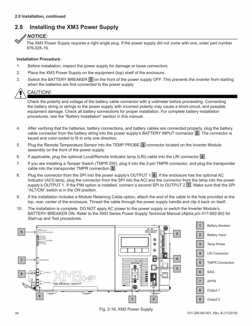
2.8 Installing the XM3 Power Supply
Installation Procedure:1. Before installation, inspect the power supply for damage or loose connectors.2. Place the XM3 Power Supply on the equipment (top) shelf of the enclosure.3. Switch the BATTERY BREAKER 1 on the front of the power supply OFF. This prevents the inverter from starting
when the batteries are first connected to the power supply.
4. After verifying that the batteries, battery connections, and battery cables are connected properly, plug the battery cable connector from the battery string into the power supply’s BATTERY INPUT connector 2 . The connector is keyed and color-coded to fit in only one direction.
5. Plug the Remote Temperature Sensor into the TEMP PROBE 3 connector located on the Inverter Module assembly on the front of the power supply.
6. If applicable, plug the optional Local/Remote Indicator lamp (LRI) cable into the LRI connector 4 .7. If you are installing a Tamper Switch (TMPR SW), plug it into the 2-pin TMPR connector, and plug the transponder
cable into the transponder TMPR connection 5 .8. Plug the connector from the SPI into the power supply’s OUTPUT 1 6 . If the enclosure has the optional AC
Indicator (ACI) lamp, plug the connector from the SPI into the ACI and the connector from the lamp into the power supply’s OUTPUT 1. If the PIM option is installed, connect a second SPI to OUTPUT 2 7 . Make sure that the SPI “ALT/ON” switch is in the ON position.
9. If the installation includes a Module Retaining Cable option, attach the end of the cable to the hole provided at the top, rear, center of the enclosure. Thread the cable through the power supply handle and clip it back on itself.
10. The installation is complete. DO NOT apply AC power to the power supply or switch the Inverter Module’s BATTERY BREAKER ON. Refer to the XM3 Series Power Supply Technical Manual (Alpha p/n 017-882-B0) for Start-up and Test procedures.
Check the polarity and voltage of the battery cable connector with a voltmeter before proceeding. Connecting the battery string or strings to the power supply with incorrect polarity may cause a short-circuit, and possible equipment damage. Check all battery connections for proper installation. For complete battery installation procedures, see the “Battery Installation” section in this manual.
CAUTION!!
2.0 Installation, continued
Fig. 2-18, XM3 Power Supply
1 Battery Breaker
2 Battery Input
3 Temp Probe
4 LRI Connector
5 TMPR Connection
6 SAG
7 APPS
8 Output 1
9 Output 2
i SMARTALPHAGUARD
ACTIVESTRG ASTRG B
STRG CSTRG D
ALARMS
ALPHA APPS
N
N
OUTPUT 1
OUTPUT 2
3
4
5
1 2
6
8
7
9
The XM3 Power Supply requires a right angle plug. If the power supply did not come with one, order part number 876-025-19.
NOTICE:

35031-295-B0-001, Rev. B (11/2018)
2.0 Installation, continued
2.9 Cooling Fan Kit Installation
Tools Required:• Phillips Screwdriver• Drill and bit for #6 screws
Installation Procedure: To install the optional NPS Fan Kit (Alpha p/n 745-101-20):
Fig. 2-19, Cooling fan installation configuration
2.10 Cooling Fan Kit RemovalTo remove the fan kit, follow the procedure below:
1. Open enclosure door and remove the enclosure lid.2. Verify power is removed from fan circuit.3. From inside the enclosure, remove the two #2 Phillips-head screws.4. Remove the fan housing.5. Disconnect the two Faston® connectors from the fan.6. Replace lid and close door.
i SMARTALPHAGUARD
ACTIVESTRG ASTRG B
STRG CSTRG D
ALARMS
ALPHA APPS
N
N
OUTPUT 1
OUTPUT 2
This procedure requires a service power supply such as the APP 9015S or APP 9022S (Alpha p/n 016-537-B0-002) to maintain power to the cable plant while fan is being installed.
NOTICE:
12 2
5
5
1
2
3
4
5
Open enclosure door and remove the enclosure lid.
Drill out holes on both sides of mesh.
Insert the fan through the top enclosure.
Attach the fan assembly to the two holes using the two #6-32 x 3/8" Phillips screws provided. Orient the fan assembly so that the exposed fan is up and the fan guard is down, as shown. Screw the screws in from the outside of the enclosure.
Plug one end of the fan’s Y cable into the SPI wire. Plug other end of the Y cable into the power supply’s OUTPUT 2 connector.
4
3
and

36 031-295-B0-001, Rev. B (11/2018)
3.0 Populating the Cabinet and Turn-up Checklist
Verify utility connections are correct. (Section 2.5, Connecting Utility Power)
Verify power supply is installed.
Verify batteries are wired according to the diagram on the enclosure door, and that the hardware is tightened to the manufacturer's specifications.
Verify the SPI, tamper switch and communications modules are connected. (Section 2.8, Installing the XM3 Power Supply)
Verify lid and door are installed.
Verify utility power is connected.
Verify battery string is connected to the XM3 Power Supply.
Turn on battery breaker.
Battery alarm is clear.
After completing the checklist, the unit is ready to be placed into service.

Alpha Technologies Alpha reserves the right to change specifications without notice.Alpha is a registered trademark of Alpha Technologies.
For more information visit www.alpha.com
© 2018 Alpha Technologies Inc. All Rights Reserved.
031-341-C0-001 Rev. B (11/2018)
Worldwide Corporate Offices
North AmericaTel: +1 360 647 2360Fax: +1 360 671 4936
EuropeTel: +49 9122 79889 0Fax: +49 9122 79889 21
Latin AmericaTel: +561 792.9651Fax: +561 792.7157
Asia PacificTel: +852 2736.8663Fax: +852 2199.7988


