29
Noise Cancelation for MIMO System Prepared by: Heba Hamad Rawia Zaid Rua Zaid Supervisor: Dr.Yousef Dama
| Date post: | 15-Jan-2016 |
| Category: |
Documents |
| Upload: | eleanor-oneal |
| View: | 224 times |
| Download: | 0 times |

Noise Cancelation for MIMO System
Prepared by: Heba Hamad Rawia Zaid
Rua Zaid Supervisor: Dr.Yousef Dama
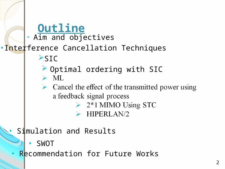
Outline• Aim and objectives
2
•Interference Cancellation TechniquesSIC Optimal ordering with SIC
• Simulation and Results
• SWOT• Recommendation for Future Works
3
Aims and Objectives
Present a method to cancel the interference that is caused by the transmitting antennas closely spaced to the receive antennas of the MIMO system.
4
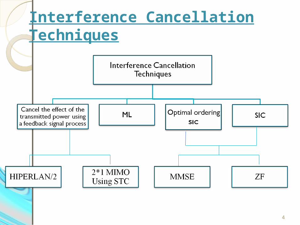
Interference Cancellation Techniques
4
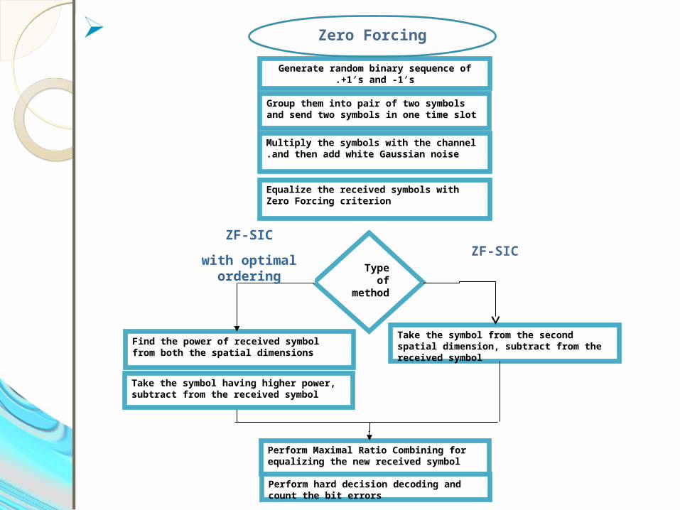
Generate random binary sequence of +1′s and -1′s.
Group them into pair of two symbols and send two symbols in one time slot
Multiply the symbols with the channel and then add white Gaussian noise.
Equalize the received symbols with Zero Forcing criterion
Find the power of received symbol from both the spatial dimensions
Take the symbol having higher power, subtract from the received symbol
Perform Maximal Ratio Combining for equalizing the new received symbol
Perform hard decision decoding and count the bit errors
Type of method
Take the symbol from the second spatial dimension, subtract from the received symbol
ZF-SIC
with optimal ordering
ZF-SIC
Zero Forcing
6
Generate random binary sequence of +1′s and -1′s.
Group them into pair of two symbols and send two symbols in one time slot
Multiply the symbols with the channel that add with and then add white Gaussian noise.
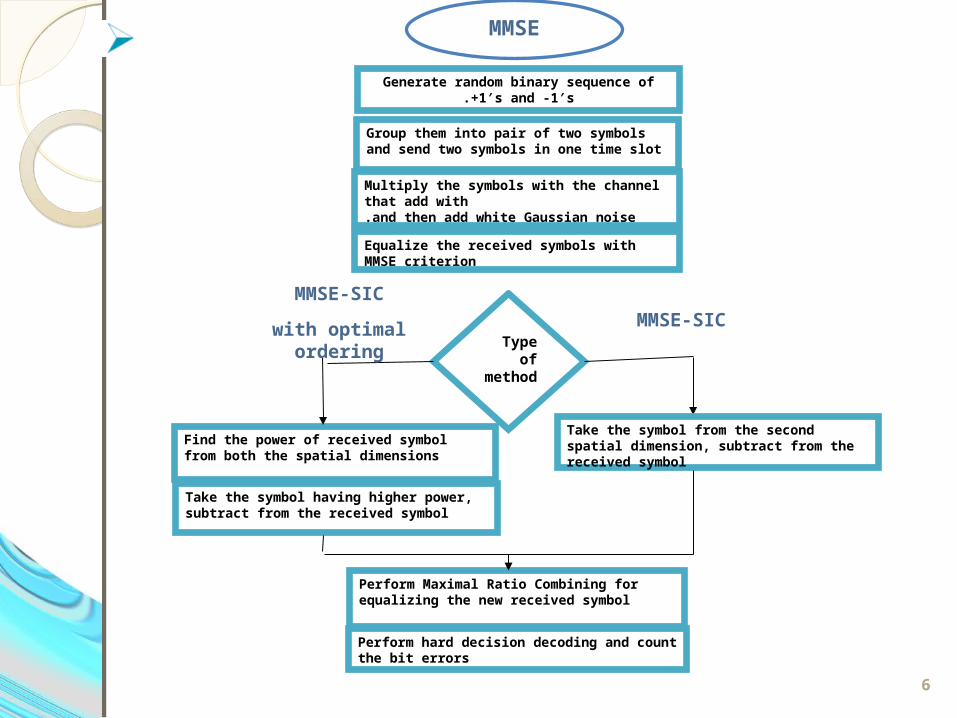
Equalize the received symbols with MMSE criterion
Find the power of received symbol from both the spatial dimensions
Take the symbol having higher power, subtract from the received symbol
Perform Maximal Ratio Combining for equalizing the new received symbol
Perform hard decision decoding and count the bit errors
Type of method
Take the symbol from the second spatial dimension, subtract from the received symbol
MMSE-SIC
with optimal ordering
MMSE-SIC
MMSE
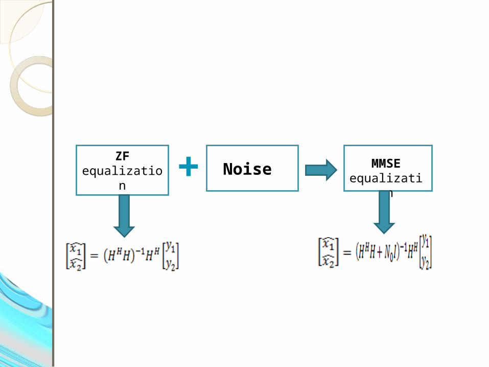
Noise ZF equalization
MMSE equalization+
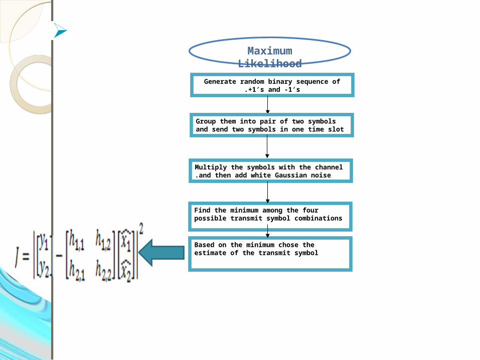
Generate random binary sequence of +1′s and -1′s.
Group them into pair of two symbols and send two symbols in one time slot
Multiply the symbols with the channel and then add white Gaussian noise.
Find the minimum among the four possible transmit symbol combinations
Based on the minimum chose the estimate of the transmit symbol
Maximum Likelihood
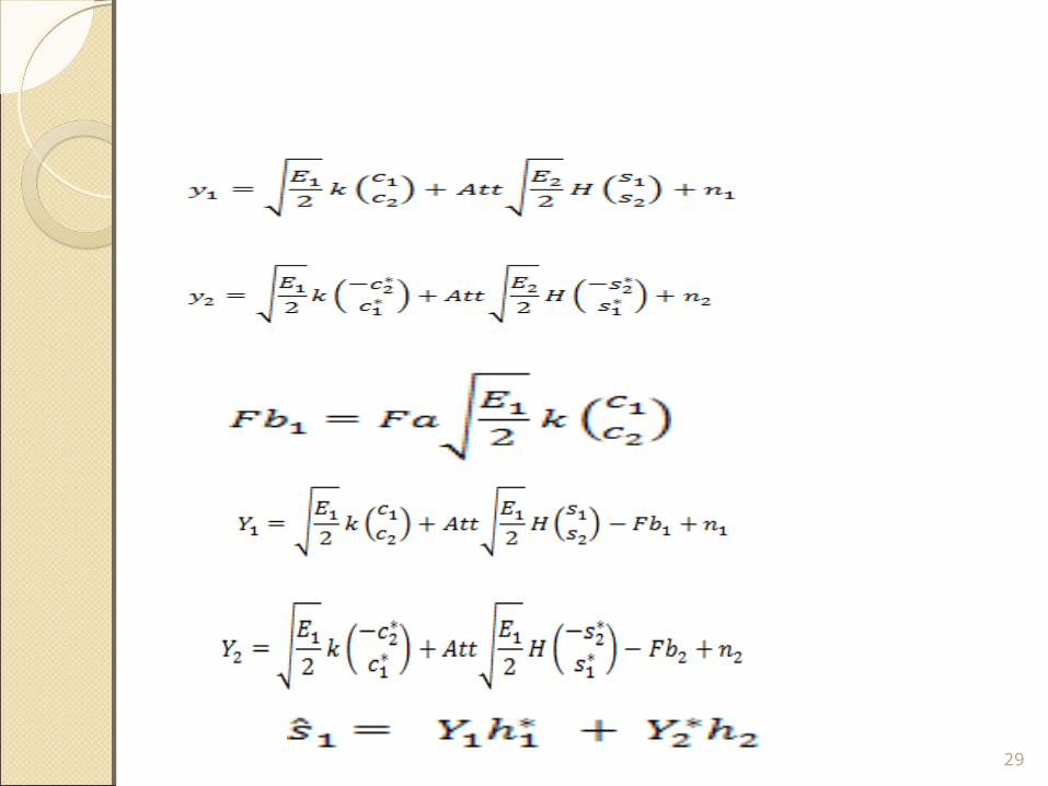
Cancel the effect of the transmitted power using a feedback signal process
o2*1 MIMO Using STC
oHIPERLAN/2
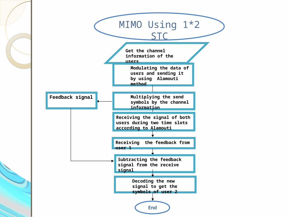
2*1 MIMO Using STC
Get the channel information of the users
Modulating the data of users and sending it by using Alamouti method
Multiplying the send symbols by the channel information
Receiving the signal of both users during two time slots according to Alamouti
Receiving the feedback from user 1
Subtracting the feedback signal from the receive signal
Feedback signal
Decoding the new signal to get the symbols of user 2
End
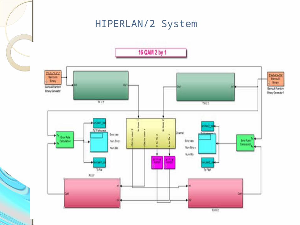
HIPERLAN/2 System
Simulation and Results
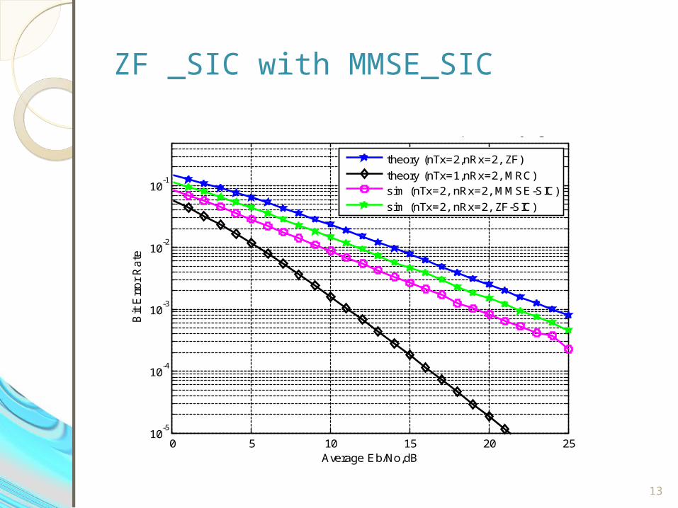
ZF _SIC with MMSE_SIC
13
0 5 10 15 20 2510
-5
10-4
10-3
10-2
10-1
Average Eb/No,dB
Bit E
rror
Rate
BER for BPSK modulation with 2x2 MIMO and MMSE-SIC equalizer (Rayleigh channel)
theory (nTx=2,nRx=2, ZF)
theory (nTx=1,nRx=2, MRC)sim (nTx=2, nRx=2, MMSE-SIC)
sim (nTx=2, nRx=2, ZF-SIC)
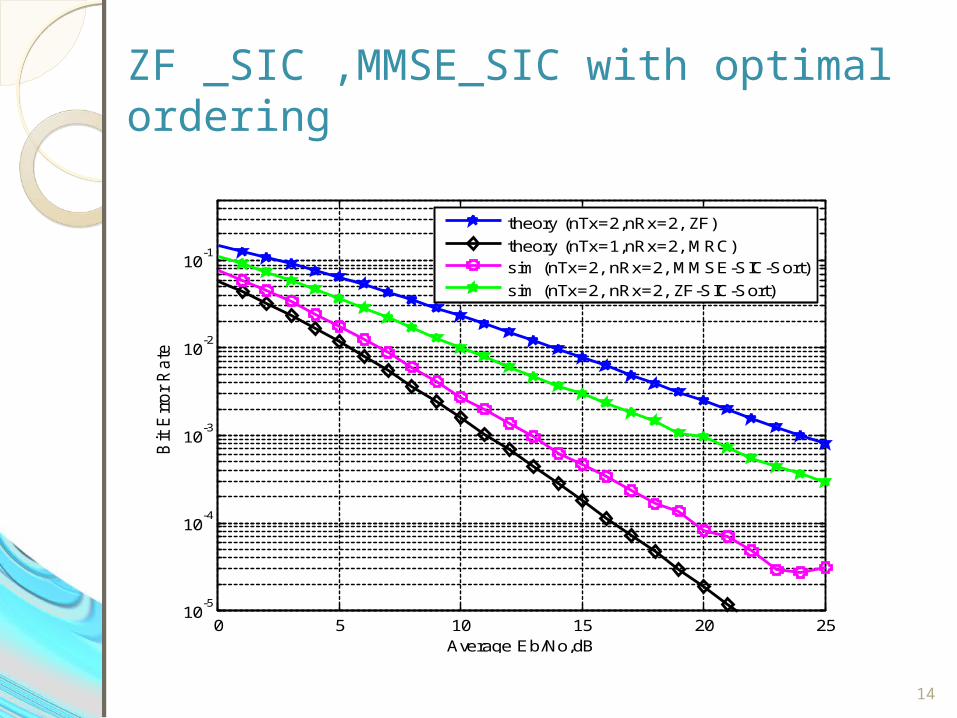
ZF _SIC ,MMSE_SIC with optimal ordering
14
0 5 10 15 20 2510
-5
10-4
10-3
10-2
10-1
Average Eb/No,dB
Bit E
rror
Rate
BER for BPSK modulation with 2x2 MIMO and MMSE-SIC equalizer (Rayleigh channel)
theory (nTx=2,nRx=2, ZF)
theory (nTx=1,nRx=2, MRC)sim (nTx=2, nRx=2, MMSE-SIC-Sort)
sim (nTx=2, nRx=2, ZF-SIC-Sort)
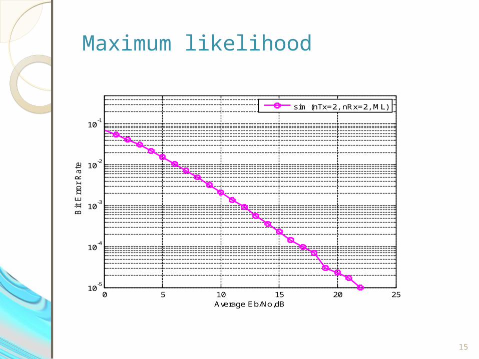
Maximum likelihood
15
0 5 10 15 20 2510
-5
10-4
10-3
10-2
10-1
Average Eb/No,dB
Bit E
rror
Rate
BER for BPSK modulation with 2x2 MIMO and ML equalizer (Rayleigh channel)
sim (nTx=2, nRx=2, ML)
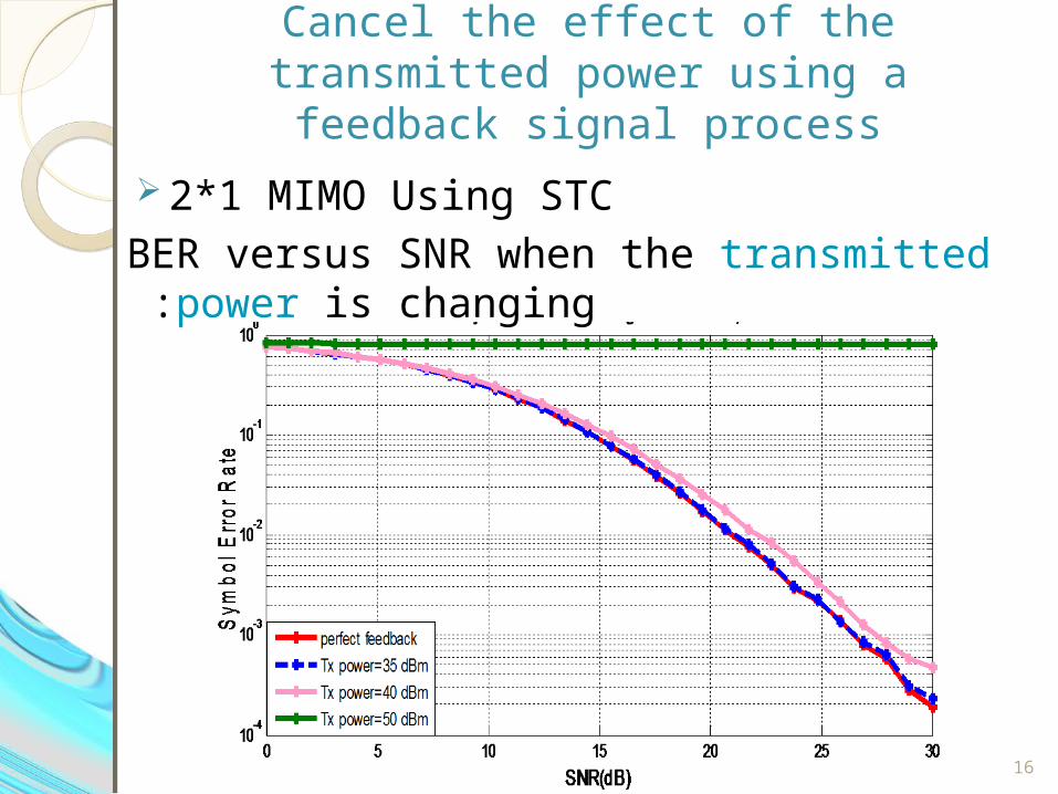
Cancel the effect of the transmitted power using a feedback signal process
2*1 MIMO Using STC
BER versus SNR when the transmitted power is changing :
16
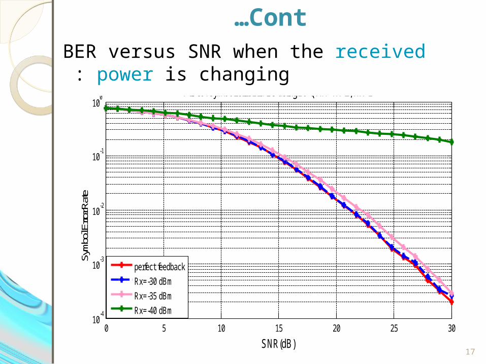
Cont…
17
BER versus SNR when the received power is changing :
0 5 10 15 20 25 3010
-4
10-3
10-2
10-1
100
Plot of symbol error rates using16-QAM Tx=2, Rx=1
SNR(dB)
Sym
bol E
rror R
ate
perfect feedback
Rx=-30 dBm
Rx=-35 dBm
Rx=-40 dBm
Cont…
18
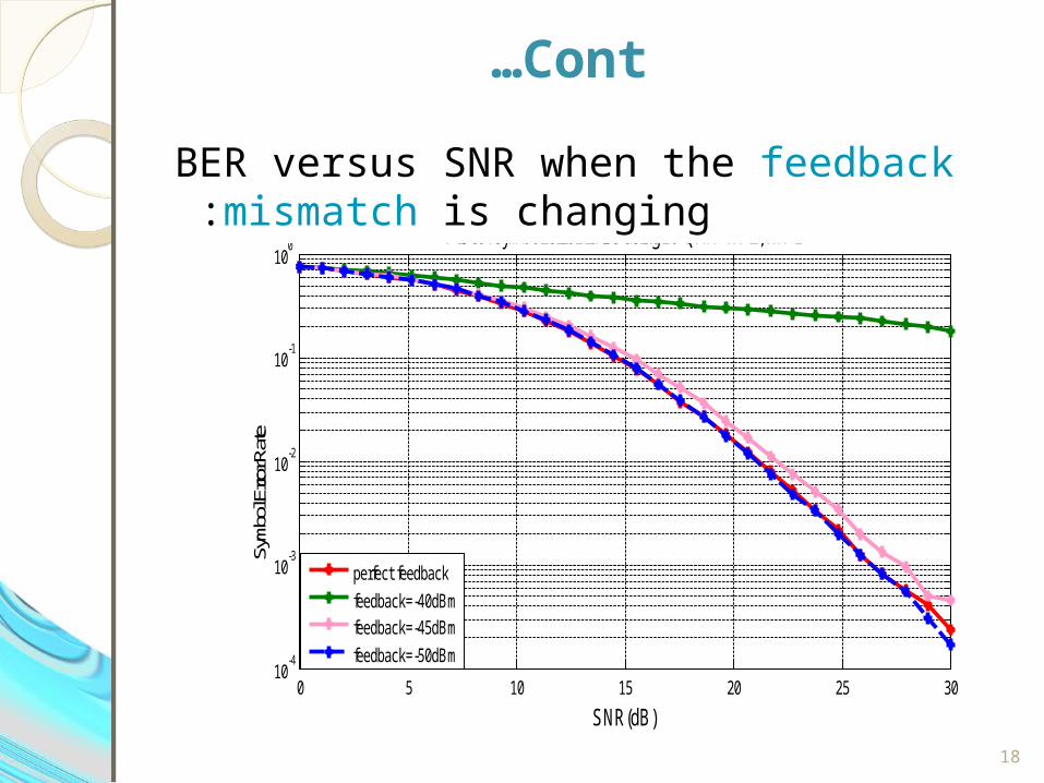
BER versus SNR when the feedback mismatch is changing :
0 5 10 15 20 25 3010
-4
10-3
10-2
10-1
100
Plot of symbol error rates using16-QAM Tx=2, Rx=1
SNR(dB)
Symb
ol Er
ror R
ate
perfect feedback
feedback=-40dBmfeedback=-45dBm
feedback=-50dBm
19
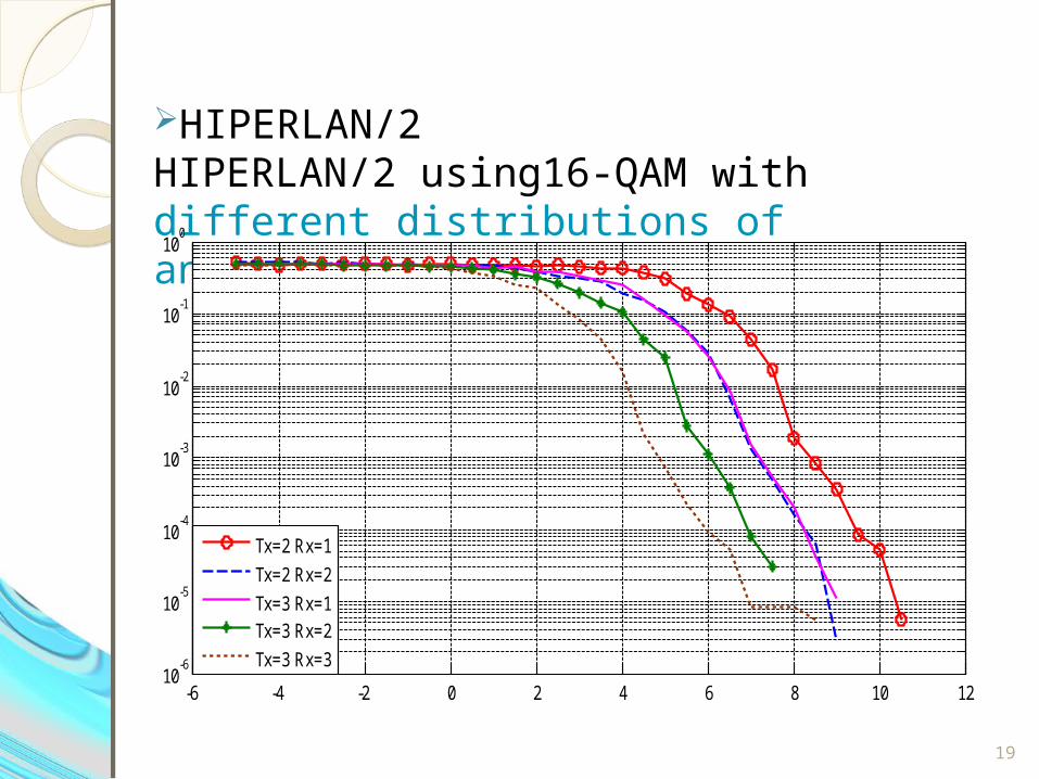
HIPERLAN/2 HIPERLAN/2 using16-QAM with different distributions of antennas:
-6 -4 -2 0 2 4 6 8 10 1210
-6
10-5
10-4
10-3
10-2
10-1
100
Tx=2 Rx=1
Tx=2 Rx=2
Tx=3 Rx=1Tx=3 Rx=2
Tx=3 Rx=3
Cont…
20
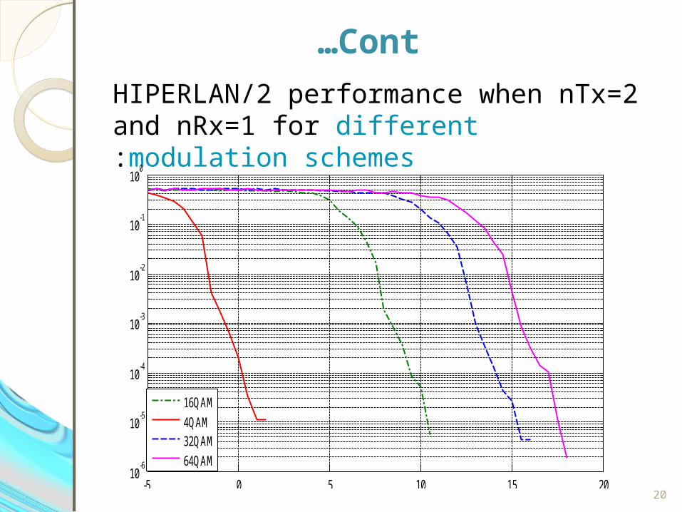
HIPERLAN/2 performance when nTx=2 and nRx=1 for different modulation schemes:
-5 0 5 10 15 2010
-6
10-5
10-4
10-3
10-2
10-1
100
16QAM
4QAM 32QAM
64QAM
Cont…
21
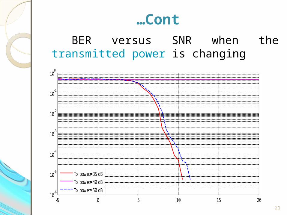
BER versus SNR when the transmitted power is changing
-5 0 5 10 15 2010
-6
10-5
10-4
10-3
10-2
10-1
100
Tx power=35 dB
Tx power=40 dB
Tx power=50 dB
Cont…
22
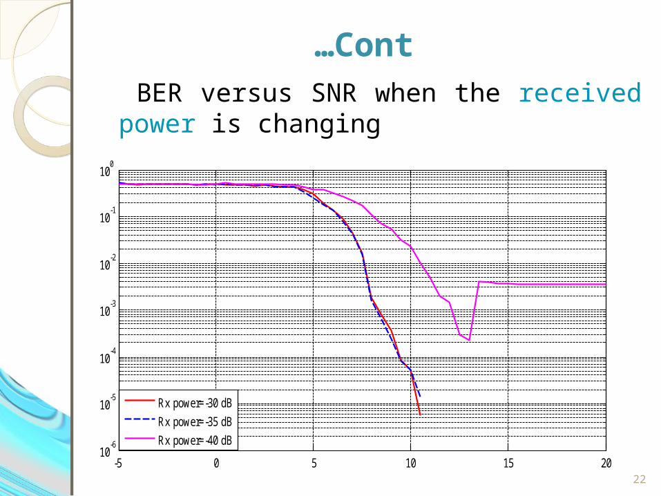
BER versus SNR when the received power is changing
-5 0 5 10 15 2010
-6
10-5
10-4
10-3
10-2
10-1
100
Rx power=-30 dB
Rx power=-35 dB
Rx power=-40 dB
Cont…
23
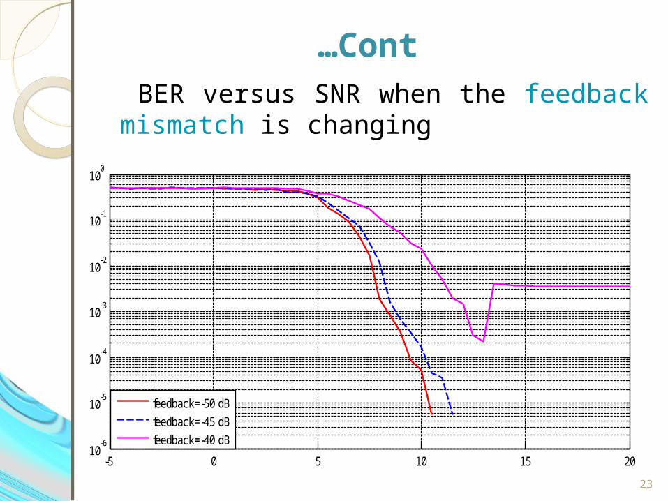
BER versus SNR when the feedback mismatch is changing
-5 0 5 10 15 2010
-6
10-5
10-4
10-3
10-2
10-1
100
feedback=-50 dB
feedback=-45 dB
feedback=-40 dB
Cont…
24
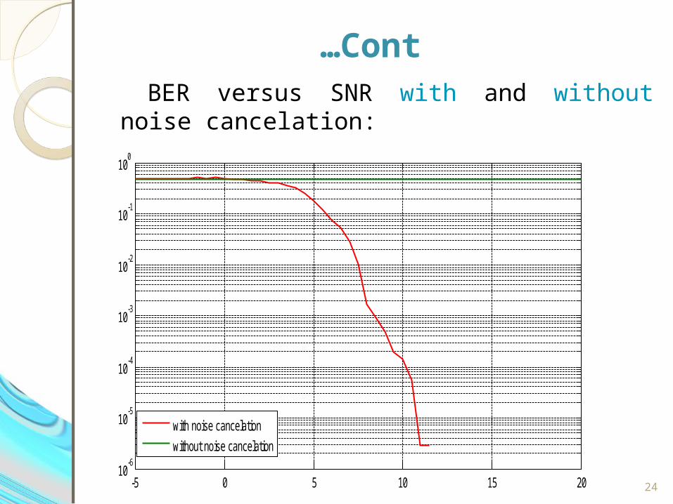
BER versus SNR with and without noise cancelation:
BER versus SNR
-5 0 5 10 15 2010
-6
10-5
10-4
10-3
10-2
10-1
100
with noise cancelation
without noise cancelation
s w
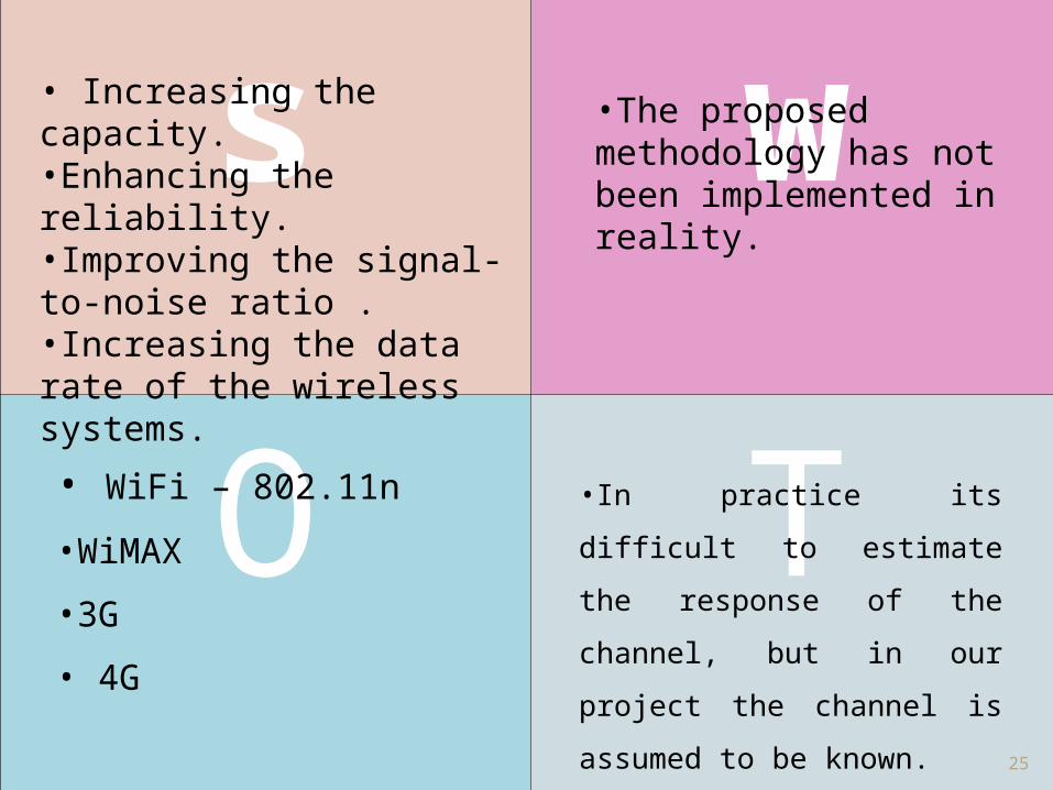
O T•In practice its difficult to estimate
the response of the channel, but in
our project the channel is assumed
to be known.
•The proposed methodology has not been implemented in reality.
• Increasing the capacity.•Enhancing the reliability.•Improving the signal-to-noise ratio .•Increasing the data rate of the wireless systems.
• WiFi – 802.11n
•WiMAX
•3G
• 4G
25
Recommendation for Future Works
• The suggested methodology can be implemented in reality then measuring the results and comparing it with the simulated results.
• Studying the performance of the system with other types of channels and other type of diversity code.
• studying the other types of antennas distributions in both transmitting and receiving sides.
26

27

28
29


