1 NOISE MITIGATION AND ATTENUATION FOR TEST CELLS WITH MULTIPLE SMALL ENGINES Jack B. Evans JEAcoustics / Engineered Vibration Acoustic & Noise Solutions, Austin, Texas, USA email: Evans<at>JEAcoustics.com A manufacturer of hand-held engine-powered equipment proposed construction of two test cells within their existing facility for simultaneous testing and operation of up to ten tools. Facility sys- tems will ventilate the enclosure with fresh air and recirculated tempered air, while engine exhaust and fumes are exhausted. Industrial hearing protection is required for workers within the cell while sound containment should minimize acoustical disturbance to nearby areas. Tools are to be sup- ported on stanchions 1–1.25 m (3-4 ft) above floor. Technicians may work, setting up engines for test while other engines are operating in the cells. Workers' hearing protection is governed by oc- cupational noise exposure limit of 85 dBA for eight hours, with 5-dB increase for each halving of time or proportional decrease for time exceeding eight hours. Individual engines with standard ex- haust mufflers operate up to 103 dBA. The owners desire not greater than 100 dBA at maximum capacity in the cell. To determine an "envelope" of noise conditions for design purposes, multiple sound spectrum source levels were determined for reverberant and free field conditions. Ventila- tion air handler and exhaust noise were determined for comparison with engine noise to determine additive contribution. Standard engine exhaust mufflers could not be modified for noise control, since the test facility was for development and validation of equipment for commercial markets. Noise control should avoid interference to equipment access for set-up, maintenance, monitoring or emergency. Various approaches and solutions were developed for room acoustics (spatial de- cay) and sound barriers (insertion loss), which could be implemented by design engineers. Materi- als and methods of construction were designed to achieve maximum practical spatial decay, and owner was provided recommendations for operational deployment of small partial barriers near operating engines. The owner was satisfied with post-occupancy operations and noise control re- sults for the test cell. Keywords: engine noise, absorption, barrier, attenuation 1. Introduction Noise control analysis and consultation was requested by engineering designers for two proposed product development test cells in an existing manufacturing facility for hand-held tools powered by small gasoline (petrol) engines, generically illustrated in Fig. 1. The facility would incorporate ten engine stands for set-up and simultaneous operation of small engines. Individual “normal” engine noise emissions with standard mufflers with could be up to 103 dBA. Six of ten engines were nor- mally expected to operate under, but all ten engines can be operated simultaneously. The room level could theoretically increase to 113 dBA, re: Eq. (1), with variance for room acoustic conditions. Sum = Lp 1 + 10 x log 10 (n) (1) Sum = overall level, Lp 1 = single source noise level and n = total number of sources at same sound level. Concerns included a) worker hearing conservation within the test cell and b) containment of sound to prevent disturbance or contribution to ambient noise levels to nearby spaces. In a dynamic
Transcript
1
NOISE MITIGATION AND ATTENUATION FOR TEST CELLS WITH MULTIPLE SMALL ENGINES Jack B. Evans JEAcoustics / Engineered Vibration Acoustic & Noise Solutions, Austin, Texas, USA email: Evans<at>JEAcoustics.com
A manufacturer of hand-held engine-powered equipment proposed construction of two test cells within their existing facility for simultaneous testing and operation of up to ten tools. Facility sys-tems will ventilate the enclosure with fresh air and recirculated tempered air, while engine exhaust and fumes are exhausted. Industrial hearing protection is required for workers within the cell while sound containment should minimize acoustical disturbance to nearby areas. Tools are to be sup-ported on stanchions 1–1.25 m (3-4 ft) above floor. Technicians may work, setting up engines for test while other engines are operating in the cells. Workers' hearing protection is governed by oc-cupational noise exposure limit of 85 dBA for eight hours, with 5-dB increase for each halving of time or proportional decrease for time exceeding eight hours. Individual engines with standard ex-haust mufflers operate up to 103 dBA. The owners desire not greater than 100 dBA at maximum capacity in the cell. To determine an "envelope" of noise conditions for design purposes, multiple sound spectrum source levels were determined for reverberant and free field conditions. Ventila-tion air handler and exhaust noise were determined for comparison with engine noise to determine additive contribution. Standard engine exhaust mufflers could not be modified for noise control, since the test facility was for development and validation of equipment for commercial markets. Noise control should avoid interference to equipment access for set-up, maintenance, monitoring or emergency. Various approaches and solutions were developed for room acoustics (spatial de-cay) and sound barriers (insertion loss), which could be implemented by design engineers. Materi-als and methods of construction were designed to achieve maximum practical spatial decay, and owner was provided recommendations for operational deployment of small partial barriers near operating engines. The owner was satisfied with post-occupancy operations and noise control re-sults for the test cell.
1. Introduction Noise control analysis and consultation was requested by engineering designers for two proposed
product development test cells in an existing manufacturing facility for hand-held tools powered by small gasoline (petrol) engines, generically illustrated in Fig. 1. The facility would incorporate ten engine stands for set-up and simultaneous operation of small engines. Individual “normal” engine noise emissions with standard mufflers with could be up to 103 dBA. Six of ten engines were nor-mally expected to operate under, but all ten engines can be operated simultaneously. The room level could theoretically increase to 113 dBA, re: Eq. (1), with variance for room acoustic conditions. Sum = Lp1 + 10 x log10 (n) (1)
Sum = overall level, Lp1 = single source noise level and n = total number of sources at same sound level.
Concerns included a) worker hearing conservation within the test cell and b) containment of sound to prevent disturbance or contribution to ambient noise levels to nearby spaces. In a dynamic
ICSV24, London, 23-27 July 2017
2 ICSV24, London, 23-27 July 2017
manufacturing facility responding to market changes, space occupancies near the test cells could change over time from manufacturing and assembly to office to materials and inventory staging.
Overall noise levels within the test cell would be influenced by reverberant sound build-up within the enclosed space, additive noise contributions from multiple engines (up to 10), and other sound sources, including exhaust and ventilation and/or transient set-up noise and impact events.
Figure 1: Small gasoline-powered manual tool examples (generic).
2. Proposed facility layout and configuration
The two test cells were designed to be (nominally) 7.9 m (26 ft) x 6.1 m (20 ft) by 3 m (10 ft), re: Fig. 2a. Each cell would have a 0.9 m (3 ft) hinged side door for personnel and a 1.06 m (3.5 ft) hinged end door for equipment and test engines. The equipment entry cell wall would also have two 0.9 x 09 m (3 x 3 ft) view windows for supervisor and operator view monitoring. The ten engine stands and engine exhaust duct extensions would be arrayed in two rows of 5 test stands each.
Figure 2: a) Test Cell layout plan (left) and b) ventilation schematic diagram (right)
The gasoline engines require effective fume exhaust and heat removal/cooling, re: Fig. 2b. One air handling unit (AHU) is mounted on each test cell roof deck to provide 10,200 m3/hr (6000 cfm) of cooling. Two exhaust fans for each test cell are mounted on the plant roof, a 51 m3/hr (300 cfm) exhaust fan and a 1,062 m3/hr (625 cfm) scavenge air fan. 1,572 m3/hr (925 cfm) of outside make-up air is mixed with the AHU return air (volume of outside make-up air equals total exhaust). Each of the ten test stands is connected by individual exhaust ducts (each sized for 10% of total exhaust volume) to an engine exhaust header duct to the exhaust fan inlet.
The hearing conservation regulation governing this facility mandates no more than 85 dBA noise exposure for eight hours. 5 dB increase or reduction is permitted for each halving or doubling of exposure time, respectively, i.e., 90 dBA up to fours, but only 80 dBA for 16 hours of exposure.
The plant personnel use hearing protection devices rated for 26 dBA of noise reduction, which combined with 85 dBA 8-hour exposure limit, effectively permits up to 111 dBA maximum room noise level, or somewhat less to account for non-ideal, poorly fitted or deficient hearing protection
ICSV24, London, 23-27 July 2017
ICSV24, London, 23-27 July 2017 3
devices. As a goal, the plant management wished to limit test cell noise levels to 100-105 dBA, an optimistic and aggressive goal, given the additive effects of multiple similar-level sound sources and reverberant build-up of sound within the enclosed space. The test cell interior acoustic design could not involve modification of the engines or their mufflers, since the product must be tested as designed and assembled for commercial markets, nor could the test cell layout with ancillary com-ponents limit access to the test stands and engines. Therefore, the design approach would focus on the facility to minimize noise build-up and on ways to segregate test stand sources without individ-ual enclosures. In addition, secondary noise source contributions to room sound level would need to be limited. Noise disturbance limitations to nearby areas required the test cells to contain noise to avoid additive contribution to nearby ambient levels.
3. Acoustical design evaluations and conceptual considerations
3.1 Criteria and ratings parameters The project hearing protection and noise control parameters should relate to A-weighted (dBA)
noise levels, since the regulatory occupational noise exposure regulations are in those terms. A-weighting1 reduces low and very high frequencies for a measurement of loudness perception similar to human hearing sensitivities. Mid-frequency sounds around the 1-2 k Hz octaves count the most toward the overall single-number dBA descriptor. The project and this paper, therefore focusses on A-weighted levels in lieu of frequency band spectral analyses.
3.2 Room acoustic conditions The first priority was to design the room to limit reverberant sound build-up for optimization of
spatial sound level decay, defined as the rate of sound reduction per doubling of distance. Within an enclosed space there are three categorical zones around each sound source, i) the di-
rect field, close to the source, where emissions dominate, ii) the intermediate region, controlled by room acoustics and iii) the far field, which is reverberation dominant [2]. For example, an operator working on an engine at one end of the room is largely exposed to its direct sound field, but the operator also is exposed to intermediate fields of other nearby test stands, and is exposed to far field or reflected, reverberant sound fields from engines on the opposite end of the room.
The relative sizes of near, intermediate and far fields of sound are dependent on the reflectivity of room floor, wall and ceiling surfaces. Dominant solid, reflective surfaces will increase the rever-berant field. Acoustically absorptive surfaces will reduce reverberation, resulting in direct sound dominance and lower overall sound level.
The engineering designers inquired of the consultant what building materials could be used for the test cells that provide both sound containment and sound absorption, based on layout, sound sources, surfaces, 1078 m3 (11,600 ft2), re: dimensions above, and room volume, 147 m3 (5200 ft3). We found reverberant room losses, re: Eq. (2) varying from 3-4 dB at 1 m (3’) to 5 dB at 7 m (23’). Lp - Lw = 10 x Log10 ((Q/Ssource) + 4/(Sroom x (α /(1- α))) (2)
Lp = sound pressure level, Lw = sound power level, Q = directivity, S = area, α= absorption. Note: Equation above is in Metric units. For Imperial units, add constant, +10.5 to right side. [3]
3.3 Interior test stand sound separation As laid out, workers at any test stand would receive direct and reverberant noise field exposures
from adjacent operating engines. With ten test stands in an open room enclosure (no intermediate partitions or barriers), the only reduction in noise or sound separation between test stations would be spatial decay from direct sound distance loss and reverberant field reduction. Acoustically ab-sorptive surface finishes for walls and ceiling (bottom surface or test cell roof deck) were proposed.
For improved sound separation between individual test stands, enclosures around each test stand would be desirable (booth or cubicle), but engine accessibility requirements and space restrictions
ICSV24, London, 23-27 July 2017
4 ICSV24, London, 23-27 July 2017
prevented consideration of any permanent partitions between test stands. Mobile or flexible materi-als could be considered to block propagations of direct noise. The consultant proposed consider-ation of transparent mass-loaded vinyl curtains suspended around test stands or alternately, rigid panels on wheeled frames that could be rolled in and out of position to black sound propagation between test stands. Absorptive surfaces would further reduce reverberant noise within the test cell facility, i.e., improve spatial decay.
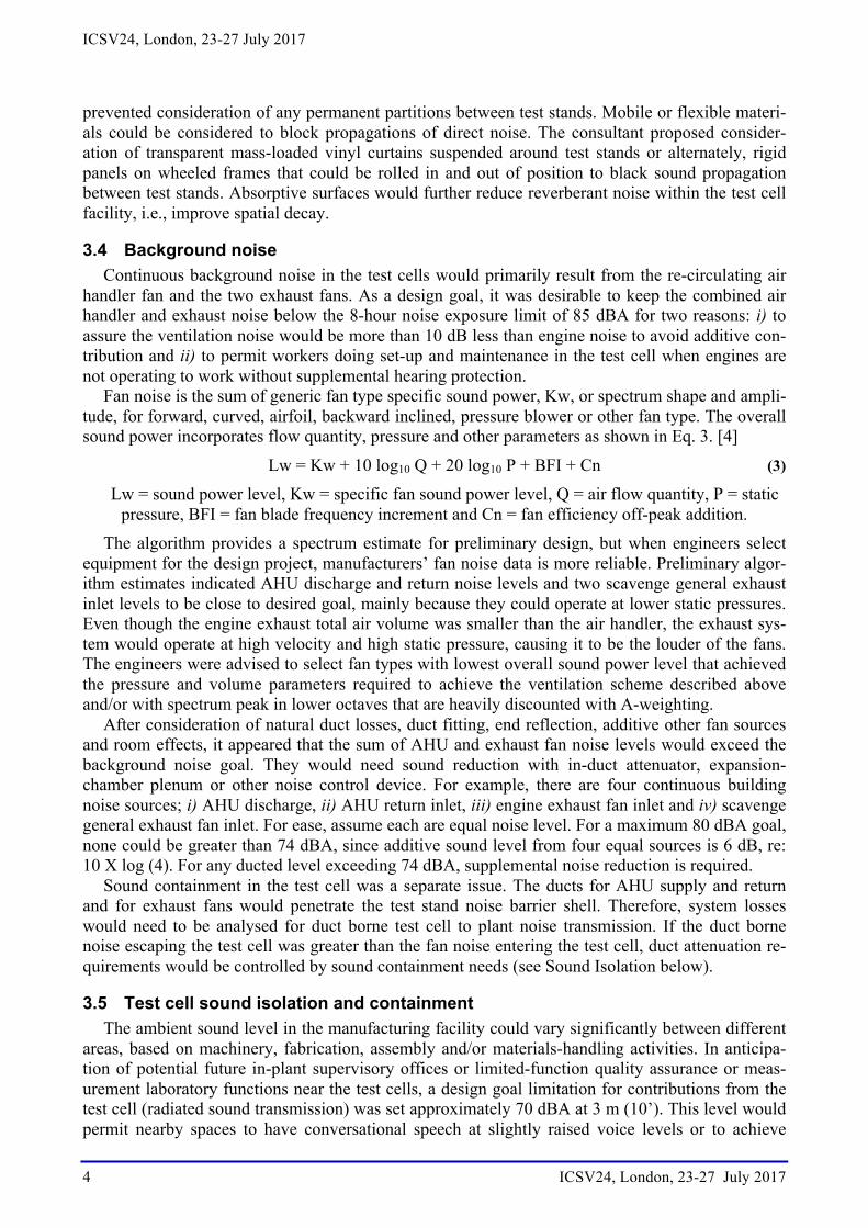
3.4 Background noise Continuous background noise in the test cells would primarily result from the re-circulating air
handler fan and the two exhaust fans. As a design goal, it was desirable to keep the combined air handler and exhaust noise below the 8-hour noise exposure limit of 85 dBA for two reasons: i) to assure the ventilation noise would be more than 10 dB less than engine noise to avoid additive con-tribution and ii) to permit workers doing set-up and maintenance in the test cell when engines are not operating to work without supplemental hearing protection.
Fan noise is the sum of generic fan type specific sound power, Kw, or spectrum shape and ampli-tude, for forward, curved, airfoil, backward inclined, pressure blower or other fan type. The overall sound power incorporates flow quantity, pressure and other parameters as shown in Eq. 3. [4]
Lw = Kw + 10 log10 Q + 20 log10 P + BFI + Cn (3)
Lw = sound power level, Kw = specific fan sound power level, Q = air flow quantity, P = static pressure, BFI = fan blade frequency increment and Cn = fan efficiency off-peak addition.
The algorithm provides a spectrum estimate for preliminary design, but when engineers select equipment for the design project, manufacturers’ fan noise data is more reliable. Preliminary algor-ithm estimates indicated AHU discharge and return noise levels and two scavenge general exhaust inlet levels to be close to desired goal, mainly because they could operate at lower static pressures. Even though the engine exhaust total air volume was smaller than the air handler, the exhaust sys-tem would operate at high velocity and high static pressure, causing it to be the louder of the fans. The engineers were advised to select fan types with lowest overall sound power level that achieved the pressure and volume parameters required to achieve the ventilation scheme described above and/or with spectrum peak in lower octaves that are heavily discounted with A-weighting.
After consideration of natural duct losses, duct fitting, end reflection, additive other fan sources and room effects, it appeared that the sum of AHU and exhaust fan noise levels would exceed the background noise goal. They would need sound reduction with in-duct attenuator, expansion-chamber plenum or other noise control device. For example, there are four continuous building noise sources; i) AHU discharge, ii) AHU return inlet, iii) engine exhaust fan inlet and iv) scavenge general exhaust fan inlet. For ease, assume each are equal noise level. For a maximum 80 dBA goal, none could be greater than 74 dBA, since additive sound level from four equal sources is 6 dB, re: 10 X log (4). For any ducted level exceeding 74 dBA, supplemental noise reduction is required.
Sound containment in the test cell was a separate issue. The ducts for AHU supply and return and for exhaust fans would penetrate the test stand noise barrier shell. Therefore, system losses would need to be analysed for duct borne test cell to plant noise transmission. If the duct borne noise escaping the test cell was greater than the fan noise entering the test cell, duct attenuation re-quirements would be controlled by sound containment needs (see Sound Isolation below).
3.5 Test cell sound isolation and containment The ambient sound level in the manufacturing facility could vary significantly between different
areas, based on machinery, fabrication, assembly and/or materials-handling activities. In anticipa-tion of potential future in-plant supervisory offices or limited-function quality assurance or meas-urement laboratory functions near the test cells, a design goal limitation for contributions from the test cell (radiated sound transmission) was set approximately 70 dBA at 3 m (10’). This level would permit nearby spaces to have conversational speech at slightly raised voice levels or to achieve
ICSV24, London, 23-27 July 2017
ICSV24, London, 23-27 July 2017 5
moderate background noise within simple or lightweight enclosures or rooms. Given the 105 (+) dBA interior level anticipated within the test cells, the shell walls, doors, windows and roof element would need A-weighted sound transmission loss or noise reduction values in excess of 35 dBA.
To maintain a test cell noise containment goal of 70 dBA, the three ventilation sources’ ducts could not permit sound flanking through the shell walls or roof; a) make-up outside air for AHU, b) engine exhaust inlet duct and/or fan discharge and c) scavenge inlet duct and/or fan discharge. After considering 5 dBA for additive sources, re: 10 x log (3), none of the duct breakout radiation levels or fan discharges should exceed 65 dBA Each duct penetration of the test stand roof deck would need attenuation sufficient to attenuate the difference between 65 dBA and interior sound levels exceeding 100 dBA (less small amount of natural duct losses, end reflections, etc.)
Transient noise contributions to the ambient would include test stand engine set-up and other ac-tivity in the room. Although these events are difficult to predict on a quantitative or exposure basis, they are also controllable by the working personnel and supervisors in the facility. Therefore, tran-sient noise was considered in the facility design only for contribution to continuous ambient.
4. Design approach
4.1 Room acoustic conditions The engineering designers inquired of the consultant what building materials could be used for
the test cell walls and roof deck/ceiling. Given the parallel requirements for interior acoustical ab-sorption and noise containment, it was necessary to consider building materials with sound trans-mission class (STC) [5] and noise reduction coefficient (NRC) [6] ratings for sound isola-tion/containment and acoustical absorption, respectively, to design sound isolating wall and roof assemblies with acoustical absorption on the surfaces. Outside North America the ISO Sound Re-duction Index (SRI) is similar to STC. EN ISO 354 [7] is similar to NRC. Note that the NRC is an average of sound absorption coefficients from 250, 500, 1 k and 2 k Hz octaves, which relates to least A-weighted octave sound levels, as illustrated in Fig. 3. Therefore, fairly reliable results are possible without requiring octave or smaller band spectral analysis.
Figure 3: Small gasoline-powered manual tool examples (generic).
Wall materials should have appropriate durability for industrial environments. The sound isolat-ing integrity of the rooms also require noise reducing doors, windows and air duct penetrations.
The consultant recommended consideration of three primary building material categories: • Masonry: Acoustically absorptive slotted concrete masonry units, which are available in
moderate and high transmission loss versions. The sizing and configuration of face slots and the type of inner-cell filler (exposed via slots) control the absorption spectrum and amount.
ICSV24, London, 23-27 July 2017
6 ICSV24, London, 23-27 July 2017
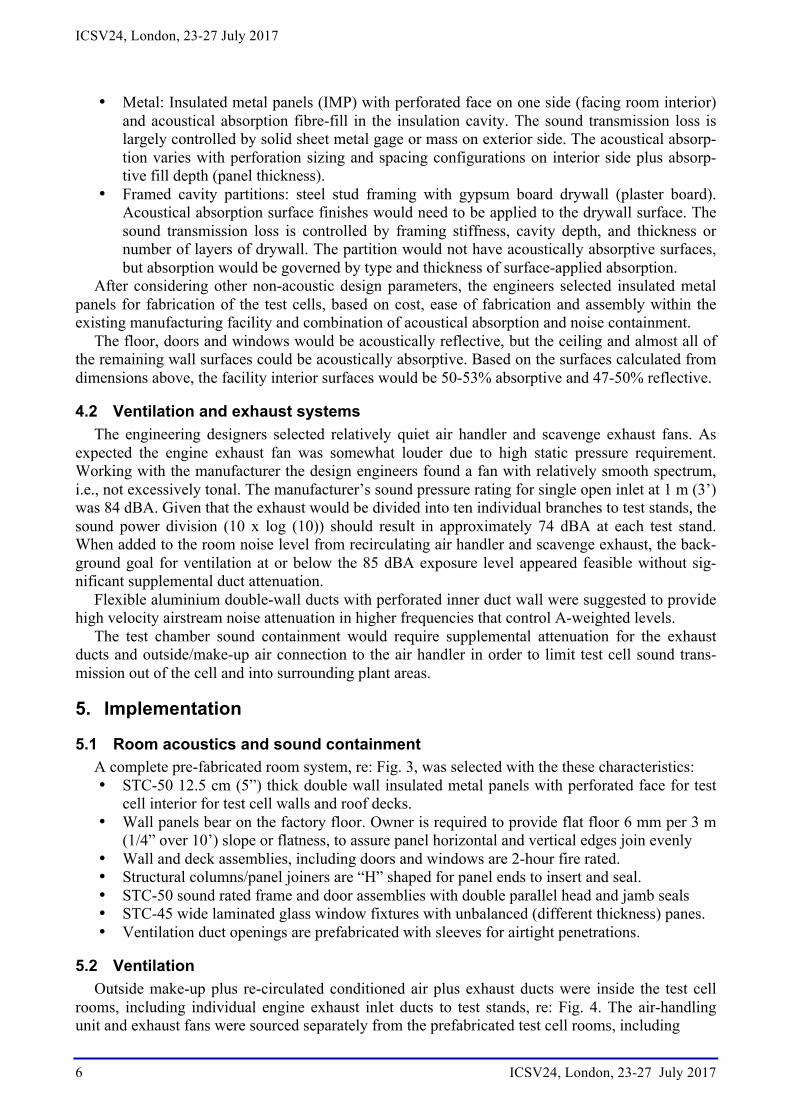
• Metal: Insulated metal panels (IMP) with perforated face on one side (facing room interior) and acoustical absorption fibre-fill in the insulation cavity. The sound transmission loss is largely controlled by solid sheet metal gage or mass on exterior side. The acoustical absorp-tion varies with perforation sizing and spacing configurations on interior side plus absorp-tive fill depth (panel thickness).
• Framed cavity partitions: steel stud framing with gypsum board drywall (plaster board). Acoustical absorption surface finishes would need to be applied to the drywall surface. The sound transmission loss is controlled by framing stiffness, cavity depth, and thickness or number of layers of drywall. The partition would not have acoustically absorptive surfaces, but absorption would be governed by type and thickness of surface-applied absorption.
After considering other non-acoustic design parameters, the engineers selected insulated metal panels for fabrication of the test cells, based on cost, ease of fabrication and assembly within the existing manufacturing facility and combination of acoustical absorption and noise containment.
The floor, doors and windows would be acoustically reflective, but the ceiling and almost all of the remaining wall surfaces could be acoustically absorptive. Based on the surfaces calculated from dimensions above, the facility interior surfaces would be 50-53% absorptive and 47-50% reflective.
4.2 Ventilation and exhaust systems The engineering designers selected relatively quiet air handler and scavenge exhaust fans. As
expected the engine exhaust fan was somewhat louder due to high static pressure requirement. Working with the manufacturer the design engineers found a fan with relatively smooth spectrum, i.e., not excessively tonal. The manufacturer’s sound pressure rating for single open inlet at 1 m (3’) was 84 dBA. Given that the exhaust would be divided into ten individual branches to test stands, the sound power division (10 x log (10)) should result in approximately 74 dBA at each test stand. When added to the room noise level from recirculating air handler and scavenge exhaust, the back-ground goal for ventilation at or below the 85 dBA exposure level appeared feasible without sig-nificant supplemental duct attenuation.
Flexible aluminium double-wall ducts with perforated inner duct wall were suggested to provide high velocity airstream noise attenuation in higher frequencies that control A-weighted levels.
The test chamber sound containment would require supplemental attenuation for the exhaust ducts and outside/make-up air connection to the air handler in order to limit test cell sound trans-mission out of the cell and into surrounding plant areas.
5. Implementation
5.1 Room acoustics and sound containment A complete pre-fabricated room system, re: Fig. 3, was selected with the these characteristics: • STC-50 12.5 cm (5”) thick double wall insulated metal panels with perforated face for test
cell interior for test cell walls and roof decks. • Wall panels bear on the factory floor. Owner is required to provide flat floor 6 mm per 3 m
(1/4” over 10’) slope or flatness, to assure panel horizontal and vertical edges join evenly • Wall and deck assemblies, including doors and windows are 2-hour fire rated. • Structural columns/panel joiners are “H” shaped for panel ends to insert and seal. • STC-50 sound rated frame and door assemblies with double parallel head and jamb seals • STC-45 wide laminated glass window fixtures with unbalanced (different thickness) panes. • Ventilation duct openings are prefabricated with sleeves for airtight penetrations.
5.2 Ventilation Outside make-up plus re-circulated conditioned air plus exhaust ducts were inside the test cell
rooms, including individual engine exhaust inlet ducts to test stands, re: Fig. 4. The air-handling unit and exhaust fans were sourced separately from the prefabricated test cell rooms, including
ICSV24, London, 23-27 July 2017
ICSV24, London, 23-27 July 2017 7
• NYB radial general industrial fan, (variable flow) 1,000 cfm at 7.5” wg, 3548 rpm, 2.2 bhp (1,700 m3/hr at 18.7 mbar or 1876 Pascals)
• Aerovent centrifugal roof exhauster, upblast 1040 cfm at 1.15” wg, 1725 rpm, 037 bhp (1,767 m3/hr at 2.9 mbar or 286 Pascals)
• Carrier 39M12 air handler w forward-curved fan, 6,200 cfm at 3.52” wg, 2658 rpm, 7.7 bhp • (10,534 m3/hr at 8.7 mbar or 877 Pascals)
Figure 4: Test Cell interior with acoustically absorptive surfaces and engine exhaust ducts.
Figure 5: Test Stand set-up to support and exhaust a small gasoline engine tool (adaptable for other tools).
ICSV24, London, 23-27 July 2017
8 ICSV24, London, 23-27 July 2017
5.3 Noise exposure – hearing protection The owners did not consider any noise curtains or mobile sound barriers within the test cell to
be feasible, given minimal free space and need to access to all sides of test stand installations. Facility noise control was achieved with sound containment, interior absorption (increase spatial
decay) and ventilation equipment noise limitations described above. Worker hearing protection was increased by authorizing employees to enhance over-ear noise
reduction headphones with in-ear plugs. It was noted that due to acoustic energy absorbed in jaw bones and similar limiting conditions, the over-ear headphone enhancement with ear plugs is minor.
6. Conclusions
6.1 Design goals satisfied Although we do not have noise measurement results from owner to validate results, our client,
the design engineers report owner satisfaction. The facility is in full time operation, and has not been delayed due to industrial hearing protection issues from excess noise exposure. The combina-tion of reverberant noise control with reduction of background ventilation noise allows for engine noise at the margins of design criteria for allowable noise levels and worker exposure.
6.2 What could have been done differently Should engine noise levels and worker exposure increase due to increase in number of simulta-
neously operated engines or introduction of larger, louder engines, the number of test stands and their configuration could be reduced. This would permit installation of acoustical barrier curtains (which could be moved out of way for engine access) or rolling mobile sound barriers between the engine test stands. Either alternative can reduce reverberant noise addition to direct noise at indi-vidual engine test stands.
Acknowledgments
The author wishes to thank our Client, SGS-CyberMetrix, for permission to publish this case study and for assistance with graphic and photographic documentation. A confidentiality agreement pre-vents identification of owner or location of manufacturing plant.
2 Asselineau, M., Building Acoustics, CRC Press, Taylor & Francis Group, Boca Raton, FL, 18-19 (2015), [Online.] available: https://www.crcpress.com/Building-Acoustics/Asselineau/p/book/
3 Foreman, JEK, Sound Analysis and Noise Control, Van Nostrand Reinhold, New York, NY (1990).
4 ASHRAE. 2007. “Sound and Vibration Control,” Chap. 47, ASHRAE Handbook of HVAC Applications. American Society of Heating Refrigerating and Air-Conditioning Engineers, Inc., Atlanta (2007)
5 Sound Transmission Class, ASTM International Classification E413 and E90. American Society for Test-ing and Materials, West Conshohocken, PA (2016) www.astm.org/Standards.htm
6 Noise Reduction Coefficient, ASTM International Classification C423. American Society for Testing and Materials, West Conshohocken, PA (2016) www.astm.org/Standards.htm
7 Measurement of sound absorption in a reverberation room, ISO 354 : 2003, International Organization for Standardization, Geneva (2003-05) www.iso.org.