NASA Contractor Report 181790 Noise Produced by Turbulent Flow Into a Rotor: Users Manual for Noise Calculation R. K. Amiet, C. G. Egolf, and J. C. Sirnonich United Technologies Research Center East Hartford, CT Contract NAS1-17763 June 1989 National Aeronautics and Space Administration Langley Research Center Hampton, Virginia 23665-5225 NA9-29152 (NASA-CR-181790) NOISt PROOUCEC) RY TURBlJLEYT FLOW INTO A ROTOR: USER5 MAHUAL fOR NOISE CALCULATION Final Report (United Technologies Research Center) 38 p CSCL ZOA uncl as G3/71 0225002 https://ntrs.nasa.gov/search.jsp?R=19890019781 2019-02-11T02:06:01+00:00Z
Transcript
NASA Contractor Report 181790
Noise Produced by Turbulent Flow Into a Rotor: Users Manual for Noise Calculation
R. K. Amiet, C. G. Egolf, and J. C. Sirnonich
United Technologies Research Center East Hartford, CT
Contract NAS1-17763
June 1989
National Aeronautics and Space Administration
Langley Research Center Hampton, Virginia 23665-5225
NA9-29152 (NASA-CR-181790) N O I S t PROOUCEC) R Y TURBlJLEYT FLOW I N T O A ROTOR: USER5 MAHUAL f O R NOISE C A L C U L A T I O N F i n a l Report
(United Technologies Research Center) 38 p CSCL Z O A uncl as
Name Type Description ............................................................. DH
DR H
HOLD IARRAY
I2 IT IP ISTXT JJ K LPOUT NOPIN2
NP IR IT NWRDS P2 P22 PH RARBAY
RCP ECP 1. SUM TH
OUTPUT
Name
RD
RD RD
RD I
I I I I I I I RD
I
I I RD RD RD RD
RD RD RD RD
T 1
Type
Fractional harmonic spacing bet-Jeen frequency calculat ions Increment between radial points Frequency of aound in multiples of blade passage harmonics Last harmonic calculated Array containing integer vords from a data member record Do loop index Do loop index Number of P values Status of calls to data member routines Do loop index Do loop index Logical unit to vrlte Array containing data member name of HOP input file Do loop index Number of radial points Do loop index Humber of vords read in from data mamber record Pressure averaged around azimuth Previous P2 value Angle of flight Mach number Array containing the real vords from a data memb record Radial point Previous radial point Sum of pressure squared contributions to noise Polar angle of observer
Description ............................................................... H RD Frequency of sound in aultiplea of blade
passage harmonic F1 RD Frequency of sound in Hz PSD RD Spectrum level in dB (per unit Hz) NP 1 RD Summation counter IM 1 RD Summation counter N RD Summation counter
FUNCTIONS 1. To call subprogram to read in input values 2. To call subprogram giving spectrum integrated over azimuth 3. To perform integration of spectrum over radlus
SUB3ROGBAMS CALLED LlNCLOS MIGETR MMOPRD NOPIlP PX XFETCH XSTORE
2
* *
t t t * t
t t t
t
t t
* * t t
* * t
* t
t
t
t * * t t
t t*t
CALLING PRQGRA!.IS ANOP EXEC
ERRORS NOH-FATAL
FATAL 1. Error opening data member for input
none
ENTRY Print the input quantities for checking Write tho values of the deformation tensor If beginning harmonic is negative, return to matrix input If harmonic spacing is negative, return to previous input If number of steps is negative, return to first input Calculate frequency step size Print headings for the eventual output Initialize the frequency variable Input of zero for L2 defaults to a single frequency step DO 60 K=l,L2
Increment frequency Initialize radius Initialize 3um DO 22 12=1,19
Increment blade radlal position Calculate tip Mach number at this radius Call subroutine giving azimuthally averaged spectrum at this radiua Halve first value in trapezoidal integral over radius Add to integrated spectrum
END DO Calculate PSD Calculate haraonic Write results
END DO EXIT
3
ROUTINE - MOPINP
~
* * t
* * * * * * * t t
I t
* * * * t * * * t
t t * t t * t
* * t *
t * * t
I * * *
I * I
*
~ *
PURPOSE - To read in input variables and calculate the inean and turbulence properties f o r an atmospheric boundary layer
AUTHOR - J. C. Simonich
INPUT
USER PARAMETERS
Name
A0 D C BH FF EPS HF
N UM TMIH
..........
nL
TMAX DELT
PMIN
PHAX DELP
TY Pe ........ RD RD RD RE) RD RD I I I RD
RD RD
RD
RD ED
Description
Speed of sound (m/s) Diameter of rotor (m) Blade chord (m) Number of blades Distance from rotor to observer (m) Rotational speed in revlsec First harmonic Last harmonic Number of frequency points Minisum observer polar angle in degrees (theta=O along rotor axis in thrust direction) Maximum observer polar angle in degrees Desired increment in polar angle between success calculations Minisum observer azimuthal angle in degrees (phi=O in direction of mean vind) Maximum observer azimuthal angle in degrees Desired increment in azimuthal angle betveen successive calculations
............................................
DATA MEMBER ROTNOP(ABLOT1) - This is the output from the FM ABL
GUS, LWX, WUIHF
Name Type Description
GWS R D Geostrophic vind speed (m/s) LWX RD Correlation length scale WUINF RD Vertical component of the rms turbulence
DATA MEMBER ROTNOP(ROTOT1) - This i3 the output from t h e FM ROT
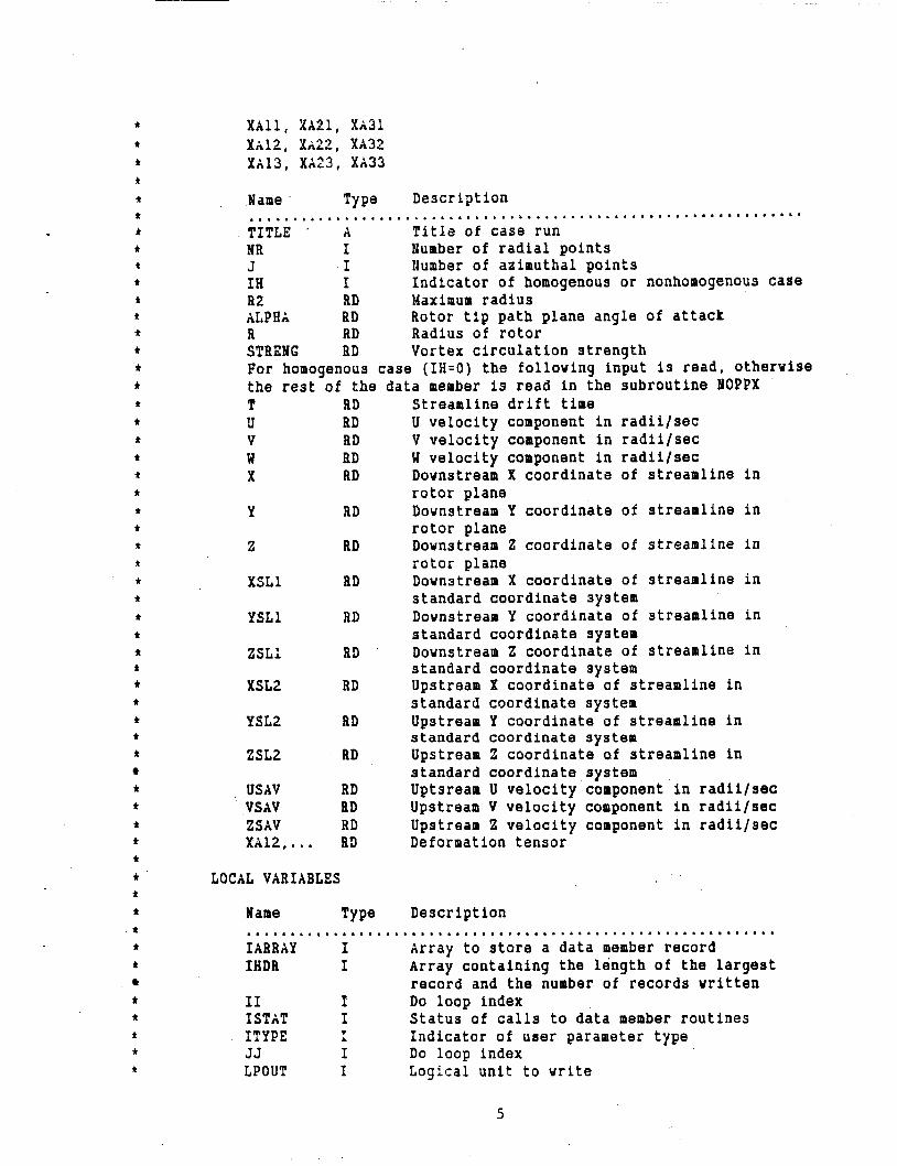
TITLE 118, J, IH R2, ALPHA, R STRENG If IH=O (homogenous case) read in following: T, iT, V, W, X , Y, 2 XSLL, YSLL, ZSLL, XSLZ, YSLZ, ZSLZ USAV, VSAV, USAV
TITLE ’ A Titls of case run NR I lumber of radial points J I lumber of azimuthal points In I Indicator of homogenous or nonhomogenous case R2 RD Maximum radius ALPHA RD Rotor tip path plane angle of attack R RD Radius of rotor STRENG RD Vortex circulation strength For homogenous case (IH=O) the folloving input is read, othervise the rest of the data member is read in the subroutine NOPPX
Streamline drift time U velocity component in radiilsec V velocity component in radiilsec U velocity component in radiilsec Dovnstream X coordinate of streamline in rotor plane Dovnstream Y coordinate of streamline in rotor plane Dovnstrean 2 coordinate of streamline in rotor plane Dovnstream X coordinate of streamline in standard coordinate system Dovnstream Y coordinate of streamline in standard coordinate system Dovnstream 2 coordinate of streamline in standard coordinate system Upstream X coordinate of streamline in standard coordinate system Upstream Y coordinate of streamline in standard coordinate system Upstream 2 coordinate of streamline in standard coordinate system Uptsream U velocity component in radiilsec Upstream V velocity component in radiilsec Upstream 2 velocity component in radiilsec Deformation tensor
LOCAL VARIABLES
Name Type Description
IARRXY I Array to store a data member record IHDE I Array containing the length of the largest
I1 P Do loop index I STAT I Status of calls to data member routines
1. Error finding user parameter in table 2 . Error in opening data member 3 . Error reading in record from data member
FATAL none
ENTRY Input values from data member ROTNOP(NOPIN1) If L ) 0 call STABLE If L ( , O call UNSTAB If L = 0 call NEUTRL Calculate vertical component of the rms turbulence normallzed by the stream velocity Input data member ROTNOP(ROTOT1) If IH=O read in deformation tensor EXIT
6
t
t
t
* * t * * t
* t * * * * t
* * t
f
t
t
t
* f
* t
t
t
t
f
t
* t
t t
t
t
t t
t f
t * t
t t * t
t t
t
t
t
ROUTIIE - MOPPX
PURPOSE - To take the cross product of column vectors N2 and N3 of E and place the result in column N1.
AUTHOR - Roy iZ. Amiet
INPUT
ARGUMENTS
Name Type Description .................................................................. NOPINZ RD Array containing data member name F1 RD Observer frequency RCP RD Radial point TH RD Polar angle of observer PH RD Angle of flight Mach number
COMMON BLOCK
NOPCX
Name
CL BN coc R?C RPS DXDZ 211 FH uu
............ Type Description
RO C3ordjturbulance intagral length scale RD Blade number RD Sound speedlchord RD Far-field diatance/chord RD Revolutions/second RD Deformation tensor RD Axial Mach number RD AD RHS turbulence velocitylaxial velocity
subroutine N I Countsr for rezcaling of CVT i n YTITRB
LOCAL VARIABLES
Name Type Description ................................................................ T M AJ DEL C S C4 S f OM BFZ2 SQ 1 RER SUM G I C2 S 2 cs s5 ALP Cl s1 EM c 3 X Y Z SG FP XK YK T T1 xx YY 22 T2 CVT Z K O AD
RD RD RD RD RD RD RD RD RD ED RD RD RD I RD ED RD RD RD RD RD RD RD ED RD RD RD ED RD RD RD RD RD ED RD RD RD RD RD
SUB P R 0 G A RAM S CALL ED NOPNI XOPLFT
CALLING PROGRAMS NOPMAX
Local tip Mach number Float J Azimuthal step size Cosine theta Sine theta Cosine psi Sine psi Expression in analysis Expression in analysis Expression in analysis Retarded radius/actual radius Sum of azimuthal spectral contributions ~zimuthal angle gamma DO loop counter Cosine gamma Sine gamma Cosine (gamma + psi) Sine (gamma t psi) ingle alpha Cosine alpha Sine alpha Mach number component along chord Cosine of angle phi in analysis Observer coordinate Observer coordinate Observer coordinate Modified radius Frequency measured on blade Value of x vavenumber Value of y vavenumber Blade passage time T h e betveen eddy chops Specific value of x in analysis Specific value of 'J in analysis Specific value of z in analysis Time T1 plus propagation time difference Step size for summation over vavenumber Initial value of vavenumber in summation Contribution to sum of particular aziinuthal station
8
t
t
* t
* t * t * * t
t t
t
t
t
t
t t t * t * * * * t
t
t
t
t t
t
t * t
t t t t
NON -FATAL 1. Error reading in data mamber record
FATAL none
ENTRY Calculate TN, the local tip Hach number Float J Calculate DEL, the azimuthal step size C, S and C4, SA, are the cosine and sine of theta and p s i
OM Is a factor appearing in the analysis BFZ2 is a ?randtl-Glauert factor SQl is a factor appearing in the analysis RER is the observer retarded distance/actual distance Initialize XP1,. ... G DO 50 I=l,J
Increment gamma Find cosine and sine of gamma and gamma + p s i respectively Calculate ALP, the angle of the rotor blade vrt the rotor plane Calculate C1 and S1, the cosine and sine of alpha Calculate RM, the Mach number of rotor segment vrt to fluid Calculate C3, the cosine of an angle in the analysis Calculate observer coordinates in rotor fixed coordinates Calculate sigma, a sodified observer distance
Calculate XK and YK, the x and y vavenumbers Calculate T I the time between blade passes Calculate T1, the time betveen eddy intersection3 Calculate XX, YY, ZZ which are X, Y , Z values Calculate CVT which is 2*Pi/eddy passing distance 2 Calculate ZfO, the Initial radian frequency in the summation Call turbulence summation subroutine Call airfoil response subroutine Incrsment counters Contribution to spectrum from azimuthal integration Summation over azimuthal spectrum
respectlvely
Integration over azimuthal angle gamma
. Calculate FP, the frequancy on the blade
End DO Multiply by remaining factors
EXIT
9
t * *
* t
t
t
t
t
t
t
t
t t
t
t
t
f t
t
t
* * t
t
t
t
t
t
f
t
t
t
t
t
t t
f
t t
t
t
t
t
t
t
t t
t
t
t
t
* * *
ROUTINE - MOPCBS
PURPOSE - To take the cross product of column vectors N2 and N3 of E and place the result in column Hi.
A U T H O R - Roy R . Xmiet
IBPU?
ARGUMENT
Name Type Description
E RD 3x3 rotation matrix. H 1 I Column into which the cross product is to be
ENTRY Calculate N2 and N3 so that N1, N2, N3 are in cyclic permutation. Calculate croaa product of column vectors l2 and N3; place result column N1. Find the magnitude of vector N1. Horsalize vector N1.
EXIT
10
h
f
f
f
f
f
t
f
* t
* t
t
t
t
* * t
* t f
t
t
R
* t
t t
t t
t
t
t
t
t
t
t
t
t t
t
i
* i
t * t
t
t
ROUTINE - H O P R V C
PURPOSE - To calculate effect of rapid distortion on turbulence spectrum .
AUTHOR - Roy K . Amiet
INPUT
ARGUMEHT
llame Type Description .............................................................. DK RD Wavevector DXDZ RD Deformation tensor VH RD Unit vector normal to blade
OUTPUT
XBGUElEHT
Name Type Description .............................................................. ED RD Three coordinats vectors downstream of
E3 RD Three coordinats vectors upstream of
DKN RD Magnitude of downstream vavevector. DKUK ED Ratio of downstream to upstream vavevectors. UQDQ RD Ratio of upstream to dovnstream turbulent
contract ion.
contraction.
velocities.
LOCAL VARIABLES
Name Type Description
F(I) RD For temporary storage of EU(1,J). AF 1 BD Magnitude of wavevector, to be used for
FUNCTIOHS 1. To calculate the effect of rapid distortion on the wavevector and Fourier component amplitude
SUBPROGARAMS CALLED NOPCRS
CXLLIIG PROGRAMS YOPII
ERRORS NONE
n. m ril 3Y Find magnitude of vavevector.
f
f
t
t
* * f
t
t
* t
t
t
f
* * * * f
* f
* i t
DO I = 1,3 S a t thlrd column of ED equal to vavevector direction. Set second column of EL) equal to blade nornai.
E!lD DO Find cross product of first two vectors Find cross product of previocs result vlth third vector of ED. DO I=1,3 DO J=1,3
Initialize EU DO K=1,3
EX3 DO Take product of ED with deformation natrix to find E3.
EID DO END DO Store third column of EU in F. Find the magnitude of f i r s t column of EL'. loraal ize tha first column of EIJ Find the cross-product of columns 1 and 2 of EU. Find cross-product of previious result with third vector of E U . Calculate ratron of dovnstream to upstream wavevector magnitude. Calculate ratio of upstream to downstream turbulent velocities.
BXIT
12
* * * * * I
t
A
t
d
4
f
* * B
*
Q a
n rt
It
t
d
* 9
1'
* * * * * t t
t t
It t
* t
t * * t t
* t t**
HOUTIlIE - HOPFNL
PURPOSE - To calculata the Fresnel integrals C and S. Ref. Abromovitz and Stegun, p 302.
AUTHOR - Roy K. Amiet INTUT
XRGUNENT
Name Type Description ............................................................. X RD Fresnel integral argusent
OU'=?UT
ARGUMENT
Name Type Description ............................................................... E C Fresnel integrals in form C - IS
LOCAL VARIABLES
Nase Type Description
(2 c Intar3ed:ate variabies from Abromovitz and Stegun. ................................................................ - H C To rotate G in complsx plane.
FU B CT I 0 IS 1. To calculate a value f o r the Fresnel integrals
SUBPROGARAMS CALLED None
CALLING PROGRAMS 'IOPLFT
EBTRY Calculate G from Abronovitz and Stegun equations p 302. Calculate H. Calculata E = C - IS following Abromovitz and Stegun.
EXIT
13
t
t
I * f
* t
t
ROUTIBE - tJOPLFT
PURPOSE - To calculate the airfoil gust response function.
AUTSCR - Roy P.. Amiet
ItIPUT
XRGUMEMT
Name Type Decsription
x RD Chordvise distance SG ED Far-field distance modified by Prandtl-Glauert
R!4 RD Chordwise Mach number component XX BD Chordvise vavenum5er YR RD Spanvise wavenumber
GL2 R D Square of effective lift, including ..................................................................
noncompactness
LOCAL VARIABLES
Name Type Description
B2 RD Column vectors for which the cross product is
UM RD Normalizea the output to a magnitude of 1. RMI ED Similarity Mach number for skeved gusts UMI RD Specifies use of lov or high frequency solution. T2 RD Intermediate dummy variable. c:rl RD Magnitude of E. E RD Complex representation of Fresnel integrals;
1. To calculata the airfoil response function for given values of the wavenumbers
SUBPRCGARAMS CALLED NOPFNL
CALLING PROGRAMS HOPPX
ENTRY Calcnlata Prandtl-Glauert factor 32. UM is proportional t o airfoil chord/acaust:c v a v o : e q t L . RMI 13 Graham'~ siailaritjr Hach number for skeved gust;.
14
t
* * t
* t t * t
.p
tjtt
U M I used in fo::uving l i n k for branching tsat. ea38 af ( U M I - . 7 5 ) NES, ZEERC), 305 IEG: Use sodified Saars function ZERO: Use nodified Sears function POS: Use high reduced frequency solution
Call Fresnel Integrals Find absolute value Calculate square of effective lift
End case. EXIT
15
t
I * * * * * t
t
t
* t
* * *
I
I * * t
* * * * f
t
* * * * * * * t
*
* *
* t
* * * t
t
I
I
I
~
ROUTINE - :lC?NI
* *
PURPOSE - To take tha cro33 product of column vectors 12 and !I3 sf E and place the result in column ill
AUTHOR - Roy R. Amiet
INPUT
A R G U M E ?I T
Name Type Description .............................................................. CL RD Chord/turbulence integral length scale CVT RD Step size for sulnmation Over vavenumber XK RD X vavenumber component YK RD Y vavenumber component Z K RD Z vavenumber component ALP RD Angle alpha G RD Gamma DXDZ RD Deformation tensor; 9 components
OUTPUT
A R G W E N T
Name Type Description
SYV RD Pressure averaged around azimuth NP I Counter for upward summation in NTITRB
E K RD Constant in Karaan spectrum DK RD Wavevector; 3 components C 1 RD Cosine alpha SI. RD Sine alpha C2 RD Cosine gamaa S2 RD Sine gamma YH RD Normal to blade BOT AD Expression in analysis DXDZRl RD Intermediate deformation matrix D X D Z A ED Final deformation matrix after rotation CVT 1 AD Dummy fo r CVT E D RD Downstream unit vectors parallel to axes EU RD Upstream unit vectors parallel to axes DKM R3 Wavevector amplitude downstream at rotor face DKUX 23 Ratio of dovnatreaiii t o x J s t r e a a *Jravevector
XKU RD YK'J RD ZKU RD XY BD Dfl BD DEL1 ED A l RD ZKl ED ZK2 RD
Ratlo of upntream to dovnstream velocity amplltudss Upstrean x value of vavevector; initial value Upstream y value of vavevector; initial value Expression in Karman spectrum; initial value Wavevector amplitude dovnstream at rotor face Ratio of dovnstream to upstream vavevector amplitudes Ratio of upstream to dovnstream velocity amplitudes Upstream x value of vavevector Upstream y value of vavevector Upstream z value of vavevector Expression in Karman spectrum Denominator in Karman spectrum Temporary variable for testing end of iteration Float N Value of x vavenumber Value of y vavenumber
SUBPROGARAMS CALLED NOPKVC
CALL I H G PRO G 2Al-i NOPPX
ERRORS IOr(E
E!ITRY Calculate ice vhich equals 0.74683321L equals 0.373417(c/L)/b; Define vavevector in -airfoil fixed coordinate system; x along
Sine and cosine of ang:cs alpha and gamma.' Calculate normal to airfoil in 3ame coordinate aystern a3 for DK. Calculate rotation matrix.
chord direction, the second three give the spanvise direction and the third three give the normal direction.
chord, y along span, and z along normal.
The f i r s t three components give the
DO 50 I=1,3 DO 30 3=1,3
Initialize DXDZRl DO 30 K=l,3
EID DO Calculate DXDZRL
EID DO
DO 70 I=1,3 EIID no
DO 60 3=1,3 Initialize DXDZR DO 91 K=1,3
END DO Calculate DXDZR
END 30 E:ID DO Introduce dummy for CVT
* t
* t
* * t
* t
* * f
t
t
* t
*
t * * t * t
* k
* t
* * * * *
~
Call deformatron program YOFKVC Calculata denominator for xpstream turbulence with kz = 0.
This vi11 be used for comparisonlater i n program. l4ake CVT as large as possible without losing accuracy.
by factors o f ~ V G and test s i z e of DEL:. Initialize sum variable, SVV. Begin summation with minimum but still positive value of ZK after
Initialize counters BP and NU for number of steps up and dovn i n kz. Sum over increasing values of ZK.
Increase
subtracting integer number of CVT values.
Increment upvard summation counter Set third vavevector component Call deformation program NOPKVC Calculate upstream values of three wavevector components Calculate X Y , an intermediate variable Calculate DN, the denominator of the Karman spectrum Add t o summation, SVV Check for excessive summations Increment z vavevector component Chck to 3ee hov large the denominator has become.
End upvard sumnation Sua over decreasing values of ZK.
Increment dovnvard summation counter Decrement z wavevector component Set third wavevector component Call defamation prograa BOPKVC Calculate upstream values of three vavevector components Calculate XY, an interinediate variable Calculate 2t1, the denominator of tha Karman spectrum Add to summation, SVV Check for excessive summations Check to 338 hov large the denominator has Secome.
End downvard summation Hultiply SVV by remaining factors
EXIT
18
AppendiH A: Computer Program f o r Noise Produced by Rot or-Turbulence I n t erac ti on
A computer program implementing the algorithm discussed i n the Theory Manual for Noise Calculation i s given i n the Computer Listings to follow. Computer List ing 1 i s the main executive port ion of the program; i t prompts for inputs and p r i n t s the output. I t also performs the integration over the rotor span.
The inputs to the program, including the symbols used i n the program, are:
Ct BN C8C RC R I C RPS ZM FM
leu IM SUMS P S I
DH AL 1 L2
c/L = chord/turbulence length scale Blade number co/c = sound speedlchord Blade rad iudchord r / c = far- f ie ld distancelchord Revol u tions/sec M, = axial Mach number Flow Mach number i n rotor plane
6 = observer angle w r t z axis; observer i n x,y plane Number of terms in azimuthal summation; N i n equation ( 8 3 ) $ = angle of Mf w r t z axis; Mf i s positive inward as in f igure 1 Frequency step size i n fractions of a harmonic I n i t i a l harmonic number Number of frequency steps
The numerical constant 203.95 occurring i n the expression for PSD i s obtained by introducing equation (82) into equation ( 6 3 ) and mul t ip ly ing by the blade number. This gives
where
Atmospheric pressure Po = 10"0.987 dynes/cm2 and reference pressure P, = 0.0002 dynes/cm*. Spp must be mult ip l ied by 417 to convert f rom a two sided - co < o < co to a one sided 0 < o < Q)
spectrum and to convert to a un i t Hertz rather than a uni t radian frequency of measurement. Using the relations
E, = ob/Ub co2 = YP,/po (A2 1
th is can be wr i t t en (where y = 2nn /N)
19
I Converting to dB,
2
101Ogl@ [+ ( Y n P o p r ) ] =203.95 The outputs of the program are:
H F 1 P SD NP 1,NM l ,N
Frequency of sound expressed i n mul t ip le o f blade passage harmonic Frequency of sound i n Hz Spectrum level i n dB (per un i t Hz) Counters for certain of the summations for use i n diagnosis of output
The programs i n the following appendices are standard Fortran code w i th added l ine numbers for reference i n the documentation. This allows more detailed comments to be used without deleteriously affecting the ab i l i t y to easily read the code.
The program l i s t ing here i s for an homogenous turbulence i n the r o t o r plane. This can be eas i l y extended to the nonisotropic case by inputt ing the deformation tensor a t each point of the rotor plane rather than just once. The turbulence spectrum at each point of the rotor plane i s then calculated from a rap id contraction of an isotropic turbulence using th is deformation tensor. The changes t o the main program and one subroutine for th is generalization to the nonhomogeneous case are l isted below.
Changes to main program:
12 1 'RADIUS/C, FAR-FIELD/C, RPS, I"/) 24 IF (IH .EO. 8 ) READ(l,+) ((DXDZ(I,J), I=1,3), J=1,3) 25 IF (IH .EQ..B) WRITE(*,2BB) ((DXDZ(I,J), J=1,3), I=1,3) 26 IF (IH .EQ. B ) WRITE(2,2BB) ((DXDZ(I,J), J=1,3), I=1,3) 28 59 1
IF (IH .EQ. 8 ) CLOSE(1) P2,NPl,NMl,M,IH)
In the subroutine SPX, change the f i r s t l i ne of the subroutine to accept the new variable I H and add the following l ine between l ines 46 and 47:
In the above code the parameter IH i s an input designating whether a homogeneous or inhomogeneous calculation should be performed. I f IH = 0 i s input, homogeneous turbulence i s assumed. I f I H = 1 is input, inhomogeneous turbulence i s assumed, and the above read and w r i t e statements a r e deferred to the subroutine SPX.
P X F I N I 1 2 / 3 / 8 4 R . K . Amiet Integrates over spon. DIMENSION D X D 2 ( 3 , 3 ) CHARACTER*10 FNAME CHARACTER"10 FNAMEl WRITE(+ ,500) FORMAT(' Turbulence ingestion program with integration over'
W R I T E ( ' , ' ( A \ ) ' ) ' OUTPUT F I L E NAME - '
R E A D ( * , ' ( A ) ' ) FNAMEl OPEN(2,FILE=FNAMEl,STATUS='NEW') WRITE( * ,100 ) FORMAT( / / ' INPUT C/L, BLADE NO., C0/C, '
READ(* ,+) CL, BN, C B C , RC, R l C , RPS T M 1 = 2.+3.141593*RPS'RC/C0C WRITE( * ,300 ) TM1, CL, BN, C B C , R C , R l C , RPS W R I T E ( 2 , 3 0 0 ) TM1, CL, BN, CBC, RC, R l C , RPS FORMAT( / / ' M T I P = ' , F 4 . 3 , ' CHORD/TURB SCALE = ' , F 7 . 4 /
' BLADE NO. = ' , F 4 . 0 , ' SOUND SPEED/CHORD = ' , F 7 . 1 / ' RADIUS/CHORD = ' , F 5 . 1 , ' FAR-FIELD/CHORD = ' , F 6 . 1 / ' REV/SEC = ' , F S . l / )
* span'/' ond nonisotropic turbulence. R . K . Amiet 1 2 / 8 4 ' / )
'RADIUS/C, FAR-FIELD/C, RPS ' / ' )
W R I T E ( * , ' ( A \ ) ' ) ' INPUT F I L E NAME - '
R E A D ( * , ' ( A ) ' ) FNAME OPEN(l,FILE=FNAME,STATUS='OLD') R E A D ( l , * ) ( ( D X D Z ( I , J ) , 1 = 1 , 3 ) , J=1,3) WRITE( * ,200 ) ( ( D X D Z ( I , J ) , J = 1 , 3 ) , I = 1 , 3 ) W R I T E ( 2 , 2 0 0 ) ( ( D X D Z ( I , J ) , J = 1 , 3 ) , I = 1 , 3 ) FORMAT( lX ,3F5 .2 ) CLOSE ( 1 1 WRITE(+ ,400) FORMAT(/ ' INPUT Mi!, FM, UU, THETA, SUMS, P H I ' / ) READ(* ,+) ZM, FM, UU, TH, J, PH WRITE(" ,900) ZM, UU, TH, FM, J, PH WRITE(2 ,900) ZM, UU, TH, FM, J , PH FORMAT(' MZ = ' , F 4 . 3 , ' UU = ' , F 6 . 3 , ' THETA = ' , F 5 . 0 /
WRITE( * ,700 ) FORMAT(/ ' I N P U T ' /
' MF = ' , F 4 . 3 , ' SUMS = ' , I 4 , ' P S I = ' , F 5 . 1 / 1
BEGINNING HARMONIC: I f 0 , go to matrix input.'/ FRACTIONAL HARMONIC SPACING: I f < 0 , go to previous input.'/ NUMBER STEPS: I f < 0 , go to first input.'/)
READ(* ,+) AL1, OH, L2 I F (AL1 . L T . 0 . 1 GO TO 10 I F (OH . L T . 0 . ) GO TO 2 0 I F ( L 2 . L T . 0 ) GO TO 3 0 OF = RPS'BN'DH WRITE( * ,800 ) WRITE(2 ,8001 FORMAT( /2X , 'HRMNC' .SX, 'FREQ' ,6X , 'PSD ' ,4X , 'SM P ' , l X , ' S M M ' / ) F 1 = ( A L l / D H - l . ) * D F I F (L2 .EQ. 0 ) L 2 = 1
Computer L ist ing 1: Executive program for turbulence ingestion.
DO 6 0 K = l , L 2 F 1 = F 1 + OF RCP = RC'1.05 SUM = B . DO 22 I 2 = 0 , 1 9 RCP = RCP - .05*RC TM = TMl*RCP/RC CALL PX(F l ,ZM,CL,BN,CBC,UU,RCP,RlC,RPS,FM,TH,J ,PH,DXD~,
P 2 , N P l , N M l , N ) I F ( 1 2 .EO. a ) ~2 = ~ 2 1 2 . SUM = SUM + P 2 CONTINUE PSD = 10.*ALOG10(SUM*RC*.05) H = F l / ( R P S * B N ) W R I T E ( * , 6 0 @ ) H, F1, PSD, NP1, NM1, N W R I T E ( 2 , 6 0 8 ) H, F1 , PSD, NP1, NM1, N FORMAT(lX,F6.1,1X,F8.l,lX,F9.2,lX,I5,216) CONT I NUE
END GO T O 7 0
Comment Prompt for a filename into which to w r i t e the calculated resul ts Prompts f o r inputs Calculation of t i p Mach number P r i n t s the input quantities for checking Prompt for input containing the deformation tensor values Read and w r i t e the values for the deformation tensor Prompt for more input parameters; wr i tes out values to f i l e Prompt for f inal input values; i f any are negative the program re tu rns to one of the previous input prompts DF = frequency step size P r i n t s headings for the eventual pr in tout In i t ia l ize the frequency variable Input o f zero for L2 gives one i terat ion w i t h th is l i ne Stepping through frequency range Increment frequency variable In i t ia l ize radius and summation variables Integration over rad i us RCP = local radius TM = Mt local t i p Mach number C a l l routine for summation over Y Divide the f i r s t term in the summation by 2; the last term also should halved, but since i t approaches zero, i t needn't be expl ic i t ly set to zero. Perform radial summation Introduce remaining factors i n equation ( 6 9 ) Calculate harmonic number W r i t e outputs
Computer L i s t i ng 1: Executive program fo r turbulence ingestion.
, 22
Appendix B: Subroutine Calculating the Main Problem Parameters and Integrating ouer Azimuth
This subroutine is called by the main turbulence ingestion program in Appendix A. It calculates geometry and integrates over azimuthal angle. The inputs to the subroutine are:
F1 ZM
BN coc uu FZ: R1 C RPS FM M J PSI DXDZ
a Observer frequency Axial Mach number; see figure 1 Chordhurbulence integral length scale Blade number . Sound speed/chord RMS turbulence intensity/axial velocity Local blade radiuskhord Far-fie Id distancekho rd Revolutions per second Flight Mach number in rotor plane; see figure 1 Polar angle of observer; see figure 1 Number of azimuthal integration points Angle of flight Mach number with the y axis; see figure 1 Deformation tensor
The outputs are:
P2 NP1 ,NM1 ,N
Sound level from a radial blade segment Counters used in the summations: used for diagnostic purposes
The program calls the subroutines TRBNl and LEFF, the turbulence and the airfoil response calculations. The subroutine performs the azimuthal integration over 0 in Eq. (63).
Subroutine SPX P r o g r a m written by R . K . Amiet. SUBROUTINE PX (F 1 , ZM, CL ,BN ,C0C ,UU ,RC ,R 1C ,RPS ,FM, TH, J , P S I ,DXDZ,
DIMENSION D X D Z ( 3 , 3 ) P I = 3 . 1 4 1 5 9 TM = 2."PI*RPS"RC/CBC AJ = J DEL = 3 6 0 . / A J C = C O S ( T H / 5 7 . 2 9 5 8 ) S = S I N ( T H / 5 7 . 2 9 5 8 ) C4 = C O S ( P S I / 5 7 . 2 9 5 8 ) S 4 = S I N ( P S I / 5 7 . 2 9 5 8 ) QM = FM*S+S4+ZM+C
SQ1 = SQRT(QM**2+BFZ21 R E R = (SQl+QM)/BFZ2 NP1 = 0 NM1 = B SUM = 0 . G = 9 0 . - DEL DO 5 0 I = l , J G = G + DEL C2 = C O S ( G / 5 7 . 2 9 5 8 ) S2 = S I N ( G / 5 7 . 2 9 5 8 ) C5 = C O S ( ( G + P S I ) / 5 7 . 2 9 5 8 ) S5 = S I N ( ( G + P S I ) / 5 7 . 2 9 5 8 ) ALP = 57.2958+ATAN2(ZM,TM+FM+C5) C 1 = C O S ( A L P / 5 7 . 2 9 5 8 ) S 1 = S I N ( A L P / 5 7 . 2 9 5 8 ) RM = SQRT(ZM""2 + (TM + FM+C5)**2) c3 = C'S1 - S'Cl'S2 X = RlC"(TM"RER"C1 - C3) Y = RlC"(S'C2 + FM"RER"S5) Z = RlC"(C'C1 + S"Sl"S2 + TM'RER'Sl) SG = SQRT(X**2,+(1.-RM*'2)*~Y**2+Z++2)) FP = Fl*(l.+TM*(S2"S-FM"RER*C5)/SQl~ XK = PI*FP/(CBC*RM) YK = PI+FP+Y/(SG*C0C) T = 2.*PI*RC/(TM+C0C'BN) T 1 = T*TM*Sl*Cl /ZM
1 P 2 , N P l , N M l , N )
BFZ2 = l.-FM*+2-ZM*"2
Next line added to make peaks occur a t bpf when ZM = 0 . T 1 = T / ( l . + MF*C5/TM) XX = T M * ( T - T l ) Y Y = Tl'FM'S5 Z Z = T*TM"CBC*Sl
CVT = P I / Z Z ZK0 = P I * T 2 * F l / Z Z CALL TRBNI(CL,CVT,XK,YK,ZK0,ALP,G,DXDZ,SVV,NP,NM,N)
T2 = T 1 + XX"(RM-X/SG) / ( l . - RM'"2) + YY+Y/SG
Computer L ist ing 2: Subroutine for calculating p r i n c i p l e parameters i n problem
P2 = 2.48E20*SUM*BN' (UU*ZM)++2/ (C0C*A~~ RETURN END
Comment Inputs TM = Mt = local t ip Mach number Float J DEL = azimuthal step size C, S and C4, S4 = cosine and sine of 8 and # respectively OM = M, cos 0; Eq. (43 BF22 = 1 - MS2; Eq. (43) SO1 = ( 1 - MS2 sin2 @ ) ' I 2
RER = re/r; Eq. (42 I n i t i a1 i ze variables Integration over azimuthal angle 7 Increment 7 C2, S2 and C5, SS = cosine and sine of 7 and y + Ip respectively ALP = a; Eq. (34 ) C1, S1 = cosine and sine of a RM = Mb; Eq. (36 ) C3 = cos*; Eq. (49) X, Y, Z = ~ 3 , y3, 23; Eq= (48 SG = Q FP = frequency on blade; Eq. (55 XK, YK = specific wavenumbers I?,, Ry; Eqs. (91, ( 14) T = t ime between blade passes T1 = t ime between eddy intersections; Eq. (62 ) for l i ne 39. Equation (32 ) is not appropriate for eddies stretched in axial direction; for th is case the diagonal distance i n f igure 3 i s not appropriate; given here i s the resul t for an eddy of in f in i te axial length corresponding to the l i m i t M,+ 0; Eq. (62). XX, YY, Z t = X, Y, Z i n Eqs. (621, (64 ) CVT = 2n/Z = step size i n Eq. (70 Z K O = ooT2/2 = in i t i a l radian frequency i n Eq. (70 )
C a l l turbulence summation subroutine Ca l l a i r f o i l response subroutine Increment counters Contr ibution to spectrum from azimuthal integration; Eqs, (50 ) and ( 6 9 ) Summation over azimuthal spectrum Mult ip l icat ion by remaining factors i n Eq. (69)
T2 = T2; Eq. (65)
Computer L i s t fng 2: Subrout ine for calculat ing p r i n c i p l e parameters i n problem
25
AppendiH C: Subroutine f o r Summing ouer the Turbulence Spectrum f o r Blade t o Blade Correlation
This subroutine calculates the summation i n Eq. ( 6 9 ) over the turbulence spectrum. The output SVV o f t h i s program i s
svv
The inputs to the
CL = c/L XK = K,
program and the equivalent symbols used i n the repo r t are
CVT = 2nb /Z YK = K y
( E l )
Z K O = a O T Z / t DXDZ(1,J) = i3xi/i3(, ( x i = precontraction coordinate; t j = post contraction coordinate)
Other parameters i n the program are: EK = k,b where k, i s given i n Eq. (32). CVT i s the step size i n the summation. Since the spectrum i s wr i t t en i n a fo rm w i th the wavenumbers k, and k y normalized by k,, CVT must also be so normalized. Note that t h i s changes CVT i n the main program, but t h i s i s o f
no concern since CVT i s used only i n th i s subroutine.
The summation over n i s over the range *a. I n numer ica l ly c a r r y i n g out t h i s summation i t i s easiest to begin where the individual te rms are maximum and sum to e i ther side o f t h i s po int u n t i l the te rms become negligible. Thus, the integer N i s the optimum value of n at which t o begin the summation. The optimum value would be n = 0 except for the offset o o T 2 / Z occur r ing i n KZ( " ) (see
Eq. ( 6 9 1).
I f the step size CVT i s too small , v e r y many te rms i n the summation would be required. F o r th is case, the summation can be replaced by an integral. F o r the case of an isot rop ic turbulence the integral can be car r ied out i n closed f o r m as i n Eq. ( 3 1).
The parameters ZK 1 and ZK2 represent K,(')/ k,. ZK 1 i s used fo r increasing values of n and
1 ZK2 for decreasing values.
The integers NP and NM count the number o f summation steps i n the upward and downward direct ions respectively. I f either goes over 1 0 0 the summation i s terminated, although th is case has never been encountered. I f the output specifies that NP o r NM reached the value o f 100, f u r t h e r checking should be done t o ensure that a suf f ic ient number o f steps were taken. Generally the summation i s terminated when the te rm DN (denoting the denominator i n Eq. ( 3 2 ) ) becomes greater than 200 times the i n i t i a l value of the denominator.
Final ly, the coefficient 0.1 1561 = 55 r(5/6)/[9$.rrI'( 1/31 4nl. The factor 4n comes f rom Eq. (30 ) and the remain ing factors come f rom the expression f o r I.
* EO0YNI.FTN; Summation over turbulence spectrum. Written by R . K. Amiet; final version 1985 SUBROUTINE TRBNI(CL,CVT,XK,YK,ZK,ALP,G,DXOZ,SVV,NP,NM,N) DIMENSION EU(3,3), ED(3,3), VN(31, DK(31, DXDZ(3,3),'
I F (N .GT. 1) C V T l = 2 . * C V T l D K ( 3 ) = C V T l CALL KVEC(DK,DXDZR,VN,ED,EU,DKMl,DKUKl,UQDQl) XKU = EU(1,3) 'DKMl/DKUKl YKU = EU(2 ,3) 'DKMl /DKUKl ZKU = EU(3 ,3 ) *DKMl /DKUKl X Y = EK*+2 + XKU"2 + YKU+*2 DN = ( X Y + ZKU**2)"2.83333 DEL1 = A B S ( 1 . - DN/DB) I F (DEL1 . L T . . e l ) GO T O 18
N = ZK/CVT AN = N ZK1 = ZK - AN+CVT ZK2 = ZK1
NM = 0
D K ( 3 ) = ZK1 CALL KVEC(DK,DXDZR,VN,ED,EU,DKM,DKUK,UQDQ) XKU = EU(l ,S)*DKM/DKUK YKU = EU(2,3)*DKM/DKUK ZKU = EU(3,3)*DKM/DKUK XY = EK"2 + XKU"2 + YKU"2 DN = ( X Y + ZKU**2 ) * *2 .83333 SVV = SVV + (XY - EK+'2)/(UQDQ"2+DN) I F (NP .GT. 1 0 0 ) GO TO 40 Z K 1 = ZK1 + CVT I F (ON . L T . 0 0 * 2 0 0 . ) GO TO 2 0
I F (ON .LT . 0 0 * 2 8 0 . ) GO TO 40 80 SVV = .11561*SVV+CVT*EK**.666667
RETURN END
IF (NM .GT. l e e ) GO TO a0
~
Computer Llstlng 3: Subroutine for calculating summation over turbulence spectrum.
28
. '
l l n e l 1 4 5-7
8-11 12-14 15-23
24-39
40-45
46-58
59 68-63
64-65 66-77
78-89 90
fanmm Inputs k, = 0.74683421L = 0.373417(c/L)/b; 0.7468342 = I ' (5/6)f i / I ' ( 1/31. Define wavevector k i n coordinate system f ixed to air fo i l ; x along chord, y along span, and z along normal. k, w i l l take different values. Sine and cosine of angles a and Y. Normal to a i r f o i l i n same coordinate system as i n l ines 5-7. Rotation matr ix; dzi/dx3 with the definitions i n Eq.( 47). The f i r s t three components give the chord direction, the second three give the spanwise direction and the t h i r d three give the normal direction. 2 1 VN( 1) wr i t ten i n the unrotatedgl system. 22 VN( 2 ) wri t ten i n the unrotated gl system. 23 VN( 3 ) wri t ten i n the unrotatedgl system. Calculate deformation tensor i n coordinate system defined i n l ines 5-7. F i r s t premult iply, then postmultiply, DXDZ by ROT. Denominator f o r upstream turbulence wi th k, = 0. Used for comparison i n lines 77 and 89. If CVT i s too small, w i l l take too many summations. Make CVT larger unt i l s tar t getting significant variat ion i n either the rat io of wavevectors between downstream and upstream. In i t ia l ize sum variable. Begin w i th minimum but s t i l l positive value after subtracting integer number of CVT values. In i t ia l ize counters for number of steps up and down in k, Sum over increasing values of k,. Lines 69-7 1 calculate upstream values of wavevector. These expressions are placed into isotropic turbulence i n 72-83. Line 75: check on number of iterations. Line 76: increment k,. Line 77: check to see how large the denominator has become. Same comments as l ines 53-64 except summation is in downward direction. Factors mul t ip ly sum. Note that CVT i s included in the product so that i t i s o'k to increase CVT i n l ines 46-58 making the summation step size bigger. 0.1 1561 = s s r ( s m / [ 3 6 ~ ~ 3 / * r ( 11311
Computer Lfttfng 3: Subroutine for cslculatlng summation over turbulence spectrum.
29
AppendiH 0: Program for Calculating Airfoil Response Function, L, for leading Edge Noise
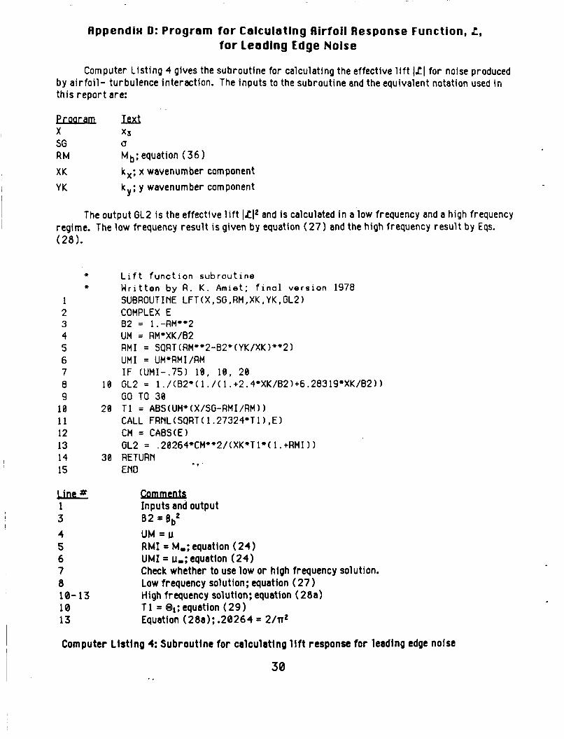
Computer Listing 4 gives the subroutine for calculating the effective l i f t ILl f o r noise produced by a i r fo i l - turbulence interaction. The inputs to the subroutine and the equivalent notation used i n this report are:
Proaramm X x3 SG U
RM Mbiequation (36) XK kx; x wavenumber component
k ; y wavenumber component YK Y
The output GL2 i s the effective l i f t lLI2 and is calculated i n a low frequency and a high frequency regime. The low frequency result i s given by equation ( 2 7 ) and the high frequency result by Eqs. (28).
* Lift function subroutine * Written by R . K. Amiet; final version 1978
1 SUBROUTINE LFT(X,SG,RM,XK,YK,GL2) 2 COMPLEX E
4 UM = RM*XK/B2 5 RMI = SQRT(RM**2-B2*(YK/XK)+'2) 6 UMI = UM*RMI/RM 7 IF (UMI-.75) 10, 10, 20 8 10 GL2 = l./(B2*(1./(1.+2.4+XK/B2)+6.28319*XK/B2)) 9 GO TO 30
3 82 = l .-RM"2
le 20 T1 = ABS(UM+(X/SG-RMI/RM)) 1 1 CALL FRNL(SQRT(1.27324+Tl),E) 12 CM = CABS(E1 13 GL2 = .28264*CM**2/(XK*Tl*(l.+RMI)) 14 30 RETURN 15 END * *
ule 1 3 4 5 6 7 8 10-13 10 13
ciunnmh Inputs and output
UM = u RMI = M,; equation (24) UMI = u-; equation (24) Check whether to use low o r high frequency solution. Low frequency solution; equation (27 High frequency solution; equation (28a) T 1 = Oi; equation ( 2 9 Equation (28a); .20264 = 2/n2
8 2 = t3b2
Computer L is t ing 4: Subroutine for calculating l i f t response fo r leading edge noise
tlppendix E: Program for Calculating the Effect o f Contraction on the Turbulence Spectrum
Computer List ing 5 gives the subroutine for calculating the effect of a contraction of a turbulence spectrum. This subroutine has as input a 3 x 3 deformation ma t r i x representing a flow contraction. The program then accepts a flow direction &, and a wavevector k both for the downstream flow, and calculates the.upstream Wavevector and flow vector. The inputs to the subroutine and the equivalent notation used i n th is repor t are:
Proaramm DK DXDZ VN ED, EU
- kd = downstream wavevector components dxi/dtj = deformation tensor; equation (71 1 Upwash velocity component normal to the a i r f o i l Tensors representing the three vector components of the upstream and downstream coordinate systems. Each such vector i s represented by a column of the matrix.
1 2 3 4 5 6 7
9
1 1 12 13 14 1s 16 17 18 19 20 21 22 23 24 2s
a
ie
The outputs are:
* *
ie
38 20
68 50 48
Wavevector amplitude downstream at the rotor face Ratio of downstream to upstream wavevector amplitudes Ratio of upstream to downstream velocity amplitudes
Turbulence contraction calculation. Written by R. K. Amiet 9/7/83 SUBROUTINE KVEC(DK,DXDZ,VN,ED,EU,DKM,DKUK,UODO) DIMENSION E0(3,3). EU(3,3), VN(31, F3(3), OK(31, OXOZ(3.3) DKM = SORT(OK(1)**2 + OK(2)**2 + OK(3)*+2)
DO 28 1=i,3 00 38 ~ = i , 3 EU(1,J) = e . * * CONT I NUE CONT I NUE
DO 50 J=1,3 DO 68 K=1,3 EU(1,J) = EU(1,J) + DXDZ(K,I)*ED(K,J) CONT I NUE CONT I NUE CONT I NU€ F3(1) = EU(1,3) F3(2) = EU(2,3) F3(31 = EU(3,3) AF1 = SQRT(EU(1,1)**2 + EU(2,1)**2 + EU(3,1)**2)
DO 48 1=1,3
Computer Listing 5: Subroutine for calculating effect of contractlon on turbulence spectr um
31
26 27 28 29 30 31 32 33 34
3 4- 7 8
9
1 0 - 1 4 15-21
22-24
25 26-28 29 30 31
E U ( 1 , l ) = E U ( l , l ) / A F l E U ( 2 , l ) = E U ( 2 , 1 ) / A F l EU(3,l) = E U ( 3 , 1 ) / A F 1 CALL CROSS(EU,3) CALL CROSS(EU,2) OKUK = E U ( 1 , 3 ) * F 3 ( 1 ) + E U ( 2 , 3 ) * F 3 ( 2 ) + E U ( 3 , 3 ) * F 3 ( 3 ) UQDO = AFI'DKUK RETURN END
Camments Calculates the magnitude of the downstream wavevector kd. Reads yn into the 2'nd column of ed and a uni t vector along kd into the 3'rd column. Calculates the direction of the vor t ic i ty determined by the specified wavevector k and velocity Vn directions. Calculates the direction of the velocity produced by the wavevector. !In i s a component of
th is velocity. In i t ia l ize matr ix eu. Calculates the values of eu f rom the downstream values ed by using equation( 7 1 ) on each of the 3 column vectors making up ed. This i s not the f inal form for eu. The vector GIu representing the vor t ic i ty direction w i l l keep i t s direction but be normalized to a un i t vector. GSu w i l l be found by taking the cross product of vectors 1 and 2, and G Z u i s then determined b y taking the cross product of G S u and GIu. - F represents a vector found by taking a un i t vector alongkd and transforming according to equation(6 1 lb ) . This i s used to determine kd/ku using equation(72). The magnitude of the transformed value of the vort ic i ty, needed i n equation(73). Uni t vector in the direction of the upstream vort ici ty. Determines the un i t vector i s u f rom the cross product of ilu and&". Determines the uni t vector Determines kd/ku using equation( 72).
f rom the cross product of and diu.
Computer Listing 5: Subroutine for calculating effect of contraction on turbulence spectrum ~
I v '
32
AppendiH F: Subroutine for Calculating the Cross Product o f Two Uectors
Computer Listing 6 gives the subroutine f o r calculating the cross product o f two vectors. The subroutine takes a 3x3 matrix E( i , j ) composed of 3 column vectors ii and replaces the Nl'th vector by the normalized cross product of the other two in proper cyc l i c order.The inputs to the subroutine and the equivalent notation used i n this r e p o r t are:
Proaramm E M ) N 1
Tensor with columns composed of vectors: also represents the output Column not involved i n the cross product
b
* +
1 2 3
5 6 ' I
t3 3 10 11 12 13 14 15
4
Subroutine for calculating cross product of two vectors Written by R . K . Amiet 9/1/83 SUBROUTINE CROSS(E,Nll DIMENSION E ( 3 , 3 ) N2 = N1 + 1 N3 = N1 + 2 I F (N2 .GT. 3) N2 = N2 - 3 I F (N3 .GT. 3) N3 = N3 - 3 E ( 1 , N l ) = E(2,N2)+E(3,N3) - E(3 ,N2 l *E(2 ,N3) E ( 2 , N l ) = E ( 3 , N 2 l * E ( l , N 3 ) - E( l ,N2)*E(3 ,N3) E ( 3 , N l ) = E ( l , N 2 ) * E ( 2 , N 3 ) - E ( 2 , N 2 ) * E ( l , N 3 ) ENlM = SQRT(E(l ,N1)+*2 + E(2,N1)**2 + E(3 ,N1)+*2) E ( 1 , N l ) = E ( l . N l ) / E N l M E ( 2 , N l ) = E ( 2 , N l ) / E N l M E ( 3 , N l ) = E ( 3 , N l ) / E N l M RETURN END
W f h u M u 2-6
7-9 10- 13
Defines the cyclic sequence 1,2,3 or 2,3,1 o r 3,1,2 where N 1 i s the first number o f the sequence. Replaces the N l ' th vector by the cross product of the other two. Normalizes the Nl'!h vector t o have a magnitude o f 1.
Computer List ing 6: Subroutine for calculating cross product o f two vectors
33
Appendix G: Subroutine for Calculating the Fresnel Integral
Computer L is t ing 7 gives the subroutine for calculating the Fresnel integrals. The program uses the a lgor i thm given by equations 7.3.9, 7.3.32, 7.3.33 o f Abromowitz and Stegun, Handbook of Mathematical Functions, Dover Publications, New York, 1968.
1 2 3 4 1 5 6 7 8
FRNL.FOR Subroutine f o r calculation o f Fresnel integrols Written by R . K . Amiet 1976 SUBROUTINE FRNL(X,E) COMPLEX E , G, H G = CMPLX((1.+.926*X)/(2.+ 1.792"X + 3 .1@4*X**2) ,
H = CMPLX(SIN(1.5708*X**2~,COS(l.57~8*X**2)) E = G*H + CMPLX(.5,-.5) RETURN END
Computer L i s t i n g 7: Subrou t ine for ca lcu la t ing the Fresnel integrals.
34
.
Appendix H: Sample Calculation
These t w o test cases use the same inputs, l i s t e d below. The on ly d i f ference between t h e cases i s t he deformat ion tensor. F o r the f i r s t case t h e tensor rep resen ts no deformation. The second rep resen ts a deformat ion b y a factor o f 4 i n the ax ia l d i rect ion.