+ All Categories
Home > Documents > Nokia Service Router Linux

Nokia Service Router Linux

Date post: 02-Apr-2022
Category:
Upload: others
View: 14 times
Download: 0 times
Share this document with a friend
140
© 2021 Nokia. Use subject to Terms available at: www.nokia.com Nokia Service Router Linux Advanced Solutions Guide Release 21.6 3HE 17570 AAAA TQZZA Edition: 1 June 2021 Advanced Solutions GuideRelease 21.6
Transcript

© 2021 Nokia. Use subject to Terms available at: www.nokia.com

Nokia Service Router Linux

Advanced Solutions GuideRelease 21.6

3HE 17570 AAAA TQZZA

Edition: 1

June 2021

Advanced Solutions GuideRelease 21.6

Advanced Solutions GuideRelease 21.6

2 © 2021 Nokia. Use subject to Terms available at: www.nokia.com

3HE 17570 AAAA TQZZA

Nokia is committed to diversity and inclusion. We are continuously reviewing our customer documentation and consulting with standards bodies to ensure that terminology is inclusive and aligned with the industry. Our future customer documentation will be updated accordingly.

This document includes Nokia proprietary and confidential information, which may not be distributed or disclosed to any third parties without the prior written consent of Nokia.

This document is intended for use by Nokia’s customers (“You”/”Your”) in connection with a product purchased or licensed from any company within Nokia Group of Companies. Use this document as agreed. You agree to notify Nokia of any errors you may find in this document; however, should you elect to use this document for any purpose(s) for which it is not intended, You understand and warrant that any determinations You may make or actions You may take will be based upon Your independent judgment and analysis of the content of this document.

Nokia reserves the right to make changes to this document without notice. At all times, the controlling version is the one available on Nokia’s site.

No part of this document may be modified.

NO WARRANTY OF ANY KIND, EITHER EXPRESS OR IMPLIED, INCLUDING BUT NOT LIMITED TO ANY WARRANTY OF AVAILABILITY, ACCURACY, RELIABILITY, TITLE, NON-INFRINGEMENT, MERCHANTABILITY OR FITNESS FOR A PARTICULAR PURPOSE, IS MADE IN RELATION TO THE CONTENT OF THIS DOCUMENT. IN NO EVENT WILL NOKIA BE LIABLE FOR ANY DAMAGES, INCLUDING BUT NOT LIMITED TO SPECIAL, DIRECT, INDIRECT, INCIDENTAL OR CONSEQUENTIAL OR ANY LOSSES, SUCH AS BUT NOT LIMITED TO LOSS OF PROFIT, REVENUE, BUSINESS INTERRUPTION, BUSINESS OPPORTUNITY OR DATA THAT MAY ARISE FROM THE USE OF THIS DOCUMENT OR THE INFORMATION IN IT, EVEN IN THE CASE OF ERRORS IN OR OMISSIONS FROM THIS DOCUMENT OR ITS CONTENT.

Copyright and trademark: Nokia is a registered trademark of Nokia Corporation. Other product names mentioned in this document may be trademarks of their respective owners.

The registered trademark Linux® is used pursuant to a sublicense from the Linux Foundation, the exclusive licensee of Linus Torvalds, owner of the mark on a worldwide basis.

© 2021 Nokia.

Advanced Solutions GuideRelease 21.6

3HE 17570 AAAA TQZZA © 2021 Nokia. Use subject to Terms available at: www.nokia.com

3

Table of contents1 Getting started ................................................................................51.1 About this document....................................................................................51.2 What’s new..................................................................................................51.3 Precautionary messages.............................................................................51.4 Conventions.................................................................................................6

2 Using BGP for underlay routing....................................................92.1 Applicability..................................................................................................92.2 Overview......................................................................................................92.2.1 Advantages of BGP for underlay routing ...................................................102.3 Configuring BGP for underlay routing........................................................112.3.1 Example: Configure Router 3 for static EBGP session .............................112.3.2 Example: Configure Router 5 for static EBGP session .............................152.4 Advanced configuration: BGP timers.........................................................192.4.1 Timer-related defaults and how to modify .................................................192.5 Advanced configuration: BGP convergence optimization..........................212.5.1 Optimizing the convergence process after restarts ...................................212.6 Advanced configuration: Advertising IPv4 routes with IPv6 next-

hops...........................................................................................................252.6.1 Advertising a BGP route for IPv4 NLRI with an IPv6 BGP next-hop

address......................................................................................................252.6.2 Receiving a BGP route for IPv4 NLRI with an IPv6 BGP next-hop

address......................................................................................................252.6.3 Accepting IPv4 packets on an IPv6-only interface ....................................26

3 MAC-VRF network-instances for server aggregation ...............273.1 Applicability................................................................................................273.2 Overview....................................................................................................273.3 Configuring MAC-VRF network-instances and IRB subinterfaces ............293.3.1 Example: Configure DUT2 with MAC-VRF, IRB, and static BGP

on IRB........................................................................................................293.4 Advanced configuration: bridge-table settings...........................................373.5 Advanced configuration: using MAC-duplication for loop protection .........383.5.1 Example: Configure MAC-duplication and troubleshoot loops in

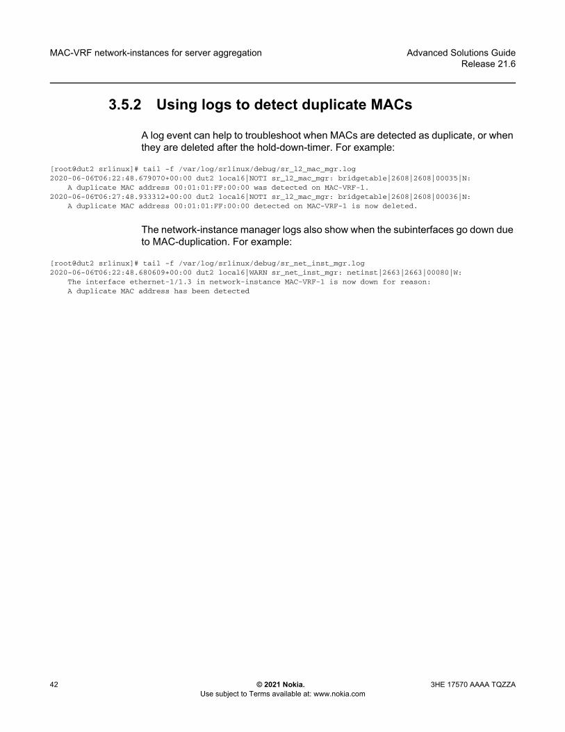
DUT2 .........................................................................................................403.5.2 Using logs to detect duplicate MACs.........................................................42

4 EVPN-VXLAN for layer-2 and multi-homing ...............................434.1 Applicability................................................................................................434.2 Overview....................................................................................................434.3 Configuring EVPN-VXLAN broadcast domains .........................................444.3.1 Configuring the underlay network..............................................................454.3.2 Configuring LEAF-3 with an EVPN-VXLAN enabled MAC-VRF................484.3.3 Checking the EVPN-VXLAN operation in MAC-VRFs...............................52

Advanced Solutions GuideRelease 21.6

4 © 2021 Nokia. Use subject to Terms available at: www.nokia.com

3HE 17570 AAAA TQZZA

4.3.4 Checking MAC mobility, MAC protection and MAC loop protection in EVPN-VXLAN BDs ................................................................................60

4.3.4.1 MAC mobility .............................................................................................614.3.4.2 MAC protection..........................................................................................634.3.4.3 MAC loop protection ..................................................................................654.4 Configuring multi-homing for EVPN broadcast domains ...........................654.4.1 All-active multi-homing configurations .......................................................674.4.1.1 Ethernet segment configuration details .....................................................674.4.2 Configuring LEAF-2 and LEAF-4 as multi-homed nodes to

server-1 .....................................................................................................694.4.2.1 Using multi-homing as all-active MLAG for non-EVPN layer-2 BDs..........734.4.3 Checking the multi-homing operation ........................................................74

5 EVPN-VXLAN for layer 3 ..............................................................815.1 Applicability................................................................................................815.2 Overview....................................................................................................815.3 Configuring EVPN-VXLAN IP-VRF domains .............................................825.3.1 Preconfiguring the underlay network .........................................................835.3.2 Configuring the LEAF-3 IP-VRF domain ...................................................835.3.3 Configuring the IP-VRF Domain on LEAF-2 and LEAF-4 .........................875.3.3.1 IRB sub-interface considerations...............................................................975.3.4 Configuring EVPN IFL interoperability to EVPN IFF unnumbered

model.........................................................................................................985.3.5 Checking the EVPN IFL model in IP-VRFs .............................................1005.3.6 Checking PE-CE routing on an IP-VRF with EVPN-IFL ..........................1075.3.6.1 Additional PE-CE considerations.............................................................1095.3.7 Checking multi-homing in an EVPN-VXLAN Layer 3 network.................1125.3.7.1 anycast-gw IPs .......................................................................................1125.3.7.2 Non-anycast-gw IP addresses.................................................................1165.3.7.3 Additional anycast gateway considerations.............................................1195.4 Testing and checking Layer 3 host mobility ............................................1205.4.1 Initial configuration - efficient host routing ..............................................1215.4.2 Mobility event - efficient host routing ......................................................1255.5 EVPN-VXLAN Layer 3 feature parity for IPv6 prefixes............................1315.5.1 Additional feature parity considerations...................................................132

6 Security hardening using CPM filters.......................................1356.1 Applicability..............................................................................................1356.2 Configuring ACL for control plane protection...........................................1356.2.1 CPM filter rules ........................................................................................1366.2.2 CPM filter configuration examples...........................................................137

Advanced Solutions GuideRelease 21.6

Getting started

3HE 17570 AAAA TQZZA © 2021 Nokia. Use subject to Terms available at: www.nokia.com

5

1 Getting startedThis chapter provides an overview of this document, includes a summary of changes from the previous release, and lists precautionary messages and command conventions.

1.1 About this document

This document describes how to configure advanced solutions for the Nokia Service Router Linux (SR Linux). Advanced solutions are defined as more complex network-level configurations where additional guidance and more detailed procedures may be required.

This document is intended for network technicians, administrators, operators, service providers, and others who need to understand how to use and configure advanced solutions.

1.2 What’s new

This following changes were made in this release.

1.3 Precautionary messages

Observe all dangers, warnings, and cautions in this document to avoid injury or equipment damage during installation and maintenance. Follow the safety procedures and guidelines when working with and near electrical equipment.

Note: This manual covers the current release and may also contain some content that will be released in later maintenance loads. Refer to the SR Linux Release Notes for information on features supported in each load.

Table 1 Change summary

Topic Location

EVPN-VXLAN L3 EVPN-VXLAN for layer 3

Getting started

6

Advanced Solutions GuideRelease 21.6

© 2021 Nokia. Use subject to Terms available at: www.nokia.com

3HE 17570 AAAA TQZZA

Table 2 describes information symbols contained in this document.

1.4 Conventions

SR Linux documentation uses the following command conventions.

• Bold type indicates a command that the user must enter.• Input and output examples are displayed in Courier text.• An open right angle bracket indicates a progression of menu choices or simple

command sequence (often selected from a user interface). Example: start > connect to

• Angle brackets (< >) indicate an item that is not used verbatim. For example, for the command show ethernet <name>, name should be replaced with the name of the interface.

• A vertical bar (|) indicates a mutually exclusive argument. • Square brackets ([ ]) indicate optional elements.• Braces ({ }) indicate a required choice. When braces are contained within square

brackets, they indicate a required choice within an optional element.• Italic type indicates a variable.

Table 2 Information symbols

Symbol Meaning Description

Danger Warns that incorrect handling and installation could result in bodily injury. An electric shock hazard could exist. Before beginning work on this equipment, be aware of hazards involving electrical circuitry, be familiar with networking environments, and implement accident prevention procedures.

Warning Warns that incorrect handling and installation could result in equipment damage or loss of data.

Caution Warns that incorrect handling may reduce component or system performance.

Note Contains suggestions or additional operational information.

Advanced Solutions GuideRelease 21.6

Getting started

3HE 17570 AAAA TQZZA © 2021 Nokia. Use subject to Terms available at: www.nokia.com

7

Generic IP addresses are used in examples. Replace these with the IP addresses used in the system.

Getting started

8

Advanced Solutions GuideRelease 21.6

© 2021 Nokia. Use subject to Terms available at: www.nokia.com

3HE 17570 AAAA TQZZA

Advanced Solutions GuideRelease 21.6

Using BGP for underlay routing

3HE 17570 AAAA TQZZA © 2021 Nokia. Use subject to Terms available at: www.nokia.com

9

2 Using BGP for underlay routingA routing protocol is needed to dynamically discover the shortest loop-free path through the underlay of a DC fabric to reach every destination IP subnet. The Border Gateway Protocol (BGP) is one of the leading technologies for this purpose due to its simplicity, scalability, and ease of multi-vendor interoperability.

BGP also provides policy mechanisms to perform hop-by-hop traffic engineering, leveraging functionality originally designed for this same purpose in the public Internet.

2.1 Applicability

The information and configuration in this chapter are based on SR Linux Release 19.11.

2.2 Overview

Figure 1 shows a 3-stage Clos fabric design using only BGP for underlay routing.

Figure 1 BGP underlay routing example

Using BGP for underlay routing

10

Advanced Solutions GuideRelease 21.6

© 2021 Nokia. Use subject to Terms available at: www.nokia.com

3HE 17570 AAAA TQZZA

The design example in Figure 1 shows the following:

• Each Top-of-Rack (TOR) switch is a BGP router assigned with its own unique Autonomous System Number (ASN).

• Each TOR switch is dual-homed to the two leaf switches in its same POD or container and adding more leaf switches later can achieve scale capacity.

• Each TOR forms one single-hop External Border Gateway Protocol (EBGP) session to each of its upstream leaf switches. From a TOR perspective, these sessions are single-hop because each leaf switch is a BGP neighbor in the same IP subnet as its interface address toward the leaf switch.

• Each leaf switch is a BGP router. All of the leaf switches in one POD or container belong to the same ASN, but this ASN is unique in the data center.

• Each leaf switch has two uplinks into the spine layer. More uplinks could be added later to achieve scale capacity. Each leaf switch forms one single-hop EBGP session with each of its upstream spine switches.

• Each spine switch is a BGP router. All of the spine switches in one data center belong to the same ASN but this ASN is unique in the network.

2.2.1 Advantages of BGP for underlay routing

Using BGP as shown in the Figure 1 example has the following advantages:

• Standard operation of the BGP best-path selection algorithm chooses the route to each destination with the AS_PATH length. This equates to the lowest hop count when each device prepends one ASN to the AS_PATH.

• Standard operation of the BGP multipath algorithm sprays traffic across all paths with the same shortest AS_PATH length.

• When a link goes down in the topology, the BGP session is taken down immediately if fast-failover is enabled. This may cause a new BGP best path to be advertised by the routers at each end of the failed session. Other routers may also advertise their own new best paths, but typically the failure does not propagate beyond routers that do not change their best path.

• Traffic can be rerouted around any node in the topology by having it prepend extra AS numbers to the AS_PATH.

• The best path or set of multipaths available to reach a destination TOR are visible in any device by looking at the AS_PATH attribute. This can be helpful with troubleshooting.

Advanced Solutions GuideRelease 21.6

Using BGP for underlay routing

3HE 17570 AAAA TQZZA © 2021 Nokia. Use subject to Terms available at: www.nokia.com

11

2.3 Configuring BGP for underlay routing

The following examples define how to bring up a static, preconfigured EBGP session between Router 3 and Router 5 (as shown in Figure 1). Use the following two examples to define the minimum configuration required for each router:

• Example: Configure Router 3 for static EBGP session• Example: Configure Router 5 for static EBGP session

2.3.1 Example: Configure Router 3 for static EBGP session

To configure Router 3:

Step 1. In candidate mode, create a network-instance that owns the IP subinterface toward Router 5.

Example:--{ candidate shared default}--[ network-instance default ]--# info detail

type defaultadmin-state enableip-load-balancing {}interface ethernet-1/1.0 {}protocols {}

Ensure the following:- The network-instance is operationally enabled.- The subinterface is operationally enabled.- The subinterface has at least one IPv4 or IPv6 address assigned.

Using BGP for underlay routing

12

Advanced Solutions GuideRelease 21.6

© 2021 Nokia. Use subject to Terms available at: www.nokia.com

3HE 17570 AAAA TQZZA

Step 2. Add the BGP protocol to the network-instance. By default, it is administratively enabled when the configuration is committed.

Example:--{ candidate shared default}--[ network-instance default ]--# protocols bgp

Step 3. Assign a global ASN to the BGP instance. This is the ASN reported to peers when this network-instance opens a BGP session toward another router (unless it is overridden by a local-as configuration). Router 3 has a global ASN of 65201.

Example:--{ candidate shared default}--[ network-instance default protocols bgp ]--# autonomous-system 65201

Step 4. Assign a router-ID to the BGP instance. This is the BGP identifier reported to peers when this network-instance opens a BGP session toward another router. This overrides the router-id configuration at the network-instance level. Router 3 has a router-id of 192.0.3.1.

Example:--{ candidate shared default}--[ network-instance default protocols bgp ]--# router-id 192.0.3.1

Step 5. Enable all address families that should be enabled globally as a default for all peers of the BGP instance. When you later configure individual neighbors or groups, you can override the enabled families at those levels.

Example:--{ candidate shared default}--[ network-instance default protocols bgp ]--# ipv4-unicast admin-state enable--{ candidate shared default}--[ network-instance default protocols bgp ]--# ipv6-unicast admin-state enable

Step 6. Create a peer group to contain the neighbor session with Router 5. A peer-group should include sessions that have a similar or almost identical configuration.

Advanced Solutions GuideRelease 21.6

Using BGP for underlay routing

3HE 17570 AAAA TQZZA © 2021 Nokia. Use subject to Terms available at: www.nokia.com

13

In this example, the peer group is named "spine" since it will be used to contain all spine layer peers. New groups are administratively enabled by default.

Example:--{ candidate shared default}--[ network-instance default protocols bgp ]--# group spine

Step 7. All of the configuration that is common to all peers in the group must be configured at the group level. In this example, this includes:- peer-as (of the spine peers)- export-policy

The export policy (named “pass-all” in the example) in the configuration output below was previously created in this work flow (if it does not exist, the commit fails). The export policy is required to advertise any routes to R5. This is because R5 is an EBGP peer, and by default, no routes are advertised to EBGP peers without an export policy. Note: this can be controlled by a setting in the network-instance protocols “bgp ebgp-default-policy” container.The "pass-all" export policy matches and accepts all BGP routes, while rejecting all non-BGP routes.

Example:--{ candidate shared default}--[ network-instance default protocols bgp group spine ]--# info

peer-as 65301export-policy pass-all

--{ candidate shared }--[ ]# info from running routing-policy

routing-policy {policy pass-all {

default-action {reject {}

}statement 10 {

match {protocol bgp

}action {

accept}

}}

}

Using BGP for underlay routing

14

Advanced Solutions GuideRelease 21.6

© 2021 Nokia. Use subject to Terms available at: www.nokia.com

3HE 17570 AAAA TQZZA

Step 8. Configure the BGP session with router R5. In this example, router R5 is reachable to R3 through the ethernet-1/1.0 subinterface. On this subnet, router R5 has the global-unicast IPv6 address 2001:db8::c11. In this minimal configuration example, the only required configuration for the neighbor is its association with the group "spine" that was previously created. New neighbors are administratively enabled by default.

Example:--{ candidate shared default}--[ network-instance default protocols bgp ]--# neighbor 2001:db8::c11 peer-group spine

Step 9. Review all changes and, if everything appears correct, commit the changes:

# commit stay

Advanced Solutions GuideRelease 21.6

Using BGP for underlay routing

3HE 17570 AAAA TQZZA © 2021 Nokia. Use subject to Terms available at: www.nokia.com

15

2.3.2 Example: Configure Router 5 for static EBGP session

To configure Router 5:

Step 1. In candidate mode, create a network-instance that owns the IP subinterface toward Router 3. Ensure that:- The network-instance is operationally enabled.- The subinterface is operationally enabled.- The subinterface has at least one IPv4 or IPv6 address assigned.

Example:--{ candidate shared default}--[ network-instance default ]--# info detail

type defaultadmin-state enableip-forwarding {

receive-ipv4-check truereceive-ipv6-check true

}ip-load-balancing {}interface ethernet-3/1.1 {}protocols {}mtu {

path-mtu-discovery truemin-path-mtu 552

}

Step 2. Add the BGP protocol to the network-instance. By default, it is administratively enabled when the configuration is committed.

Example:--{ candidate shared default}--[ network-instance default ]--# protocols bgp

Using BGP for underlay routing

16

Advanced Solutions GuideRelease 21.6

© 2021 Nokia. Use subject to Terms available at: www.nokia.com

3HE 17570 AAAA TQZZA

Step 3. Assign a global autonomous system number to the BGP instance. Router 5 has a global autonomous system number of 65301.

Example:--{ candidate shared default}--[ network-instance default protocols bgp ]--# autonomous-system 65301

Step 4. Assign a router-ID to the BGP instance. This is the BGP identifier reported to peers when this network-instance opens a BGP session toward another router. This overrides the router-ID configuration at the network-instance level. Router 5 has a router-ID of 192.0.5.1.

Example:--{ candidate shared default}--[ network-instance default protocols bgp ]--# router-id 192.0.5.1

Step 5. Enable all address families that should be enabled globally as a default for all peers of the BGP instance. When you later configure individual neighbors or groups, you can override the enabled families at those levels.

Example:--{ candidate shared default}--[ network-instance default protocols bgp ]--# ipv4-unicast admin-state enable--{ candidate shared default}--[ network-instance default protocols bgp ]--# ipv6-unicast admin-state enable

Step 6. Create a peer-group to contain the neighbor session with Router 3. A peer-group should include sessions that have a similar or almost identical configuration. In this example, the peer-group is named "leaf-pod1" since it is used to contain all leaf peers in POD1. New groups are administratively enabled by default.

Example:--{ candidate shared default}--[ network-instance default protocols bgp ]--# group leaf-pod1

Advanced Solutions GuideRelease 21.6

Using BGP for underlay routing

3HE 17570 AAAA TQZZA © 2021 Nokia. Use subject to Terms available at: www.nokia.com

17

Step 7. All of the configuration that is common to all peers in the group must be configured at the group level. In this example, this includes:- peer-as (of the leaf peers in POD1)- export-policy

The export policy (named “pass-all” in the example) is shown in the following running configuration output, and is required to advertise any routes to R3. This is because R3 is an EBGP peer and, by default, no routes are advertised to EBGP peers without an export policy. Note: This can be controlled by a setting in the network-instance protocols “bgp ebgp-default-policy” container.The "pass-all" export policy is a simple policy that matches all BGP routes and accepts them, while rejecting all non-BGP routes.

Example:--{ candidate Shared default}--[ network-instance default protocols bgp group leaf-pod1 ]--# info

peer-as 65201export-policy pass-all

--{ candidate }--[ network-instance default protocols bgp group leaf-pod1 ]--# exit all--{ candidate shared default}--[ ]# info from running routing-policy

routing-policy {policy pass-all {

default-action {reject {}

}statement 10 {

match {protocol bgp

}action {

accept}

}

Step 8. Configure the BGP session with router R3. In this example, router R3 is reachable to R5 through the ethernet-3/1.1 subinterface. On this subnet, router R5 has the global-unicast IPv6 address 2001:db8::c12. In this minimal configuration example, the only required configuration for the neighbor is its association with the group “leaf-pod1” that was previously created. New neighbors are administratively enabled by default.

Example:--{ candidate shared default}--[ network-instance default protocols bgp ]--# neighbor 2001:db8::c12 peer-group leaf-pod1

Using BGP for underlay routing

18

Advanced Solutions GuideRelease 21.6

© 2021 Nokia. Use subject to Terms available at: www.nokia.com

3HE 17570 AAAA TQZZA

Step 9. Review all changes and if everything looks correct, commit the changes.Step 10. From Router 3, verify that the session is up (State is established) using the

show neighbor command under the network-instance protocols BGP hierarchy.

Example:--{running}--{ network-instance default protocols bgp }--srlinux# show neighbor------------------------------------------------------------------------------------------------BGP neighbor summary for network-instance "default"Flags: S static, D dynamic, L discovered by LLDP, B BFD enabled, - disabled, * slow------------------------------------------------------------------------------------------------+----------+---------------+-------+-------+-------+-------------+----------+--------------+---------+| Net-Inst | Peer | Group | Flags | Peer- | State | Uptime | AFI/SAFI | RX/ || | | | | AS | | | | Active || | | | | | | | | /TX |+==========+===============+=======+=======+=======+=============+==========+==============+=========+| default | 2001:db8::cli | spine | S | 65301 | established | 0d:0h: | ipv4-unicast | [4/3/1] || | | | | | | 34min 7s | ipv6-unicast | [1/1/1] |+----------+---------------+-------+-------+-------+-------------+----------+--------------+---------+------------------------------------------------------------------------------------------------Summary:1 configured neighbors, 1 configured sessions are established, 0 disabled peersNone dynamic sessions are established

Advanced Solutions GuideRelease 21.6

Using BGP for underlay routing

3HE 17570 AAAA TQZZA © 2021 Nokia. Use subject to Terms available at: www.nokia.com

19

2.4 Advanced configuration: BGP timers

When two BGP routers form a session, they each propose a value for the session hold-time in their OPEN messages. The lowest of the two proposed values becomes the operational hold-time for the lifetime of the session. If the operational hold-time is greater than zero, both routers are agreeing to send keepalive messages to each other. This ensures that any loss of connectivity between them can be detected.

Each router restarts its hold-timer every time it receives a message from the other peer. If the operational hold-timer reaches zero without receiving any keepalive or related message from the peer, the session is torn down (returned to the Idle state). Each router sends a keepalive message to its peer no more than one message every keepalive interval. The default value for the keepalive interval is one third of the operational hold-time, but it possible to configure a different interval.

In a data center environment, an EBGP session failure is usually caused by an interface going down. Interface events are propagated to BGP if fast-failover is enabled. The hold-timer expiry is not the usual mechanism for detecting connectivity problems. However, there may be some circumstances where some adjustment of the hold-time and/or the keepalive interval can be used.

2.4.1 Timer-related defaults and how to modify

With the SR Linux, the default hold-time is 90 seconds and the default keepalive interval is 30 seconds. To change the hold-time on a session to 24 seconds with a keepalive interval of 8 seconds (1/3 of 24), you only need to change the hold-time value to 24, as shown in the following example:

--{ candidate shared default}--[ network-instance default protocols bgp neighbor2001:db8::c11 ]--

# timers hold-time 24

After this change is committed, the affected session flaps and the new operational timer values are shown in the output of the show network-instance protocols bgp neighbor detail command. For example:

srlinux# show network-instance default protocols bgp neighbor 2001:db8::c11 detail----------------------------------------------------------------------------------Peer : 2001:db8::c11, remote AS: 65301, local AS: 65201Type : staticDescription : NoneGroup : spineExport policies : pass-allImport policies: pass-all---------------------------------------------------------------------------------

Using BGP for underlay routing

20

Advanced Solutions GuideRelease 21.6

© 2021 Nokia. Use subject to Terms available at: www.nokia.com

3HE 17570 AAAA TQZZA

Admin-state is enable, session-state is established, up for 0d:0h:6m:37sTCP connection is 2001:db8::c12 [45492] -> 2001:db8::c11 [179]0 messages in input queue, 0 messages in output queue--------------------------------------------------------------------------------Last-state was active, last-event was recvOpen, 24 peer-flapsLast received Notification was Error:Message Header Error SubError: Bad Message TypeFailure detection: BFD is False, fast-failover is False------------------------------------------------------------------------------------Graceful Restart

Restarts by the peer : 0Last restart : N/APeer requested restart-time : 300Stale routes time : 360

+-----------------------------------+---------------------------------+------------+| Timer | Configured/Operational | Next |+===================================+=================================+============+| connect-retry | 120 | - || keepalive-interval | 30/8 | - || hold-time | 24/24 | - || minimum-advertisement-interval | 5 | - |+-----------------------------------+---------------------------------+------------+------------------------------------------------------------------------------------Cap Sent: MP_BGP ROUTE_REFRESH EXT_NH_ENCODING 4-OCTET_ASNCap Recv: MP_BGP ROUTE_REFRESH EXT_NH_ENCODING 4-OCTET_ASN------------------------------------------------------------------------------------+----------------------------------+--------------------------------+--------------+| Messages | Sent | Received |+==================================+================================+==============+| Non Updates | 55 | 52 || Updates | 424 | 2 || Malformed updates | 0 | 0 |+----------------------------------+--------------------------------+--------------+------------------------------------------------------------------------------------Ipv4-unicast AFI/SAFI

End of RIB : sent, not receivedReceived routes : 4Rejected routes : NoneActive routes : 3Advertised routes : 1Prefix-Limit : NoneDefault originate : disabledAdvertise with IPv6 next-hops : FalsePeer requested GR helper : NonePeer preserved forwarding state: None

-----------------------------------------------------------------------------------Ipv6-unicast AFI/SAFI

End of RIB : sent, not receivedReceived routes : 1Rejected routes : NoneActive routes : 1Advertised routes : 1Prefix-Limit : NoneDefault originate : disabledAdvertise with IPv6 next-hops : N/APeer requested GR helper : NonePeer preserved forwarding state: None

-------------------------------------------------------------------------------------{ candidate shared }--[ ]--

Advanced Solutions GuideRelease 21.6

Using BGP for underlay routing

3HE 17570 AAAA TQZZA © 2021 Nokia. Use subject to Terms available at: www.nokia.com

21

2.5 Advanced configuration: BGP convergence optimization

By default, the SR Linux BGP process (running the BGP control plane) does not advertise a route for an IPv4 or IPv6 prefix until it has positive confirmation from the FIB manager process that the route is in the FIB of all installed line cards. This ensures that the router does not attract traffic destined for an IP prefix until all line cards have the ability to forward the traffic. Note: The BGP process does not delay route withdrawals until it knows that all line cards have removed the FIB state as this is not needed.

Nokia recommends that the wait-for-fib-install functionality remain enabled on routers that are in the datapath (that is, routers that set BGP next-hop-self). However, this does cause the rate of RIB-OUT route advertisements to slow to the rate of FIB programming. If the objective of a BGP performance test is to reach the highest possible route advertisement rate, set the wait-for-fib-install configuration leaf to false. For example:

--{ candidate shared default}--[network-instance default protocols bgp route-advertisement]--# wait-for-fib-install false

2.5.1 Optimizing the convergence process after restarts

The BGP protocol and its state machine must attempt to reconverge whenever the following occurs:

• the router starts up• the BGP manager (control plane) application restarts• all peers of a network-instance are hard-reset by a tools reset-peer command

When any of these conditions are met, the router resynchronizes its BGP RIB with the BGP RIB of other routers in the network. When resynchronization completes, BGP has "converged". During convergence, the following occurs to the restarting router:

• It must reestablish its sessions with configured (and discovered) BGP neighbors.

• It must relearn all BGP routes advertised by its direct BGP neighbors (their best paths, plus potentially some additional paths).

• It must advertise to its direct neighbors, its own locally originated BGP routes plus the received routes that it considers its own set of best paths.

Using BGP for underlay routing

22

Advanced Solutions GuideRelease 21.6

© 2021 Nokia. Use subject to Terms available at: www.nokia.com

3HE 17570 AAAA TQZZA

The default behavior of SR Linux BGP is to execute all of the preceding steps in parallel. As soon as the first BGP session has reestablished, the restarting router begins to advertise its own best paths to that BGP neighbor (even though it is still in the early stages of rebuilding its RIB-IN database).

As more sessions come up and more routes are learned, it is likely that routes previously considered best are no longer best, leading to multiple route advertisements for the same prefix with each incrementally better than the previous one. The best route is not determined until the last advertisement. The intermediate route advertisements can substantially increase the processing workload on the restarting router as well as its BGP neighbors. This can lengthen the overall convergence time and cause short term inefficiencies in traffic forwarding.

Instead of reconverging as previously described, SR Linux BGP can also be configured to delay the advertisement of BGP routes in a particular address family until convergence has occurred for that address family or until a configured time limit has expired. This behavior is activated by configuring a non-zero value for the min-wait-to-advertise configuration leaf. For example:

--{ candidate shared default}--[ network-instance default protocols bgp convergence ]--# min-wait-to-advertise 600

The max-wait-to-advertise leaf value for the IPv4-unicast and IPv6-unicast address families can be configured, or you can accept their default values (3x the min-wait-to-advertise value). If configuring a max-wait-to-advertise leaf with a non-default value, the value must be greater than the configured min-wait-to-advertise timer. In the following example, the max-wait-to-advertise timer is set to 900 seconds for IPv4-unicast and set to 800 seconds for IPv6-unicast.

--{ candidate shared default}--[ network-instance default protocols bgp ]--# ipv4-unicast convergence max-wait-to-advertise 900# ipv6-unicast convergence max-wait-to-advertise 800

The min-wait-to-advertise timer begins after one of the following triggers occurs and the first BGP session becomes established.

• BGP instance admin state set to enable or disable• Running tools clear network-instance protocols bgp reset-peer • BGP application restart• Node reboot

When the first session that supports the exchange of IPv4-unicast routes is established, the max-wait-to-advertise timer of the IPv4 address family starts. Likewise, when the first session that supports the exchange of IPv6-unicast routes is established, the max-wait-to-advertise timer of the IPv6 address family starts.

Advanced Solutions GuideRelease 21.6

Using BGP for underlay routing

3HE 17570 AAAA TQZZA © 2021 Nokia. Use subject to Terms available at: www.nokia.com

23

While the min-wait-to-advertise timer is running, BGP sessions come up, and routes are learned and sorted according to preference by the BGP decision process. However, no routes are advertised to any of the peers.

When the min-wait-to-advertise expires, BGP makes a list of IPv4 and IPv6 peers (that is, peers that support the exchange of IPv4-unicast routes and IPv6-unicast routes). It expects to receive the IPv4-unicast End of RIB (EOR) marker from each neighbor in the list of IPv4 peers, and it expects to receive the IPv6-unicast EOR from each neighbor in the list of IPv6 peers.

When BGP in the restarting router receives the last expected IPv4-unicast EOR, it declares that address family as converged and starts to advertise its best IPv4-unicast routes. Likewise, when BGP receives the last expected IPv6-unicast EOR, it declares that address family as converged and starts to advertise its best IPv6-unicast routes.

If the max-wait-to-advertise timer expires before the last expected EOR, is received for an address family, the convergence state for the address family moves to “timeout” and a RIB-OUT advertisement is triggered. This occurs even though convergence is not complete. The max-wait-to-advertise timers are fail-safe. They handle the scenario when one or more peers come up within the min-wait-to-advertise window, but their EORs are not sent.

In the example that follows, the BGP convergence process is triggered by a hard reset of all peers of the BGP instance:

--{ * candidate shared default}--[ ]--dut1# tools network-instance default protocols bgp reset-peer/network-instance[name=default]/protocols/bgp:

Successfully executed the tools clear command.--{ candidate shared }--[ ]--

If the show network-instance protocols bgp summary command is issued a few minutes after the session restarts, a snapshot of the convergence process can be viewed. For example, in the following sample output, ten IPv4-unicast sessions are established when the min-wait-to-advertise timer expires and IPv4-unicast convergence takes 517 seconds.

dut1# show network-instance default protocols bgp summary-----------------------------------------------------------------------------BGP is enabled and up in network-instance "default"Global AS number : 65201BGP identifier : 192.0.3.1-----------------------------------------------------------------------------

Total paths : 27Received routes : 200000Received and active routes: 200000Total UP peers : 20Configured peers : 20, 0 are disabledDynamic peers : None

Using BGP for underlay routing

24

Advanced Solutions GuideRelease 21.6

© 2021 Nokia. Use subject to Terms available at: www.nokia.com

3HE 17570 AAAA TQZZA

-----------------------------------------------------------------------------Default preferences

BGP Local Preference attribute: 100EBGP route-table preference : 170IBGP route-table preference : 170

-----------------------------------------------------------------------------Wait for FIB install to advertise: TrueSend rapid withdrawals : False-----------------------------------------------------------------------------Ipv4-unicast AFI/SAFI

Received routes : 100000Received and active routes : 100000Max number of multipaths : 8, 1Multipath can transit multi AS: True

-----------------------------------------------------------------------------Min adv delay after restart(slow peer thresh): 600sCurrently established sessions : 10Sessions established at slow peer thresh : 10First session establishment after restart : 5sLast session established after restart : 252s

-----------------------------------------------------------------------------Max advertisement delay after first peer UP: 900sMax adv delay exceeded after last restart : NoneCurrent convergence state : convergedConverged peers : 10Convergence time after last restart : 517s

-----------------------------------------------------------------------------Ipv6-unicast AFI/SAFI

Received routes : 100000Received and active routes : 100000Max number of multipaths : 1,1Multipath can transit multi AS: True

-----------------------------------------------------------------------------Min adv delay after restart(slow peer thresh): 600sCurrently established sessions : 10Sessions established at slow peer thresh : 10First session establishment after restart : 8sLast session established after restart : 312s

-----------------------------------------------------------------------------Max advertisement delay after first peer UP: 800sMax adv delay exceeded after last restart : NoneCurrent convergence state : convergedConverged peers : 10Convergence time after last restart : 705s

-------------------------------------------------------------------------------{ candidate shared }--[ ]--

Advanced Solutions GuideRelease 21.6

Using BGP for underlay routing

3HE 17570 AAAA TQZZA © 2021 Nokia. Use subject to Terms available at: www.nokia.com

25

2.6 Advanced configuration: Advertising IPv4 routes with IPv6 next-hops

Some data centers are migrating away from an IPv4/IPv6 dual-stack infrastructure and moving toward an IPv6-only infrastructure. In an IPv6-only design, each interface in the fabric (such as the leaf-spine, leaf-TOR) is assigned one or more IPv6 addresses, but no IPv4 addresses.

To route and forward IPv4 packets over an IPv6-only fabric, the leaf and spine switches must support the following:

• The ability to advertise a BGP route for IPv4 Network Level Reachability Information (NLRI) with an IPv6 BGP next-hop address.

• The ability to receive a BGP route for IPv4 NLRI with an IPv6 BGP next-hop address.

• The ability to accept IPv4 packets on an IPv6-only interface.

2.6.1 Advertising a BGP route for IPv4 NLRI with an IPv6 BGP next-hop address

On the SR Linux, the ability to advertise a BGP route for IPv4 NLRI with an IPv6 BGP next-hop address is not enabled by default. To enable, use the advertise-ipv6-next-hops command, which is available on a per-session basis. The following is a sample configuration:

--{ candidate shared default}--[ network-instance default protocols bgp ]--# ipv4-unicast advertise-ipv6-next-hops true

2.6.2 Receiving a BGP route for IPv4 NLRI with an IPv6 BGP next-hop address

On the SR Linux, the ability to receive a BGP route for IPv4 NLRI with an IPv6 BGP next-hop address is not enabled by default. To enable, use the receive-ipv6-next-hops command, which is available on a per-session basis.

Using BGP for underlay routing

26

Advanced Solutions GuideRelease 21.6

© 2021 Nokia. Use subject to Terms available at: www.nokia.com

3HE 17570 AAAA TQZZA

This command allows SR Linux to advertise the extended-next-hop-encoding BGP capability, defined in RFC 5549, to the peers included in the scope of the command. This BGP capability encodes NLRI AFI 1, NLRI SAFI 1, and next-hop AFI 2. It informs peers that they can advertise MP-BGP encoded IPv4 routes with IPv6 next-hops. When the routes are received, the router will then attempt to resolve them using IPv6 routes.

If the router receives an IPv4 route with an IPv6 next-hop that is resolved by a static or direct IPv6 route (and an IPv6 neighbor entry for the next-hop host address), the IPv4 route is programmed in the FIB so that matching IPv4 packets are sent without additional encapsulation. Packets are sent through the indicated interface with a MAC destination address provided by the IPv6 neighbor entry.

The following is a sample configuration:

--{ candidate shared }--[ network-instance default protocols bgp ]--# ipv4-unicast receive-ipv6-next-hops true

2.6.3 Accepting IPv4 packets on an IPv6-only interface

The datapath of the SR Linux checks for and discards all IPv4 packets that are received on an IPv6-only subinterface (that is, a subinterface with no configured IPv4 addresses). This is done for security reasons. However, if the router has advertised IPv4 routes with IPv6 next-hops to a peer, the check should be disabled on all subinterfaces that could be used by the peer when it installs the IPv4 route.

To disable this check on all subinterfaces bound to a specific network-instance, set the ipv4-receive-check leaf to false.

The following is a sample configuration:

--{ candidate shared default}--[ network-instance default ]--# ip-forwarding receive-ipv4-check false

Advanced Solutions GuideRelease 21.6

MAC-VRF network-instances for server aggregation

3HE 17570 AAAA TQZZA © 2021 Nokia. Use subject to Terms available at: www.nokia.com

27

3 MAC-VRF network-instances for server aggregation

MAC-VRF network-instances can provide aggregation for a group of servers into the same subnet. This chapter defines concepts and procedures for configuring MAC-VRF network-instances and Integrated Routing and Bridging (IRB) subinterfaces.

3.1 Applicability

The information and configuration in this chapter are based on SR Linux Release 20.6.

3.2 Overview

Data Center (DC) servers or hosts are connected to TOR routers so that they can be reached from other TOR routers in the same IP fabric. The TOR nodes use BGP to learn and propagate subnet reachability in the underlaying routing infrastructure. The servers or hosts connected to these TOR BGP routers use routed subinterfaces on the TOR, and static routes or a PE-CE BGP session, to learn or advertise reachability to the rest of the DC.

Each server requires a separate routed subinterface and subnet on the TOR, and the number of subinterfaces and local routes in the route-table grows linearly as the number of servers increases. The use of a MAC-VRF network-instance provides aggregation for a group of servers into the same subnet. This saves routes and subinterfaces in the TOR. A MAC-VRF is attached to the default network-instance by a single IRB interface and subnet, instead of a separate subinterface and route per server. Figure 2 shows an example of MAC-VRF network-instances for server aggregation.

MAC-VRF network-instances for server aggregation

28

Advanced Solutions GuideRelease 21.6

© 2021 Nokia. Use subject to Terms available at: www.nokia.com

3HE 17570 AAAA TQZZA

Figure 2 MAC-VRF network-instances for server aggregation

Figure 2 shows Leaf-1 and Leaf-2 configured with MAC-VRF instances that aggregate a group of servers. These servers are assigned IP addresses on the same subnet and are connected to the leaf default network-instance by a single IRB subinterface. The servers use a PE-CE BGP session with the IRB IP address to exchange reachability. The use of the MAC-VRF with an IRB subinterface saves routed subinterfaces on the default network-instance; only one routed subinterface is needed instead of one per server.

sw2010

Spine

NET-INSTDefault

NET-INSTDefault

MAC-VRF 120.0/26

MAC-VRF 110.0/26

IRB1.120.1

IRB1.110.1

BGP

Peer

BGP

Peer

If110.2

If110.3

If110.4

If120.2

If120.3

If120.4

Spine

ServersServers

Leaf-1 Leaf-2

Advanced Solutions GuideRelease 21.6

MAC-VRF network-instances for server aggregation

3HE 17570 AAAA TQZZA © 2021 Nokia. Use subject to Terms available at: www.nokia.com

29

3.3 Configuring MAC-VRF network-instances and IRB subinterfaces

Figure 3 shows an example of how to configure MAC-VRF network-instances and their IRB subinterfaces to the default network-instance, and how EBGP sessions are configured with the servers. In this example, DUT2 is the TOR being configured. DUT1 and DUT3 are servers that are running BGP against the DUT2 IRB subinterface.

Figure 3 MAC-VRF and IRB example in DUT2

3.3.1 Example: Configure DUT2 with MAC-VRF, IRB, and static BGP on IRB

This example shows how to configure the DUT2 with a MAC-VRF, bridged subinterfaces to DUT1 and DUT3, and an IRB subinterface (see Figure 3).

sw2011

Spine

NET-INSTDefault

NET-INSTDefault

MAC-VRF 1MAC-VRF 110.0.0.0/24

2001:db8::/64

IRB1.1IRB1.110.0.0.22001:db8::2/64

VLAN100 VLAN100

BGP

Peer BG

P Pe

er

ethernet-1/1.110.0.0.1/24

2001:db8::1/64

ethernet-1/1.110.0.0.3/24

2001:db8::3/64

If1 If1 If1

Spine

Servers

DUT1 DUT3

DUT2 TOR

MAC-VRF network-instances for server aggregation

30

Advanced Solutions GuideRelease 21.6

© 2021 Nokia. Use subject to Terms available at: www.nokia.com

3HE 17570 AAAA TQZZA

Step 1. In candidate mode, create the interfaces and bridged subinterfaces to connect to DUT1 and DUT3. In this example:- Connect ethernet-1/1 and ethernet-1/2 to DUT1 and DUT3,

respectively. Although these interfaces could be defined untagged, this example configures them as tagged (vlan-tagging true).

- Create a subinterface with index 1 under each interface. The subinterface must be configured as type bridged. Bridged subinterfaces can be associated with MAC-VRF instances so that MAC learning and layer-2 forwarding can be enabled on them.

- The subinterfaces use vlan-id 100 since this is the VLAN ID used by the servers (DUT1 and DUT2) to send and receive frames.

Example:--{ candidate shared default }--[ interface * ]--A:dut2# info

interface ethernet-1/1 {description dut2-dut1vlan-tagging truesubinterface 1 {

type bridgedvlan {

encap {single-tagged {

vlan-id 100}

}}

}}interface ethernet-1/2 {

description dut2-dut3vlan-tagging truesubinterface 1 {

type bridgedvlan {

encap {single-tagged {

vlan-id 100}

}}

}}

Note: This example assumes DUT2 is pre-configured with a default network-instance that runs BGP sessions to the spine routers, as defined in the section: Using BGP for underlay routing.

Advanced Solutions GuideRelease 21.6

MAC-VRF network-instances for server aggregation

3HE 17570 AAAA TQZZA © 2021 Nokia. Use subject to Terms available at: www.nokia.com

31

Step 2. Configure an IRB interface and subinterface to connect the MAC-VRF to the existing default network-instance. The IRB is configured in a similar way to a loopback interface and subinterfaces. The IRB subinterface must be type routed, but does not need to be explicitly configured as routed.

Example:--{ candidate shared default }--[ interface irb* ]--A:dut2# info

interface irb1 {subinterface 1 {

ipv4 {address 10.0.0.2/24 {}

}ipv6 {

address 2001:db8::2/64 {}

}}

}

Step 3. Configure the network-instance type mac-vrf and associate it with the bridged and IRB interfaces.

Example:--{ candidate shared default }--[ network-instance MAC-VRF-1 ]--A:dut2# info

type mac-vrfadmin-state enableinterface ethernet-1/1.1 {}interface ethernet-1/2.1 {}interface irb1.1 {}

Step 4. Associate the same IRB interface with the network-instance default and configure the BGP IPv4 and IPv6 neighbors to DUT1 and DUT3. See Using BGP for underlay routing for more information about configuring BGP sessions.

Example:--{ candidate shared default }--[ network-instance default ]--A:dut2# info

type defaultadmin-state enablerouter-id 2.2.2.2interface irb1.1 {}interface lo0.1 {

MAC-VRF network-instances for server aggregation

32

Advanced Solutions GuideRelease 21.6

© 2021 Nokia. Use subject to Terms available at: www.nokia.com

3HE 17570 AAAA TQZZA

}protocols {

bgp {admin-state enableautonomous-system 64502router-id 10.0.0.2ebgp-default-policy {

import-reject-all false}failure-detection {

enable-bfd truefast-failover true

}group tor {

admin-state enableexport-policy pass-allipv4-unicast {

admin-state enable}ipv6-unicast {

admin-state enable}local-as 64502 {}timers {

minimum-advertisement-interval 1}trace-options {

flag update {}flag graceful-restart {}flag events {}flag keepalive {}flag notification {}flag open {}flag packets {}flag route {}flag socket {}flag timers {}

}}ipv4-unicast {

admin-state enable}ipv6-unicast {

admin-state enable}neighbor 10.0.0.1 {

peer-as 64501peer-group tor

Advanced Solutions GuideRelease 21.6

MAC-VRF network-instances for server aggregation

3HE 17570 AAAA TQZZA © 2021 Nokia. Use subject to Terms available at: www.nokia.com

33

transport {local-address 10.0.0.2

}}neighbor 10.0.0.3 {

peer-as 64503peer-group tortransport {

local-address 10.0.0.2}

}neighbor 2001:db8::1 {

peer-as 64501peer-group tortransport {

local-address 2001:db8::2}

}neighbor 2001:db8::3 {

peer-as 64503peer-group tortransport {

local-address 2001:db8::2}

}}

}

Step 5. Review all the changes and commit if correct.

Example:--{ candidate shared default }--[ ]--A:dut2# commit stay

Step 6. Check the state of the MAC-VRF and the connectivity to DUT1 and DUT3 using the following commands: - show network-instance MAC-VRF-1 interfaces- show network-instance default interfaces- show network-instance MAC-VRF-1 bridge-table mac-table all- show arpnd arp-entries interface irb1 - show arpnd neighbors interface irb1 - show network-instance default protocols bgp neighbor

Example:A:dut2# show network-instance MAC-VRF-1 interfaces====================================================================Net instance : MAC-VRF-1Interface : ethernet-1/1.1Type : bridged

MAC-VRF network-instances for server aggregation

34

Advanced Solutions GuideRelease 21.6

© 2021 Nokia. Use subject to Terms available at: www.nokia.com

3HE 17570 AAAA TQZZA

Oper state : up====================================================================Net instance : MAC-VRF-1Interface : ethernet-1/2.1Type : bridgedOper state : up====================================================================Net instance : MAC-VRF-1Interface : irb1.1Oper state : upIp mtu : 1500

Prefix Origin Status==================================================================10.0.0.2/24 static2001:db8::2/64 static preferredfe80::201:2ff:feff:41/64 link-layer preferred

====================================================================

A:dut2# show network-instance default interfaces====================================================================Net instance : defaultInterface : irb1.1Oper state : upIp mtu : 1500

Prefix Origin Status====================================================================10.0.0.2/24 static2001:db8::2/64 static preferredfe80::201:2ff:feff:41/64 link-layer preferred

=====================================================================Net instance : defaultInterface : lo0.1Oper state : up

Prefix Origin Status====================================================================2.2.2.2/32 static2001:db8:1::2/128 static preferred

=====================================================================

A:dut2# show network-instance MAC-VRF-1 bridge-table mac-table all------------------------------------------------------------------------------------------------------Mac-table of network instance MAC-VRF-1------------------------------------------------------------------------------------------------------+-------------------+----------------+-------+-----------+--------+-------+--------------------------+| address | Destination | Dest | Type | Active | Aging | Last Update || | | Index | | | | |+===================+================+=======+===========+========+=======+==========================+| 00:01:01:FF:00:00 | ethernet-1/1.1 | 16 | learnt | true | 287 | 2020-06-03T13:40:25.000Z || 00:01:02:FF:00:41 | irb-interface | 0 | irb- | true | N/A | 2020-06-02T13:53:50.000Z || | | | interface | | | || 00:01:03:FF:00:00 | ethernet-1/2.1 | 17 | learnt | true | 287 | 2020-06-03T13:40:25.000Z |

Advanced Solutions GuideRelease 21.6

MAC-VRF network-instances for server aggregation

3HE 17570 AAAA TQZZA © 2021 Nokia. Use subject to Terms available at: www.nokia.com

35

+-------------------+----------------+-------+-----------+--------+-------+--------------------------+Total Irb Macs : 1 Total 1 ActiveTotal Static Macs : 0 Total 0 ActiveTotal Duplicate Macs : 0 Total 0 ActiveTotal Learnt Macs : 2 Total 2 ActiveTotal Macs : 3 Total 3 Active---------------------------------------------------------------------------------------------------

A:dut2# show arpnd arp-entries interface irb1+-----------+--------------+----------+---------+----------------------+-------------------+| Interface | Subinterface | Neighbor | Origin | Link layer address | Expiry |+===========+==============+=================+=========+===============+===================+| irb1 | 1 | 10.0.0.1 | dynamic | 00:01:01:FF:00:00 | 3 hours from now || irb1 | 1 | 10.0.0.3 | dynamic | 00:01:03:FF:00:00 | 3 hours from now |+-----------+--------------+----------+---------+----------------------+-------------------+--------------------------------------------------------------------------------------------

Total entries : 2 (0 static, 2 dynamic)--------------------------------------------------------------------------------------------

A:dut2# show arpnd neighbors interface irb1+-----------+-----------+----------------+---------+--------------------+---------+------------+--------+| Interface | Sub | Neighbor | Origin | Link layer address | Current | Next state | Is || | interface | | | | state | change | Router |+===========+===========+================+=========+====================+=========+============+========+| irb1 | 1 | 2001:db8::1 | dynamic | 00:01:01:FF:00:00 | stale | 2 hours | true || | | | | | | from now | || irb1 | 1 | 2001:db8::3 | dynamic | 00:01:03:FF:00:00 | stale | 2 hours | true || | | | | | | from now | || irb1 | 1 | fe80::201:1ff: | dynamic | 00:01:01:FF:00:00 | stale | 2 hours | true || | | feff:0 | | | | from now | || irb1 | 1 | fe80::201:3ff: | dynamic | 00:01:03:FF:00:00 | stale | 2 hours | true || | | feff:0 | | | | from now | |+-----------+-----------+----------------+---------+--------------------+---------+------------+--------+---------------------------------------------------------------------------------------------------------

Total entries : 4 (0 static, 4 dynamic)---------------------------------------------------------------------------------------------------------

A:dut2# show network-instance default protocols bgp neighbor--------------------------------------------------------------------------------------------------------BGP neighbor summary for network-instance "default"Flags: S static, D dynamic, L discovered by LLDP, B BFD enabled, - disabled, * slow---------------------------------------------------------------------------------------------------------+----------+-------------+-------+------+-------+-------------+---------------+------------+------------+| Net-Inst | Peer | Group | Flag | Peer | State | Uptime | AFI/SAFI | [Rx/Active || | | | | -AS | | | | /Tx] |+==========+=============+=======+======+=======+=============+===============+============+============+| default | 10.0.0.1 | tor | SB | 64501 | established | 0d:3h:12m:33s | ipv4-unicast | [3/2/4] || | | | | | | | ipv6-unicast | [3/2/4] || default | 10.0.0.3 | tor | SB | 64503 | established | 0d:3h:10m:55s | ipv4-unicast | [3/2/4] |

MAC-VRF network-instances for server aggregation

36

Advanced Solutions GuideRelease 21.6

© 2021 Nokia. Use subject to Terms available at: www.nokia.com

3HE 17570 AAAA TQZZA

| | | | | | | | ipv6-unicast | [3/2/4] || default | 2001:db8::1 | tor | SB | 64501 | established | 0d:3h:12m:31s | ipv4-unicast | [0/0/0] || | | | | | | | ipv6-unicast | [6/0/6] || default | 2001:db8::3 | tor | SB | 64503 | established | 0d:3h:10m:52s | ipv4-unicast | [0/0/0] || | | | | | | | ipv6-unicast | [6/0/6] |+----------+-------------+-------+------+-------+-------------+---------------+--------------+----------+---------------------------------------------------------------------------------------------------------Summary:4 configured neighbors, 4 configured sessions are established,0 disabled peers0 dynamic peers

Advanced Solutions GuideRelease 21.6

MAC-VRF network-instances for server aggregation

3HE 17570 AAAA TQZZA © 2021 Nokia. Use subject to Terms available at: www.nokia.com

37

3.4 Advanced configuration: bridge-table settings

A MAC-VRF network-instance uses a bridge-table to forward frames between its subinterfaces. Some bridge-table properties can be configured. For example:

--{ * candidate shared default }--[ network-instance MAC-VRF-1 bridge-table ]A:dut2# tree detailbridge-table! net_inst_mgr+-- discard-unknown-dest-mac? net_inst_mgr+-- mac-learning net_inst_mgr| +-- admin-state? net_inst_mgr| +-- aging net_inst_mgr| +-- admin-state? net_inst_mgr| +-- age-time? net_inst_mgr+-- mac-duplication net_inst_mgr| +-- admin-state? net_inst_mgr| +-- monitoring-window? net_inst_mgr| +-- num-moves? net_inst_mgr| +-- hold-down-time? net_inst_mgr| +-- action? net_inst_mgr+-- mac-limit net_inst_mgr| +-- maximum-entries? net_inst_mgr| +-- warning-threshold-pct? net_inst_mgr+-- static-mac l2_static_mac_mgr

+-- mac* [address] l2_static_mac_mgr+-- address l2_static_mac_mgr+-- destination?M l2_static_mac_mgr

Where:

• The “mac-learning” container provides control over how MACs are dynamically learned on the subinterfaces, including whether learning is enabled (admin-state) or controlled by the aging timer for the mac-table.

• The “mac-duplication” container controls how the system behaves when duplicate MACs are detected.

• The “mac-limit” container provides parameters for limiting the maximum number of MACs installed for a specific mac-vrf.

• The “static-macs” provides control to configure and associate to either a subinterface destination or with a blackhole. Incoming frames with the source or destination MAC matching a configured "blackholed mac" are discarded by the system.

MAC-VRF network-instances for server aggregation

38

Advanced Solutions GuideRelease 21.6

© 2021 Nokia. Use subject to Terms available at: www.nokia.com

3HE 17570 AAAA TQZZA

3.5 Advanced configuration: using MAC-duplication for loop protection

SR Linux supports MAC-duplication detection and associated procedures to protect the system against network loops. Figure 4 shows a simple loop and describes the associated configuration.

Figure 4 MAC-Duplication for loop protection

Figure 4 shows the MAC-VRF 2 connected using two bridged subinterfaces to a layer 2 switch. When a host with MAC M1 sends a broadcast frame, a loop is created. MAC-duplication is, by default, enabled in mac-vrf network-instances with the following parameters:

--{ * candidate shared default }--[ network-instance MAC-VRF-1 bridge-table mac-duplication ]--A:dut2# info detail

admin-state enablemonitoring-window 3num-moves 5hold-down-time 10action stop-learning

sw2012

LEAF/TOR

MAC M1

NET-INSTMAC-VRF 2

DA=FF:..:FF

SA=M1

VID=1

IP DA=20.1

IP SA=10.1

DA=FF:..:FF

SA=M1

VID=2

IP DA=20.1

IP SA=10.1

sub-interface eth-1/1.2sub-interface eth-1/1.1

BridgeTable

Advanced Solutions GuideRelease 21.6

MAC-VRF network-instances for server aggregation

3HE 17570 AAAA TQZZA © 2021 Nokia. Use subject to Terms available at: www.nokia.com

39

The loops shown in Figure 4 are resolved in the following sequence:

• 1. MAC-duplication detection. - A MAC M1 is declared as “duplicate” when the number of moves across two

or more subinterfaces exceeds the configured num-moves in the configured monitoring-window.

- When M1 is “duplicate”, it is kept in a duplicate-entries list and stays associated with the last subinterface where the MAC was learned before the number or moves exceed the num-moves value.

• 2. MAC-duplication action.- When the MAC M1 is declared “duplicate” in a subinterface, an action is

taken in that subinterface. The action is configurable per network-instance and can be overridden on a per-subinterface basis.

- Possible actions on the subinterface are oper-down, blackhole, and stop-learning.

• oper-down - Brings down the subinterface, breaks the loop, and discards all the frames arriving on the subinterface.

• blackhole - Discards frames with a source or destination MAC that matches the duplicate MAC. but allows the remaining frames to forward normally on the subinterface.

• stop-learning - Does not discard any frame on the subinterface and keeps the existing MACs learned against it. No new MACs are learned on the subinterface until the action is cleared.

--{ * candidate shared default }--[ network-instance MAC-VRF-1 bridge-table mac-duplication ]--A:dut2# action <value>usage: action <blackhole|oper-down|stop-learning>Action to take on the subinterface whose action is use-net-instance-action,upon detecting one or more mac addresses as duplicate

In particular:- Oper-down: if configured, upon detecting a duplicate mac on the subinterface, the subinterface

will be brought oper-down.- Blackhole: upon detecting a duplicate mac on the subinterface, the mac will be blackholed. Any

frame received on this or any other subinterface with MAC SA matching a blackhole mac is discarded.- Stop-learning: this is the default action, compliant with RFC7432. Upon detecting a duplicate macon the subinterface, the mac will not be relearned anymore on this or any subinterface.

Positional arguments: value

• 3. MAC-duplication hold-down-time and process restart.- When the configured hold-down-time expires, the duplicate MAC is flushed

from the mac-table and the entire process restarts for the MAC.- The duplicate action on a subinterface clears when there are no longer

duplicate MAC addresses in the subinterface.

As a loop protection mechanism, MAC-duplication is self-contained and does not require a control plane protocol that runs network-wide among network devices.

MAC-VRF network-instances for server aggregation

40

Advanced Solutions GuideRelease 21.6

© 2021 Nokia. Use subject to Terms available at: www.nokia.com

3HE 17570 AAAA TQZZA

3.5.1 Example: Configure MAC-duplication and troubleshoot loops in DUT2

Use this example to assist in configuring MAC-duplication. We assume MAC-VRF 1 is connected to a layer 2 switch (not shown) using two bridge subinterfaces (ethernet-1/1.2 and ethernet-1/1.3). This creates a loop. DUT2 is configured with the following MAC-duplication settings:

--{ candidate shared default }--[ network-instance MAC-VRF-1 ]--A:dut2# info

type mac-vrfadmin-state enableinterface ethernet-1/1.1 {}interface ethernet-1/1.2 {}interface ethernet-1/1.3 {}interface ethernet-1/2.1 {}interface irb1.1 {}bridge-table {

mac-duplication {num-moves 3hold-down-time 300action stop-learning

}}

The subinterfaces are also configured with the following actions:

--{ * candidate shared default }--[ interface * subinterface * bridge-table mac-duplication ]--A:dut2# info

interface ethernet-1/1 {subinterface 1 {

bridge-table {mac-duplication {}

}}subinterface 2 {

bridge-table {mac-duplication {

action oper-down}

}}subinterface 3 {

bridge-table {mac-duplication {

action oper-down}

}

Advanced Solutions GuideRelease 21.6

MAC-VRF network-instances for server aggregation

3HE 17570 AAAA TQZZA © 2021 Nokia. Use subject to Terms available at: www.nokia.com

41

In this example, the MAC-duplication action configured under the network-instance is overridden by the more specific action under the subinterfaces 2 and 3. When traffic is generated by the remote layer 2 switch, the same MAC address moves between ethernet-1/1.2 and ethernet-1/1.3. After the third move, the MAC is declared a duplicate and appears in the duplicate-entries list:

A:dut2# show network-instance MAC-VRF-1 bridge-table mac-table all------------------------------------------------------------------------------------------------------Mac-table of network instance MAC-VRF-1------------------------------------------------------------------------------------------------------+-------------------+----------------+-------+-----------+--------+-------+--------------------------+| address | Destination | Dest | Type | Active | Aging | Last Update || | | Index | | | | |+===================+================+=======+===========+========+=======+==========================+| 00:01:01:FF:00:00 | ethernet-1/1.1 | 16 | learnt | true | 287 | 2020-06-03T13:40:25.000Z || 00:01:01:FF:00:41 | ethernet-1/1.3 | 20 | duplicate | true | N/A | 2020-06-05T20:07:24.000Z || 00:01:02:FF:00:41 | irb-interface | 0 | irb- | true | N/A | 2020-06-02T13:53:50.000Z || | | | interface | | | || 00:01:03:FF:00:00 | ethernet-1/2.1 | 17 | learnt | true | 287 | 2020-06-03T13:40:25.000Z |+-------------------+----------------+-------+-----------+--------+-------+--------------------------+Total Irb Macs : 1 Total 1 ActiveTotal Static Macs : 0 Total 0 ActiveTotal Duplicate Macs : 1 Total 1 ActiveTotal Learnt Macs : 2 Total 2 ActiveTotal Macs : 4 Total 4 Active----------------------------------------------------------------------------------------------------

A:dut2# show network-instance MAC-VRF-1 bridge-table mac-duplication duplicate-entries----------------------------------------------------------------------------------------------------Mac-Duplication in network instance MAC-VRF-1----------------------------------------------------------------------------------------------------Admin state : enableMonitoring window : 3Number of moves allowed: 3Hold down time : 300Action : stop-learning----------------------------------------------------------------------------------------------------+-------------------+----------------+------------+--------------------------+---------------------+| Duplicate MAC | Destination | Dest Index | Detect Time | Hold Time Remaining |+===================+================+============+==========================+=====================+| 00:01:01:FF:00:41 | ethernet-1/1.3 | 20 | 2020-06-05T20:07:24.000Z | 270 |+-------------------+----------------+------------+--------------------------+---------------------+Total Duplicate Macs : 1 Total 0 Active---------------------------------------------------------------------------------------------------

MAC-VRF network-instances for server aggregation

42

Advanced Solutions GuideRelease 21.6

© 2021 Nokia. Use subject to Terms available at: www.nokia.com

3HE 17570 AAAA TQZZA

3.5.2 Using logs to detect duplicate MACs

A log event can help to troubleshoot when MACs are detected as duplicate, or when they are deleted after the hold-down-timer. For example:

[root@dut2 srlinux]# tail -f /var/log/srlinux/debug/sr_l2_mac_mgr.log2020-06-06T06:22:48.679070+00:00 dut2 local6|NOTI sr_l2_mac_mgr: bridgetable|2608|2608|00035|N:

A duplicate MAC address 00:01:01:FF:00:00 was detected on MAC-VRF-1.2020-06-06T06:27:48.933312+00:00 dut2 local6|NOTI sr_l2_mac_mgr: bridgetable|2608|2608|00036|N:

A duplicate MAC address 00:01:01:FF:00:00 detected on MAC-VRF-1 is now deleted.

The network-instance manager logs also show when the subinterfaces go down due to MAC-duplication. For example:

[root@dut2 srlinux]# tail -f /var/log/srlinux/debug/sr_net_inst_mgr.log2020-06-06T06:22:48.680609+00:00 dut2 local6|WARN sr_net_inst_mgr: netinst|2663|2663|00080|W:

The interface ethernet-1/1.3 in network-instance MAC-VRF-1 is now down for reason:A duplicate MAC address has been detected

Advanced Solutions GuideRelease 21.6

EVPN-VXLAN for layer-2 and multi-homing

3HE 17570 AAAA TQZZA © 2021 Nokia. Use subject to Terms available at: www.nokia.com

43

4 EVPN-VXLAN for layer-2 and multi-homing

Ethernet Virtual Private Network (EVPN) is a standard technology in multi-tenant Data Centers (DCs). EVPN provides a control frame framework for many functions. This chapter details the configuration and operation of an EVPN and VXLAN (EVPN-VXLAN) solution for the following components:

• Bridged sub-Interfaces associated to a specific vlan-id or default sub-interfaces, that capture untagged and non-explicitly configured vlan-tagged frames in tagged sub-interfaces.

• MAC-VRF type network-instances that are EVPN-enabled so that they can use Virtual Extended LAN (VXLAN) tunnels to connect to other MAC-VRFs of the same Broadcast Domains (BD).

• EVPN-VXLAN control and data plane extensions as in [RFC8365], including EVPN route type 2 (MAC/IP) and route type 2 (Inclusive Multicast Ethernet Tag [IMET]).

• Distributed security and protection for static-macs.• The MAC duplication mechanism, extended to support EVPN, to provide loop

protection.• EVPN L2 multi-homing, including Ethernet Segment (ES) model configuration

for all-active multi-homing.

4.1 Applicability

The information and configuration in this chapter are based on SR Linux Release 21.3.

4.2 Overview

EVPN-VXLAN provides Layer-2 connectivity in multi-tenant DCs. EVPN-VXLAN Broadcast Domains (BD) can span several leaf routers connected to the same IP fabric, allowing hosts attached to the same BD to communicate as though they were connected to the same layer-2 switch. VXLAN tunnels bridge the layer-2 frames between leaf routers with EVPN providing the control plane to automatically setup tunnels and use them efficiently.

EVPN-VXLAN for layer-2 and multi-homing

44

Advanced Solutions GuideRelease 21.6

© 2021 Nokia. Use subject to Terms available at: www.nokia.com

3HE 17570 AAAA TQZZA

Figure 5 shows this concept. In this example, four leaf routers are attached to the same BD that is instantiated by a MAC-VRF on each leaf. SR Linux leaf routers support standard-based EVPN-VXLAN [RFC8365]; therefore third-party leaf routers (LEAF-4 in Figure 5) can be attached to the same BD as the SR Linux leaf routers as long as they follow standard [RFC8365].

Figure 5 EVPN broadcast domain in a multi-tenant DCs

4.3 Configuring EVPN-VXLAN broadcast domains

Figure 6 shows a configuration example of an EVPN-VXLAN BD that is distributed in multiple leaf nodes in the same DC. The BD is instantiated by MAC-VRF-1 in each of the three leaf nodes. The sections that follow describe how to configure and operate MAC-VRF-1 in each node.

Advanced Solutions GuideRelease 21.6

EVPN-VXLAN for layer-2 and multi-homing

3HE 17570 AAAA TQZZA © 2021 Nokia. Use subject to Terms available at: www.nokia.com

45

Figure 6 Example of EVPN-VXLAN broadcast domain

4.3.1 Configuring the underlay network

Prior to configuring the overlay BD, the underlay connectivity must be configured. In Figure 6, the leaf routers are connected to the spines using routed links. A routing protocol is enabled in the default network-instance of each leaf and spine node, so that reachability of all the leaf VXLAN Termination End Point (VTEP) addresses is distributed throughout the IP fabric. In SR Linux, you can use the following for the underlay routing protocol:

• ISIS• OSPF• eBGP

The EVPN family must also be enabled for the distribution of EVPN routes among leaf routers of the same tenant. EVPN is enabled using iBGP and typically a Route Reflector (RR), or eBGP.

EVPN-VXLAN for layer-2 and multi-homing

46

Advanced Solutions GuideRelease 21.6

© 2021 Nokia. Use subject to Terms available at: www.nokia.com

3HE 17570 AAAA TQZZA

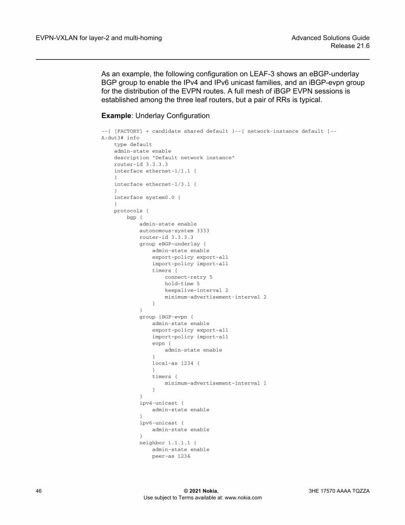
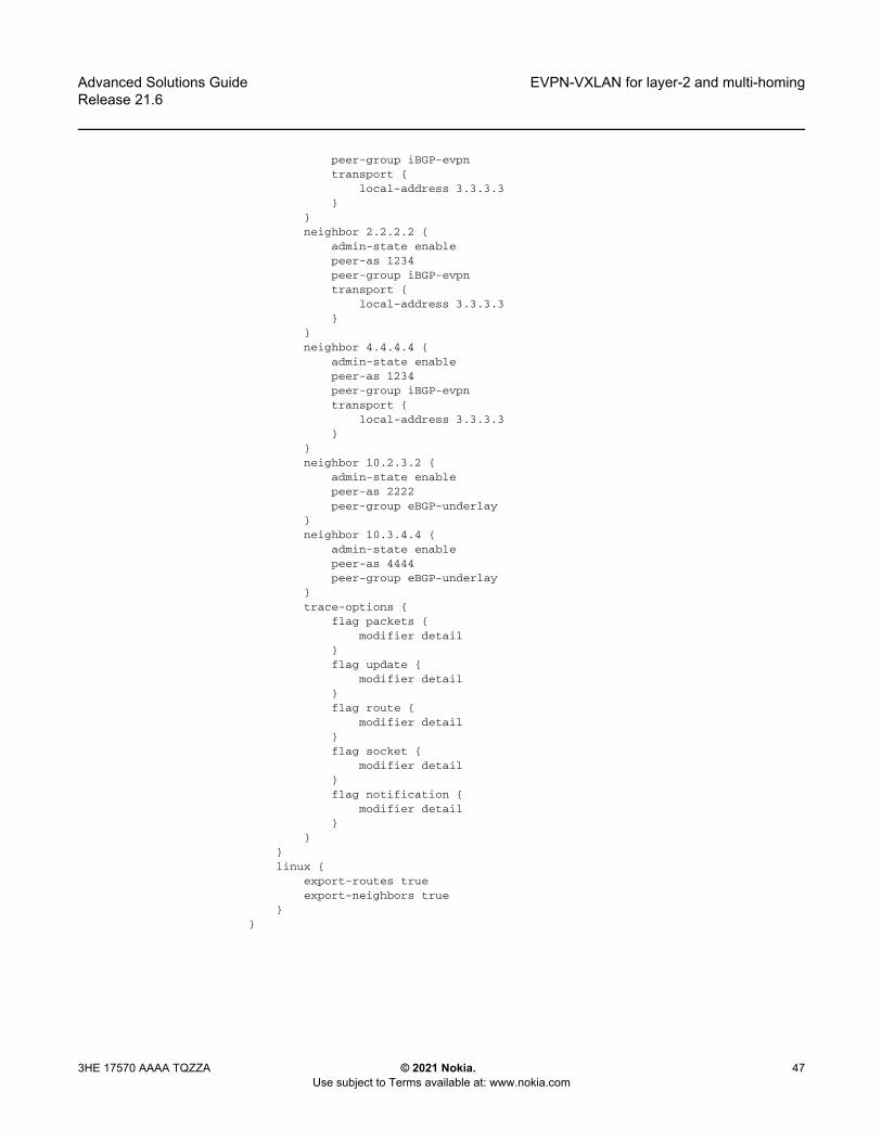
As an example, the following configuration on LEAF-3 shows an eBGP-underlay BGP group to enable the IPv4 and IPv6 unicast families, and an iBGP-evpn group for the distribution of the EVPN routes. A full mesh of iBGP EVPN sessions is established among the three leaf routers, but a pair of RRs is typical.

Example: Underlay Configuration

--{ [FACTORY] + candidate shared default }--[ network-instance default ]--A:dut3# info

type defaultadmin-state enabledescription "Default network instance"router-id 3.3.3.3interface ethernet-1/1.1 {}interface ethernet-1/3.1 {}interface system0.0 {}protocols {

bgp {admin-state enableautonomous-system 3333router-id 3.3.3.3group eBGP-underlay {

admin-state enableexport-policy export-allimport-policy import-alltimers {

connect-retry 5hold-time 5keepalive-interval 2minimum-advertisement-interval 2

}}group iBGP-evpn {

admin-state enableexport-policy export-allimport-policy import-allevpn {

admin-state enable}local-as 1234 {}timers {

minimum-advertisement-interval 1}

}ipv4-unicast {

admin-state enable}ipv6-unicast {

admin-state enable}neighbor 1.1.1.1 {

admin-state enablepeer-as 1234

Advanced Solutions GuideRelease 21.6

EVPN-VXLAN for layer-2 and multi-homing

3HE 17570 AAAA TQZZA © 2021 Nokia. Use subject to Terms available at: www.nokia.com

47

peer-group iBGP-evpntransport {

local-address 3.3.3.3}

}neighbor 2.2.2.2 {

admin-state enablepeer-as 1234peer-group iBGP-evpntransport {

local-address 3.3.3.3}

}neighbor 4.4.4.4 {

admin-state enablepeer-as 1234peer-group iBGP-evpntransport {

local-address 3.3.3.3}

}neighbor 10.2.3.2 {

admin-state enablepeer-as 2222peer-group eBGP-underlay

}neighbor 10.3.4.4 {

admin-state enablepeer-as 4444peer-group eBGP-underlay

}trace-options {

flag packets {modifier detail

}flag update {

modifier detail}flag route {

modifier detail}flag socket {

modifier detail}flag notification {

modifier detail}

}}linux {

export-routes trueexport-neighbors true

}}

EVPN-VXLAN for layer-2 and multi-homing

48

Advanced Solutions GuideRelease 21.6

© 2021 Nokia. Use subject to Terms available at: www.nokia.com

3HE 17570 AAAA TQZZA

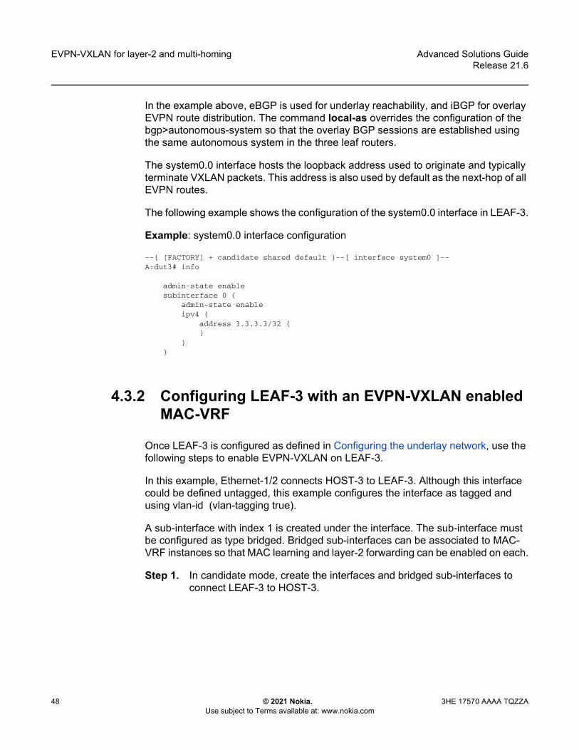
In the example above, eBGP is used for underlay reachability, and iBGP for overlay EVPN route distribution. The command local-as overrides the configuration of the bgp>autonomous-system so that the overlay BGP sessions are established using the same autonomous system in the three leaf routers.

The system0.0 interface hosts the loopback address used to originate and typically terminate VXLAN packets. This address is also used by default as the next-hop of all EVPN routes.

The following example shows the configuration of the system0.0 interface in LEAF-3.

Example: system0.0 interface configuration

--{ [FACTORY] + candidate shared default }--[ interface system0 ]--A:dut3# info

admin-state enablesubinterface 0 {

admin-state enableipv4 {

address 3.3.3.3/32 {}

}}

4.3.2 Configuring LEAF-3 with an EVPN-VXLAN enabled MAC-VRF

Once LEAF-3 is configured as defined in Configuring the underlay network, use the following steps to enable EVPN-VXLAN on LEAF-3.

In this example, Ethernet-1/2 connects HOST-3 to LEAF-3. Although this interface could be defined untagged, this example configures the interface as tagged and using vlan-id (vlan-tagging true).

A sub-interface with index 1 is created under the interface. The sub-interface must be configured as type bridged. Bridged sub-interfaces can be associated to MAC-VRF instances so that MAC learning and layer-2 forwarding can be enabled on each.

Step 1. In candidate mode, create the interfaces and bridged sub-interfaces to connect LEAF-3 to HOST-3.

Advanced Solutions GuideRelease 21.6

EVPN-VXLAN for layer-2 and multi-homing

3HE 17570 AAAA TQZZA © 2021 Nokia. Use subject to Terms available at: www.nokia.com

49

Example: creation of interfaces/bridged sub-interfaces--{ [FACTORY] + candidate shared default }--[ interface ethernet-1/2 ]--A:dut3# info

description dut3_host3admin-state enablevlan-tagging truesubinterface 1 {

type bridgedadmin-state enablevlan {

encap {single-tagged {

vlan-id 1}

}}

}

In the above example, the sub-interface uses vlan-id 1 since this is the VLAN id used by HOST-3 to send and receive frames. If you wanted HOST-3 to sent and received untagged traffic, the vlan encap command can be configured with either of these options:- vlan encap single-tagged vlan-id any - where 'any' captures all traffic

when no specific vlan-id has been defined. - vlan encap untagged - where 'untagged' captures traffic with no tags

or vlan-tag 0.Step 2. After creating the access sub-interfaces, create the vxlan-interfaces. This

allows MC-VRFs of the same BD to be connected throughout the IP fabric.The SR Linux models VXLAN as tunnels and vxlan-interfaces exist within them. The network-instance and main property is the VNI or VXLAN network identifier. SR Linux VXLAN model characteristics include:- The tunnel-interface for vxlan is configured as vxlan<N> where the

value of N is 0-255.- Multiple tunnel-interfaces can be configured. The tunnel-interface can

host multiple vxlan-interfaces.- vxlan-interfaces are configured under tunnel-interfaces with an

associated number in the range 0-4294967295. Minimally, the vxlan-interface must have an index, type, and ingress VNI.

- A vxlan-interface can only be associated to one network-instance, and in the R21.3, a network-instance can have only one vxlan-interface.

- The vxlan-interface type can be routed or bridged. When used for EVPN-VXLAN Layer-2 in MAC-VRFs, the type must be "bridged".

EVPN-VXLAN for layer-2 and multi-homing

50

Advanced Solutions GuideRelease 21.6

© 2021 Nokia. Use subject to Terms available at: www.nokia.com

3HE 17570 AAAA TQZZA

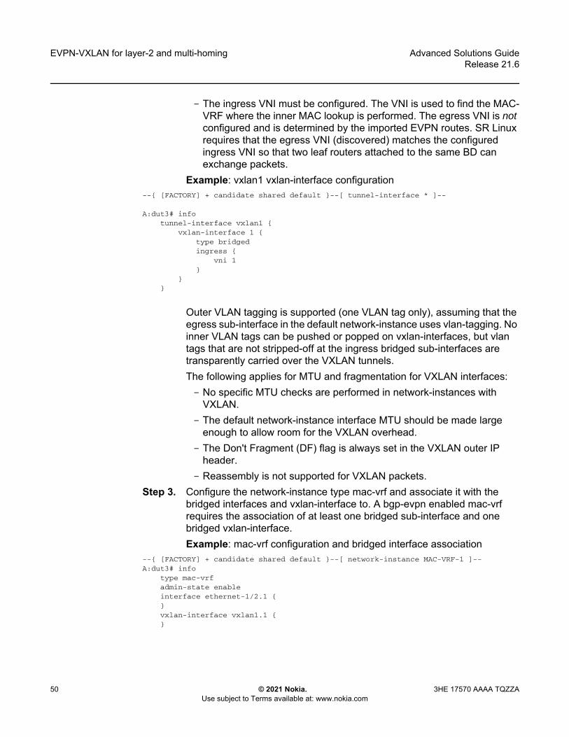
- The ingress VNI must be configured. The VNI is used to find the MAC-VRF where the inner MAC lookup is performed. The egress VNI is not configured and is determined by the imported EVPN routes. SR Linux requires that the egress VNI (discovered) matches the configured ingress VNI so that two leaf routers attached to the same BD can exchange packets.

Example: vxlan1 vxlan-interface configuration--{ [FACTORY] + candidate shared default }--[ tunnel-interface * ]--

A:dut3# infotunnel-interface vxlan1 {

vxlan-interface 1 {type bridgedingress {

vni 1}

}}

Outer VLAN tagging is supported (one VLAN tag only), assuming that the egress sub-interface in the default network-instance uses vlan-tagging. No inner VLAN tags can be pushed or popped on vxlan-interfaces, but vlan tags that are not stripped-off at the ingress bridged sub-interfaces are transparently carried over the VXLAN tunnels.The following applies for MTU and fragmentation for VXLAN interfaces:- No specific MTU checks are performed in network-instances with

VXLAN.- The default network-instance interface MTU should be made large

enough to allow room for the VXLAN overhead. - The Don't Fragment (DF) flag is always set in the VXLAN outer IP

header.- Reassembly is not supported for VXLAN packets.

Step 3. Configure the network-instance type mac-vrf and associate it with the bridged interfaces and vxlan-interface to. A bgp-evpn enabled mac-vrf requires the association of at least one bridged sub-interface and one bridged vxlan-interface.Example: mac-vrf configuration and bridged interface association

--{ [FACTORY] + candidate shared default }--[ network-instance MAC-VRF-1 ]--A:dut3# info

type mac-vrfadmin-state enableinterface ethernet-1/2.1 {}vxlan-interface vxlan1.1 {}

Advanced Solutions GuideRelease 21.6

EVPN-VXLAN for layer-2 and multi-homing

3HE 17570 AAAA TQZZA © 2021 Nokia. Use subject to Terms available at: www.nokia.com

51

Step 4. Enable EVPN in the mac-vrf by configuring the bgp-vpn and the bgp-evpn protocol containers:- bgp-vpn - Provides the configuration of the bgp-instances where the

route-distinguisher and the import/export route-targets used for the EVPN routes exist. Import and export policies can be used instead of explicit route-targets. In the current release, only one bgp-instance per network-instance is supported.

- bgp-evpn - Hosts all the commands required to enable EVPN in the network-instance. At a minimum, a reference to bgp-instance 1 is configured, along with the reference to the vxlan-interface (where EVPN is enabled) and the EVI. The EVI or EVPN Instance identifier is a two-byte value that is mandatory, and is used for:

• The auto-derivation of the route-distinguisher (RD). If a manual RD is not configured, the RD is auto-derived as system-ip:evi. Where the system-ip is the IP address configured in the system0.0 sub-interface.

• The auto-derivation of the route-target (RT). If a manual RT is not configured, the RT is auto-derived as autonomous-system:evi. The autonomous-system is configured in the default network-instance.

• The value used to represent the MAC-VRF in the DF Election algorithm. See Configuring multi-homing for EVPN broadcast domains

Example: Configure bgp-vpn and bgp-evpn protocol containers--{ [FACTORY] + candidate shared default }--[ network-instance MAC-VRF-1 ]--A:dut3# info

type mac-vrfadmin-state enableinterface ethernet-1/2.1 {}vxlan-interface vxlan1.1 {}protocols {

bgp-evpn {bgp-instance 1 {

admin-state enablevxlan-interface vxlan1.1evi 1ecmp 2

}}bgp-vpn {

bgp-instance 1 {route-target {

export-rt target:1234:1import-rt target:1234:1

}}

}}

EVPN-VXLAN for layer-2 and multi-homing

52

Advanced Solutions GuideRelease 21.6

© 2021 Nokia. Use subject to Terms available at: www.nokia.com

3HE 17570 AAAA TQZZA

Each leaf routers is configured with a different autonomous-system number. Therefore, EVI-based auto-derived RTs cannot be used or the three leaf routers would not produce the same import and export route-targets for the MAC-VRFs of the same BD. Therefore, RTs are configured manually.

Step 5. Review the changes. If correct, commit the changes.A:dut2# commit stay--{ candidate shared default }--[ ]--

4.3.3 Checking the EVPN-VXLAN operation in MAC-VRFs

Once all leaf routers attached to the same BD are configured, the state of the MAC-VRF and connectivity to LEAF-2 and LEAF-3 should be checked.

Example: Check vxlan-interface configuration

The following command checks that the vxlan-interface is properly configured and associated to the network-instance. If the network-instance vxlan-interface is oper-down, a reason is shown. The egress source-ip shown in the command should match the IPv4 address configured in the sub-interface system0.0.

--{ [FACTORY] + candidate shared default }--[ ]--A:dut3# show tunnel-interface vxlan1 vxlan-interface 1 brief---------------------------------------------------------------------------------Show report for vxlan-tunnels---------------------------------------------------------------------------------+------------------+-----------------+---------+-------------+------------------+| Tunnel Interface | VxLAN Interface | Type | Ingress VNI | Egress source-ip |+==================+=================+=========+=============+==================+| vxlan1 | vxlan1.1 | bridged | 1 | 3.3.3.3/32 |+------------------+-----------------+---------+-------------+------------------+--------------------------------------------------------------------------------Summary

1 tunnel-interfaces, 1 vxlan interfaces5 vxlan-destinations, 2 unicast, 1 es, 2 multicast, 0 ip

------------------------------------------------------------

A:dut3# show network-instance MAC-VRF-1 vxlan-interface vxlan1.1------------------------------------------------------------------------------------Show report for network instance "MAC-VRF-1" VxLAN interface table------------------------------------------------------------------------------------====================================================================================Network-instance: MAC-VRF-1VxLAN-Interface : vxlan1.1Type : bridgedOper state : upOper-down-reason: None====================================================================================

Advanced Solutions GuideRelease 21.6

EVPN-VXLAN for layer-2 and multi-homing

3HE 17570 AAAA TQZZA © 2021 Nokia. Use subject to Terms available at: www.nokia.com

53

Example: Check mac-vrf, bgp-vpn, and bgp-evpn parameters

The following command checks that the mac-vrf, bgp-vpn, and bgp-evpn parameters are properly configured. A manual or auto-derived RD/RT must exist, or the bgp-evpn bgp-instance will be oper-down.

A:dut3# show network-instance MAC-VRF-1 protocols bgp-vpn bgp-instance 1===================================================================================Net Instance : MAC-VRF-1

bgp Instance 1-----------------------------------------------------------------------------------

route-distinguisher: 3.3.3.3:1, auto-derived-from-eviexport-route-target: target:1234:1, manualimport-route-target: target:1234:1, manual

====================================================================================================================================================================--{ [FACTORY] + candidate shared default }--[ ]--A:dut3# show network-instance MAC-VRF-1 protocols bgp-evpn bgp-instance 1====================================================================================Net Instance : MAC-VRF-1

bgp Instance 1 is enabled and None------------------------------------------------------------------------------------

VXLAN-Interface : vxlan1.1evi : 1ecmp : 2default-admin-tag : 0oper-down-reason : N/AEVPN Routes

Next hop : NoneMAC/IP Routes : NoneIMET Routes : None, originating-ip None

====================================================================================--{ [FACTORY] + candidate shared default }--[ ]--

Example: Check VXLAN tunnels

This example checks for the creation of VXLAN tunnels to the remote VTEPs. After receiving EVPN routes from the remote leaf routers with VXLAN encapsulation, the vxlan_mgr creates VTEPs from the EVPN routes next-hops. Each VTEP gets an index allocated by fib_mgr (per source and destination tunnel IP addresses) if the next-hop is resolved in the default network-instance. The state of the two remote VTEPs is shown with their own indexes. EVPN routes are received with Next Hops 2.2.2.2 and 4.4.4.4 respectively.

--{ [FACTORY] + candidate shared default }--[ ]--A:dut3# show tunnel vxlan-tunnel all---------------------------------------------------------------------------------Show report for vxlan-tunnels--------------------------------------------------------------------------------+--------------+--------------+--------------------------+| VTEP Address | Index | Last Change |+==============+==============+==========================+| 2.2.2.2 | 278779228830 | 2021-02-15T11:07:23.000Z || 4.4.4.4 | 278779228829 | 2021-02-15T18:15:28.000Z |+--------------+--------------+--------------------------+

EVPN-VXLAN for layer-2 and multi-homing

54

Advanced Solutions GuideRelease 21.6

© 2021 Nokia. Use subject to Terms available at: www.nokia.com

3HE 17570 AAAA TQZZA

2 VXLAN tunnels, 2 active, 0 inactive-----------------------------------------------------------

Example: Check tunnel-table entries

The following command displays all tunnel-table entries. Once a VTEP is created in the vxlan-tunnel table and a non-zero index is allocated, a tunnel-table entry is created in the tunnel-table of the default network-instance.

If the next hop is not resolved to a route in the default network-instance route-table, the index in the vxlan-tunnel table shows as “0” for the VTEP and no tunnel-table is created. If the tunnel prefix in the tunnel-table is resolved, but the system runs out of hardware index resources, the tunnel will show in the tunnel-table, but will not be programmed. A non-programmed-reason will display.

--{ [FACTORY] + candidate shared default }--[ ]--A:dut3# show network-instance default tunnel-table all-------------------------------------------------------Show report for network instance "default" tunnel table------------------------------------------------------------------------------------------------------+-------------+-----------+-------+-------+--------+------------+----------+--------------------------+| IPv4 Prefix | Owner | Type | Index | Metric | Preference | Fib-prog | Last Update |+=============+===========+=======+=======+========+============+==========+==========================+| 2.2.2.2/32 | vxlan_mgr | vxlan | 4 | 0 | 0 | Y | 2021-03-01T10:41:38.590Z || 4.4.4.4/32 | vxlan_mgr | vxlan | 5 | 0 | 0 | Y | 2021-03-01T10:45:08.633Z |+-------------+-----------+-------+-------+--------+------------+----------+--------------------------+------------------------------------------------------------------------------------------------------2 VXLAN tunnels, 2 active, 0 inactive----------------------------------------------------------------------------------------------------------------------------------------------------------------------------------------------------------Show report for network instance "default" tunnel table-----------------------------------------------------------------------------------------------------

Example: Check statistics

Once the three leaf routers exchange packets over the VXLAN, LEAF-3 displays statistics for all individual VTEPs. Statistics include:

• Global-level ingress/egress packets and octets. Global in/out octets and packets are aggregations of the individual statistics per VTEP. “in-discarded-packets” are vxlan packets discarded due to a non-existent local VNI, packets from a source VTEP are not discovered in the control plan, and packets are not aggregations of individual per VTEP dropped packets

• Per VTEP packets and octets with in/out discarded packets.--{ [FACTORY] + candidate shared default }--[ ]--A:dut3# info from state tunnel vxlan-tunnel

tunnel {vxlan-tunnel {

vtep 2.2.2.2 {index 278779228830last-change "8 hours ago"

Advanced Solutions GuideRelease 21.6

EVPN-VXLAN for layer-2 and multi-homing

3HE 17570 AAAA TQZZA © 2021 Nokia. Use subject to Terms available at: www.nokia.com

55

statistics {in-octets 0in-packets 0in-discarded-packets 0out-octets 0out-packets 0out-discarded-packets 0

}}vtep 4.4.4.4 {

index 278779228829last-change "an hour ago"statistics {

in-octets 555720in-packets 5052in-discarded-packets 0out-octets 0out-packets 0out-discarded-packets 0

}}statistics {

in-octets 555720in-packets 5052in-discarded-packets 0out-octets 0out-packets 0

}}

}

Statistics can be cleared using the command: tools tunnel vxlan-tunnel vtep 2.2.2.2 statistics clear

Example: Check for received IMET routes and multicast destination creation

IMET routes are used for auto-discovery and the creation of the default flood list for vxlan in the MAC-VRF. When LEAF-3 receives and imports the IMET routes from LEAF-2 and LEAF-4, it creates a VXLAN default flood list. BUM frames received on a bridged sub-interface are ingress-replicated to the VTEPs on the list.

The following command checks that the IMET routes for the BD from LEAF-2 and LEAF-4 have been received and they have created multicast destinations in the MAC-VRF. Note that the VNI is received in the PMSI tunnel attribute and not in the route’s Network Layer Reachability Information (NLRI).

--{ [FACTORY] + candidate shared default }--[ ]--A:dut3# show network-instance default protocols bgp routes evpn route-type 3 detail------------------------------------------------------------------------------------Show report for the EVPN routes to network "*" network-instance "default"------------------------------------------------------------------------------------Route Distinguisher: 2.2.2.2:1Tag-ID : 0Originating router : 2.2.2.2neighbor : 2.2.2.2

EVPN-VXLAN for layer-2 and multi-homing

56

Advanced Solutions GuideRelease 21.6

© 2021 Nokia. Use subject to Terms available at: www.nokia.com

3HE 17570 AAAA TQZZA

Received paths : 1Path 1: <Best,Valid,Used,>

VNI : 1Route source : neighbor 2.2.2.2 (last modified 9h11m44s ago)Route preference: No MED, LocalPref is 100Atomic Aggr : falseBGP next-hop : 2.2.2.2AS Path : iCommunities : [target:1234:1, bgp-tunnel-encap:VXLAN]RR Attributes : No Originator-ID, Cluster-List is []Aggregation : NoneUnknown Attr : NoneInvalid Reason : NoneTie Break Reason: none

------------------------------------------------------------------------------------Route Distinguisher: 4.4.4.4:1Tag-ID : 0Originating router : 4.4.4.4neighbor : 4.4.4.4Received paths : 1

Path 1: <Best,Valid,Used,>VNI : 1Route source : neighbor 4.4.4.4 (last modified 9h11m44s ago)Route preference: No MED, LocalPref is 100Atomic Aggr : falseBGP next-hop : 4.4.4.4AS Path : iCommunities : [target:1234:1, bgp-tunnel-encap:VXLAN]RR Attributes : No Originator-ID, Cluster-List is []Aggregation : NoneUnknown Attr : NoneInvalid Reason : NoneTie Break Reason: none

--------------------------------------------------------------------------------------{ [FACTORY] + candidate shared default }--[ ]----{ [FACTORY] + candidate shared default }--[ ]--A:dut3# info from state network-instance default bgp-rib evpn rib-in-out rib-in-post imet-routes * originating-router * ethernet-tag-id * neighbor *

network-instance default {bgp-rib {

evpn {rib-in-out {

rib-in-post {imet-routes 2.2.2.2:1 originating-router 2.2.2.2 ethernet-

tag-id 0 neighbor 2.2.2.2 {attr-id 193last-modified 2021-02-15T11:07:21.500Zused-route truevalid-route truebest-route truestale-route falsepending-delete falsetie-break-reason noneinvalid-reason {

rejected-route falseas-loop falsenext-hop-unresolved falsecluster-loop false

}

Advanced Solutions GuideRelease 21.6

EVPN-VXLAN for layer-2 and multi-homing

3HE 17570 AAAA TQZZA © 2021 Nokia. Use subject to Terms available at: www.nokia.com

57

}imet-routes 4.4.4.4:1 originating-router 4.4.4.4 ethernet-

tag-id 0 neighbor 4.4.4.4 {attr-id 197last-modified 2021-02-15T11:07:21.500Zused-route truevalid-route truebest-route truestale-route falsepending-delete falsetie-break-reason noneinvalid-reason {

rejected-route falseas-loop falsenext-hop-unresolved falsecluster-loop false

}}

}}

}}

}--{ [FACTORY] + candidate shared default }--[ ]--A:dut3# info from state network-instance default bgp-rib attr-sets attr-set rib-in index {193,197}

network-instance default {bgp-rib {

attr-sets {attr-set rib-in index 193 {

origin igpatomic-aggregate falsenext-hop 2.2.2.2med 0local-pref 100aggregator {}pmsi-tunnel {

tunnel-type ingress-replicationvni 1tunnel-endpoint 2.2.2.2

}communities {

ext-community [target:1234:1bgp-tunnel-encap:VXLAN

]}unknown-attributes {}

}attr-set rib-in index 197 {

origin igpatomic-aggregate falsenext-hop 4.4.4.4med 0local-pref 100aggregator {}

EVPN-VXLAN for layer-2 and multi-homing

58

Advanced Solutions GuideRelease 21.6

© 2021 Nokia. Use subject to Terms available at: www.nokia.com

3HE 17570 AAAA TQZZA

pmsi-tunnel {tunnel-type ingress-replicationvni 1tunnel-endpoint 4.4.4.4

}communities {

ext-community [target:1234:1bgp-tunnel-encap:VXLAN

]}unknown-attributes {}

}}

}}

Example: Check for multicast-destinations

If the IMET routes from LEAF-2 and LEAF-4 are imported for MAC-VRF-1, the corresponding multicast VXLAN destinations are added and can be checked with the following command:

--{ [FACTORY] + candidate shared default }--[ ]--A:dut3# show tunnel-interface vxlan1 vxlan-interface 1 bridge-table multicast-destinations destination *------------------------------------------------------------------------------------Show report for vxlan-interface vxlan1.1 multicast destinations (flooding-list)------------------------------------------------------------------------------------+--------------+------------+-------------------+----------------------+| VTEP Address | Egress VNI | Destination-index | Multicast-forwarding |+==============+============+===================+======================+| 2.2.2.2 | 1 | 278779228840 | BUM || 4.4.4.4 | 1 | 278779228838 | BUM |+--------------+------------+-------------------+----------------------+------------------------------------------------------------------------Summary

2 multicast-destinations--------------------------------------------------------------------------------------{ [FACTORY] + candidate shared default }--[ ]--

Example: Check mac-table and MAC/IP routes

When traffic is exchanged between HOST-3 and HOST-12, the MACs are learned on the access bridged sub-interfaces and advertised in MAC/IP routes. The MAC/IP routes are imported, and the MACs programmed in the mac-table. The following command can check the MAC/IP routes and the programmed MACs.

--{ [FACTORY] + candidate shared default )--[ ]--A:dut3# show network-instance MAC-VRF-1 bridge-table mac-table all-----------------------------------------------------------------------------------------------------Mac-table of network instance MAC-VRF-1-----------------------------------------------------------------------------------------------------+--------------+---------------------------+------------+------+--------+-------+-------------------+

Advanced Solutions GuideRelease 21.6

EVPN-VXLAN for layer-2 and multi-homing

3HE 17570 AAAA TQZZA © 2021 Nokia. Use subject to Terms available at: www.nokia.com

59

| Address | Destination | Dest Index | Type | Active | Aging | Last Update |+==============+===========================+============+======+========+=======+===================+| 00:00:00:00: | vxlan-interface:vxlan1.1 | 2787792288 | evpn | true | N/A | 2021-02-16T10:54: || 00:01 | esi:01:24:24:24:24:24:24: | 46 | | | | 54.000Z || | 00:00:01 | | | | | || 00:00:00:00: | vxlan-interface:vxlan1.1 | 2787792288 | evpn | true | N/A | 2021-02-16T10:54: || 00:02 | vtep:2.2.2.2 vni:1 | 40 | | | | 54.000Z || 00:00:00:00: | ethernet-1/2.1 | 12 |learnt| true | 300 | 2021-02-16T10:54: || 00:03 | | | | | | 54.000Z || 00:00:00:00: | vxlan-interface:vxlan1.1 | 2787792288 | evpn | true | N/A | 2021-02-16T10:54: || 00:04 | vtep:4.4.4.4 vni:1 | 38 | | | | 54.000Z |+--------------+---------------------------+------------+------+--------+-------+-------------------+Total Irb Macs : 0 Total 0 ActiveTotal Static Macs : 0 Total 0 ActiveTotal Duplicate Macs : 0 Total 0 ActiveTotal Learnt Macs : 1 Total 1 ActiveTotal Evpn Macs : 3 Total 3 ActiveTotal Irb anycast Macs : 0 Total 0 ActiveTotal Macs : 4 Total 4 Active-----------------------------------------------------------------------------------------------------{ [FACTORY] + candidate shared default }--[ ]--

A:dut3# show network-instance default protocols bgp routes evpn route-type 2 summary------------------------------------------------------------------------------------Show report for the BGP route table of network-instance "default"------------------------------------------------------------------------------------Status codes: u=used, *=valid, >=best, x=staleOrigin codes: i=IGP, e=EGP, ?=incomplete-----------------------------------------------------------------------------------BGP Router ID: 3.3.3.3 AS: 3333 Local AS: 3333-----------------------------------------------------------------------------------Type 2 MAC-IP Advertisement Routes+--------+-----------+-----+--------------+---------+---------+---------+----+-------------------+------+| Status | Route-dis-| Tag | MAC-address | IP- | Neighbor| Next- | VNI| ESI | MAC || | tinguisher| ID | | address | | Hop | | | Mob. |+========+===========+=====+==============+=========+=========+=========+====+===================+======+| u*> | 2.2.2.2:1 | 0 | 00:00:00:00: | 0.0.0.0 | 2.2.2.2 | 2.2.2.2 | 1 | 00:00:00:00:00:00 | - || | | | 00:02 | | | | | 00:00:00:00 | || u*> | 4.4.4.4:1 | 0 | 00:00:00:00: | 0.0.0.0 | 4.4.4.4 | 4.4.4.4 | 1 | 01:24:24:24:24:24 | - || | | | 00:01 | | | | | 24:00:00:01 | || u*> | 4.4.4.4:1 | 0 | 00:00:00:00: | 0.0.0.0 | 4.4.4.4 | 4.4.4.4 | 1 | 00:00:00:00:00:00:| - || | | | 00:04 | | | | | 00:00:00:0 0 | |+--------+-----------+-----+--------------+---------+---------+---------+----+-------------------+------+---------------------------------------------------------------------------------------------------------3 MAC-IP Advertisement routes 3 used, 3 valid----------------------------------------------------------------------------------------------------------{ [FACTORY] + candidate shared default }--[ ]--

EVPN-VXLAN for layer-2 and multi-homing

60

Advanced Solutions GuideRelease 21.6

© 2021 Nokia. Use subject to Terms available at: www.nokia.com

3HE 17570 AAAA TQZZA

Example: Check unicast destinations

The reception of MAC/IP routes also creates unicast destinations in the vxlan-interface. In some cases, the unicast destinations are Ethernet Segment (ES) destinations if the MAC/IP routes are advertised from an ES. See Configuring multi-homing for EVPN broadcast domains for details. The following command displays the unicast destinations.

--{ [FACTORY] + candidate shared default }--[ ]--A:dut3# show tunnel-interface vxlan1 vxlan-interface 1 bridge-table unicast-destinations destination *-----------------------------------------------------------------------------------------------------Show report for vxlan-interface vxlan1.1 unicast destinations----------------------------------------------------------------------------------------------------Destinations-------------------------------------------------------------------------------+--------------+------------+-------------------+-----------------------------+| VTEP Address | Egress VNI | Destination-index | Number MACs (Active/Failed) |+==============+============+===================+=============================+| 2.2.2.2 | 1 | 278779228840 | 1(1/0) || 4.4.4.4 | 1 | 278779228838 | 1(1/0) |+--------------+------------+-------------------+-----------------------------+-------------------------------------------------------------------------------Ethernet Segment Destinations------------------------------------------------------------------------------------------------------+-------------------------------+-------------------+------------------+-----------------------------+| ESI | Destination-index | VTEPs | Number MACs (Active/Failed) |+===============================+===================+==================+=============================+| 01:24:24:24:24:24:24:00:00:01 | | 2.2.2.2, 4.4.4.4 | 0(0/0) |+-------------------------------+-------------------+------------------+-----------------------------+------------------------------------------------------------------------------------------------------Summary

3 unicast-destinations, 2 non-es, 1 es2 MAC addresses, 2 active, 0 non-active

-------------------------------------------------------------------------------------------------------{ [FACTORY] + candidate shared default }--[ ]--

4.3.4 Checking MAC mobility, MAC protection and MAC loop protection in EVPN-VXLAN BDs

MAC mobility and MAC protection are implemented following [RFC7432]. MAC loop protection follows [draft-ietf-bess-rfc7432bis].

Advanced Solutions GuideRelease 21.6

EVPN-VXLAN for layer-2 and multi-homing

3HE 17570 AAAA TQZZA © 2021 Nokia. Use subject to Terms available at: www.nokia.com

61

4.3.4.1 MAC mobility

MAC Mobility is an event that triggers the fast move and re-learn of a MAC in a different leaf router. Mobility is common in DCs with some workloads moving between racks in the same DC. EVPN provides tools for fast mobility since MAC/IP routes are advertised with a sequence number that indicates the latest location of a MAC. This sequence number is used by the leaf routers to program the MAC with the correct VXLAN destination.

Example: MAC mobility (1 of 2)

Using Figure 6 as reference, if HOST-2 moves from LEAF-2 to LEAF-3, and you review the programming of the MAC in LEAF-4, MAC 00:00:00:00:00:02 is learned against VXLAN destination vtep:2.2.2.2 vni:1:

--{ [FACTORY] + candidate shared default }--[ network-instance MAC-VRF-1 bridge-table ]--A:dut4# /show network-instance MAC-VRF-1 bridge-table mac-table all-----------------------------------------------------------------------------------------------------Mac-table of network i---------------------------------------------------------------------------------------------------+--------------------+--------------------------+------------+-------+--------+-------+---------------+| Address | Destination | Dest Index | Type | Active | Aging | Last Update |+====================+==========================+============+=======+========+=======+===============+| 00:00:00:00:00:01 | lag1.1 | 11 | learnt| true | 300 | 2021-02-16T11:|| | | | | | | 32:14.000Z |

| 00:00:00:00:00:02 | vxlan-interface:vxlan1.1 | 2787793311 | evpn | true | N/A | 2021-02-16T11:|| | vtep:2.2.2.2 vni:1 | 82 | | | | 32:15.000z || 00:00:00:00:00:03 | vxlan-interface:vxlan1.1 | 2787793311 | evpn | true | N/A | 2021-02-16T11:|| | vtep:3.3.3.3 vni:1 | 84 | | | | 32:15.000Z || 00:00:00:00:00:04 | ethernet-1/13.1 | 13 | learnt| true | 300 | 2021-02-16T11:|| | | | | | | 32:14.000Z || 00:CA:FE:CA:FE:04 | ethernet-1/13.1 | 13 | static| true | N/A | 2021-02-16T11:|| | | | | | | 10:26.000Z |+--------------------+--------------------------+------------+-------+--------+-------+---------------+Total Irb Macs : 0 Total 0 ActiveTotal Static Macs : 1 Total 1 ActiveTotal Duplicate Macs : 0 Total 0 ActiveTotal Learnt Macs : 2 Total 2 ActiveTotal Evpn Macs : 2 Total 2 ActiveTotal Evpn static Macs : 0 Total 0 ActiveTotal Irb anycast Macs : 0 Total 0 ActiveTotal Macs : 5 Total 5 Active------------------------------------------------------------------------------------------------------

EVPN-VXLAN for layer-2 and multi-homing

62

Advanced Solutions GuideRelease 21.6

© 2021 Nokia. Use subject to Terms available at: www.nokia.com

3HE 17570 AAAA TQZZA

Example: MAC mobility (2 of 2)

After the mobility event, LEAF-4 receives the MAC with a higher sequence number. This makes LEAF-4 reprogram the MAC against LEAF-3 as shown below:

2021-02-16T03:33:53.505253-08:00 dut4 local6|DEBU sr_bgp_mgr: bgp|4959|5178|402506|D:VR default (1) Peer 1: 3.3.3.3 UPDATE: Peer 1: 3.3.3.3 - Received BGP UPDATE:

Withdrawn Length = 0Total Path Attr Length = 96Flag: 0x90 Type: 14 Len: 44 Multiprotocol Reachable NLRI:

Address Family EVPNNextHop len 4 NextHop 3.3.3.3Type: EVPN-MAC Len: 33 RD: 3.3.3.3:1 ESI: ESI-0, tag: 0, mac len: 48 mac: 00:00:00:00:00:02,

IP len: 0, IP: NULL, label1: 1Flag: 0x40 Type: 1 Len: 1 Origin: 0Flag: 0x40 Type: 2 Len: 0 AS Path:Flag: 0x80 Type: 4 Len: 4 MED: 0Flag: 0x40 Type: 5 Len: 4 Local Preference: 100Flag: 0xc0 Type: 16 Len: 24 Extended Community:

target:1234:1bgp-tunnel-encap:VXLANmac-mobility:Seq:1

--{ [FACTORY] + candidate shared default }--[ ]--

A:dut4# show network-instance MAC-VRF-1 bridge-table mac-table all--------------------------------------------------------------------------------------------------------Mac-table of network instance MAC-VRF-1---------------------------------------------------------------------------------------------------------+--------------------+--------------------------+------------+-------+--------+--------+----------------+| Address | Destination | Dest Index | Type | Active | Aging | Last Update |+====================+==========================+============+=======+========+========+================+| 00:00:00:00:00:01 | lag1.1 | 11 | learnt| true | 180 | 2021-02-16T11: || | | | | | | 32:14.000Z || 00:00:00:00:00:02 | vxlan-interface:vxlan1.1 | 2787793311 | evpn | true | N/A | 2021-02-16T11: || | vtep:3.3.3.3 vni:1 | 84 | | | | 33:54.000Z || 00:00:00:00:00:03 | vxlan-interface:vxlan1.1 | 2787793311 | evpn | true | N/A | 2021-02-16T11: || | vtep:3.3.3.3 vni:1 | 84 | | | | 32:15.000Z || 00:00:00:00:00:04 | ethernet-1/13.1 | 13 | learnt| true | 180 | 2021-02-16T11: || | | | | | | 32:14.000Z || 00:CA:FE:CA:FE:04 | ethernet-1/13.1 | 13 | static| true | N/A | 2021-02-16T11: || | | | | | | 10:26.000Z |+--------------------+--------------------------+------------+-------+--------+--------+----------------+Total Irb Macs : 0 Total 0 ActiveTotal Static Macs : 1 Total 1 ActiveTotal Duplicate Macs : 0 Total 0 ActiveTotal Learnt Macs : 2 Total 2 ActiveTotal Evpn Macs : 3 Total 3 ActiveTotal Evpn static Macs : 0 Total 0 ActiveTotal Irb anycast Macs : 0 Total 0 ActiveTotal Macs : 5 Total 5 Active

----------------------------------------------------------------------------------------------------------{ [FACTORY] + candidate shared default }--[ ]--

Advanced Solutions GuideRelease 21.6

EVPN-VXLAN for layer-2 and multi-homing

3HE 17570 AAAA TQZZA © 2021 Nokia. Use subject to Terms available at: www.nokia.com

63

4.3.4.2 MAC protection

MAC protection refers to the property of a MAC that does not move between leaf routers. It is always learned against a bridged sub-interface. You can configure this MAC as static, but should observe the following:

• When a MAC is programmed as static, the same MAC cannot be learned in another sub-interace or via EVPN. If frames arriving on an interface are different than the ones associated to the static MAC, they are discarded.

• The MAC is now advertised as “static” in EVPN and installed as "evpn-static" in the leaf routers attached to the same BD. If programmed, evpn-static MACs are also protected. Therefore, frames arriving on a local sub-interface are discarded if their source MAC matches an evpn-static MAC.

Example: MAC protection (1 of 2)

Using Figure 6 as reference, the following commands show MAC 00:ca:fe:ca:fe:04 is configured as static in LEAF-4.

--{ [FACTORY] +* candidate shared default }--[ network-instance MAC-VRF-1 bridge-table ]--A:dut4# info

static-mac {mac 00:CA:FE:CA:FE:04 {

destination ethernet-1/13.1}

}--{ [FACTORY] +* candidate shared default }--[ network-instance MAC-VRF-1 bridge-table ]--A:dut4# commit stayAll changes have been committed. Starting new transaction.--{ [FACTORY] + candidate shared default }--[ network-instance MAC-VRF-1 bridge-table ]--A:dut4#--{ [FACTORY] + candidate shared default }--[ network-instance MAC-VRF-1 bridge-table ]--A:dut4# /show network-instance MAC-VRF-1 bridge-table mac-table all-----------------------------------------------------------------------------------------Mac-table of network instance MAC-VRF-1--------------------------------------------------------------------------------------------+--------------+--------------------------+------------+-------+--------+-------+-------------------+| Address | Destination | Dest Index | Type | Active | Aging | Last Update |+==============+==========================+============+=======+========+=======+===================+| 00:00:00:00: | lag1.1 | 11 | learnt| true | 180 | 2021-02-16T11:08: || 00:01 | | | | | | 10.000Z || 00:00:00:00: | vxlan-interface:vxlan1.1 | 2787793311 | evpn | true | N/A | 2021-02-16T11:08: || 00:02 | vtep:2.2.2.2 vni:1 | 82 | | | | 11.000Z || 00:00:00:00: | vxlan-interface:vxlan1.1 | 2787793311 | evpn | true | N/A | 2021-02-16T11:08: || 00:03 | vtep:3.3.3.3 vni:1 | 84 | | | | 11.000Z || 00:00:00:00: | ethernet-1/13.1 | 13 | learnt| true | 180 | 2021-02-16T11:08: || 00:04 | | | | | | 10.000Z || 00:CA:FE:CA: | ethernet-1/13.1 | 13 | static| true | N/A | 2021-02-16T11:10: || FE:04 | | | | | | 26.000Z |+--------------+--------------------------+------------+-------+--------+-------+-------------------+Total Irb Macs : 0 Total 0 ActiveTotal Static Macs : 1 Total 1 ActiveTotal Duplicate Macs : 0 Total 0 Active

EVPN-VXLAN for layer-2 and multi-homing

64

Advanced Solutions GuideRelease 21.6

© 2021 Nokia. Use subject to Terms available at: www.nokia.com

3HE 17570 AAAA TQZZA

Total Learnt Macs : 2 Total 2 ActiveTotal Evpn Macs : 2 Total 2 ActiveTotal Evpn static Macs : 0 Total 0 ActiveTotal Irb anycast Macs : 0 Total 0 ActiveTotal Macs : 5 Total 5 Active-----------------------------------------------------------------------------------------------------{ [FACTORY] + candidate shared default }--[ network-instance MAC-VRF-1 bridge-table ]--

Example: MAC protection (2 of 2

On the remote leaf routers, the MAC is received as evpn-static and programmed this way. For example, LEAF-4 receives the route and programs it as follows:

2021-02-16T03:10:27.402653-08:00 dut3 local6|DEBU sr_bgp_mgr: bgp|4628|4789|270039|D:VR default (1) Peer 1: 4.4.4.4 UPDATE: Peer 1: 4.4.4.4 - Received BGP UPDATE:

Withdrawn Length = 0Total Path Attr Length = 96Flag: 0x90 Type: 14 Len: 44 Multiprotocol Reachable NLRI:

Address Family EVPNNextHop len 4 NextHop 4.4.4.4Type: EVPN-MAC Len: 33 RD: 4.4.4.4:1 ESI: ESI-0, tag: 0, mac len: 48 mac:

00:ca:fe:ca:fe:04, IP len: 0, IP: NULL, label1: 1Flag: 0x40 Type: 1 Len: 1 Origin: 0Flag: 0x40 Type: 2 Len: 0 AS Path:Flag: 0x80 Type: 4 Len: 4 MED: 0Flag: 0x40 Type: 5 Len: 4 Local Preference: 100Flag: 0xc0 Type: 16 Len: 24 Extended Community:

target:1234:1bgp-tunnel-encap:VXLANmac-mobility:Seq:0/Static

--{ [FACTORY] + candidate shared default }--[ ]--A:dut3# show network-instance MAC-VRF-1 bridge-table mac-table all-------------------------------------------------------------------------------------------------------Mac-table of network instance MAC-VRF-1-------------------------------------------------------------------------------------------------------+---------------+--------------------------+------------+------------+-------+-------+----------------+| Address | Destination | Dest Index | Type | Active| Aging | Last Update |+===============+==========================+============+============+=======+=======+================+| 00:CA:FE:CA: | vxlan-interface:vxlan1.1 | 2787792288 | evpn-static| true | N/A | 2021-02-16T11: || FE:04 | vtep:4.4.4.4 vni:1 | 38 | | | | 10:27.000Z |+---------------+--------------------------+------------+------------+-------+-------+----------------+Total Irb Macs : 0 Total 0 ActiveTotal Static Macs : 0 Total 0 ActiveTotal Duplicate Macs : 0 Total 0 ActiveTotal Learnt Macs : 0 Total 0 ActiveTotal Evpn Macs : 0 Total 0 ActiveTotal Evpn static Macs : 1 Total 1 ActiveTotal Irb anycast Macs : 0 Total 0 ActiveTotal Macs : 1 Total 1 Active-------------------------------------------------------------------------------------------------------{ [FACTORY] + candidate shared default }--[

Advanced Solutions GuideRelease 21.6

EVPN-VXLAN for layer-2 and multi-homing

3HE 17570 AAAA TQZZA © 2021 Nokia. Use subject to Terms available at: www.nokia.com

65

Note that the static MACs state depends on the state of the sub-interface which they are configured against. If the sub-interface goes oper-down, the static MAC and EVPN route are removed. Static Blackhole MACs (where the configured destination is "blackhole") also behave as static MACs and are advertised as "evpn-static".

4.3.4.3 MAC loop protection

MAC loop protection in EVPN BDs is based on the SR Linux MAC Duplication feature. This feature detects MAC duplication for MACs moving:

• among bridge sub-interfaces of the same MAC-VRF• between bridge sub-interfaces and EVPN (in the same MAC-VRF)

It does not detect MAC duplication for MACs moving from one VTEP to a different VTEP in the same MAC-VRF. In addition, when a MAC is declared as a duplicate:

• If the blackhole configuration option is added to the interface, incoming frames on bridged sub-interfaces are discarded if their MAC SA or DA match the blackhole MAC. Frames encapsulated in VXLAN packets are discarded if their inner source MAC or destination MAC match the blackhole MAC in the mac-table.

• The "duplicate" MAC can be overwritten by a higher priority type (for example, static or evpn-static) or flushed by a tools command. Blackhole MACs that result out of duplicate MACs are advertised as regular MACs (non-static).

4.4 Configuring multi-homing for EVPN broadcast domains

SR Linux supports all-active multi-homing for multi-homed peers connected using VXLAN, as per [RFC8365].

Using Figure 6 as a reference, LEAF-2 and LEAF-3 are multi-homed to server-1 using all-active multi-homing. The representation of the multi-homed device in the EVPN control plane is referred to as an Ethernet Segment (ES). It is considered "all-active" and not "active-active", because SR Linux supports up to four leaf routers multi-homed to the same CE or server with all links being active (not just two).

The all-active multi-homing function relies on three different procedures to handle multi-homing in the ES:

EVPN-VXLAN for layer-2 and multi-homing

66

Advanced Solutions GuideRelease 21.6

© 2021 Nokia. Use subject to Terms available at: www.nokia.com

3HE 17570 AAAA TQZZA

• Designated Forwarder (DF) election• Split-Horizon (also known as Local-Bias) • Aliasing

The DF is the leaf that forwards BUM traffic received from the VXLAN into the ES (to the server). Only one DF can exist per ES at a time, and it is elected based on the exchange of ES routes (EVPN routes type 4) and the subsequent DF election algorithm. All leaf routers, DF and non-DF, will forward known-unicast traffic to the multi-homed server.

The split-horizon or local bias is the procedure that avoids looped packets on the server. If server-1 hashes the BUM traffic to the non-DF leaf (for example, LEAF-2), without any split-horizon technique, the flooded BUM packets move to the DF (LEAF-4) and back to server-1. Split-horizon prevents these flooded packets from forwarding back to server-1. When the data plane is VXLAN, the split-horizon mechanism is based on a "local-bias" forwarding mode as defined in RFC8365. This implies that:

• BUM traffic from a local sub-interface is always forwarded to the ES, irrespective of the PE being DF. For example, if HOST-2 sends a broadcast frame, it will be sent to the ES (lag1.1) even though LEAF- is non-DF for ES-1.

• BUM traffic received over VXLAN is never be forwarded to the ES if the source VTEP matches a leaf that is attached to the same ES. For example, BUM traffic from HOST-2 that is forwarded via VXLAN to LEAF-4 will not be forwarded to lag1.1, only to Ethernet-1/13.1.

Aliasing is the procedure that allows ecmp (load-balancing) from remote leaf routers (LEAF-3) to all leaf routers attached to the same ES, even though the MAC is only advertised by one of the leaf routers in the ES. For example, in Figure 6, flows from 00:00:00:00:00:01 can only be hashed to LEAF-2. LEAF-2 is the only router in the ES advertising the MAC. However, since LEAF-2 and LEAF-4 advertise the association to the same Ethernet Segment Identifier (ESI), and the MAC/IP route for 00:00:00:00:00:01 is tagged with ESI-1, LEAF-3 can "alias" the unicast traffic to both leaf routers.

Note that a leaf advertises its association to an ES via AD per ES routes, and its association to an ES for a given MAC-VRF via AD per EVI routes. Both are EVPN routes type 1.

Advanced Solutions GuideRelease 21.6

EVPN-VXLAN for layer-2 and multi-homing

3HE 17570 AAAA TQZZA © 2021 Nokia. Use subject to Terms available at: www.nokia.com

67

4.4.1 All-active multi-homing configurations

Configuration of all-active multi-homing involves four major steps:

• Configuring the server/CE with a single LAG that connects it to the leaf routers.• Configuring an ES (ES-1) on the leaf routers (LEAF-2 and LEAF-4)• Associating the ES interface with the MAC-VRF.• Optional: Configuring the ecmp with a value greater than 1 in all the leaf routers

attached to the same BD (for aliasing). This step is only required if multi-homing is used in an EVPN-VXLAN BD distributed among multiple leaf routers.

4.4.1.1 Ethernet segment configuration details

With SR Linux, ESs are control plane entities that reside in the system network-instance. The system network-instance contains a BGP-VPN instance similar to the one in mac-vrfs. This instance hosts the bgp information used by EVPN for multi-homing routes, and the ES configuration and state.

The following example provides ES configuration details.

--{ [FACTORY] + candidate shared default }--[ system network-instance protocols evpn ethernet-segments ]--

A:dut4# tree detailethernet-segments!+ evpn_mgr+-- timers evpn_mgr| +-- boot-timer? evpn_mgr| +-- activation-timer? evpn_mgr+-- bgp-instance* [id] evpn_mgr

+-- ethernet-segment* [name] evpn_mgr+-- admin-state? evpn_mgr+-- esi? evpn_mgr+-- interface? evpn_mgr+-- multi-homing-mode? evpn_mgr+-- df-election evpn_mgr| +-- timers evpn_mgr| | +-- activation-timer? evpn_mgr

The ES model uses a BGP-VPN instance where the route-distinguisher and export/import route-targets are taken by BGP and used for the ES routes. Only one instance is allowed, and all ESs live under this BGP instance. The default route-distinguisher for the instance is automatically derived from system-ip:0 and used in ES routes.

The default import/export route-target is automatically derived from the ESI (bytes 1 to 6; from the second highest order byte up to the seventh byte). This route-target is of type ESI-import route-target (as per [RFC7432]) and is used in ES routes to ensure they are imported on Leaf routers attached to the ES.

EVPN-VXLAN for layer-2 and multi-homing

68

Advanced Solutions GuideRelease 21.6

© 2021 Nokia. Use subject to Terms available at: www.nokia.com

3HE 17570 AAAA TQZZA

ESs have an admin-state this is disabled by default. It must be toggled to change any of the parameters affecting the EVPN control plane.

The following timers can be configures for ESs: general boot, per ES boot, and activation:

• The boot-timer is configured globally for all ESs. This allows the system to synchronize with the rest of the network at reboot, and before the ES is brought up and its route is advertised.

• Before a boot-timer expires, the ES sub-interfaces are oper-up and the AD routes advertised. In all-active mode, they forward unicast traffic; BUM is not forwarded until the ES sub-interfaces become DF. When the boot-timer expires, the ES route is advertised, and the DF election takes place.

• The boot-timer can be configured with a value of 0-6000 seconds. Because it is linked to the evpn_mgr application, the boot-timer kicks in when the evpn_mgr restarts. It is recommended that you configure a timer that is long enough for the node to establish its BGP sessions and underlay connectivity before it expires, use some transient BUM duplication).and ES routes are exchanged.

• The ES activation timer allows collecting ES routes for the same ES from other leaf routers before promoting a node sub-interface as DF. This prevents multiple transient DF leaf routers on the same ES, and BUM duplication to the server/CE. The ES activation timer defaults to 3 seconds, but can be set to 0 if fast convergence is needed (although this may cause some transient BUM duplication).

The ES requires a manual 10-byte ESI configuration. Reserved ESI values such as ESI-0 or MAX-ESI (0xFF..FF) are not allowed. ESI values with 00-00-00-00-00-00 in bytes 1-6 are not allowed. This prevents the auto-derivation of ESI-import route-targets as all 0s.

SR Linux supports the default DF election algorithm, as per [RFC8584]. No configuration is required.

• The algorithm (also known as type Default or type 0) is a modulo-based operation that uses the number of leafs in the ES and the configured EVI values in the contained mac-vrfs.

• The default alg orders the candidate list from lowest to highest IP address (where the IP address is taken from the originating-ip of the ES routes), and picks up an ordinal of the list based on the outcome of the modulo operation.

• if the mac-vrf instances in the ES have consecutive EVI values, load balancing of the DF function occurs. For example, if mac-vrf-1 has a value of EVI=1, mac-vrf-2 is EVI=2. Both have sub-interfaces in lag1 that belong to ES-1; one of the mac-vrfs will be DF and the other will be non-DF for ES-1.

Advanced Solutions GuideRelease 21.6

EVPN-VXLAN for layer-2 and multi-homing

3HE 17570 AAAA TQZZA © 2021 Nokia. Use subject to Terms available at: www.nokia.com

69

The ES association to an interface must be configured. The interface type can be Ethernet or LAG. If LACP is used on the CE, as shown in Figure 6, only a LAG can be associated.

4.4.2 Configuring LEAF-2 and LEAF-4 as multi-homed nodes to server-1

LEAF-2 and LEAF-4 behave as a single system to server-1. Therefore, they must be configured with the same LACP parameters for the LAG on server-1 to come up. The admin-key, system-id-mac, and system-priority must match on both leaf routers so that the LAG comes up.

Step 1. In candidate mode, configure the LAG that will connect to server-1. The LAG can be LACP enabled or static. In this example, LACP is used.Example: LAG configuration (LAG1 on LEAF-2)

--{ [FACTORY] + candidate shared default }--[ interface ethernet-1/11 ]--A:dut2# info

description ES-1ethernet {

aggregate-id lag1}

--{ [FACTORY] + candidate shared default }--[ interface ethernet-1/11 ]--A:dut2# /interface lag1--{ [FACTORY] + candidate shared default }--[ interface lag1 ]--A:dut2# info

admin-state enablevlan-tagging truesubinterface 1 {

type bridgedvlan {

encap {single-tagged {

vlan-id 1}

}}

}lag {

lag-type lacpmember-speed 100Glacp {

interval FASTlacp-mode ACTIVEadmin-key 24system-id-mac 00:00:00:00:00:24system-priority 24

}}

EVPN-VXLAN for layer-2 and multi-homing

70

Advanced Solutions GuideRelease 21.6

© 2021 Nokia. Use subject to Terms available at: www.nokia.com

3HE 17570 AAAA TQZZA

Example: LAG configuration (LAG1 on LEAF-4)--{ [FACTORY] + candidate shared default }--[ ]--A:dut4# interface ethernet-1/4--{ [FACTORY] + candidate shared default }--[ interface ethernet-1/4 ]--A:dut4# info

description ES-1ethernet {

aggregate-id lag1}

--{ [FACTORY] + candidate shared default }--[ interface ethernet-1/4 ]--A:dut4# /interface lag1--{ [FACTORY] + candidate shared default }--[ interface lag1 ]--A:dut4# info

admin-state enablevlan-tagging truesubinterface 1 {

type bridgedvlan {

encap {single-tagged {

vlan-id 1}

}}

}lag {

lag-type lacpmember-speed 100Glacp {

interval FASTlacp-mode ACTIVEadmin-key 24system-id-mac 00:00:00:00:00:24system-priority 24

}}

--{ [FACTORY] + candidate shared default }--[ interface lag1 ]--

Step 2. Configure Ethernet Segment (ES-1) on LEAF-2 and LEAF-4.Refer to section Ethernet segment configuration details for in-depth overview of ES functionality and configuration.

Example: ES configuration (ES-1 on LEAF-2)--{ [FACTORY] + candidate shared default }--[ interface lag1 ]--A:dut2# /system network-instance--{ [FACTORY] + candidate shared default }--[ system network-instance ]--A:dut2# info

protocols {evpn {

ethernet-segments {bgp-instance 1 {

ethernet-segment ES-1 {admin-state enableesi 01:24:24:24:24:24:24:00:00:01interface lag1

Advanced Solutions GuideRelease 21.6

EVPN-VXLAN for layer-2 and multi-homing

3HE 17570 AAAA TQZZA © 2021 Nokia. Use subject to Terms available at: www.nokia.com

71

multi-homing-mode all-active}

}}

}bgp-vpn {

bgp-instance 1 {}

}}

Example: ES configuration (ES-1 on LEAF-4)The ESI and mode must match on both Leaf routers. The following is the minimum configuration for ES-1 to function across the two leaf routers.

--{ [FACTORY] + candidate shared default }--[ interface lag1 ]--A:dut4# /system network-instance--{ [FACTORY] + candidate shared default }--[ system network-instance ]--A:dut4# info

protocols {evpn {

ethernet-segments {bgp-instance 1 {

ethernet-segment ES-1 {admin-state enableesi 01:24:24:24:24:24:24:00:00:01interface lag1multi-homing-mode all-active

}}

}}bgp-vpn {

bgp-instance 1 {}

}}

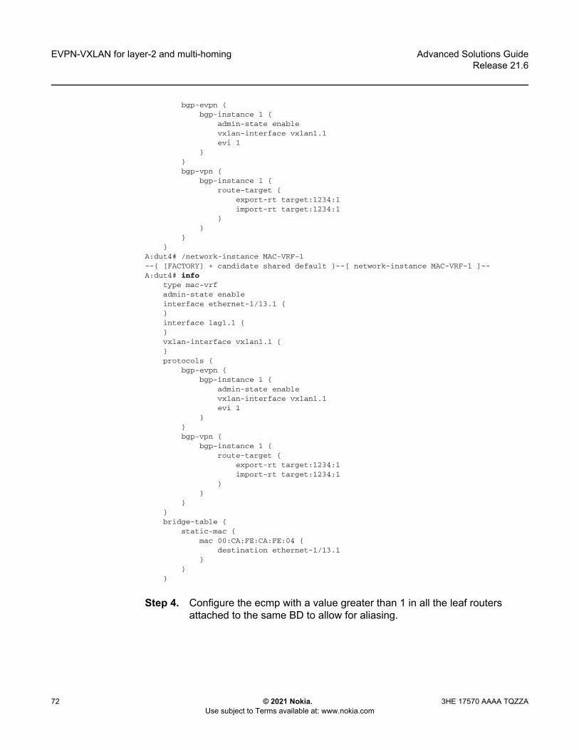
Step 3. Configure the association of the ES interface with the MAC-VRF. Example: ES interface association with the MAC-VRFIn this example, interface lag1.1 is added to the MAC-VRF. The association is based on the configuration under the ES and no further configuration is needed at the MAC-VRF level.

A:dut2# /network-instance MAC-VRF-1--{ [FACTORY] + candidate shared default }--[ network-instance MAC-VRF-1 ]--A:dut2# info

type mac-vrfadmin-state enableinterface ethernet-1/12.1 {}interface lag1.1 {}vxlan-interface vxlan1.1 {}protocols {

EVPN-VXLAN for layer-2 and multi-homing

72

Advanced Solutions GuideRelease 21.6

© 2021 Nokia. Use subject to Terms available at: www.nokia.com

3HE 17570 AAAA TQZZA

bgp-evpn {bgp-instance 1 {

admin-state enablevxlan-interface vxlan1.1evi 1

}}bgp-vpn {

bgp-instance 1 {route-target {

export-rt target:1234:1import-rt target:1234:1

}}

}}

A:dut4# /network-instance MAC-VRF-1--{ [FACTORY] + candidate shared default }--[ network-instance MAC-VRF-1 ]--A:dut4# info

type mac-vrfadmin-state enableinterface ethernet-1/13.1 {}interface lag1.1 {}vxlan-interface vxlan1.1 {}protocols {

bgp-evpn {bgp-instance 1 {

admin-state enablevxlan-interface vxlan1.1evi 1

}}bgp-vpn {

bgp-instance 1 {route-target {

export-rt target:1234:1import-rt target:1234:1

}}

}}bridge-table {

static-mac {mac 00:CA:FE:CA:FE:04 {

destination ethernet-1/13.1}

}}

Step 4. Configure the ecmp with a value greater than 1 in all the leaf routers attached to the same BD to allow for aliasing.

Advanced Solutions GuideRelease 21.6

EVPN-VXLAN for layer-2 and multi-homing

3HE 17570 AAAA TQZZA © 2021 Nokia. Use subject to Terms available at: www.nokia.com

73

Example: Configure ecmpIn the following, LEAF-3 is configured with ecmp 2.

--{ [FACTORY] + candidate shared default }--[ network-instance MAC-VRF-1 ]--A:dut3# info detail flat | grep ecmpset / network-instance MAC-VRF-1 protocols bgp-evpn bgp-instance 1 ecmp 2

Step 5. Review the configuration and commit the changes.A:dut2# commit stay--{ candidate shared default }--[ ]--

4.4.2.1 Using multi-homing as all-active MLAG for non-EVPN layer-2 BDs

An example of ESs in a non-EVPN layer-2 BD is shown in Figure 7. In this scenario, EVPN only runs locally between the leaf routers of the two pairs, but not globally in the network. The two leaf tiers (LEAF-4/5 and LEAF-2/3) are connected via layer-2 sub-interfaces, and not VXLAN. Each leaf is configured with two ESs. LEAF-4 is configured with ES-6 for multi-homing to server-6, and ES-45 for multi-homing to the LEAF-2/3 tier. The configuration of the ES previously described also apply to these topologies, with the exception that each ES would use a different name, ESI, and lag interface.

As noted in the multi-homing configuration procedure, configuring the ecmp with a value greater than 1 in all the leaf routers attached to the same BD is not required If the multi-homing ES is used locally as a layer-2 MLAG.

Note: This step is only required if Multi-Homing is used in an EVPN-VXLAN BD distributed among multiple Leaf routers. If the Multi-Homing ES is used locally as a Layer-2 MLAG (Multi-chassis Link Aggregation Group) technique, this step can be skipped.

EVPN-VXLAN for layer-2 and multi-homing

74

Advanced Solutions GuideRelease 21.6

© 2021 Nokia. Use subject to Terms available at: www.nokia.com

3HE 17570 AAAA TQZZA

Figure 7 Use of ES for layer-2 MLAG scenarios

4.4.3 Checking the multi-homing operation

After the multi-homed leaf routers and the remote leaf are configured, the ES operation must be checked.

Example: Check the ES status

Use the following to check the status of the ES on LEAF-2 and LEAF-4. The output from this command must show the same DF for the same mac-vrf on both leaf routers, and the same candidate list for the ES on both leaf routers. The detail form of this command also provides information about timers and the DF election.

// Leaf-4--{ [FACTORY] + candidate shared default }--[ ]--A:dut4# show system network-instance ethernet-segments ES-1

Advanced Solutions GuideRelease 21.6

EVPN-VXLAN for layer-2 and multi-homing

3HE 17570 AAAA TQZZA © 2021 Nokia. Use subject to Terms available at: www.nokia.com

75

-------------------------------------------------------------------------------ES-1 is up, all-active

ESI : 01:24:24:24:24:24:24:00:00:01Alg : defaultPeers: 2.2.2.2Interface: lag1Network-instances:

MAC-VRF-1Candidates : 2.2.2.2, 4.4.4.4 (DF)Interface : lag1.1

-------------------------------------------------------------------------------Summary1 Ethernet Segments Up0 Ethernet Segments Down

----------------------------------------------------------------------------------{ [FACTORY] + candidate shared default }--[ ]--A:dut4# show system network-instance ethernet-segments ES-1 detail=================================================================================Ethernet Segment=================================================================================Name : ES-14.4.4.4 (DF)Admin State : enable Oper State : upESI : 01:24:24:24:24:24:24:00:00:01Multi-homing : all-active Oper Multi-homing : all-activeInterface : lag1ES Activation Timer : NoneDF Election : default Oper DF Election : defaultLast Change : 2021-02-15T11:07:01.412Z=================================================================================MAC-VRF Actv Timer Rem DFES-1 0 Yes--------------------------------------------------------------------------------DF Candidates--------------------------------------------------------------------------------Network-instance ES PeersMAC-VRF-1 2.2.2.2MAC-VRF-1 4.4.4.4 (DF)================================================================================--{ [FACTORY] + candidate shared default }--[ ]—// Leaf-2

--{ [FACTORY] + candidate shared default }--[ ]--A:dut2# show system network-instance ethernet-segments ES-1--------------------------------------------------------------------------------ES-1 is up, all-active

ESI : 01:24:24:24:24:24:24:00:00:01Alg : defaultPeers: 4.4.4.4

show system network-instance ethernet-segments ES-1Network-instances:

MAC-VRF-1Candidates : 2.2.2.2, 4.4.4.4 (DF)Interface : lag1.1

--------------------------------------------------------------------------------Summary1 Ethernet Segments Up0 Ethernet Segments Down

--------------------------------------------------------------------------------

EVPN-VXLAN for layer-2 and multi-homing

76

Advanced Solutions GuideRelease 21.6

© 2021 Nokia. Use subject to Terms available at: www.nokia.com

3HE 17570 AAAA TQZZA

--{ [FACTORY] + candidate shared default }--[ ]--

Example: Check ES and EVI routes

The exchange of ES routes (used for DF election and ES discovery) and AD per ES/EVI routes (used to indicate the association of Leaf services to ES) can be checked with the following commands.

Note that LEAF-2 should have a type 4 route for the ES originating from LEAF-4. There should also be one AD per EVI and one AD per ES route from LEAF-4 for MAC-VRF-1. AD routes are advertised for each MAC-VRF that are part of the ES.

// Received ES routes or routes type 4 on Leaf-2--{ [FACTORY] + candidate shared default }--[ ]--A:dut2# show network-instance default protocols bgp routes evpn route-type 4 summary------------------------------------------------------------------------------------Show report for the BGP route table of network-instance "default"------------------------------------------------------------------------------------Status codes: u=used, *=valid, >=best, x=staleOrigin codes: i=IGP, e=EGP, ?=incomplete------------------------------------------------------------------------------------BGP Router ID: 2.2.2.2 AS: 2222 Local AS: 2222-----------------------------------------------------------------------------------Type 4 Ethernet Segment Routes+--------+---------------+-------------------+--------------+---------+-----------+| Status | Route- | ESI | originating | neighbor| Next-Hop || | distinguisher | | -router | | |+========+===============+===================+==============+=========+===========+| u*> | 4.4.4.4:0 | 01:24:24:24:24:24:| 4.4.4.4 | 4.4.4.4 | 4.4.4.4 || | | 24:00:00:01 | | | |+--------+---------------+-------------------+------------------------+-----------+-----------------------------------------------------------------------------------1 Ethernet Segment routes 1 used, 1 valid------------------------------------------------------------------------------------{ [FACTORY] + candidate shared default }--[ ]--A:dut2#/* Received AD routes or routes type 1 on Leaf-2. The AD per ES route uses Eth-Tag= MAX-ET (all FFs). */

--{ [FACTORY] + candidate shared default }--[ ]--A:dut2# show network-instance default protocols bgp routes evpn route-type 1 summaryShow report for the BGP route table of network-instance "default"-------------------------------------------------------------------------------------Status codes: u=used, *=valid, >=best, x=staleOrigin codes: i=IGP, e=EGP, ?=incomplete------------------------------------------------------------------------------------BGP Router ID: 2.2.2.2 AS: 2222 Local AS: 2222------------------------------------------------------------------------------------------------------------------------------------------------------------------------Type 1 Ethernet Auto-Discovery Routes+--------+---------------+------------------+------------+---------+---------+-----+| Status | Route- | ESI | Tag-ID | neighbor|Next-hop | VNI || | distinguisher | | | | | |

Advanced Solutions GuideRelease 21.6

EVPN-VXLAN for layer-2 and multi-homing

3HE 17570 AAAA TQZZA © 2021 Nokia. Use subject to Terms available at: www.nokia.com

77

+========+===============+==================+============+===================+=====+| u*> | 4.4.4.4:1 | 01:24:24:24:24: | 0 | 4.4.4.4 | 4.4.4.4 | - || | | 24:24:00:00:01 | | | | || u*> | 4.4.4.4:1 | 01:24:24:24:24: | 4294967295 | 4.4.4.4 | 4.4.4.4 | - || | | 24:24:00:00:01 | | | | |+--------+---------------+------------------+------------+---------+---------+-----+2 Ethernet Auto-Discovery routes 2 used, 2 valid--------------------------------------------------------------------------------------{ [FACTORY] + candidate shared default }--[ ]----{ [FACTORY] + candidate shared default }--[ ]--A:dut2# show network-instance default protocols bgp routes evpn route-type 1 detail-------------------------------------------------------------------------------------Show report for the EVPN routes to network "*" network-instance "default"------------------------------------------------------------------------------------Route Distinguisher: 4.4.4.4:1Tag-ID : 0ESI : 01:24:24:24:24:24:24:00:00:01neighbor : 4.4.4.4Received paths : 1

Path 1: <Best,Valid,Used,>ESI : 01:24:24:24:24:24:24:00:00:01Route source : neighbor 4.4.4.4 (last modified 4h38m27s ago)Route preference: No MED, LocalPref is 100Atomic Aggr : falseBGP next-hop : 4.4.4.4AS Path : iCommunities : [target:1234:1, bgp-tunnel-encap:VXLAN]RR Attributes : No Originator-ID, Cluster-List is []Aggregation : NoneUnknown Attr : NoneInvalid Reason : NoneTie Break Reason: none

------------------------------------------------------------------------------------Route Distinguisher: 4.4.4.4:1Tag-ID : 4294967295ESI : 01:24:24:24:24:24:24:00:00:01neighbor : 4.4.4.4Received paths : 1

Path 1: <Best,Valid,Used,>ESI : 01:24:24:24:24:24:24:00:00:01Route source : neighbor 4.4.4.4 (last modified 4h38m27s ago)Route preference: No MED, LocalPref is 100Atomic Aggr : falseBGP next-hop : 4.4.4.4AS Path : iCommunities : [target:1234:1, esi-label:0/All-Active]RR Attributes : No Originator-ID, Cluster-List is []Aggregation : NoneUnknown Attr : NoneInvalid Reason : NoneTie Break Reason: none

--------------------------------------------------------------------------------------{ [FACTORY] + candidate shared default }--[ ]--

Example: Check the MAC/IP route

EVPN-VXLAN for layer-2 and multi-homing

78

Advanced Solutions GuideRelease 21.6

© 2021 Nokia. Use subject to Terms available at: www.nokia.com

3HE 17570 AAAA TQZZA

MAC/IP routes advertised for MACs learned on the ES sub-interfaces are advertised with the ESI of ES-1. The RIB state for the MAC/IP routes can be used to check this. The following command checks the MAC/IP route for MAC 00:00:00:00:00:01 on LEAF-3:

--{ [FACTORY] + candidate shared default }--[ ]--A:dut3# show network-instance default protocols bgp routes evpn route-type 2 summary--------------------------------------------------------------------------------------------------------Show report for the BGP route table of network-instance "default"--------------------------------------------------------------------------------------------------------Status codes: u=used, *=valid, >=best, x=staleOrigin codes: i=IGP, e=EGP, ?=incomplete--------------------------------------------------------------------------------------------------------BGP Router ID: 3.3.3.3 AS: 3333 Local AS: 3-------------------------------------------------------------------------------------------------------Type 2 MAC-IP Advertisement Routes+--------+------------+-----+--------------+---------+---------+---------+---+-----------------+-------+| Status | Route-dis- | Tag | MAC-address | IP- | neighbor| Next-Hop|VNI| ESI | MAC || | tinguisher | -ID | | address | | | | | Mob. |+========+============+=====+==============+=========+=========+=========+===+=================+=======+| u*> | 2.2.2.2:1 | 0 | 00:00:00:00: | 0.0.0.0 | 2.2.2.2 | 2.2.2.2 | 1 | 00:00:00:00:00: | - || | | | 00:02 | | | | | 00:00:00:00:0 0| || u*> | 4.4.4.4:1 | 0 | 00:00:00:00: | 0.0.0.0 | 4.4.4.4 | 4.4.4.4 | 1 | 01:24:24:24:24: | - || | | | 00:01 | | | | | 24:24:00:00:01 | || u*> | 4.4.4.4:1 | 0 | 00:00:00:00: | 0.0.0.0 | 4.4.4.4 | 4.4.4.4 | 1 | 00:00:00:00:00: | - || | | | 00:0 4 | | | | | 00:00:00:00:00 | || u*> | 4.4.4.4:1 | 0 | 00:CA:FE:CA: | 0.0.0.0 | 4.4.4.4 | 4.4.4.4 | 1 | 00:00:00:00:00: |Seq:0/ || | | | FE:04 | | | | | 00:00:00:00:00 |Static |+--------+------------+-----+--------------+---------+---------+---------+---+-----------------+-------+--------------------------------------------------------------------------------------------------------4 MAC-IP Advertisement routes 4 used, 4 valid----------------------------------------------------------------------------------------------------------{ [FACTORY] + candidate shared default }--[ ]--

Example: Check the ES destination

Once AD routes are received from LEAF-2 and LEAF-4, and the MAC/IP route is tagged with the ESI, LEAF-3 creates an ES destination resolved to as many VTEPs as leafs advertising the AD routes (up to a maximum of the ecmp setting on LEAF-3). Use the following to check the ES destination for ES-1 created on LEAF-3.

--{ [FACTORY] + candidate shared default }--[ ]--A:dut3# show tunnel-interface vxlan1 vxlan-interface 1 bridge-table unicast-destinations destination *------------------------------------------------------------------------------------------------------Show report for vxlan-interface vxlan1.1 unicast destinations------------------------------------------------------------------------------------------------------Destinations------------------------------------------------------------------------------+--------------+------------+-------------------+-----------------------------+| VTEP Address | Egress VNI | Destination-index | Number MACs (Active/Failed) |+==============+============+===================+=============================+| 2.2.2.2 | 1 | 278779228840 | 1(1/0) || 4.4.4.4 | 1 | 278779228838 | 2(2/0) |+--------------+------------+-------------------+-----------------------------+-------------------------------------------------------------------------------

Advanced Solutions GuideRelease 21.6

EVPN-VXLAN for layer-2 and multi-homing

3HE 17570 AAAA TQZZA © 2021 Nokia. Use subject to Terms available at: www.nokia.com

79

Ethernet Segment Destinations------------------------------------------------------------------------------------------------------+-------------------------------+-------------------+------------------+-----------------------------+| ESI | Destination-index | VTEPs | Number MACs (Active/Failed) |+===============================+===================+==================+=============================+| 01:24:24:24:24:24:24:00:00:01 | | 2.2.2.2, 4.4.4.4 | 0(0/0) |+-------------------------------+-------------------+------------------+-----------------------------+------------------------------------------------------------------------------------------------------Summary

3 unicast-destinations, 2 non-es, 1 es3 MAC addresses, 3 active, 0 non-active

-------------------------------------------------------------------------------------------------------{ [FACTORY] + candidate shared default }--[ ]--

Example: Check MAC programming

The following command shows how LEAF-3 programs the MACs received for the ES as associated to an ES destination

--{ [FACTORY] + candidate shared default }--[ ]--A:dut3# show network-instance MAC-VRF-1 bridge-table mac-table mac 00:00:00:00:00:01------------------------------------------------------------------------------------Mac-table of network instance MAC-VRF-1-----------------------------------------------------------------------------------Mac : 00:00:00:00:00:01Destination : vxlan-interface:vxlan1.1 esi:01:24:24:24:24:24:24:00:00:01Dest Index : 278779228850Type : evpnProgramming Status : SuccessAging : N/ALast Update : 2021-02-16T15:51:09.000ZDuplicate Detect time : N/AHold down time remaining: N/A-------------------------------------------------------------------------------------{ [FACTORY] + candidate shared default }--[ ]--

Example: Check sub-interface ES association LEAF-2)

On the non-DF (in this example, LEAF-2), the MAC-VRF interface included in ES-1 (lag1.1) shows the "multicast-forwarding" flag as none. This means that the interface will not forward BUM traffic to the CE/server when it is received on VXLAN. The following shows how the state for the sub-interface itself will show the association with ES-1 and the DF state:

--{ [FACTORY] + candidate shared default }--[ ]--A:dut2# info from state network-instance MAC-VRF-1 interface lag1.1

network-instance MAC-VRF-1 {interface lag1.1 {

oper-state upoper-mac-learning upindex 12multicast-forwarding none

}}

--{ [FACTORY] + candidate shared default }--[ ]--

EVPN-VXLAN for layer-2 and multi-homing

80

Advanced Solutions GuideRelease 21.6

© 2021 Nokia. Use subject to Terms available at: www.nokia.com

3HE 17570 AAAA TQZZA

--{ [FACTORY] + candidate shared default }--[ ]--A:dut2# info from state interface lag1 subinterface 1 ethernet-segment-association

interface lag1 {subinterface 1 {

ethernet-segment-association {ethernet-segment ES-1es-managed truedesignated-forwarder false

}}

Example: Check sub-interface ES association LEAF-4)

On the DF (in this example, LEAF-4), the MAC-VRF interface in ES-1 (lag1.1) shows the "multicast-forwarding" flag as BUM. The following shows how the state for the sub-interface itself will show the association with ES-1 and the DF state.

--{ [FACTORY] + candidate shared default }--[ ]--A:dut4# info from state network-instance MAC-VRF-1 interface lag1.1

network-instance MAC-VRF-1 {interface lag1.1 {

oper-state upoper-mac-learning upindex 11multicast-forwarding BUM

}}

--{ [FACTORY] + candidate shared default }--[ ]----{ [FACTORY] + candidate shared default }--[ ]--A:dut4# info from state interface lag1 subinterface 1 ethernet-segment-association

interface lag1 {subinterface 1 {

ethernet-segment-association {ethernet-segment ES-1es-managed truedesignated-forwarder true

}}

}

Example: EVPN related logs

The evpn_mgr application has logs that are triggered when the DF state changes on an ES as shown in the following:

[root@dut2 srlinux]#2021-02-15T02:59:41.888505-08:00 dut2 local6|NOTI sr_evpn_mgr: evpn|1905|1905|00086|N:BGP-EVPN attachment circuit on ethernet segment ES-1 on network instance MAC-VRF-1and bgp instance 1 is now a non-designated forwarder.

2021-02-15T02:59:44.859295-08:00 dut2 local6|NOTI sr_evpn_mgr: evpn|1905|1905|00087|N:BGP-EVPN attachment circuit on ethernet segment ES-1 on network instance MAC-VRF-1and bgp instance 1 is now a designated forwarder.

Advanced Solutions GuideRelease 21.6

EVPN-VXLAN for layer 3

3HE 17570 AAAA TQZZA © 2021 Nokia. Use subject to Terms available at: www.nokia.com

81

5 EVPN-VXLAN for layer 3The EVPN Layer 3 configuration model builds on the model for EVPN routes described in Chapter 4, EVPN-VXLAN for layer-2 and multi-homing. Understanding the concepts in the EVPN-VXLAN Layer-2 chapter is required to understand this chapter.

This chapter addresses connectivity between subnets across multiple Broadcast Domains (BDs) of the same tenant as defined in the EVPN Interface-less (IFL) model [draft-ietf-bess-evpn-prefix-advertisement]. It is based on the advertisement and processing of IP prefixes using EVPN type 5 routes. This chapter defines how CEs or servers can be multi-homed to multiple leaf nodes in an EVPN IFL network. It also describes other EVPN L3 topics such as:

• IRB subinterface extensions for EVPN-VXLAN Layer 3• unicast routing PE-CE • layer 3 host mobility

5.1 Applicability

The information and configuration in this chapter are based on SR Linux Release 21.6.

5.2 Overview

Figure 8 shows four leaf routers attached to the same tenant or IP-VRF domain. Servers are connected to different subnets and, therefore, different BDs. The leaf routers provide inter-subnet forwarding by using the EVPN IFL model as defined in [draft-ietf-bess-evpn-prefix-advertisement]. The SR Linux implementation is fully standard and third-party routers, such as LEAF-4, can be connected to the same IP-VRF domain as SR Linux routers.

EVPN-VXLAN for layer 3

82

Advanced Solutions GuideRelease 21.6

© 2021 Nokia. Use subject to Terms available at: www.nokia.com

3HE 17570 AAAA TQZZA

Figure 8 EVPN IP-VRF domain in a multi-tenant DC

The procedures in this chapter define the configuration and operation for:

• the EVPN IFL model for EVPN-VXLAN Layer 3 and the EVPN IP prefix routes• multi-homing in an EVPN-VXLAN Layer 3 solution• host route mobility aspects• PE-CE unicast routing on EVPN-VXLAN Layer 3 networks• EVPN-VXLAN Layer 3 feature parity for IPv6 prefixes

5.3 Configuring EVPN-VXLAN IP-VRF domains

Figure 9 shows the configuration of an EVPN-VXLAN IP-VRF-10 distributed in three leaf routers, with different subnets, and multi-homing for SERVER-1.

sw1101

ARPARP

SERVER-110.0.0.1MAC M1

SRL LEAF-1 SRL LEAF-2 SRL LEAF-3

Third-partyLEAF-4

SERVER-210.0.0.2MAC M2

ROUTER10.0.0.3MAC M3Subnets

192.0.1.0/24192.0.2.0/24

SERVER-430.0.0.4MAC M4

SERVER-540.0.0.5MAC M5

ES-1

MAC-VRF 1RD1/RT1

VNI1

IP-Prefix10.0.0.0/2410.0.0.2/32

VNI10Next-Hop leaf-1

MAC/IPM2/10.0.0.1/ESI-1

VNI1Next-Hop leaf-1

IP-Prefix10.0.0.0/24

VNI10Next-Hop leaf-2

IP-Prefix30.0.0.0/24

VNI10Next-Hop leaf-3

IP-Prefix40.0.0.0/2440.0.0.5/32

VNI10Next-Hop leaf-4

IP-VRFRD1/RT10

VNI10

IP-VRFRD1/RT10

VNI10

IP-VRFRD1/RT10

VNI10 IP-VRFRD1/RT10

VNI10MAC-VRF 2RD2/RT2

VNI2

MAC-VRF 3RD3/RT3

VNI3 MAC-VRF 4RD4/RT4

VNI4BGP or Static

(BFD)

Advanced Solutions GuideRelease 21.6

EVPN-VXLAN for layer 3

3HE 17570 AAAA TQZZA © 2021 Nokia. Use subject to Terms available at: www.nokia.com

83

Figure 9 Example of EVPN-VXLAN IP-VRF domain

5.3.1 Preconfiguring the underlay network

Prior to configuring the overlay BD, the underlay connectivity must be configured.

This chapter uses the same underlay configuration defined for EVPN-VXLAN Layer-2 and Multi-Homing. Refer to section 4.3.1 Configuring the underlay network in chapter 4 and review this section to understand the underlay configuration before proceeding.

5.3.2 Configuring the LEAF-3 IP-VRF domain

Once LEAF-3 is pre-configured as defined in Preconfiguring the underlay network, use the following steps to enable EVPN-VXLAN on LEAF-3.

sw1102

HOST-3IP-103..1.1.1/24

MAC-00:00:00:00:00:03

SRL LEAF-2

PE-CEBGP IPv4

EVPN-VXLAN

SRL LEAF-4 SRL LEAF-3

SERVER-1

ES-1

irb0.24Anycast-IP .254

MAC-00.00.5E:00:01:01

LAG-1e1/12.24

e1/2.3e1/13.4lag1.24lag1.24

e1/22.2

20.1.1.2/24IP-VRF-10RD1/RT10

VNI10

IP-VRF-10RD1/RT10

VNI10

IP-VRF-10RD1/RT10

VNI10

BD3RD31/RT3

VNI3

BD24RD41/RT24

VNI24

BD4RD42/RT4

VNI4

BD2RD41/RT2

VNI2

BD24RD22/RT24

VNI24

CE-3IP-20.1.1.3/24

MAC-00:01:03:FF:00:0B

HOST-4IP-104.1.1.1/24

MAC-00:00:00:00:00:04HOST-2

IP-101.1.1.2/24MAC-00:00:00:00:00:02

HOST-12IP-101.1.1.1/24

MAC-00:00:64:01:01:01

EVPN-VXLAN for layer 3

84

Advanced Solutions GuideRelease 21.6

© 2021 Nokia. Use subject to Terms available at: www.nokia.com

3HE 17570 AAAA TQZZA

As shown in Figure 9, LEAF-3 is attached to IP-VRF-10 and HOST-3 is connected to BD3. BD3 is mapped to subnet 103.1.1.0/24 and its IRB sub-interface is the default-gateway to all hosts in BD3.

Step 1. In candidate mode, create the interfaces and bridged sub-interfaces that will connect LEAF-3 BD3 to HOST-3. In this example:- Ethernet-1/2 connects HOST-3 to LEAF-3. Although this interface

could be defined untagged, this example configures the interface as tagged (vlan-tagging true).

- A sub-interface with index 3 is created under the interface and must be configured as type bridged. Bridged sub-interfaces can be associated to MAC-VRF instances as described in Chapter 4.

- The sub-interface uses vlan-id any, which captures any traffic that is not specified in other sub-interfaces of the same interface.

--{ [FACTORY] + candidate shared default }--[ interface ethernet-1/2 ]--# info

admin-state enablevlan-tagging truesubinterface 3 {

type bridgedadmin-state enablevlan {

encap {single-tagged {

vlan-id any}

}}

}

Step 2. After creating the access sub-interfaces, create the vxlan-interfaces. This allows MAC-VRFs of the same BD to be connected throughout the IP fabric.In this example, no other leaf router is attached to BD3, so no vxlan-interface is needed in BD3. The configuration of the vxlan-interface is only shown for completeness. Reference Chapter 4 for details on vxlan-interfaces and their characteristics.Example: vxlan1 vxlan-interface 3 configuration

--{ [FACTORY] + candidate shared default }--[ tunnel-interface vxlan1 ]--# info

vxlan-interface 3 {

Note: The IRB sub-interface will expect no vlan tags so that traffic forwarded from HOST-3 can be routed. If HOST-3 sends frames tagged with a vlan-id, the frames would be classified in the BD3 context, but the sub-interface will not strip off the vlan tag, and frames will not be routed.

Advanced Solutions GuideRelease 21.6

EVPN-VXLAN for layer 3

3HE 17570 AAAA TQZZA © 2021 Nokia. Use subject to Terms available at: www.nokia.com

85

type bridgedingress {

vni 3}

}

Step 3. IP-VRF instances in the leaf routers are also connected by VXLAN tunnels, therefore, vxlan-interfaces of type routed must be created. In this example, tunnel-interface vxlan2 vxlan-interface 10 is configured. While the configuration of the routed vxlan-interface is similar to the bridged vxlan-interface, this type ensures a routed vxlan-interface only attaches to an ip-vrf, and a bridged vxlan-interface only attaches to a mac-vrf.Example: VXLAN tunnel configuration

--{ [FACTORY] + candidate shared default }--[ tunnel-interface vxlan2 ]--# info

vxlan-interface 10 {type routedingress {

vni 10}

}

Step 4. Configure the IRB interface and sub-interface that links BD3 and IP-VRF-10 together to allow packets from/to subnet 103.1.1.0/24 to route to/from remote subnets in the local or remote leaf routers of the same tenant.Note that since BD3 is not present in another leaf, the IRB sub-interface is not configured as an anycast-gw sub-interface. However, an operator may want to configure all IRB sub-interfaces as anycast-gw in case the BD is extended later. Reference section 5.3.3, Configuring the IP-VRF Domain on LEAF-2 and LEAF-4 for anycast-gw configuration details.Example: IRB configuration

--{ [FACTORY] + candidate shared default }--[ interface irb0 ]--# info

subinterface 3 {ipv4 {

address 103.1.1.254/24 {}

}}

Step 5. Configure the network-instance type mac-vrf and associate it with the bridged IRB interfaces and the vxlan-interface. In the example that follows, BD3 is connected to HOST-3 and to the IRB sub-interface that is also attached to IP-VRF-10.Although the B is not needed, in this example, the bgp-evpn and vxlan configuration is shown for completeness. For details about bgp-vpn, bgp-evpn, and vxlan-interface configuration, refer to chapter 4.

EVPN-VXLAN for layer 3

86

Advanced Solutions GuideRelease 21.6

© 2021 Nokia. Use subject to Terms available at: www.nokia.com

3HE 17570 AAAA TQZZA

Example: mac-vrf configuration and bridged interface association--{ [FACTORY] + candidate shared default }--[ network-instance BD3 ]--# info

type mac-vrfinterface ethernet-1/2.3 {}interface irb0.3 {}vxlan-interface vxlan1.3 {}protocols {

bgp-evpn {bgp-instance 1 {

admin-state enablevxlan-interface vxlan1.3evi 3ecmp 2

}}bgp-vpn {

bgp-instance 1 {route-target {

export-rt target:64500:3import-rt target:64500:3

}}

}}

Step 6. Configure IP-VRF-10 with bgp-evpn enabled using the EVPN IFL model. In this example, IP-VRF is configured with the irb0.3 interface for connectivity to BD3 and vxlan2.10. This allows the extension of IP-VRF-10 to remote leaf routers. A loopback interface is configured in the IP-VRF to test connectivity among IP-VRFs of the same tenant.Once configured, all local routes learned on IP-VRF-10 route-table will be advertised in IP Prefix routes (or IPv6 Prefix routes for local IPv6 routes).Example: Enable EVPN IFL model on IP-VRF-10

--{ [FACTORY] + candidate shared default }--[ network-instance IP-VRF* ]--# info

network-instance IP-VRF-10 {type ip-vrfinterface irb0.3 {}interface lo10.2 {}vxlan-interface vxlan2.10 {}protocols {

bgp-evpn {bgp-instance 1 {

vxlan-interface vxlan2.10evi 10ecmp 2

}

Advanced Solutions GuideRelease 21.6

EVPN-VXLAN for layer 3

3HE 17570 AAAA TQZZA © 2021 Nokia. Use subject to Terms available at: www.nokia.com

87

}bgp-vpn {

bgp-instance 1 {route-target {

export-rt target:64500:10import-rt target:64500:10

}}

}}

}

The bgp-vpn instance is configured as described in Chapter 4 (with a network-instance of type ip-vrf). Likewise, the bgp-evpn container enables EVPN in the ip-vrf and associates it to the routed vxlan-interface. The RD and RT can be auto-derived from the evi just like they can in mac-vrfs. Explicitly configured RD/RTs can override the auto-configured ones. Import and export policies are supported.

Step 7. Review the changes. If correct, commit the changes.# commit stay--{ candidate shared default }--[ ]--

5.3.3 Configuring the IP-VRF Domain on LEAF-2 and LEAF-4

LEAF-2 and LEAF-4 are configured in the same way as LEAF-3, but with the addition of multi-homing, anycast-gw interfaces, and related configurations.

Use the following procedure to enable EVPN-VXLAN Layer 3 on LEAF-2 and LEAF-4. Considerations for configuring the IRB sub-interfaces (Step 4) are provided in section 5.3.3.1 IRB sub-interface considerations, if needed.

Step 1. In candidate mode, create the interfaces, and bridged sub-interfaces (including LAG) to connect HOST-2, HOST-4, SERVER-1, and CE-3.In this example, Ethernet Segment ES-1 is associated to lag1 and is multi-homed to SERVER-1 lag. LACP is enabled on lag1 (but can be disabled) and the admin-key, system-id-mac, and system-priority match on both LEAF-2 and LEAF-4.Example (1 of 2): Interfaces and bridged sub-interfaces configuration (LEAF-2)

// interfaces in Leaf-2--{ [FACTORY] + candidate shared default }--[ interface * ]--# info

interface ethernet-1/11 {description ES-1ethernet {

EVPN-VXLAN for layer 3

88

Advanced Solutions GuideRelease 21.6

© 2021 Nokia. Use subject to Terms available at: www.nokia.com

3HE 17570 AAAA TQZZA

aggregate-id lag1}

}interface ethernet-1/12 {

description to-host-2admin-state enablevlan-tagging truesubinterface 24 {

type bridgedvlan {

encap {single-tagged {

vlan-id any}

}}

}}interface ethernet-1/22 {

description to-CE-3vlan-tagging truesubinterface 2 {

type bridgedadmin-state enablevlan {

encap {single-tagged {

vlan-id 2}

}}

}}interface lag1 {

admin-state enablevlan-tagging truesubinterface 24 {

type bridgedvlan {

encap {single-tagged {

vlan-id 24}

}}

}lag {

lag-type lacpmember-speed 100Glacp {

interval FASTlacp-mode ACTIVEadmin-key 24system-id-mac 00:00:00:00:00:24system-priority 24

}}

}

Advanced Solutions GuideRelease 21.6

EVPN-VXLAN for layer 3

3HE 17570 AAAA TQZZA © 2021 Nokia. Use subject to Terms available at: www.nokia.com

89

Example (2 of 2): Interfaces and bridged sub-interfaces configuration (LEAF-4)

// Interfaces in Leaf-4--{ [FACTORY] + candidate shared default }--[ interface * ]--# info

interface ethernet-1/4 {description ES-1ethernet {

aggregate-id lag1}

}interface ethernet-1/13 {

description to-host-4admin-state enablevlan-tagging truesubinterface 4 {

type bridgedadmin-state enablevlan {

encap {single-tagged {

vlan-id any}

}}

}}interface lag1 {

admin-state enablevlan-tagging truesubinterface 24 {

type bridgedvlan {

encap {single-tagged {

vlan-id 24}

}}

}lag {

lag-type lacpmember-speed 100Glacp {

interval FASTlacp-mode ACTIVEadmin-key 24system-id-mac 00:00:00:00:00:24system-priority 24

}}

}

EVPN-VXLAN for layer 3

90

Advanced Solutions GuideRelease 21.6

© 2021 Nokia. Use subject to Terms available at: www.nokia.com

3HE 17570 AAAA TQZZA

Step 2. Create the all-active Ethernet Segment ES-1 that is attached to LEAF-2 and LEAF-4. Details about the ES configuration and operation can be found in Chapter 4. Note that the following example only shows the Ethernet Segment configuration. The bgp-vpn>bgp-instance 1 must also be configured as described in Chapter 4.Example: ES configuration

// ES-1 on Leaf-2--{ [FACTORY] + candidate shared default }--[ system network-instance protocolsevpn ethernet-segments ]--

# infobgp-instance 1 {

ethernet-segment ES-1 {admin-state enableesi 01:24:24:24:24:24:24:00:00:01interface lag1multi-homing-mode all-active

}}

// ES-1 on Leaf-4--{ [FACTORY] + candidate shared default }--[ system network-instance protocolsevpn ethernet-segments ]--

A:dut4# infobgp-instance 1 {

ethernet-segment ES-1 {admin-state enableesi 01:24:24:24:24:24:24:00:00:01interface lag1multi-homing-mode all-active

}

}

Step 3. Once the access bridged sub-interfaces are created, create the vxlan-interfaces to facilitate connectivity between network-instances across the IP fabric. The mac-vrf network-instances require both vxlan-interfaces of type bridged and ip-vrfs of type routed.In the following example, all the vxlan-interfaces for all network-instances on LEAF-2 and LEAF-4 nodes are configured as follows:Example: vxlan-interface configuration

// vxlan-interfaces on Leaf-2--{ [FACTORY] + candidate shared default }--[ tunnel-interface * ]--# info

tunnel-interface vxlan1 {vxlan-interface 2 {

type bridgedingress {

vni 2}

}vxlan-interface 24 {

type bridgedingress {

vni 24

Advanced Solutions GuideRelease 21.6

EVPN-VXLAN for layer 3

3HE 17570 AAAA TQZZA © 2021 Nokia. Use subject to Terms available at: www.nokia.com

91

}}

}tunnel-interface vxlan2 {

vxlan-interface 10 {type routedingress {

vni 10}

}}

// vxlan-interfaces on Leaf-4--{ [FACTORY] + candidate shared default }--[ tunnel-interface * ]--# info

tunnel-interface vxlan1 {vxlan-interface 4 {

type bridgedingress {

vni 4}

}vxlan-interface 24 {

type bridgedingress {

vni 24}

}}tunnel-interface vxlan2 {

vxlan-interface 10 {type routedingress {

vni 10}

}

}

Step 4. Configure the IRB sub-interfaces that will link the mac-vrf and ip-vrf network-instances for inter-subnet-forwarding. Refer to section 5.3.3.1 IRB sub-interface considerations, for details on configuring IRB sub-interfaces.Example: IRB sub-interface configuration

// IRB interfaces in Leaf-2--{ [FACTORY] + candidate shared default }--[ interface irb* ]--# info

interface irb0 {subinterface 2 {

ipv4 {address 20.1.1.2/24 {}arp {

learn-unsolicited true]

}}anycast-gw {}

EVPN-VXLAN for layer 3

92

Advanced Solutions GuideRelease 21.6

© 2021 Nokia. Use subject to Terms available at: www.nokia.com

3HE 17570 AAAA TQZZA

}subinterface 24 {

ipv4 {address 101.1.1.2/24 {}address 101.1.1.254/24 {

anycast-gw trueprimary

}address 102.1.1.254/24 {}arp {

learn-unsolicited truedebug [

messages]host-route {

populate dynamic {}

}evpn {

advertise dynamic {}

}}

}anycast-gw {}

}}

// IRB interfaces in Leaf-4--{ [FACTORY] + candidate shared default }--[ interface irb* ]--# info

interface irb0 {subinterface 4 {

ipv4 {address 104.1.1.4/24 {}address 104.1.1.254/24 {

anycast-gw trueprimary

}arp {

learn-unsolicited truedebug [

messages]

}}anycast-gw {}

}subinterface 24 {

ipv4 {address 101.1.1.4/24 {}address 101.1.1.254/24 {

anycast-gw trueprimary

Advanced Solutions GuideRelease 21.6

EVPN-VXLAN for layer 3

3HE 17570 AAAA TQZZA © 2021 Nokia. Use subject to Terms available at: www.nokia.com

93

}arp {

learn-unsolicited truedebug [

messages]host-route {

populate dynamic {}

}evpn {

advertise dynamic {}

}}

}anycast-gw {}

}

Step 5. Configure the network-instances of type mac-vrf and associate the bridged sub-interfaces, irb sub-interfaces, and vxlan-interfaces. Then enable bgp-evpn.Example: network instance configuration and association

// MAC-VRFs in Leaf-2--{ [FACTORY] + candidate shared default }--[ network-instance BD* ]--# info

network-instance BD2 {type mac-vrfinterface ethernet-1/22.2 {}interface irb0.2 {}vxlan-interface vxlan1.2 {}protocols {

bgp-evpn {bgp-instance 1 {

admin-state enablevxlan-interface vxlan1.2evi 2ecmp 2

}}bgp-vpn {

bgp-instance 1 {route-target {

export-rt target:64500:2import-rt target:64500:2

}}

}}

}network-instance BD24 {

type mac-vrfinterface ethernet-1/12.24 {

EVPN-VXLAN for layer 3

94

Advanced Solutions GuideRelease 21.6

© 2021 Nokia. Use subject to Terms available at: www.nokia.com

3HE 17570 AAAA TQZZA

}interface irb0.24 {}interface lag1.24 {}vxlan-interface vxlan1.24 {}protocols {

bgp-evpn {bgp-instance 1 {

admin-state enablevxlan-interface vxlan1.24evi 24ecmp 2

}}bgp-vpn {

bgp-instance 1 {route-target {

export-rt target:64500:24import-rt target:64500:24

}}

}}

}// MAC-VRFs in Leaf-4--{ [FACTORY] + candidate shared default }--[ network-instance BD* ]--# info

network-instance BD24 {type mac-vrfinterface irb0.24 {}interface lag1.24 {}vxlan-interface vxlan1.24 {}protocols {

bgp-evpn {bgp-instance 1 {

admin-state enablevxlan-interface vxlan1.24evi 24ecmp 2

}}bgp-vpn {

bgp-instance 1 {route-target {

export-rt target:64500:24import-rt target:64500:24

}}

}}

}network-instance BD4 {

type mac-vrfinterface ethernet-1/13.4 {

Advanced Solutions GuideRelease 21.6

EVPN-VXLAN for layer 3

3HE 17570 AAAA TQZZA © 2021 Nokia. Use subject to Terms available at: www.nokia.com

95

}interface irb0.4 {}vxlan-interface vxlan1.4 {}protocols {

bgp-evpn {bgp-instance 1 {

admin-state enablevxlan-interface vxlan1.4evi 4ecmp 2

}}bgp-vpn {

bgp-instance 1 {route-target {

export-rt target:64500:4import-rt target:64500:4

}}

}}

}

Step 6. Configure IP-VRF-10 with bgp-evpn enabled with the EVPN IFL model. The IP-VRF is configured with the IRB sub-interfaces previously created for BD2, BD4, and BD24. The IP-VRF instances are connected VXLAN tunnels, so routed vxlan-interfaces need to be associated to IP-VRF-10. A loopback interface is configured in the IP-VRF to test connectivity among IP-VRFs of the same tenant.In the following example, LEAF-2's IP-VRF is configured with a BGP PE-CE neighbor to CE-3.Example: IP-VRF-10 configuration

// IP-VRF-10 in Leaf-2--{ [FACTORY] + candidate shared default }--[ network-instance IP-VRF* ]--# info

network-instance IP-VRF-10 {type ip-vrfinterface irb0.2 {}interface irb0.24 {}interface lo10.2 {}vxlan-interface vxlan2.10 {}protocols {

bgp-evpn {bgp-instance 1 {

vxlan-interface vxlan2.10evi 10ecmp 2

}

EVPN-VXLAN for layer 3

96

Advanced Solutions GuideRelease 21.6

© 2021 Nokia. Use subject to Terms available at: www.nokia.com

3HE 17570 AAAA TQZZA

}bgp {

admin-state enableautonomous-system 645002router-id 2.2.2.2group eBGP-PE-CE {

admin-state enableexport-policy export-allimport-policy import-allipv4-unicast {

admin-state enable}

}neighbor 20.1.1.3 {

peer-as 645003peer-group eBGP-PE-CElocal-as 645002 {}transport {

local-address 20.1.1.2}

}}bgp-vpn {

bgp-instance 1 {route-target {

export-rt target:64500:10import-rt target:64500:10

}}

}}

}// IP-VRF-10 in Leaf-4--{ [FACTORY] + candidate shared default }--[ network-instance IP-VRF* ]--# info

network-instance IP-VRF-10 {type ip-vrfinterface irb0.4 {}interface irb0.24 {}interface lo10.2 {}vxlan-interface vxlan2.10 {}protocols {

bgp-evpn {bgp-instance 1 {

vxlan-interface vxlan2.10evi 10ecmp 2

}}bgp-vpn {

bgp-instance 1 {route-target {

export-rt target:64500:10import-rt target:64500:10

Advanced Solutions GuideRelease 21.6

EVPN-VXLAN for layer 3

3HE 17570 AAAA TQZZA © 2021 Nokia. Use subject to Terms available at: www.nokia.com

97

}}

}}

}

Step 7. Review the changes. If correct, commit the changes.A:dut2# commit stay--{ candidate shared default }--[ ]--

5.3.3.1 IRB sub-interface considerations

The following are considerations for configuring IRB sub-interfaces (performed in Step 4).

IRB sub-interfaces on BDs that are distributed to multiple leaf nodes must be configured with at least one anycast-gw IP address and an anycast-gw MAC address. When the anycast-gw container is configured, the anycast-gw MAC address is auto-derived as 00:00:5E:00:01:01 in all the leaf nodes. The MAC address can also be explicitly configured if desired. In addition:

• The same anycast-gw IP and MAC address must be configured on all IRBs of the same BD.

• All the hosts attached to the same BD use the same default-gateway (that is, the anycast-gw IP) irrespective of the leaf they are connected to. For example, irb0 sub-interfaces 24 are configured with the same anycast-gw IP on LEAF-2 and LEAF-4 (101.1.1.254) in the configuration example.

• Default gateway redundancy in DCs is realized using anycast-gws, and not VRRP. Anycast-gws avoid upstream tromboning for hosts that are multi-homed to multiple leaf nodes or for single-homed hosts that move to other leaf nodes of the same BD.

IRB sub-interfaces on BDs that are distributed may also be configured with non-anycast-gw IP addresses. This is only done when separate IPs are needed to check connectivity per leaf. For example, when LEAF-2 is configured with non-anycast-gw IPs 101.1.1.2 and 102.1.1.254, and LEAF-4 is configured with 104.1.1.4. and anycast-gw IPs exist in multiple nodes, the anycast-gw IPs should not be used in ICMP tools to check the availability of a leaf. Non-anycast-gw IPs should be used instead.

IRB sub-interfaces on distributed BDs should be configured with the following commands, as shown for subinterface 24 in LEAF-2 and LEAF-4 in the configuration example:

EVPN-VXLAN for layer 3

98

Advanced Solutions GuideRelease 21.6

© 2021 Nokia. Use subject to Terms available at: www.nokia.com

3HE 17570 AAAA TQZZA

• arp learn-unsolicited true - Triggers the learning of ARP entries out of any ARP packet arriving at the IRB sub-interface, regardless of whether there was an ARP-Request issued from the IRB.

• arp host-route populate dynamic - Creates host routes (arp-nd) in the IP-VRF route-table from learned dynamic ARP entries in the IRB. The arp-nd host routes are then advertised to the remote leaf nodes. This assists the routing of downstream traffic to a given host without hair-pinning traffic via another leaf connected to the same BD of the host, but not connected to the host directly.

• arp evpn advertise dynamic - Advertises EVPN MAC/IP routes that include the MAC and the IP of the dynamic ARP entries. The advertisement of these routes synchronizes the ARP caches in all the IRB sub-interfaces of the same BD.

IRB sub-interfaces on BDs that are not distributed (that is, BDs attached to only one Leaf node) do not need to be configured with the following:

• arp host-route-populate dynamic as downstream routing is always direct to the connected leaf

• arp evpn advertise dynamic as ARP entries do not need to be synchronized with any other node

Examples of non-distributed BDs are BD2, BD4, and BD3 as shown in Figure 9. Their corresponding IRB sub-interfaces do not create host-routes or advertise EVPN MAC/IP routes for the ARP entries.

5.3.4 Configuring EVPN IFL interoperability to EVPN IFF unnumbered model

While EVPN IFL for VXLAN is supported by most DC vendors, Nuage WBX or VSC/VRS use the EVPN IFF Unnumbered model. By default, the SR Linux EVPN IFL (interface-less) model does not inter-operate with the EVPN IFF (interface-full) model. However, it is possible to configure the SR Linux EVPN IFL model to inter-operate with the EVPN IFF model.

For more information about EVPN IFL vs EVPN IFF models, see the SR Linux EVPN-VXLAN User Guide and draft-ietf-bess-evpn-prefix-advertisement.

To configure inter-operability in IP-VRF-10, configure the advertise-gateway-mac command as shown in the following example.

Example: EVPN IFF inter-operability in IP-VRF-10 configuration

--{ [FACTORY] + candidate shared default }--[ network-instance IP-VRF-10 ]--# protocols bgp-evpn bgp-instance 1 routes route-table mac-ip

Advanced Solutions GuideRelease 21.6

EVPN-VXLAN for layer 3

3HE 17570 AAAA TQZZA © 2021 Nokia. Use subject to Terms available at: www.nokia.com

99

advertise-gateway-mac <value> ?usage: advertise-gateway-mac <true|false>

If set to true in an ip-vrf where bgp-evpn is enabled, a MAC/IP routecontaining the gateway-MAC is advertised.

This gateway-MAC matches the MAC advertised along with the EVPN IFL routestype 5 for the ip-vrf network-instance. This advertisement is needed so thatthe EVPN IFL (Interface-Less) model in the ip-vrf can interoperate with a remotesystem working in EVPN IFF (Interface-ful) Unnumbered mode.

Positional arguments:value [true|false, default false]

When set to true, the node advertises a MAC/IP route using all of the following:

• Gateway-mac for IP-VRF-10 (that is, the system-mac)• RD/RT, next-hop, and VNI of IP-VRF-10, and• Null IP address, ESI or Ethernet Tag ID

Example: MAC/IP route advertisement

In this example, the MAC/IP route advertised is from LEAF-3. The MAC address matches the system-mac advertised in any local RT5s.

--{ [FACTORY] + candidate shared default }--[ network-instance IP-VRF-10 ]--# protocols bgp-evpn bgp-instance 1 routes route-table mac-ip advertise-gateway-mac true

--{ [FACTORY] +* candidate shared default }--[ network-instance IP-VRF-10 ]--# commit stayAll changes have been committed. Starting new transaction.2021-04-15T01:18:24.688185-07:00 dut3 local6|DEBU sr_bgp_mgr: bgp|4942|5135|1393922|D:VR default (1) Peer 1: 1.1.1.1 UPDATE: Peer 1: 1.1.1.1 - Send BGP UPDATE:

Withdrawn Length = 0Total Path Attr Length = 81Flag: 0x90 Type: 14 Len: 44 Multiprotocol Reachable NLRI:

Address Family EVPNandidate shared defaultroot (8) Thu 01:18AM

NextHop len 4 NextHop 3.3.3.3Type: EVPN-MAC Len: 33 RD: 3.3.3.3:10 ESI: ESI-0, tag: 0, mac len: 48 mac:

00:01:03:ff:00:00, IP len: 0, IP: NULL, label1: 10Flag: 0x40 Type: 1 Len: 1 Origin: 0Flag: 0x40 Type: 2 Len: 0 AS Path:Flag: 0x40 Type: 5 Len: 4 Local Preference: 100Flag: 0xc0 Type: 16 Len: 16 Extended Community:

target:64500:10bgp-tunnel-encap:VXLAN

EVPN-VXLAN for layer 3

100

Advanced Solutions GuideRelease 21.6

© 2021 Nokia. Use subject to Terms available at: www.nokia.com

3HE 17570 AAAA TQZZA

For IPv6, Nuage WBX devices support two EVPN L3 IPv6 modes: IFF unnumbered and IFF numbered. The SR Linux interoperability mode enabled by the advertise-gateway-mac command only works with devices that use EVPN IFF unnumbered. This is because EVPN IFL and EVPN IFF unnumbered models both use the same format in the IP prefix route, and differ only in the additional MAC/IP route for the gateway-mac. EVPN IFL and EVPN IFF numbered models have different IP prefix route formats, and cannot inter-operate.

5.3.5 Checking the EVPN IFL model in IP-VRFs

Once configured, the state of the IP-VRF-10 on the three leaf nodes and basic connectivity should be checked.

When the leaf nodes attached to IP-VRF-10 exchange at least one EVPN IP-Prefix route on all leaf nodes of the tenant, the bgp_mgr will request the fib_mgr to create a VXLAN tunnel to each next-hop of the received EVPN routes type 5 (RT5s). This assumes the tunnel had not already been created.

When a VXLAN tunnel to the remote VTEP exists, the bgp_mgr requests the next-hop resolution to the fib_mgr, and if it resolves, the RT5 is installed in the IP-VRF route-table. Using LEAF-3 as a reference, you can check that RT5s are received from the two remote leaf nodes, and then verify that VXLAN tunnels exist to their VTEPs and the RT5s are installed in the route-table. Loopbacks are configured on each IP-VRF-10 instance to verify reachability.

Example: Check IP-VRF-10 state and connectivity

The following can check RT5s for the loopbacks 22.22.22.22 and 44.44.44.44 advertised by the remote leaf nodes. You can check that the routes contain the expected IP-VRF-10 VNI, route-target, and the mac-nh which is used as the inner destination MAC when sending VXLAN packets to the prefix.

--{ [FACTORY] + candidate shared default }--[ ]--# show network-instance default protocols bgp routes evpn route-type 5 prefix 22.22.22.22/32 detail--------------------------------------------------------------------------------------------------Show report for the EVPN routes in network-instance "default"-------------------------------------------------------------------------------------------------Route Distinguisher: 2.2.2.2:10Tag-ID : 0ip-prefix-len : 32ip-prefix : 22.22.22.22/32neighbor : 2.2.2.2Gateway IP : 0.0.0.0Received paths : 1

Path 1: <Best,Valid,Used,>ESI : 00:00:00:00:00:00:00:00:00:00VNI : 10Route source : neighbor 2.2.2.2 (last modified 46m16s ago)

Advanced Solutions GuideRelease 21.6

EVPN-VXLAN for layer 3

3HE 17570 AAAA TQZZA © 2021 Nokia. Use subject to Terms available at: www.nokia.com

101

Route preference: No MED, LocalPref is 100Atomic Aggr : falseBGP next-hop : 2.2.2.2AS Path : iCommunities : [target:64500:10, mac-nh:00:01:02:ff:00:00, bgp-tunnel-encap:VXLAN]RR Attributes : No Originator-ID, Cluster-List is []Aggregation : NoneUnknown Attr : NoneInvalid Reason : NoneTie Break Reason: none

-----------------------------------------------------------------------------------------------------{ [FACTORY] + candidate shared default }--[ ]--# show network-instance default protocols bgp routes evpn route-type 5 prefix 44.44.44.44/32 summary---------------------------------------------------------------------------------------------------Show report for the BGP route table of network-instance "default"--------------------------------------------------------------------------------------------------Status codes: u=used, *=valid, >=best, x=staleOrigin codes: i=IGP, e=EGP, ?=incomplete-------------------------------------------------------------------------------------------------BGP Router ID: 3.3.3.3 AS: 3333 Local AS: 3333------------------------------------------------------------------------------------------------Type 5 IP Prefix Routes+--------+---------------+-----+----------------+----------+----------+-----+---------+| Status | Route- | Tag | IP-address | neighbor | Next-Hop | VNI | Gateway || | distinguisher | -ID | | | | | |+========+===============+=====+================+==========+==========+=====+=========+| u*> | 4.4.4.4:10 | 0 | 44.44.44.44/32 | 4.4.4.4 | 4.4.4.4 | 10 | 0.0.0.0 |+--------+---------------+-----+----------------+----------+----------+-----+---------+---------------------------------------------------------------------------------------1 IP Prefix routes 1 used, 1 valid-----------------------------------------------------------------------------------------{ [FACTORY] + candidate shared default }--[ ]--

Example: Check for VXLAN tunnel creation

Once the routes are correct, the VXLAN tunnels are created.

--{ [FACTORY] + candidate shared default }--[ ]--# show network-instance default tunnel-table all------------------------------------------------------------------------------------------------------Show report for network instance "default" tunnel table-------------------------------------------------------------------------------------------------------+-------------+-----------+-------+-------+--------+------------+----------+--------------------------+| IPv4 Prefix | Owner | Type | Index | Metric | Preference | Fib-prog | Last Update |+=============+===========+=======+=======+========+============+==========+==========================+| 2.2.2.2/32 | vxlan_mgr | vxlan | 7 | 0 | 0 | Y | 2021-04-13T10:43:09.483Z || 4.4.4.4/32 | vxlan_mgr | vxlan | 6 | 0 | 0 | Y | 2021-04-13T10:43:09.144Z |+-------------+-----------+-------+-------+--------+------------+----------+--------------------------+-------------------------------------------------------------------------------------------------------2 VXLAN tunnels, 2 active, 0 inactive------------------------------------------------------------------------------------------------------------------------------------------------------------------------------------------------------------Show report for network instance "default" tunnel table--------------------------------------------------------------------------------------------------------------------------------------------------------------------------------------------------------------{ [FACTORY] + candidate shared default }--[ ]--

EVPN-VXLAN for layer 3

102

Advanced Solutions GuideRelease 21.6

© 2021 Nokia. Use subject to Terms available at: www.nokia.com

3HE 17570 AAAA TQZZA

Example: Check for remote VTEPs and associated destinations

The following commands show the remote VTEPs and the associated destinations. A destination is the combination of the VTEP and VNI that is created when the EVPN routes are received and the VXLAN tunnel is created. IP destinations are created from RT5s.

# show tunnel vxlan-tunnel vtep 2.2.2.2----------------------------------------------------------------------------Show report for vxlan-tunnels vtep---------------------------------------------------------------------------VTEP Address: 2.2.2.2Index : 202418627561Last Change : 2021-04-13T11:47:09.000Z---------------------------------------------------------------------------Destinations---------------------------------------------------------------------------+------------------+-----------------+------------+-----------------------+| Tunnel Interface | VXLAN Interface | Egress VNI | Type |+==================+=================+============+=======================+| vxlan1 | 1 | 1 | multicast-destination || vxlan2 | 10 | 10 | ip-destination |+------------------+-----------------+------------+-----------------------+---------------------------------------------------------------------------1 bridged destinations, 1 multicast, 0 unicast, 0 es1 routed destinations----------------------------------------------------------------------------{ [FACTORY] + candidate shared default }--[ ]--# show tunnel vxlan-tunnel vtep 4.4.4.4---------------------------------------------------------------------------Show report for vxlan-tunnels vtep---------------------------------------------------------------------------VTEP Address: 4.4.4.4Index : 202418627553Last Change : 2021-04-14T15:40:23.000Z--------------------------------------------------------------------------Destinations---------------------------------------------------------------------------+------------------+-----------------+------------+-----------------------+| Tunnel Interface | VXLAN Interface | Egress VNI | Type |+==================+=================+============+=======================+| vxlan1 | 1 | 1 | multicast-destination || vxlan1 | 1 | 1 | unicast-destination || vxlan2 | 10 | 10 | ip-destination |+------------------+-----------------+------------+-----------------------+---------------------------------------------------------------------------2 bridged destinations, 1 multicast, 1 unicast, 0 es1 routed destinations----------------------------------------------------------------------------{ [FACTORY] + candidate shared default }--[ ]--

Example: Check IP-VRF-10 route table

Advanced Solutions GuideRelease 21.6

EVPN-VXLAN for layer 3

3HE 17570 AAAA TQZZA © 2021 Nokia. Use subject to Terms available at: www.nokia.com

103

The following command checks the IP-VRF-10 route table to ensure all the remote subnets and hosts are received and installed. All interface and local routes are automatically advertised in RT5s. Since ECMP=2 is configured in the IP-VRF-10, there are two ECMP paths for the 101.1.1.0/24 subnet, which is attached to both LEAF-2 and LEAF-4.

--{ [FACTORY] + candidate shared default }--[ network-instance IP-VRF-10 ]--# show route-table ipv4-unicast summary------------------------------------------------------------------------------------------------IPv4 Unicast route table of network instance IP-VRF-10------------------------------------------------------------------------------------------------+-----------------+-----+--------+------------+--------+------+--------------------+-----------+| Prefix | ID | Active | Route Type | Metric | Pref | Next-hop (Type) | Next-hop || | | | | | | | Interface |+=================+=====+========+============+========+======+====================+===========+| 31.31.31.31/32 | 0 | true | bgp-evpn | 0 | 170 | 2.2.2.2 (indirect) | None || 20.1.1.0/24 | 0 | true | bgp-evpn | 0 | 170 | 2.2.2.2 (indirect) | None || 20.1.1.3/32 | 0 | true | bgp-evpn | 0 | 170 | 2.2.2.2 (indirect) | None || 22.22.22.22/32 | 0 | true | bgp-evpn | 0 | 170 | 2.2.2.2 (indirect) | None || 33.33.33.33/32 | 0 | true | host | 0 | 0 | None (extract) | None || 44.44.44.44/32 | 0 | true | bgp-evpn | 0 | 170 | 4.4.4.4 (indirect) | None || 101.1.1.0/24 | 0 | true | bgp-evpn | 0 | 170 | 2.2.2.2 (indirect) | None || | | | | | | 4.4.4.4 (indirect) | None || 101.1.1.1/32 | 0 | true | bgp-evpn | 0 | 170 | 2.2.2.2 (indirect) | None || 102.1.1.0/24 | 0 | true | bgp-evpn | 0 | 170 | 2.2.2.2 (indirect) | None || 103.1.1.0/24 | 0 | true | local | 0 | 0 | 103.1.1.3 (direct) | irb0.3 || 103.1.1.1/32 | 0 | true | arp-nd | 0 | 1 | 103.1.1.1 (direct) | irb0.3 || 103.1.1.3/32 | 0 | true | host | 0 | 0 | None (extract) | None || 103.1.1.254/32 | 0 | true | host | 0 | 0 | None (extract) | None || 103.1.1.255/32 | 0 | true | host | 0 | 0 | None (broadcast) | None || 104.1.1.0/24 | 0 | true | bgp-evpn | 0 | 170 | 4.4.4.4 (indirect) | None |+-----------------+-----+--------+------------+--------+------+--------------------+-----------+------------------------------------------------------------------------------------------------15 IPv4 routes total15 IPv4 prefixes with active routes1 IPv4 prefixes with active ECMP routes-------------------------------------------------------------------------------------------------{ [FACTORY] + candidate shared default }--[ network-instance IP-VRF-10 ]--

Example: Check route-table state for a RT5

Use the following command to check the route-table state for a RT5. This can be useful to understand how the RT5 is resolved to a vxlan tunnel and what vxlan VNI, inner source, and destination MACs are be used when sending VXLAN packets to that route. The following uses ECMP route 101.1.1.0/24 on LEAF-3. The route's next-hop group has two separate next-hops pointing at the remote LEAF-2 and LEAF-4 VTEPs:

--{ [FACTORY] + candidate shared default }--[ network-instance IP-VRF-10 ]--# info from state route-table ipv4-unicast route 101.1.1.0/24 id 0

route-table {ipv4-unicast {

route 101.1.1.0/24 id 0 {route-type bgp-evpnroute-owner bgp_evpn_mgr

EVPN-VXLAN for layer 3

104

Advanced Solutions GuideRelease 21.6

© 2021 Nokia. Use subject to Terms available at: www.nokia.com

3HE 17570 AAAA TQZZA

metric 0preference 170active truelast-app-update "a day ago"next-hop-group 202418627581resilient-hash falsefib-programming {

status success}

}}

}--{ [FACTORY] + candidate shared default }--[ network-instance IP-VRF-10 ]--# info from state route-table next-hop-group 202418627581 next-hop *

route-table {next-hop-group 202418627581 {

next-hop 0 {next-hop 202418627569resolved true

}next-hop 1 {

next-hop 202418627565resolved true

}}

}--{ [FACTORY] + candidate shared default }--[ network-instance IP-VRF-10 ]--# info from state route-table next-hop 202418627569

route-table {next-hop 202418627569 {

type indirectip-address 2.2.2.2resolving-tunnel {

ip-prefix 2.2.2.2/32tunnel-type vxlantunnel-owner vxlan_mgr

}vxlan {

vni 10source-mac 00:01:03:FF:00:00destination-mac 00:01:02:FF:00:00

}}

}

Example: Monitor pings

The following command monitors pings between the local LEAF-3 loopback and LEAF-2's loopback (22.22.22.22), the inner source, and destination MACs that are associated to the RT5's next-hop that are used in the actual packets. Note that the source-mac is the chassis MAC advertised in the mac-nh of the local RT5s:

--{ [FACTORY] + candidate shared default }--[ network-instance IP-VRF-10 ]--// a ping is sent from Leaf-3 to 22.22.22.22 (the loopback on Leaf-2’s IP-VRF-10)# network-instance IP-VRF-10

--{ [FACTORY] + candidate shared default }--[ network-instance IP-VRF-10 ]--

Advanced Solutions GuideRelease 21.6

EVPN-VXLAN for layer 3

3HE 17570 AAAA TQZZA © 2021 Nokia. Use subject to Terms available at: www.nokia.com

105

# ping 22.22.22.22Using network instance IP-VRF-10PING 22.22.22.22 (22.22.22.22) 56(84) bytes of data.64 bytes from 22.22.22.22: icmp_seq=1 ttl=64 time=4.88 ms64 bytes from 22.22.22.22: icmp_seq=2 ttl=64 time=4.76 ms^C--- 22.22.22.22 ping statistics ---2 packets transmitted, 2 received, 0% packet loss, time 1000msrtt min/avg/max/mdev = 4.767/4.827/4.888/0.092 ms// the monitor command catches the inner packet sent on VXLAN--{ [FACTORY] +! candidate shared default }--[ network-instance IP-VRF-10 ]--# /tools system traffic-monitor destination-address 33.33.33.33 protocol icmpRunning as user "root" and group "root". This could be dangerous.Capturing on 'monit'1 0.000000000 ethernet-1/1 00:01:02:ff:00:00 00:01:03:ff:00:00

22.22.22.22 33.33.33.33 ICMP 146 Echo (ping) reply id=0x580c,

seq=1/256, ttl=64

// the source MAC is the local chassis mac:

--{ [FACTORY] + candidate shared default }--[ ]--# info from state platform chassis mac-address

platform {chassis {

mac-address 00:01:03:FF:00:00}

}

// that source MAC is also advertised in the RT5’s mac-nh

--{ [FACTORY] + candidate shared default }--[ ]--# info from state network-instance default bgp-rib evpn rib-in-out rib-out-post

ip-prefix-routes 3.3.3.3:10 ethernet-tag-id 0 ip-prefix-length 32 ip-prefix33.33.33.33/32neighbor 2.2.2.2

network-instance default {bgp-rib {

evpn {rib-in-out {

rib-out-post {ip-prefix-routes 3.3.3.3:10 ethernet-tag-id 0 ip-prefix-

length 32ip-prefix 33.33.33.33/32 neighbor 2.2.2.2 {

esi 00:00:00:00:00:00:00:00:00:00gateway-ip 0.0.0.0vni 10attr-id 132next-hop 3.3.3.3

}}

}}

}}

--{ [FACTORY] + candidate shared default }--[ ]--# info from state network-instance default bgp-rib attr-sets attr-set rib-out index 132

network-instance default {

EVPN-VXLAN for layer 3

106

Advanced Solutions GuideRelease 21.6

© 2021 Nokia. Use subject to Terms available at: www.nokia.com

3HE 17570 AAAA TQZZA

bgp-rib {attr-sets {

attr-set rib-out index 132 {origin igpatomic-aggregate falsenext-hop 3.3.3.3med 0local-pref 100aggregator {}pmsi-tunnel {}communities {

ext-community [target:64500:10mac-nh:00:01:03:ff:00:00bgp-tunnel-encap:VXLAN

]}unknown-attributes {}

}}

}}

r}vxlan {

vni 10source-mac 00:01:03:FF:00:00destination-mac 00:01:02:FF:00:00

}}

}

The received EVPN IFL IP Prefix routes are only installed in the IP-VRF-10 route-table if:

• the import route-target matches the RT5 route-target• the RT5's VNI matches the VNI of the vxlan-interface in the IP-VRF-10• the RT5's gateway-ip is zero

Additional guidelines:

• Importing an RT5 into multiple ip-vrf network-instances is not supported due to the VNI restriction: an ip-vrf can only use a single VNI for ingress and egress VXLAN packets. This is a TD3 limitation.

• The route next-hop cannot be changed in ip-vrf network-instances. It is always the system-ip in this release.

• The ip-vrf bgp-evpn bgp instance can be oper-down for the same reasons as the bgp-evpn bgp instance can be down in mac-vrfs. Refer to Chapter 4 for details.

• VXLAN statistics are also accounted for when EVPN-IFL is used.

Advanced Solutions GuideRelease 21.6

EVPN-VXLAN for layer 3

3HE 17570 AAAA TQZZA © 2021 Nokia. Use subject to Terms available at: www.nokia.com

107

• No MTU checks are done for VXLAN in EVPN-IFL. If the routed packet plus the VXLAN overhead exceeds the underlay interface MTU of the egress interface in the default network-instance, the packet is still encapsulated and sent to the remote leaf. No statistics increment or drops occur.

• Outer TTL for VXLAN packets is always initialized to 255 and not copied or propagated from or to the inner IP packet.

5.3.6 Checking PE-CE routing on an IP-VRF with EVPN-IFL

In an EVPN-VXLAN Layer 3 network, PE-CE routing refers to the unicast routing between a CE connected to a BD in a leaf node and the IRB sub-interface of the IP-VRF connected to the same BD. Static or BGP routing is supported in SR Linux. BFD can also be used between the IRB and the CE.

Example: Check PE-CE routing on IP-VRF

Figure 9 depicts a PE-CE BGP session between CE-3 and IP-VRF-10 in LEAF-2. This configuration is needed in IP-VRF-10 to enable a PE-CE BGP session to CE-3.

// IP-VRF-10 in Leaf-2--{ [FACTORY] + candidate shared default }--[ network-instance IP-VRF* ]--# info

network-instance IP-VRF-10 {type ip-vrfinterface irb0.2 {}interface irb0.24 {}interface lo10.2 {}vxlan-interface vxlan2.10 {}protocols {

bgp-evpn {bgp-instance 1 {

vxlan-interface vxlan2.10evi 10ecmp 2

}}bgp {

admin-state enableautonomous-system 645002router-id 2.2.2.2group eBGP-PE-CE {

admin-state enableexport-policy export-allimport-policy import-allipv4-unicast {

EVPN-VXLAN for layer 3

108

Advanced Solutions GuideRelease 21.6

© 2021 Nokia. Use subject to Terms available at: www.nokia.com

3HE 17570 AAAA TQZZA

admin-state enable}

}neighbor 20.1.1.3 {

peer-as 645003peer-group eBGP-PE-CElocal-as 645002 {}transport {

local-address 20.1.1.2}

}}bgp-vpn {

bgp-instance 1 {route-target {

export-rt target:64500:10import-rt target:64500:10

}}

}}

}--{ [FACTORY] + candidate shared default }--[ network-instance IP-VRF-10 ]--# show protocols bgp neighbor 20.1.1.3---------------------------------------------------------------------------------------------------BGP neighbor summary for network-instance "IP-VRF-10"Flags: S static, D dynamic, L discovered by LLDP, B BFD enabled, - disabled, * slow----------------------------------------------------------------------------------------------------------------------------------------------------------------------------------------------------+-----------+----------+------------+--------+---------+------------+---------+---------+------------+| Net-Inst | Peer | Group | Flags | Peer-AS | State | Uptime | AFI/ | [Rx/Active || | | | | | | | SAFI | /Tx] |+===========+============+==========+========+=========+============+=========+======================+| IP-VRF-10 | 20.1.1.3 | eBGP-PE-CE | S | 645003 | established| 1d:21h: | ipv4- | [2/1/11] || | | | | | | 46m:56s | unicast | |+------------+----------+-----------+--------+---------+------------+---------+---------+------------+-----------------------------------------------------------------------------------------------------1 configured neighbors, 1 configured sessions are established,0 disabled peers0 dynamic peers

Example: PE-CE EBGP session: import and export policies

By default, all local routes to the IP-VRF route-table are automatically advertised in EVPN-IFL routes. This includes static routes, local routes, IGP routes, arp-nd host routes, etc. Consider the following for routes coming from or going to a PE-CE EBGP session.

• EVPN-IFL to PE-CE EBGP: An export policy must be configured so that EVPN IFL routes can be re-advertised to a CE on the PE-CE BGP session.

• PE-CE EBGP to EVPN-IFL: Either an import policy to accept the routes or ebgp-default-policy import-reject-all false must be configured so that the BGP routes are re-advertised to EVPN-IFL.

Advanced Solutions GuideRelease 21.6

EVPN-VXLAN for layer 3

3HE 17570 AAAA TQZZA © 2021 Nokia. Use subject to Terms available at: www.nokia.com

109

For example, the following two policies are configured to import and export all routes:

--{ [FACTORY] + candidate shared default }--[ network-instance IP-VRF-10 ]--# /info routing-policy policy import-all

routing-policy {policy import-all {

statement 1 {action {

accept {}

}}

}}

--{ [FACTORY] + candidate shared default }--[ network-instance IP-VRF-10 ]--# /info routing-policy policy export-all

routing-policy {policy export-all {

statement 1 {action {

accept {}

}}

}

}

5.3.6.1 Additional PE-CE considerations

BGP PE-CE sessions can only be established with primary IP addresses. Therefore, in an IRB with both an anycast-gw-ip and a non-anycast-gw-ip, the BGP session can be setup against the non-anycast-gw-ip only if it is configured as primary.

A BGP session is not established if the configured BGP local-address for that session is a non-primary address. Adding a secondary address on an interface where the primary address has established a BGP session is supported.

Example: BGP PE-CE sessions and primary IP addresses

In the following, the local IP address is primary, but not an anycast-gw IP:

--{ [FACTORY] + candidate shared default }--[ network-instance IP-VRF-10 ]--# /info from state interface irb0 subinterface 2

interface irb0 {subinterface 2 {

admin-state enableip-mtu 1500name irb0.2ifindex 1082130435oper-state uplast-change "a day ago"ipv4 {

EVPN-VXLAN for layer 3

110

Advanced Solutions GuideRelease 21.6

© 2021 Nokia. Use subject to Terms available at: www.nokia.com

3HE 17570 AAAA TQZZA

allow-directed-broadcast falseaddress 20.1.1.2/24 {

anycast-gw falseorigin staticprimarystatus preferred

}arp {

duplicate-address-detection truetimeout 14400learn-unsolicited truedebug [

messages]neighbor 20.1.1.3 {

link-layer-address 00:01:03:FF:00:0Borigin dynamicexpiration-time "an hour from now"

}host-route {

populate dynamic {}

}evpn {}

}}anycast-gw {

virtual-router-id 1anycast-gw-mac 00:00:5E:00:01:01anycast-gw-mac-origin vrid-auto-derived

}

In SR Linux, the route selection across BGP families (EVPN-IFL vs PE-CE IPv4/v6) occurs based on the route-table preference. For example, if the same prefix 31.31.31.31/32 is received on the IP-VRF-10's route-table via BGP PE-CE (ipv4 family) and via EVPN-IFL, the route with lowest route-table preference will win. By default, the preference for both EVPN-IFL and BGP PE-CE is set to 170. Therefore, for the PE-CE route to be selected, change the preference for the PE-CE routes to a value lower than 170 as shown in the following example.

Example: Changing the route preference

--{ [FACTORY] +* candidate shared default }--[ network-instance IP-VRF-10 ]--# diff

protocols {bgp {

preference {+ ebgp 160

}}

}--{ [FACTORY] +* candidate shared default }--[ network-instance IP-VRF-10 ]--# commit stayAll changes have been committed. Starting new transaction.--{ [FACTORY] + candidate shared default }--[ network-instance IP-VRF-10 ]--

Advanced Solutions GuideRelease 21.6

EVPN-VXLAN for layer 3

3HE 17570 AAAA TQZZA © 2021 Nokia. Use subject to Terms available at: www.nokia.com

111

# show route-table ipv4-unicast prefix 31.31.31.31/32 detail---------------------------------------------------------------------------IPv4 Unicast route table of network instance IP-VRF-10---------------------------------------------------------------------------Destination : 31.31.31.31/32ID : 0Route Type : bgpMetric : 0Preference : 160Active : trueLast change : 2021-04-15T09:05:53.745ZResilient hash: false--------------------------------------------------------------------------Next hops: 1 entries20.1.1.3 (indirect) resolved by 20.1.1.3/32 (arp-nd)

via 20.1.1.3 (direct) via [irb0.2]--------------------------------------------------------------------------Destination : 31.31.31.31/32ID : 1Route Type : bgp-evpnMetric : 0Preference : 170Active : falseLast change : 2021-04-15T08:58:50.600ZResilient hash: false-----------------------------------------------------------------------------Next hops: 1 entries3.3.3.3 (indirect) resolved by None (None)-------------------------------------------------------------------------------{ [FACTORY] + candidate shared default }--[ network-instance IP-VRF-10 ]--

In R21.6, there is no ECMP across different owners (for instance across EVPN-IFL and PE-CE BGP), only within the same routing owner.

Note the following is not supported:

• BGP PE-CE is not supported on CEs that make use of Ethernet Segments, i.e. EVPN Multi-Homing. This is because BGP PE-CE routes resolution using EVPN IFL routes, is blocked. The CE can still use non-EVPN multi-homing (L3 multi-homing). The CE can have a link connected to a sub-interface in LEAF-1/MAC-VRF-1 and another link to a sub-interface in LEAF-2/MAC-VRF-2, because MAC-VRF-1 and MAC-VRF-2 attached to different subnets.

• BGP PE-CE is not supported when the BGP session is established via VXLAN. That is, the BGP CE is connected to a leaf that is connected via vxlan to another leaf that hosts the IRB sub-interface where the BGP PE session is established.

EVPN-VXLAN for layer 3

112

Advanced Solutions GuideRelease 21.6

© 2021 Nokia. Use subject to Terms available at: www.nokia.com

3HE 17570 AAAA TQZZA

5.3.7 Checking multi-homing in an EVPN-VXLAN Layer 3 network

A EVPN-VXLAN Layer 3 network needs to provide a multi-homing solution where upstream and downstream traffic is always routed efficiently, without hair-pinning. As shown in Figure 10, LEAF-2 and LEAF-4 are all-active multi-homed to SERVER-1. The use of IRB anycast-gw IP and MAC addresses, along with the synchronization of MACs and ARPs on the multi-homed leaf nodes, provides efficient routing.

Figure 10 Example of EVPN-VXLAN layer 3 multi-homing

5.3.7.1 anycast-gw IPs

The configuration of the anycast-gw must be consistent in the IRB sub-interfaces of LEAF-2 and LEAF-4. This can be checked on the state of the sub-interface:

Example: Check configuration consistency

// Leaf-2 irb0.24 sub-interface

sw1103

HOST-3IP-103..1.1.1/24

MAC-00:00:00:00:00:03

SRL LEAF-2

EVPN-VXLAN

HOST-12Upstream

HOST-12Downstream

SRL LEAF-4 SRL LEAF-3

SERVER-1

ES-1

irb0.24Anycast-IP .254

MAC-00.00.5E:00:01:01

LAG-1

e1/2.3lag1.24lag1.24

IP-VRF-10RD1/RT10

VNI10

IP-VRF-10RD1/RT10

VNI10

IP-VRF-10RD1/RT10

VNI10

BD3RD31/RT3

VNI3

BD24RD41/RT24

VNI24

BD24RD22/RT24

VNI24

HOST-12IP-101.1.1.1/24

MAC-00:00:64:01:01:01

Advanced Solutions GuideRelease 21.6

EVPN-VXLAN for layer 3

3HE 17570 AAAA TQZZA © 2021 Nokia. Use subject to Terms available at: www.nokia.com

113

--{ [FACTORY] + candidate shared default }--[ ]--# info from state interface irb0 subinterface 24

interface irb0 {subinterface 24 {

admin-state enableip-mtu 1500name irb0.24ifindex 1082130457oper-state uplast-change "2 days ago"ipv4 {

allow-directed-broadcast falseaddress 101.1.1.254/24 {

anycast-gw trueorigin staticprimarystatus preferred

}anycast-gw {

virtual-router-id 1anycast-gw-mac 00:00:5E:00:01:01anycast-gw-mac-origin vrid-auto-derived

}// Leaf-4 irb.024 sub-interface--{ [FACTORY] + candidate shared default }--[ ]--# info from state interface irb0 subinterface 24

interface irb0 {subinterface 24 {

admin-state enableip-mtu 1500name irb0.24ifindex 1082130457oper-state uplast-change "2 days ago"ipv4 {

allow-directed-broadcast falseaddress 101.1.1.254/24 {

anycast-gw trueorigin staticprimarystatus preferred

}anycast-gw {

virtual-router-id 1anycast-gw-mac 00:00:5E:00:01:01anycast-gw-mac-origin vrid-auto-derived

}

The anycast-gw-mac address is automatically derived by default as 00:00:5e:00:01:VRID per draft-ietf-bess-evpn-inter-subnet-forwarding. It can also be manually configured. Either way, the anycast-gw IP and MAC must match in the two leaf nodes.

EVPN-VXLAN for layer 3

114

Advanced Solutions GuideRelease 21.6

© 2021 Nokia. Use subject to Terms available at: www.nokia.com

3HE 17570 AAAA TQZZA

In the next example, HOST-12 is configured with default-gw 101.1.1.254 (the anycast-gw IP address of BD24). When HOST-12 ARPs for the default-gw IP, the ARP Request can be hashed to either leaf. Regardless which leaf gets the ARP Request, the ARP reply contains the anycast-gw MAC. Unicast traffic from HOST-12 can now be hashed to either leaf (for example, LEAF-2 in Figure 10) and the receiving leaf node will always route the traffic directly to LEAF-3 without sending it to the peer leaf first (LEAF-4 in the example). Using no anycast-gw IPs or MAC addresses causes hair-pinning and uses unnecessary spine bandwidth.

Example: anycast-gw IP address resolution

The following shows the resolution of the anycast-gw IP from HOST-12 and upstream routed traffic.

[:host-12]$ arp -n -I veth2[:host-12]$[:host-12]$[:host-12]$ ping 33.33.33.33PING 33.33.33.33 (33.33.33.33) 56(84) bytes of data.02:58:15.782587 00:00:64:01:01:01 > Broadcast, ethertype ARP (0x0806), length 42:

Request who-has 101.1.1.254 tell 101.1.1.1, length 28

02:58:15.787404 00:00:5e:00:01:01 > 00:00:64:01:01:01, ethertype ARP (0x0806),length 60: Reply 101.1.1.254 is-at 00:00:5e:00:01:01, length 46

02:58:15.787436 00:00:64:01:01:01 > 00:00:5e:00:01:01, ethertype IPv4 (0x0800),length 98: 101.1.1.1 > 33.33.33.33: ICMP echo request, id 3140, seq 1, length 64

02:58:15.791393 00:00:5e:00:01:01 > 00:00:64:01:01:01, ethertype IPv4 (0x0800),length 98: 33.33.33.33 > 101.1.1.1: ICMP echo reply, id 3140, seq 1, length 64

64 bytes from 33.33.33.33: icmp_seq=1 ttl=63 time=8.96 ms

--- 33.33.33.33 ping statistics ---9 packets transmitted, 9 received, 0% packet loss, time 8008msrtt min/avg/max/mdev = 2.362/3.792/8.962/1.907 ms[:host-12]$ arp -n -i veth2Address HWtype HWaddress Flags Mask Iface101.1.1.254 ether 00:00:5e:00:01:01 C veth2

As shown in Figure 10, downstream routed traffic from LEAF-3 to HOST-12 is routed directly by LEAF-2 or LEAF-4 without hair-pinning, regardless of who gets the packets. This occurs because HOST-12's ARP and the MAC entries are synchronized in both multi-homed leaf nodes. LEAF-2 learns 101.1.1.1->00:00:64:01:01:01 (host-12 ip and mac) as dynamic and advertises both in MAC/IP routes that are imported by LEAF-4. LEAF-4 installs the HOST-12 ARP and MAC entries as evpn. However, the MAC points at the local ES lag interface, and forwarding is direct to HOST-12.

Advanced Solutions GuideRelease 21.6

EVPN-VXLAN for layer 3

3HE 17570 AAAA TQZZA © 2021 Nokia. Use subject to Terms available at: www.nokia.com

115

Example: Synchronization in both multi-home leaf nodes

--{ [FACTORY] + candidate shared default }--[ ]--# show arpnd arp-entries interface irb0 subinterface 24+-----------+-----------+----------------+-----------+----------------------+------------------+| Interface | Subinterf | Neighbor | Origin | Link layer address | Expiry || | ace | | | | |+===========+===========+================+===========+======================+==================+| irb0 | 24 | 101.1.1.1 | dynamic | 00:00:64:01:01:01 | 3 hours from now || irb0 | 24 | 101.1.1.4 | evpn | 00:01:04:FF:00:41 | |+-----------+-----------+----------------+-----------+----------------------+------------------+-----------------------------------------------------------------------------------------------

Total entries : 2 (0 static, 2 dynamic)-------------------------------------------------------------------------------------------------{ [FACTORY] + candidate shared default }--[ ]--# show network-instance BD24 bridge-table mac-table all--------------------------------------------------------------------------------------------------Mac-table of network instance BD24---------------------------------------------------------------------------------------------------+--------------+---------------------+-------+--------+--------+-------+--------------------------+| Address | Destination | Dest- | Type | Active | Aging | Last Update || | | Index | | | | |+==============+=====================+=======+========+========+=======+==========================+| 00:00:5E:00: | irb | 0 | irb-int| true | N/A | 2021-04-13T10:42:14.000Z || 01:01 | | | erface-| | | || | | | anycast| | | || 00:00:64:01: | lag1.24 | 20 | learnt | true | 285 | 2021-04-15T10:13:11.000Z || 01:01 | | | | | | || 00:00:66:01: | ethernet-1/12.24 | 17 | learnt | true | 285 | 2021-04-15T10:13:11.000Z || 01:01 | | | | | | || 00:01:02:FF: | irb | 0 | irb-int| true | N/A | 2021-04-13T10:42:14.000Z || 00:41 | | | erface | | | || 00:01:04:FF: | vxlan-interface: | 202418| evpn- | true | N/A | 2021-04-13T10:42:54.000Z || 00:41 | vxlan1.24 | | | | | || | vtep:4.4.4.4 vni:24 | 653897| static | | | |+--------------+---------------------+-------+--------+--------+-------+--------------------------+Total Irb Macs : 1 Total 1 ActiveTotal Static Macs : 0 Total 0 ActiveTotal Duplicate Macs : 0 Total 0 ActiveTotal Learnt Macs : 2 Total 2 ActiveTotal Evpn Macs : 0 Total 0 ActiveTotal Evpn static Macs : 1 Total 1 ActiveTotal Irb anycast Macs : 1 Total 1 ActiveTotal Macs : 5 Total 5 Active---------------------------------------------------------------------------------------------------{ [FACTORY] + candidate shared default }--[ ]--

// ARP and MAC entries for Leaf-4

--{ [FACTORY] + candidate shared default }--[ ]--# show arpnd arp-entries interface irb0 subinterface 24+-----------+-----------+----------------+-----------+----------------------+-------+| Interface | Subinterf | Neighbor | Origin | Link layer address | Expiry|| | ace | | | | |+===========+===========+================+===========+======================+=======+| irb0 | 24 | 101.1.1.1 | evpn | 00:00:64:01:01:01 | || irb0 | 24 | 101.1.1.2 | evpn | 00:01:02:FF:00:41 | |+-----------+-----------+----------------+-----------+----------------------+-------+------------------------------------------------------------------------------------

EVPN-VXLAN for layer 3

116

Advanced Solutions GuideRelease 21.6

© 2021 Nokia. Use subject to Terms available at: www.nokia.com

3HE 17570 AAAA TQZZA

Total entries : 2 (0 static, 2 dynamic)--------------------------------------------------------------------------------------{ [FACTORY] + candidate shared default }--[ ]--# show network-instance BD24 bridge-table mac-table all-------------------------------------------------------------------------------------Mac-table of network instance BD24------------------------------------------------------------------------------------+-------------------+---------------------------+--------+---------+-------+-------+-------------------+| Address | Destination | Dest | Type | Active| Aging | Last Update || | | Index | | | | |+===================+===========================+========+=========+=======+=======+===================+| 00:00:5E:00:01:01 | irb | 0 | irb-int | true | N/A | 2021-04-13T10:42: || | | | erface- | | | 38.000Z || | | | anycast | | | || 00:00:64:01:01:01 | lag1.24 | 18 | evpn | true | N/A | 2021-04-15T10:04: || | | | | | | 12.000Z || 00:00:66:01:01:01 | vxlan-interface:vxlan1.24 | 202418 | evpn | true | N/A | 2021-04-15T10:13: || | vtep:2.2.2.2 vni:24 | 654989 | | | | 12.000Z || 00:01:02:FF:00:41 | vxlan-interface:vxlan1.24 | 202418 | evpn- | true | N/A | 2021-04-13T10:42: || | vtep:2.2.2.2 vni:24 | 654989 | static | | | 54.000Z || 00:01:04:FF:00:41 | irb | 0 | irb-int | true | N/A | 2021-04-13T10:42: || | | | erface | | | 38.000Z |+-------------------+---------------------------+--------+---------+-------+-------+-------------------+Total Irb Macs : 1 Total 1 ActiveTotal Static Macs : 0 Total 0 ActiveTotal Duplicate Macs : 0 Total 0 ActiveTotal Learnt Macs : 0 Total 0 ActiveTotal Evpn Macs : 2 Total 2 ActiveTotal Evpn static Macs : 1 Total 1 ActiveTotal Irb anycast Macs : 1 Total 1 ActiveTotal Macs : 5 Total 5 Active-------------------------------------------------------------------------------------------------------{ [FACTORY] + candidate shared default }--[ ]--

5.3.7.2 Non-anycast-gw IP addresses

In addition to using anycast-gw IPs for the routed traffic, the multi-homed leaf nodes also have non-anycast-gw IPs that can be used for ICMP. The examples that follow check the availability of each individual Leaf IRB (LEAF-2 and LEAF-4).

Example: Check LEAF-2 IRB availability

Leaf-2 has a non-anycast-gw IP 101.1.1.2:

--{ [FACTORY] + candidate shared default }--[ network-instance IP-VRF-10 ]--# show interfaces irb0.24====================================================================================Net instance : IP-VRF-10Interface : irb0.24Oper state : upIp mtu : 1500

Prefix Origin Status==================================================================================101.1.1.2/24 static preferred

Advanced Solutions GuideRelease 21.6

EVPN-VXLAN for layer 3

3HE 17570 AAAA TQZZA © 2021 Nokia. Use subject to Terms available at: www.nokia.com

117

101.1.1.254/24 static preferred, primary, anycast102.1.1.254/24 static preferred2001:db8:24::254/64 static preferred, primary, anycastfe80::200:5eff:fe00:101/64 link-layer preferred, anycastfe80::201:2ff:feff:41/64 link-layer preferred

====================================================================================--{ [FACTORY] + candidate shared default }--[ network-instance IP-VRF-10 ]--

Example: Check LEAF-4 IRB availability

LEAF-4 has a non-anycast-gw IP 101.1.1.4 in the same IRB:

--{ [FACTORY] + candidate shared default }--[ network-instance IP-VRF-10 ]--# show interfaces irb0.24=====================================================================================Net instance : IP-VRF-10Interface : irb0.24Oper state : upIp mtu : 1500

Prefix Origin Status==================================================================================

=101.1.1.4/24 static preferred101.1.1.254/24 static preferred, primary, anycastfe80::200:5eff:fe00:101/64 link-layer preferred, anycastfe80::201:4ff:feff:41/64 link-layer preferred

====================================================================================--{ [FACTORY] + candidate shared default }--[ network-instance IP-VRF-10 ]--

Both non-anycast-gw IPs are reachable from HOST-12. ARP Requests to non-anycast-gw IPs reply with the chassis mac of the leaf and not with the anycast-gw MAC of the IRB. This allows using the non-anycast-gw IPs for troubleshooting purposes when there are anycast-gw IPs on the same IRBs. The example output from HOST-12 demonstrates this:

Example: non-anycast-gw IPs reachability from host

[:host-12]$ arp -n -i veth2Address HWtype HWaddress Flags Mask Iface101.1.1.254 ether 00:00:5e:00:01:01 C veth2

[:host-12]$ ping 101.1.1.2PING 101.1.1.2 (101.1.1.2) 56(84) bytes of data.

03:25:41.291765 00:00:64:01:01:01 > Broadcast, ethertype ARP (0x0806), length 42:Request who-has 101.1.1.2 tell 101.1.1.1, length 28

03:25:41.295105 00:01:02:ff:00:41 > 00:00:64:01:01:01, ethertype ARP (0x0806),length 60: Reply 101.1.1.2 is-at 00:01:02:ff:00:41, length 46

03:25:41.295130 00:00:64:01:01:01 > 00:01:02:ff:00:41, ethertype IPv4 (0x0800),length 98:101.1.1.1 > 101.1.1.2: ICMP echo request, id 3307, seq 1, length 64

03:25:41.299204 00:01:02:ff:00:41 > 00:00:64:01:01:01, ethertype IPv4 (0x0800),

EVPN-VXLAN for layer 3

118

Advanced Solutions GuideRelease 21.6

© 2021 Nokia. Use subject to Terms available at: www.nokia.com

3HE 17570 AAAA TQZZA

length 98: 101.1.1.2 > 101.1.1.1: ICMP echo reply, id 3307, seq 1, length 64

64 bytes from 101.1.1.2: icmp_seq=1 ttl=64 time=7.59 ms

--- 101.1.1.2 ping statistics ---4 packets transmitted, 4 received, 0% packet loss, time 3003msrtt min/avg/max/mdev = 2.073/3.684/7.596/2.269 ms

[:host-12]$ arp -n -i veth2Address HWtype HWaddress Flags Mask Iface101.1.1.254 ether 00:00:5e:00:01:01 C veth2101.1.1.2 ether 00:01:02:ff:00:41 C veth2[:host-12]$ ping 101.1.1.4PING 101.1.1.4 (101.1.1.4) 56(84) bytes of data.

03:25:52.696934 00:00:64:01:01:01 > Broadcast, ethertype ARP (0x0806), length 42:Request who-has 101.1.1.4 tell 101.1.1.1, length 28

03:25:52.700615 00:01:04:ff:00:41 > 00:00:64:01:01:01, ethertype ARP (0x0806),length 60: Reply 101.1.1.4 is-at 00:01:04:ff:00:41, length 46

03:25:52.700649 00:00:64:01:01:01 > 00:01:04:ff:00:41, ethertype IPv4 (0x0800),length 98: 101.1.1.1 > 101.1.1.4: ICMP echo request, id 3318, seq 1, length 64

03:25:52.703463 00:01:04:ff:00:41 > 00:00:64:01:01:01, ethertype IPv4 (0x0800),length 98: 101.1.1.4 > 101.1.1.1: ICMP echo reply, id 3318, seq 1, length 64

64 bytes from 101.1.1.4: icmp_seq=1 ttl=64 time=6.64 ms

--- 101.1.1.4 ping statistics ---3 packets transmitted, 3 received, 0% packet loss, time 2003msrtt min/avg/max/mdev = 2.200/3.821/6.648/2.006 ms

[:host-12]$ arp -n -i veth2Address HWtype HWaddress Flags Mask Iface101.1.1.4 ether 00:01:04:ff:00:41 C veth2101.1.1.254 ether 00:00:5e:00:01:01 C veth2

101.1.1.2 ether 00:01:02:ff:00:41 C veth2

Advanced Solutions GuideRelease 21.6

EVPN-VXLAN for layer 3

3HE 17570 AAAA TQZZA © 2021 Nokia. Use subject to Terms available at: www.nokia.com

119

5.3.7.3 Additional anycast gateway considerations

The following guidelines also apply for using anycast-gw in SR Linux.

In a bgp-evpn-enabled MAC-VRF with an IRB sub-interface, the following applies regardless if the IPs are configured as primary, anycast-gw, or neither of these.

• All IPv4 and IPv6 addresses associated to the IRB sub-interface are advertised in separate MAC/IP routes.

• The anycast-gw-mac and its corresponding anycast-gw IP address are advertised in a MAC/IP route.

• Any other existing non-anycast-gw IP will be advertised along with the interface MAC (hw-mac) in a MAC/IP route.For example, if irb0.24 is configured in LEAF-2 with anycast-gw (ip,mac)=(101.1.1.254/24, 00:5e:00:00:01:01), and 101.1.1.2/24 is also configured as non-anycast-gw IP, two MAC/IP routes are advertised in the context of BD24: MAC/IP route (101.1.1.254, 00:5e:00:00:01:01), and MAC/IP route (101.1.1.2, hw-mac-1).

For IPv6, Local Link Addresses (LLDs) are also advertised in addition to global addresses.

When the IRB sub-interface is admin disabled, the IRB MAC addresses are removed from the mac-table (and withdrawn from EVPN). ARP Requests and Neighbor Solicitation messages for the IRB sub-interface IP addresses from the hosts connected to the Broadcast Domain are only processed when coming from local sub-interfaces. These messages cannot be processed when received over VXLAN, so each of the Leaf routers attached to the same BD need to have their anycast IRB sub-interface operationally up to process the requests for the local hosts.

The IRB MAC addresses are protected in the mac-table if they are not anycast-gw-MACs. Protection means that received frames are dropped if their MAC SA match a protected MAC. The mac-table state shows the protection flag per MAC.

Example: mac-table state

--{ [FACTORY] + candidate shared default }--[ ]--# info from state network-instance BD24 bridge-table mac-table mac *

network-instance BD24 {bridge-table {

mac-table {mac 00:00:5E:00:01:01 {

destination-type irb-interfacedestination-index 0type irb-interface-anycastlast-update "2 days ago"destination irbis-protected false

EVPN-VXLAN for layer 3

120

Advanced Solutions GuideRelease 21.6

© 2021 Nokia. Use subject to Terms available at: www.nokia.com

3HE 17570 AAAA TQZZA

}mac 00:01:02:FF:00:41 {

destination-type irb-interfacedestination-index 0type irb-interfacelast-update "2 days ago"destination irbis-protected true

}mac 00:01:04:FF:00:41 {

destination-type vxlandestination-index 202418653897type evpn-staticlast-update "2 days ago"destination "vxlan-interface:vxlan1.24 vtep:4.4.4.4 vni:24"is-protected true

}}

}

}

5.4 Testing and checking Layer 3 host mobility

In EVPN-VXLAN Layer 3 networks, multiple leaf nodes are attached to the same BD. Hosts of the same subnet can be connected to any of those leaf nodes. They can also move between leaf nodes of the same BD. In either case, the upstream and downstream traffic must be efficient and avoid hair-pinning. This is shown in Figure 11, where LEAF-2 and LEAF-4 configurations are modified (no ES) and HOST-12 was originally connected to LEAF-2.

Upstream traffic from HOST-12 to HOST-3 must be routed by LEAF-2 to LEAF-3 directly. If HOST-12 later moves to LEAF-4, upstream traffic to HOST-3 must be routed by LEAF-4 to LEAF-3 directly. This is accomplished using anycast-gw IPs and MACs on the IRB interfaces.

When HOST-12 is attached to LEAF-2, downstream traffic from HOST-3 must be sent from LEAF-3 to LEAF-2 directly. If HOST-12 later moves to LEAF-4, the routers need to update their tables quickly so that LEAF-3 routes the traffic to LEAF-4 directly, and no bandwidth is wasted on the spines due to unnecessary hair-pinning. This is achieved by learning HOST-12's IP address in the route-table of the connected leaf as a /32 route and advertising that host route in an EVPN IFL route.

Upon a mobility event to LEAF-4, LEAF-2 will withdraw the host route as fast as possible and LEAF-4 will then advertise the HOST-12 host route in an EVPN IFL route.

Advanced Solutions GuideRelease 21.6

EVPN-VXLAN for layer 3

3HE 17570 AAAA TQZZA © 2021 Nokia. Use subject to Terms available at: www.nokia.com

121

Figure 11 Example of L3 host mobility

5.4.1 Initial configuration - efficient host routing

In the initial configuration, HOST-12 is connected to LEAF-2. For LEAF-3 to route traffic (to HOST-12) directly to LEAF-2, LEAF-2 needs to learn HOST-12's IP and advertise its host route in an EVPN-IFL route.

In next example, the following parameter definitions apply.

• learn-unsolicited true - Triggers the node to snoop/process all solicited and unsolicited ARP messages received on sub-interfaces (no vxlan) and learns the corresponding ARP/ND entries as 'dynamic'. By default, the command is false and only solicited entries are learned, which does not guarantee host mobility.When enabled, dynamic ARP/ND entries are learned from the following messages received on the sub-interfaces (if the IPs fall into the local subnets):- ARP and Neighbor Solicitation requests- Gratuitous ARP requests and unsolicited neighbor advertisements

sw1104

HOST-3IP-103..1.1.1/24

MAC-00:00:00:00:00:03

SRL LEAF-2

EVPN-VXLAN

SRL LEAF-4 SRL LEAF-3

irb0.24Anycast-IP .254

MAC-00.00.5E:00:01:01

e1/2.3lag1.24lag1.24

Mobility Event

IP-VRF-10RD1/RT10

VNI10

IP-VRF-10RD1/RT10

VNI10

IP-VRF-10RD1/RT10

VNI10

BD3RD31/RT3

VNI3

BD24RD41/RT24

VNI24

BD24RD22/RT24

VNI24

HOST-12IP-101.1.1.1/24

MAC-00:00:64:01:01:01

HOST-12IP-101.1.1.1/24

MAC-00:00:64:01:01:01

EVPN-VXLAN for layer 3

122

Advanced Solutions GuideRelease 21.6

© 2021 Nokia. Use subject to Terms available at: www.nokia.com

3HE 17570 AAAA TQZZA

• host-route populate dynamic -Triggers the creation of arp-nd host routes in the IP-VRF-10 route-table out of dynamic ARP entries. These are disabled by default. The arp-nd host routes are not installed in the FIB, They are only used in the control plane and advertised to the EVPN-IFL network to attract traffic from LEAF-3. The arp-nd host routes can be exported in any routing protocol, such as EVPN-IFL routes, BGP IPv4/IPv6 routes, OSPF, and ISIS. They are supported in network-instances ip-vrf and default.

• evpn advertise dynamic - Triggers the advertisement of EVPN MAC/IP routes for the dynamic learned ARP entries and allows the synchronization of the ARP entries in all IRB sub-interfaces of the same BD. This is only supported on IRB sub-interfaces.The MAC/IP routes that are advertised for ARP/ND entries will contain the S bit set if the corresponding MAC entry in the mac-table is static.

Note that an equivalent command can be used for ND entries.

Example: Efficient host routing model

# subinterface 24--{ [FACTORY] + candidate shared default }--[ interface irb0 subinterface 24 ]--# info

ipv4 {address 101.1.1.2/24 {}address 101.1.1.254/24 {

anycast-gw trueprimary

}arp {

learn-unsolicited truedebug [

messages]host-route {

populate dynamic {}

}evpn {

advertise dynamic {}

}}

}anycast-gw {}

The next examples show how an ARP Request from HOST-12 to a random IP in the subnet is enough for the irb0.24 to learn the dynamic ARP. It can then create a host route that is advertised as an EVPN IFL route, and imported by LEAF-3.

Advanced Solutions GuideRelease 21.6

EVPN-VXLAN for layer 3

3HE 17570 AAAA TQZZA © 2021 Nokia. Use subject to Terms available at: www.nokia.com

123

Example: LEAF-2 - HOST-12 unsolicited ARP Request

--{ [FACTORY] + candidate shared default }--[ ]--# show arpnd arp-entries interface irb0 subinterface 24+-----------+--------------+----------+-------+--------------------+------+| Interface | Subinterface | Neighbor | Origin| Link layer address |Expiry|+===========+==============+==========+=======+====================+======+| irb0 | 24 |101.1.1.4 | evpn | 00:01:04:FF:00:41 | |+-----------+--------------+----------+-------+--------------------+------+--------------------------------------------------------------------------

Total entries : 1 (0 static, 1 dynamic)--------------------------------------------------------------------------

Example: Debug messages - ARP request received

2021-04-15T04:58:05.651861-07:00 dut2 local6|INFO sr_arp_nd_mgr: arpnd|1773|1773|19334|I:

Received ARP request on interface irb0.24 (10247 - 22) from datapath. Source Mac :00:00:64:01:01:01 Source IP : 101.1.1.1 Target Mac : 00:00:00:00:00:00 Target IP :101.1.1.200

Example: Triggered learning of RT5 and RT2 advertisements

2021-04-15T04:58:06.019955-07:00 dut2 local6|DEBU sr_bgp_mgr: bgp|4933|5176|2128215|D:

VR default (1) Peer 1: 3.3.3.3 UPDATE: Peer 1: 3.3.3.3 - Send BGP UPDATE:Withdrawn Length = 0Total Path Attr Length = 85Flag: 0x90 Type: 14 Len: 48 Multiprotocol Reachable NLRI:

Address Family EVPNNextHop len 4 NextHop 2.2.2.2Type: EVPN-IP-PREFIX Len: 34 RD: 2.2.2.2:10, tag: 0, ip_prefix: 101.1.1.1/

32gw_ip 0.0.0.0 Label: 10

Flag: 0x40 Type: 1 Len: 1 Origin: 0Flag: 0x40 Type: 2 Len: 0 AS Path:Flag: 0x80 Type: 4 Len: 4 MED: 0Flag: 0x40 Type: 5 Len: 4 Local Preference: 100Flag: 0xc0 Type: 16 Len: 24 Extended Community:

target:64500:10mac-nh:00:01:02:ff:00:00bgp-tunnel-encap:VXLAN

2021-04-15T04:58:06.020003-07:00 dut2 local6|DEBU sr_bgp_mgr: bgp|4933|5176|2128216|D:

VR default (1) Peer 1: 3.3.3.3 UPDATE: Peer 1: 3.3.3.3 - Send BGP UPDATE:Withdrawn Length = 0Total Path Attr Length = 97Flag: 0x90 Type: 14 Len: 45 Multiprotocol Reachable NLRI:

Address Family EVPNNextHop len 4 NextHop 2.2.2.2Type: EVPN-MAC Len: 37 RD: 2.2.2.2:24 ESI: ESI-0, tag: 0, mac len: 48 mac:00:00:64:01:01:01, IP len: 4, IP: 101.1.1.1, label1: 24

Flag: 0x40 Type: 1 Len: 1 Origin: 0Flag: 0x40 Type: 2 Len: 0 AS Path:Flag: 0x40 Type: 5 Len: 4 Local Preference: 100Flag: 0xc0 Type: 16 Len: 16 Extended Community:

target:64500:24

EVPN-VXLAN for layer 3

124

Advanced Solutions GuideRelease 21.6

© 2021 Nokia. Use subject to Terms available at: www.nokia.com

3HE 17570 AAAA TQZZA

bgp-tunnel-encap:VXLAN--{ [FACTORY] + candidate shared default }--[ ]--# show arpnd arp-entries interface irb0 subinterface 24+---------+----------+----------+---------+-------------------+------------------+|Interface| Sub- | Neighbor | Origin | Link layer | Expiry || |interface | | | address | |+=========+==========+==========+=========+===================+==================+| irb0 | 24 |101.1.1.1 | dynamic | 00:00:64:01:01:01 | 3 hours from now || irb0 | 24 |101.1.1.4 | evpn | 00:01:04:FF:00:41 | |+---------+----------+----------+---------+-------------------+------------------+---------------------------------------------------------------------------------

Total entries : 2 (0 static, 2 dynamic)-----------------------------------------------------------------------------------{ [FACTORY] + candidate shared default }--[ ]----{ [FACTORY] + candidate shared default }--[ network-instance IP-VRF-10 ]--# show route-table ipv4-unicast prefix 101.1.1.1/32 detail--------------------------------------------------------------------------------IPv4 Unicast route table of network instance IP-VRF-10-----------------------------------------------------------------------------Destination : 101.1.1.1/32ID : 0Route Type : arp-ndMetric : 0Preference : 1Active : trueLast change : 2021-04-15T11:58:05.653ZResilient hash: false---------------------------------------------------------------------------------Next hops: 1 entries101.1.1.1 (direct) via [irb0.24]------------------------------------------------------------------------------------{ [FACTORY] + candidate shared default }--[ network-instance IP-VRF-10 ]—

Example: LEAF-3 imports routes as bgp-evpn host route

--{ [FACTORY] + candidate shared default }--[ network-instance IP-VRF-10 ]--# show route-table ipv4-unicast summary------------------------------------------------------------------------------------------IPv4 Unicast route table of network instance IP-VRF-10------------------------------------------------------------------------------------------+----------------+------+-------+----------+-------+-----+--------------------+----------+| Prefix | ID |Active | Route | Metric| Pref| Next-hop | Next-hop || | | | Type | | | (Type) |Interface |+================+======+=======+==========+=======+=====+====================+==========+| 20.1.1.0/24 | 0 | true | bgp-evpn | 0 | 170 | 2.2.2.2 (indirect) | None || 20.1.1.3/32 | 0 | true | bgp-evpn | 0 | 170 | 2.2.2.2 (indirect) | None || 22.22.22.22/32 | 0 | true | bgp-evpn | 0 | 170 | 2.2.2.2 (indirect) | None || 31.31.31.31/32 | 0 | true | host | 0 | 0 | None (extract) | None || 31.31.31.31/32 | 1 | false | bgp-evpn | 0 | 170 | 2.2.2.2 (indirect) | None || 33.33.33.33/32 | 0 | true | host | 0 | 0 | None (extract) | None || 44.44.44.44/32 | 0 | true | bgp-evpn | 0 | 170 | 4.4.4.4 (indirect) | None || 101.1.1.0/24 | 0 | true | bgp-evpn | 0 | 170 | 2.2.2.2 (indirect) | None || | | | | | | 4.4.4.4 (indirect) | None || 101.1.1.1/32 | 0 | true | bgp-evpn | 0 | 170 | 2.2.2.2 (indirect) | None || 102.1.1.0/24 | 0 | true | bgp-evpn | 0 | 170 | 2.2.2.2 (indirect) | None || 103.1.1.0/24 | 0 | true | local | 0 | 0 | 103.1.1.3 (direct) | irb0.3 || 103.1.1.1/32 | 0 | true | arp-nd | 0 | 1 | 103.1.1.1 (direct) | irb0.3 || 103.1.1.3/32 | 0 | true | host | 0 | 0 | None (extract) | None |

Advanced Solutions GuideRelease 21.6

EVPN-VXLAN for layer 3

3HE 17570 AAAA TQZZA © 2021 Nokia. Use subject to Terms available at: www.nokia.com

125

| 103.1.1.254/32 | 0 | true | host | 0 | 0 | None (extract) | None || 103.1.1.255/32 | 0 | true | host | 0 | 0 | None (broadcast) | None || 104.1.1.0/24 | 0 | true | bgp-evpn | 0 | 170 | 4.4.4.4 (indirect) | None |+----------------+------+-------+-----------+------+-----+--------------------+----------+-----------------------------------------------------------------------------------------16 IPv4 routes total15 IPv4 prefixes with active routes1 IPv4 prefixes with active ECMP routes----------------------------------------------------------------------------------------

--{ [FACTORY] + candidate shared default }--[ network-instance IP-VRF-10 ]--

5.4.2 Mobility event - efficient host routing

When HOST-12 is attached to LEAF-2, the ARP entry must be maintained even if HOST-12 does not send any traffic. If the entry is removed or ages out, the associated arp-nd host route in IP-VRF-10 is removed and the EVPN-IFL route withdrawn. This can cause hair-pinning for traffic routed from LEAF-3. To maintain the HOST-12 ARP entry (and other dynamic ARP/ND entries), the system supports timer-based ARP/ND refreshes (ARP-Request for the host IP).

Timer-based refreshes are triggered 30 seconds before the ARP age-out timer expires, and irrespective of the arrival of packets requiring resolution for the entry. Note that in SROS, the arp-proactive-refresh command is needed so that entries are always refreshed irrespective of the arrival of packets that hit the entry. In SR Linux, this is the default behavior, so there is no command to enable the timer-based refreshes.

When HOST-12 moves from LEAF-2 to LEAF-4, LEAF-4 must advertise the host route for 101.1.1.1/32 in EVPN-IFL as fast as possible and LEAF-2 withdraws its EVPN-IFL route for it. The process used by LEAF-2 and LEAF-4 to update their ARP/route-tables once HOST-12 moves between them is called "EVPN Layer 3 host mobility". SR Linux provides this support per section 4 of draft-ietf-bess-evpn-inter-subnet-forwarding. EVPN Layer 3 host mobility supports the three cases specified in the draft:

• HOST-12 moves to LEAF-4 and generates a GARP• HOST-12 moves to LEAF-4 and generates traffic, but not ARP• HOST-12 moves to LEAF-4 and remains silent

EVPN-VXLAN for layer 3

126

Advanced Solutions GuideRelease 21.6

© 2021 Nokia. Use subject to Terms available at: www.nokia.com

3HE 17570 AAAA TQZZA

To support fast mobility, SR Linux supports triggered refreshes. Triggered refreshes (ARP-Requests on events and not based on timer expiration) are issued from irb0.24 leaf nodes, for the existing dynamic ARP entry 101.1.1.1>00:00:64:01:01:01. The following events apply:

• an EVPN MAC/IP route for 101.1.1.1-> 00:00:64:01:01:01 is received • an EVPN route for 00:00:64:01:01:01 (no IP) is received • 00:00:64:01:01:01 ages out in the mac-table (or the entry in the MAC table is

cleared manually)

As shown in Figure 11, when HOST-12 moves to LEAF-4, and if it issues a GARP or ethernet traffic, the advertised routes immediately updates the ARP/route tables on both leaf nodes. LEAF-3 then changes its next-hop for HOST-12 from LEAF-2 to LEAF-4.

Example: Silent move - HOST-2 initially attached to LEAF-2

--{ [FACTORY] + candidate shared default }—[ ]--# show arpnd arp-entries interface irb0 subinterface 24 ipv4-address 101.1.1.1

+---------+----------+-----------+---------+-------------------+-----------------+|Interface| Sub- | Neighbor | Origin | Link layer | Expiry || |interface | | | address | |+=========+==========+===========+=========+===================+=================+| irb0 | 24 | 101.1.1.1 | dynamic | 00:00:64:01:01:01 | 3 hours from now|+---------+----------+-----------+---------+-------------------+-----------------+---------------------------------------------------------------------------------

Total entries : 1 (0 static, 1 dynamic)-----------------------------------------------------------------------------------{ [FACTORY] + candidate shared default }--[ ]--# show network-instance BD24 bridge-table mac-table mac 00:00:64:01:01:01---------------------------------------------------------------------------------Mac-table of network instance BD24---------------------------------------------------------------------------------Mac : 00:00:64:01:01:01Destination : lag1.24Dest Index : 20Type : learntProgramming Status : SuccessAging : 2680Last Update : 2021-04-15T14:32:45.000ZDuplicate Detect time : N/AHold down time remaining: N/A-----------------------------------------------------------------------------------{ [FACTORY] + candidate shared default }--[ ]--

Advanced Solutions GuideRelease 21.6

EVPN-VXLAN for layer 3

3HE 17570 AAAA TQZZA © 2021 Nokia. Use subject to Terms available at: www.nokia.com

127

Example: Silent move - initial LEAF-4

--{ [FACTORY] + candidate shared default }--[ ]--# show arpnd arp-entries interface irb0 subinterface 24 ipv4-address 101.1.1.1+---------+----------+-----------+---------+-------------------+-----------------+|Interface| Sub- | Neighbor | Origin | Link layer | Expiry || |interface | | | address | |+=========+==========+===========+=========+===================+=================+| irb0 | 24 | 101.1.1.1 | evpn | 00:00:64:01:01:01 | |+---------+----------+-----------+---------+-------------------+-----------------+---------------------------------------------------------------------------------

Total entries : 1 (0 static, 1 dynamic)-----------------------------------------------------------------------------------{ [FACTORY] + candidate shared default }--[ ]--# show network-instance BD24 bridge-table mac-table mac 00:00:64:01:01:01---------------------------------------------------------------------------------Mac-table of network instance BD24---------------------------------------------------------------------------------Mac : 00:00:64:01:01:01Destination : vxlan-interface:vxlan1.24 vtep:2.2.2.2 vni:24Dest Index : 202418654989Type : evpnProgramming Status : SuccessAging : N/ALast Update : 2021-04-15T14:15:00.000ZDuplicate Detect time : N/AHold down time remaining: N/A-------------------------------------------------------------------------------------{ [FACTORY] + candidate shared default }--[ ]—

Example: Silent move - watch command output for LEAF-3

Every 2.0s: show route-table ipv4-unicast prefix 101.1.1.1/32 detail(Executions 903, Thu 07:41:40AM)

---------------------------------------------------------------------IPv4 Unicast route table of network instance IP-VRF-10---------------------------------------------------------------------Destination : 101.1.1.1/32ID : 0Route Type : bgp-evpnMetric : 0Preference : 170Active : trueLast change : 2021-04-15T14:15:00.450ZResilient hash: false------------------------------------------------------------------Next hops: 1 entries2.2.2.2 (indirect) resolved by None (None)------------------------------------------------------------------

Example: Silent move - move HOST-12 to LEAF-2

In this example, HOST-12 is moved to LEAF-4 to simulate a silent move. Immediately after flushing MAC 00:00:64:01:01:01 in LEAF-2, the MAC/IP routes are withdrawn and LEAF-2 issues three triggered refreshes.

EVPN-VXLAN for layer 3

128

Advanced Solutions GuideRelease 21.6

© 2021 Nokia. Use subject to Terms available at: www.nokia.com

3HE 17570 AAAA TQZZA

--{ [FACTORY] + candidate shared default }--[ ]--# 2021-04-15T07:43:16.422816-07:00 dut2 local6|INFO sr_arp_nd_mgr: arpnd|1773|1773|20438|I:

Sending ARP request on interface irb0.24 (10247 - 22). Source Mac : 00:00:5E:00:01:01Source IP : 101.1.1.254 Target Mac : 00:00:00:00:00:00 Target IP : 101.1.1.1 EthernetSA 00:00:5E:00:01:01 Ethernet DA FF:FF:FF:FF:FF:FF

2021-04-15T07:43:16.422816-07:00 dut2 local6|INFO sr_arp_nd_mgr: arpnd|1773|1773|20438|I:Sending ARP request on interface irb0.24 (10247 - 22). Source Mac : 00:00:5E:00:01:01Source IP : 101.1.1.254 Target Mac : 00:00:00:00:00:00 Target IP : 101.1.1.1 EthernetSA 00:00:5E:00:01:01 Ethernet DA FF:FF:FF:FF:FF:FF

2021-04-15T07:43:16.422816-07:00 dut2 local6|INFO sr_arp_nd_mgr: arpnd|1773|1773|20438|I:Sending ARP request on interface irb0.24 (10247 - 22). Source Mac : 00:00:5E:00:01:01Source IP : 101.1.1.254 Target Mac : 00:00:00:00:00:00 Target IP : 101.1.1.1 EthernetSA 00:00:5E:00:01:01 Ethernet DA FF:FF:FF:FF:FF:FF

Flag: 0x90 Type: 15 Len: 77 Multiprotocol Unreachable NLRI:Address Family EVPNType: EVPN-MAC Len: 37 RD: 2.2.2.2:24 ESI: ESI-0, tag: 0, mac len: 48 mac:

00:00:64:01:01:01, IP len: 4, IP: 101.1.1.1, label1: 0Type: EVPN-MAC Len: 33 RD: 2.2.2.2:24 ESI: ESI-0, tag: 0, mac len: 48 mac:

00:00:64:01:01:01, IP len: 0, IP: NULL, label1: 0

Example: Silent move - LEAF-2 updates

When the refreshes arrive at HOST-12 in LEAF-4, the ARP reply is consumed by LEAF-4 (since the MAC destination address matches the anycast-gw MAC address). LEAF-4 then advertises the MAC/IP routes and IP Prefix route for HOST-12.

Type: EVPN-IP-PREFIX Len: 34 RD: 4.4.4.4:10, tag: 0, ip_prefix: 101.1.1.1/32gw_ip 0.0.0.0 Label: 10

Flag: 0x40 Type: 1 Len: 1 Origin: 0Flag: 0x40 Type: 2 Len: 0 AS Path:Flag: 0x80 Type: 4 Len: 4 MED: 0Flag: 0x40 Type: 5 Len: 4 Local Preference: 100Flag: 0xc0 Type: 16 Len: 24 Extended Community:

target:64500:10mac-nh:00:01:04:ff:00:00bgp-tunnel-encap:VXLAN

2021-04-15T07:43:18.763551-07:00 dut2 local6|DEBU sr_bgp_mgr: bgp|4933|5176|2169872|D:

VR default (1) Peer 1: 4.4.4.4 UPDATE: Peer 1: 4.4.4.4 - Received BGP UPDATE:Withdrawn Length = 0Total Path Attr Length = 97Flag: 0x90 Type: 14 Len: 45 Multiprotocol Reachable NLRI:

Address Family EVPNNextHop len 4 NextHop 4.4.4.4Type: EVPN-MAC Len: 37 RD: 4.4.4.4:24 ESI: ESI-0, tag: 0, mac len: 48 mac:00:00:64:01:01:01, IP len: 4, IP: 101.1.1.1, label1: 24

Type: EVPN-MAC Len: 33 RD: 4.4.4.4:24 ESI: ESI-0, tag: 0, mac len: 48 mac:00:00:64:01:01:01, IP len: 0, IP: NULL, label1: 24

Flag: 0x40 Type: 1 Len: 1 Origin: 0Flag: 0x40 Type: 2 Len: 0 AS Path:Flag: 0x40 Type: 5 Len: 4 Local Preference: 100Flag: 0xc0 Type: 16 Len: 16 Extended Community:

target:64500:24bgp-tunnel-encap:VXLAN

Advanced Solutions GuideRelease 21.6

EVPN-VXLAN for layer 3

3HE 17570 AAAA TQZZA © 2021 Nokia. Use subject to Terms available at: www.nokia.com

129

Type: EVPN-IP-PREFIX Len: 34 RD: 4.4.4.4:10, tag: 0, ip_prefix:101.1.1.1/32 gw_ip 0.0.0.0 Label: 10

Flag: 0x40 Type: 1 Len: 1 Origin: 0Flag: 0x40 Type: 2 Len: 0 AS Path:Flag: 0x80 Type: 4 Len: 4 MED: 0Flag: 0x40 Type: 5 Len: 4 Local Preference: 100Flag: 0xc0 Type: 16 Len: 24 Extended Community:

target:64500:10mac-nh:00:01:04:ff:00:00bgp-tunnel-encap:VXLAN

2021-04-15T07:43:18.766923-07:00 dut2 local6|INFO sr_arp_nd_mgr:arpnd|1773|1773|20450|I: The ARP entry for 101.1.1.1 has been updated.

After the move, LEAF-2 and LEAF-4 tables are updated, and LEAF-3 points at LEAF-4 as the next-hop for the HOST-12 route.

Example: Silent move - LEAF-2 tables

--{ [FACTORY] + candidate shared default }--[ ]--# show arpnd arp-entries interface irb0 subinterface 24 ipv4-address 101.1.1.1

+---------+----------+-----------+---------+-------------------+-----------------+|Interface| Sub- | Neighbor | Origin | Link layer | Expiry || |interface | | | address | |+=========+==========+===========+=========+===================+=================+| irb0 | 24 | 101.1.1.1 | evpn | 00:00:64:01:01:01 | |+---------+----------+-----------+---------+-------------------+-----------------+----------------------------------------------------------------------------------

Total entries : 1 (0 static, 1 dynamic)-----------------------------------------------------------------------------------{ [FACTORY] + candidate shared default }--[ ]--# show network-instance BD24 bridge-table mac-table mac 00:00:64:01:01:01

--------------------------------------------------------------------------------Mac-table of network instance BD24--------------------------------------------------------------------------------Mac : 00:00:64:01:01:01Destination : vxlan-interface:vxlan1.24 vtep:4.4.4.4 vni:24Dest Index : 202418653897Type : evpnProgramming Status : SuccessAging : N/ALast Update : 2021-04-15T14:43:18.000ZDuplicate Detect time : N/AHold down time remaining: N/A----------------------------------------------------------------------------------{ [FACTORY] + candidate shared default }--[ ]--

Example: Silent move - LEAF-4 tables

--{ [FACTORY] + candidate shared default }--[ ]--# show arpnd arp-entries interface irb0 subinterface 24 ipv4-address 101.1.1.1

+---------+----------+-----------+---------+------------------+------------------+|Interface| Sub- | Neighbor | Origin | Link layer | Expiry || |interface | | | address | |+=========+==========+===========+=========+==================+==================+

EVPN-VXLAN for layer 3

130

Advanced Solutions GuideRelease 21.6

© 2021 Nokia. Use subject to Terms available at: www.nokia.com

3HE 17570 AAAA TQZZA

| irb0 | 24 | 101.1.1.1 | dynamic | 00:00:64:01:01:01| 3 hrs from now |+---------+----------+-----------+---------+------------------+------------------+----------------------------------------------------------------------------------

Total entries : 1 (0 static, 1 dynamic)-----------------------------------------------------------------------------------{ [FACTORY] + candidate shared default }--[ ]----{ [FACTORY] + candidate shared default }--[ ]--# show network-instance BD24 bridge-table mac-table mac 00:00:64:01:01:01

---------------------------------------------------------------------------------Mac-table of network instance BD24---------------------------------------------------------------------------------Mac : 00:00:64:01:01:01Destination : lag1.24Dest Index : 18Type : learntProgramming Status : SuccessAging : 2875Last Update : 2021-04-15T14:43:18.000ZDuplicate Detect time : N/AHold down time remaining: N/A-------------------------------------------------------------------------------------{ [FACTORY] + candidate shared default }--[ ]--

Example: Silent move - watch command output for LEAF-3

Every 2.0s: show route-table ipv4-unicast prefix 101.1.1.1/32 detail(Executions 976, Thu 07:44:30AM)

-------------------------------------------------------------------IPv4 Unicast route table of network instance IP-VRF-10------------------------------------------------------------------Destination : 101.1.1.1/32ID : 0Route Type : bgp-evpnMetric : 0Preference : 170Active : trueLast change : 2021-04-15T14:43:19.767ZResilient hash: false-------------------------------------------------------------------Next hops: 1 entries4.4.4.4 (indirect) resolved by None (None)

-------------------------------------------------------------------

Advanced Solutions GuideRelease 21.6

EVPN-VXLAN for layer 3

3HE 17570 AAAA TQZZA © 2021 Nokia. Use subject to Terms available at: www.nokia.com

131

5.5 EVPN-VXLAN Layer 3 feature parity for IPv6 prefixes

All the features discussed in this chapter are supported for IPv6 prefixes and hosts. EVPN IFL works for Prefix IPv6 routes without enabling a separate BGP family. EVPN supports IPv4 and IPv6 routes. In addition, all IRB sub-interfaces must be configured with the IPv6 container using the same commands used earlier in this chapter, but performed under “neighbor-discovery”.

Example: IPv6 container configuration

--{ [FACTORY] + candidate shared default }--[ interface irb0 subinterface 24 ]--# info

ipv4 {address 101.1.1.2/24 {}address 101.1.1.254/24 {

anycast-gw trueprimary

}address 102.1.1.254/24 {}arp {

learn-unsolicited truedebug [

messages]host-route {

populate dynamic {}

}evpn {

advertise dynamic {}

}}

}ipv6 {

address 2001:db8:24::254/64 {anycast-gw true

}neighbor-discovery {

learn-unsolicited bothhost-route {

populate dynamic {}

}evpn {

advertise dynamic {}

}}

anycast-gw {

}

EVPN-VXLAN for layer 3

132

Advanced Solutions GuideRelease 21.6

© 2021 Nokia. Use subject to Terms available at: www.nokia.com

3HE 17570 AAAA TQZZA

5.5.1 Additional feature parity considerations

The anycast-gw container is common for IPv4 and IPv6. Therefore, the anycast-gw mac is the same for both families. Only one anycast-gw MAC is programmed in the interface, and IPv4 and IPv6 packets will use this anycast-gw-mac as MAC SA when sourcing packets to the BD.

LLA and global addresses are advertised in EVPN. The command neighbor-discovery learn-unsolicited both includes global and link local addresses.

The following example shows that when anycast-gw is enabled, an anycast-gw LLA is automatically generated. The anycast-gw ipv6 link local address is based off the anycast-gw-mac when the anycast-gw and the ipv6 containers are present. The logic to compute this new anycast-gw ipv6 link local address is the same as is used for computing the regular ipv6 LLA except the anycast-gw-mac is used instead of the interface mac. This new ipv6 LLA appears in the list of ipv6 addresses associated with the sub-interface, but with the attribute anycast-gw true.

Multicast NS messages will use the anycast-gw LLA and anycast-gw MAC. Unicast NS will use the global IPv6 and hw-address.

Example: LLA generation

--{ [FACTORY] + candidate shared default }--[ interface irb0 subinterface 24 ipv6 ]--# info from state

address 2001:db8:24::254/64 {anycast-gw trueorigin staticprimarystatus preferred

}address fe80::200:5eff:fe00:101/64 {

anycast-gw trueorigin link-layerstatus preferred

}address fe80::201:2ff:feff:41/64 {

origin link-layerstatus preferred

}neighbor-discovery {

duplicate-address-detection truereachable-time 30stale-time 14400learn-unsolicited bothneighbor fe80::201:4ff:feff:41 {

link-layer-address 00:01:04:FF:00:41origin evpn

}host-route {

populate dynamic {

Advanced Solutions GuideRelease 21.6

EVPN-VXLAN for layer 3

3HE 17570 AAAA TQZZA © 2021 Nokia. Use subject to Terms available at: www.nokia.com

133

}}evpn {

advertise dynamic {admin-tag 0

}}

}router-advertisement {

router-role {current-hop-limit 64managed-configuration-flag falseother-configuration-flag falsemax-advertisement-interval 600min-advertisement-interval 200reachable-time 0retransmit-time 0router-lifetime 1800

}

}

EVPN-VXLAN for layer 3

134

Advanced Solutions GuideRelease 21.6

© 2021 Nokia. Use subject to Terms available at: www.nokia.com

3HE 17570 AAAA TQZZA

Advanced Solutions GuideRelease 21.6

Security hardening using CPM filters

3HE 17570 AAAA TQZZA © 2021 Nokia. Use subject to Terms available at: www.nokia.com

135

6 Security hardening using CPM filtersProtecting the control and management plane of each routing switch in the data center fabric (access leaf, border leaf, spine) from unauthorized or out-of-profile sources of traffic is important. Without control plane protection policies, routers are vulnerable to attacks on the data center infrastructure and performance degradation can occur due to misconfiguration.

The SR Linux supports a special Access Control List (ACL) type called a cpm-filter for control plane protection. There are separate Control Processing Module (CPM) filters for IPv4 traffic and for IPv6 traffic. The entries of each cpm-filter are installed on each line card and in the Control CPM software. There are different types of cpm-filter actions that can be applied and all actions are not relevant at all locations. Section 6.2 defines each action and how to configure it.

6.1 Applicability

The information and configuration in this chapter are based on SR Linux Release 19.11.

6.2 Configuring ACL for control plane protection

ACLs support primary and secondary actions. There are two mutually exclusive primary actions:

• accept - Allows the packet through to the next processing function.• drop - Discards the packet without Internet Control Message Protocol (ICMP)

generation.

There are three optional secondary actions that are supported in any combination. Secondary actions extend the primary action with additional packet handling operations.

• log - Extracts information about each matching packet and sends it to the log application.

Note: The accept+log action is not supported on 7220 IXR-D1, D2, and D3 systems. Only the action drop+log true is supported.

Security hardening using CPM filters

136

Advanced Solutions GuideRelease 21.6

© 2021 Nokia. Use subject to Terms available at: www.nokia.com

3HE 17570 AAAA TQZZA

• distributed-policer - Sends the packet to a policer instance implemented in the forwarding ASIC of the ingress line card. This policer sends the packet to the CPM only if the policer token bucket does not go into the exceed/violate state. The rate of a distributed-policer is defined in units of kb/s and the bucket depth is defined in units of bytes.

• system-cpu-policer - Sends the packet to a policer instance implemented by CPM software when the packet reaches the CPM from any line card as source. This policer admits the packet to its owner application only if the policer token bucket does not go into the exceed/violate state. The rate of a system-cpu-policer is defined in units of packets-per-second and the bucket depth is defined in units of packets.

6.2.1 CPM filter rules

CPM filter rules that apply a system-cpu-policer and/or distributed-policer action do not directly specify the policer parameters. Instead, the rules refer to a generically defined policer under the ACL configuration tree. This allows different CPM filter entries, even across multiple ACLs, to use the same policer if needed. Optionally, each policer can be configured as entry-specific. This means that a different policer instance is used by each referring filter entry, even if they are part of the same ACL.

CPM filter ACL actions are applied to the following traffic flows:

• IPv4 and/or IPv6 traffic flows originating by external systems, arriving on any line card port, accepted by the interface ACLs applied to the ingress subinterface (if any), system ACLs applied globally, and determined to be locally terminating by lookup of the IP destination address

• IPv4 and/or IPv6 traffic flows originating by external systems, arriving on the Out-of-Band (OOB) management port and accepted by the interface ACLs applied to ingress traffic on the OOB port subinterface, and system ACLs applied globally. If the CPM-filter policy has distributed-policer actions, these are ignored for inbound traffic on the OOB management port.

The startup configuration of a new SR Linux router includes a default IPv4 cpm-filter policy and a default IPv6 cpm-filter policy. These default policies block packets associated with any protocol that is not supported by the SR Linux operating system. However, they do not limit the sending sources or enforce any rate limits aside from ICMPv4/ICMPv6 traffic, which is subject to an aggregate rate limit of 1000 pps. The default policies should be modified to add these additional restrictions, and to allow protocols associated with NetOps Development Kit (NDK) applications, if applicable.

Advanced Solutions GuideRelease 21.6

Security hardening using CPM filters

3HE 17570 AAAA TQZZA © 2021 Nokia. Use subject to Terms available at: www.nokia.com

137

6.2.2 CPM filter configuration examples

The following examples define how to restrict the source subnets for incoming SSH traffic associated with remotely originated TCP connections to a specified IP address.

Example 1 (IPv4 address of 192.0.2.0/24)

--{ candidate shared default }--[ acl cpm-filter ipv4-filter ]--# entry 100 match--{ candidate shared default }--[ acl cpm-filter ipv4-filter entry 100 match ]--# source-address 192.0.2.0/24--{ * candidate shared default }--[ acl cpm-filter ipv4-filter entry 100 match ]--# protocol tcp destination-port value ssh--{ * candidate shared default }--[ acl cpm-filter ipv4-filter entry 100 ]--A:srlinux# action drop-{ * candidate shared default }--[ acl cpm-filter ipv4-filter entry 100 ]--# info

description "Restrict the source subets 192.0.2.0/24 for incoming SSH Traffic"action {

drop {}

}match {

protocol tcpsource-address 192.0.2.0/24destination-port {

operator eqvalue ssh

}}

Example 2 (IPv6 address of 2001:db8:3200/48)

--{ candidate shared default }--[ acl cpm-filter ipv6-filter entry 140 ]--A:srlinux# match next-header tcp destination-port value ssh--{ * candidate shared default }--[ acl cpm-filter ipv6-filter entry 140 ]--A:srlinux# match source-address 2001:db8:32::/48--{ * candidate shared default }--[ acl cpm-filter ipv6-filter entry 140 ]--A:srlinux# action drop-{ candidate shared default }--[ acl cpm-filter ipv6-filter entry 140 ]--A:srlinux# infodescription "Restrict the source subets 2001:db8:32::/48 for incoming SSH Traffic"

action {drop {}

}match {

next-header tcpsource-address 2001:db8:32::/48destination-port {

operator eqvalue ssh

}

Security hardening using CPM filters

138

Advanced Solutions GuideRelease 21.6

© 2021 Nokia. Use subject to Terms available at: www.nokia.com

3HE 17570 AAAA TQZZA

}

Customer Document and Product Support

Customer DocumentationCustomer Documentation Welcome Page

Technical SupportProduct Support Portal

Documentation FeedbackCustomer Documentation Feedback

© 2021 Nokia.3HE 17570 AAAA TQZZA


Recommended