The information in this document is subject to change without notice and describes only theproduct defined in the introduction of this documentation. This document is intended for theuse of Nokia Networks' customers only for the purposes of the agreement under which thedocument is submitted, and no part of it may be reproduced or transmitted in any form ormeans without the prior written permission of Nokia Networks. The document has beenprepared to be used by professional and properly trained personnel, and the customerassumes full responsibility when using it. Nokia Networks welcomes customer comments aspart of the process of continuous development and improvement of the documentation.
The information or statements given in this document concerning the suitability, capacity, orperformance of the mentioned hardware or software products cannot be considered bindingbut shall be defined in the agreement made between Nokia Networks and the customer.However, Nokia Networks has made all reasonable efforts to ensure that the instructionscontained in the document are adequate and free of material errors and omissions. NokiaNetworks will, if necessary, explain issues which may not be covered by the document.
Nokia Networks' liability for any errors in the document is limited to the documentary correctionof errors. Nokia Networks WILL NOT BE RESPONSIBLE IN ANY EVENT FOR ERRORS INTHIS DOCUMENT OR FOR ANY DAMAGES, INCIDENTAL OR CONSEQUENTIAL(INCLUDING MONETARY LOSSES), that might arise from the use of this document or theinformation in it.
This document and the product it describes are considered protected by copyright according tothe applicable laws.
NOKIA logo is a registered trademark of Nokia Corporation.
Other product names mentioned in this document may be trademarks of their respectivecompanies, and they are mentioned for identification purposes only.
4 Units 294.1 Unit availability 294.2 Unit versions 324.3 Unit overviews 344.3.1 Base Operations and Interfaces unit 344.3.2 Dual Band Duplex Filter unit 354.3.3 Transceiver Baseband unit 354.3.4 Dual Variable Gain Duplex Filter unit 354.3.5 Integrated Battery Backup 354.3.6 Masthead Amplifier and Bias Tee units 364.3.7 Receiver Multicoupler unit 364.3.8 Power Supply unit 364.3.9 Remote Tune Combiner unit 374.3.10 Temperature Control System 374.3.11 Transceiver unit 374.3.12 Transmission unit 374.3.13 Wideband Combiner unit 39
1 About this documentThis document describes Nokia UltraSite EDGE Base Station (BTS).
Contents
This document contains the following information about Nokia UltraSite EDGEBTS:
• Chapter 2: General description
• Chapter 3: Construction
• Chapter 4: Units
• Chapter 5: Technical data
Readership
This document is for readers who want an overview of Nokia UltraSite EDGEBTS. Nokia recommends that you have basic knowledge of base station systemsand equipment.
For specific instructions on application planning, installation, andcommissioning, see Nokia UltraSite EDGE Base Station User Manual.
2 General descriptionNokia UltraSite EDGE BTS is part of Nokia UltraSite Macrocellular Solution,which delivers macrocellular BTS products complete with transmission andauxiliary equipment. Optimised for high-capacity and wide-coveragemacrocellular applications, Nokia UltraSite EDGE BTS supports both omni-directional and sectorised configurations. It can be used in GSM 900, GSM 1800,or GSM 1900 systems, or as a GSM 900/GSM 1800 dual-band BTS.
Nokia UltraSite EDGE BTS is available in different cabinets for outdoor andindoor applications:
• Nokia UltraSite EDGE BTS Outdoor
• Nokia UltraSite EDGE BTS Indoor
• Nokia UltraSite EDGE BTS Midi Indoor (valuable where vertical space islimited)
For sites with minimised requirements, both the Outdoor cabinet and the Indoorcabinet can hold an Integrated Battery Backup (IBBU). When installed in one ofthese cabinets, an IBBU reduces the maximum number of Transceiver units(TSxx) in the cabinet from 12 to 6.
2.1 Operation
Nokia UltraSite EDGE BTS performs the radio functions of the Base StationSubsystem (BSS). The BTS receives and sends signals through:
• the Air interface — the frequencies that connect the BTS to the MobileStation (MS)
• the Abis interface — a cable or a radio link that connects the BTS to theBase Station Controller (BSC), which is the central element of the BSS
In the uplink path, the BTS receives signals from the MS; in the downlink path,the BTS sends signals to the MS. Uplink and downlink signals travel through theAir interface on different frequencies, the higher one carrying downlink signals.
The antenna picks up a signal from the MS through the Air interface. The antennapasses the signal to the optional Masthead Amplifier (MNxx) and Bias Tee(BPxx) units or to the optional Dual Duplex Filter unit (DU2x). From there thesignal goes through the optional Dual Variable Gain Duplex Filter unit (DVxx)or the optional Remote Tune Combiner unit (RTxx) to the Receiver Multicouplerunit (M2xx and M6xx), and then to the Transceiver unit (TSxx).
The TSxx unit’s Transceiver module (TRX) converts the signal to IntermediateFrequency (IF) levels and filters the signal. Then the TSxx sends the signal to theTransceiver Baseband unit (BB2x) for digital signal processing.
The BB2x sends the processed signal to the Transmission unit (VXxx), whichpasses the signal through the Abis interface to the BSC.
Downlink path
The BSC receives a signal from the network and sends the signal to the VXxx unitthrough the Abis interface. The VXxx passes the signal to the BB2x unit fordigital signal processing. The BB2x sends the processed signal to the TSxx unit.
The TSxx unit’s Transceiver module (TRX) filters the signal, raises it to thecarrier frequency, and amplifies it. Then the TSxx sends the signal either to theRTxx unit or through the optional Wideband Combiner unit (WCxx) to the DVxxunit. The RTxx unit or the DVxx unit sends the signal to the optional DU2x unitor the optional BPxx and MNxx units.
The DU2x or the MNxx sends the signal to the antenna, which passes the signalthrough the Air interface to the MS.
Figure 2 illustrates the uplink and downlink signal paths.
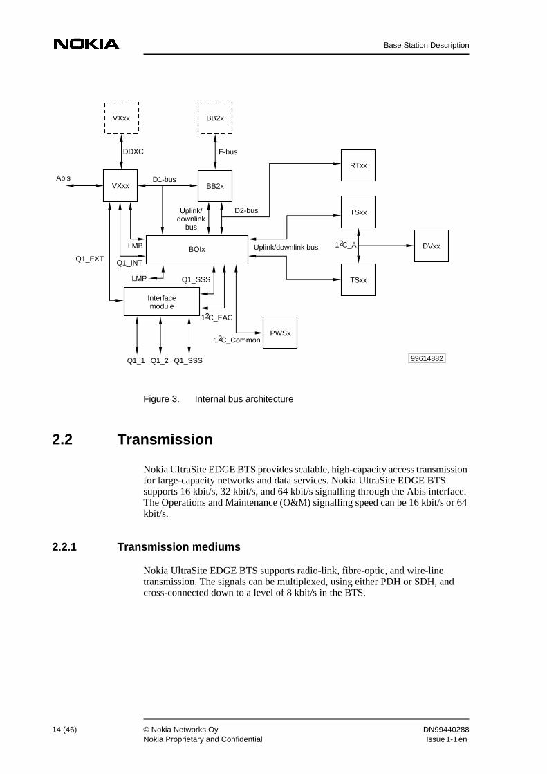
Nokia UltraSite EDGE BTS provides scalable, high-capacity access transmissionfor large-capacity networks and data services. Nokia UltraSite EDGE BTSsupports 16 kbit/s, 32 kbit/s, and 64 kbit/s signalling through the Abis interface.The Operations and Maintenance (O&M) signalling speed can be 16 kbit/s or 64kbit/s.
2.2.1 Transmission mediums
Nokia UltraSite EDGE BTS supports radio-link, fibre-optic, and wire-linetransmission. The signals can be multiplexed, using either PDH or SDH, andcross-connected down to a level of 8 kbit/s in the BTS.
The radio-link transmission unit for Nokia UltraSite EDGE BTS is the FXC RRIunit. The proprietary Nokia Flexbus, a coaxial cable, is available for transmissionbetween the microwave indoor unit and the outdoor unit.
Nokia Flexbus carries as much as 16 x 2 Mbit/s in both directions, and it alsocarries power for the outdoor unit. It is compatible with Nokia FlexiHopperMicrowave Radio and Nokia MetroHopper Radio, and it can also connect BTSsor transmission nodes at the site. The maximum cable length is 300 meters.
Fibre-optic transmission
The fibre-optic transmission units for Nokia UltraSite EDGE BTS are the FXCSTM-1 and FXC Bridge (always used together). The FXC STM-1 unit uses astandard SDH optical STM-1 interface, which can carry 63 x 2 Mbit/s.
Wire-line transmission
Cellular Access networks have been based mainly on the E1 (ETSI) and T1(ANSI) standards. E1 capacity is 2 Mbit/s; T1 capacity is 1.5 Mbit/s.
Nokia UltraSite EDGE BTS supports those standards with the following wire-linetransmission units:
• FC E1/T1
• FXC E1
• FXC E1/T1
2.2.2 Network topologies
Nokia UltraSite EDGE BTS supports all network topologies directly — loop,chain, star, point-to-point, and mesh. Separate transmission nodes are notnecessary. The BTS cabinet can hold as many as 4 integrated transmission units.
There can be 8 microwave connections in a single-cabinet Nokia UltraSite EDGEBTS and 20 in connections a 3-cabinet site. The transmission can be directlyconnected to Nokia MetroSite GSM BTS through Nokia MetroHopper Radio orNokia FlexiHopper Microwave Radio. Grooming at the BTS further optimizestransmission capacity.
Each BTS cabinet using FXC transmission units can provide add-drop capacityto other sites. The integrated transmission can groom traffic and serve as a PDHloop master. Cross-connections down to 8 k granularity and grooming at the BTSfurther optimise transmission capacity.
One BTS cabinet can provide a Flexbus connection for up to 8 NokiaMetroHopper Radios or Nokia FlexiHopper Microwave Radios, without anyadditional transmission equipment like radio indoor units. With FXC E1/T1 units,the corresponding number of interfaces is 16.
One FXC STM-1 unit has two STM-1 interfaces, each with 63 x 2 Mbit/s. Theunit can be used as an interface to a fibre-optic network or as an indoor unit forNokia UltraHopper Microwave Radio.
The number of connections can be increased when new cabinets are installed.However, the cabinets must be interconnected. The preferred solution forinterconnecting cabinets is Flexbus. Connecting two cabinets requires oneFlexbus interface in each cabinet. Multiple cabinets are connected to the firstcabinet.
Flexbus is used to interconnect the cabinets when a total add-drop capacity of 16x 2 Mbit/s is sufficent. When more capacity is needed, the FXC STM-1transmission can be chained through multiple cabinets for an add-drop capacityof 21 x 2 Mbit/s per cabinet. The FXC STM-1 occupies two slots (FXC STM-1and FXC Bridge units), leaving space for two other transmission units per cabinet.
A co-located Nokia Talk-family BTS can be connected to Nokia UltraSite EDGEBTS using the integrated E1/T1 interface or Flexbus. During the upgrade phase,Nokia Talk-family transmission interface towards the BSC can be used to provideAbis for Nokia UltraSite EDGE BTS. This, however, limits the capacity andexpandability of the BTS. Therefore, it is recommended that the Abis interfacesare connected through Nokia UltraSite EDGE BTS.
The choice among topologies depends mainly on the requirements fortransmission media and availability. The loop topology is the most reliable,providing excellent protection against equipment failures and radio-link fading.
Figure 5. Nokia UltraSite star and chain topologies
2.2.3 Cross-connections
Different transmission nodes support different cross-connection granularities andconnection types in GSM transmission networks. The BTS access networksnormally use 16 kbit/s for signalling and traffic. To fill higher-level transmissionpipes, the nodes must be able to make cross-connections on the 16 kbit/s level.
Nokia UltraSite EDGE BTS can handle the most important cross-connectiongranularities of:
• VC-4 (virtual container inside STM-1), capacity 63 x VC-12 (in laterreleases)
2.2.4 Protection
There are several complementary ways of protecting transmission againstproblems such as cable cuts, radio-link fading, and faults in the equipment.
Equipment protection
Equipment protection is used to ensure transmission regardless of faults in theequipment. This means that redundancy is built at the equipment level.
The Hot Standby (HSB) equipment protection for Nokia FlexiHopper MicrowaveRadio can be implemented with either one (FIU19, FXC RRI) or two (FIU19only) indoor units.
Protection of an FXC STM-1 unit can be implemented by installing a redundantFXC STM-1 unit. In the case of a fault in the operating unit or a forced switch bythe management function, the redundant, protecting unit becomes the primaryunit. This changeover is non-reverting.
Path protection
In general path protection, diverse paths for the traffic are configured to protecttraffic against faults. Nokia UltraSite EDGE BTS supports the 1+1 pathprotection where the traffic is sent in two paths simultaneously, and the protectionswitching is done entirely at the receiving end. Nokia UltraSite EDGE BTS doesnot provide support for the 1:1 and 1:N path protection methods.
The SDH multiplexing structure enables efficient path protection schemes. Singlemultiplexer sections as well as VC paths over several multiplexer sections can beprotected independently. The multiplexer sections may contain severalregenerator sections.
The FXC STM-1 units configured as Add/Drop Multiplexer (ADM) are capableof VC-12 level SNC/I (inherently monitored sub-network connection) protection.In multiplexer section protection the FXC STM-1 uses the single-ended switchingmode where both directions of transmission operate independently.
Loop protection
For connection protection to be efficient, diverse routes for the paths are needed.Loop or ring network structures are the most appropriate for this purpose. Loopsare a very efficient way to protect against failures in transmission path andequipment.
PDH loops with Nokia elements are implemented by a Nokia proprietary master-slave principle. The transmission direction in the loop is selected by using specialpilot bits. The pilot bits can be configured to be used as any bit in the 2 Mbit/ssignal. The loop master sends the pilot bits and thus controls the transmissiondirection of the loop.
SDH equipment provides efficient add/drop multiplexers without separate up anddown multiplexing. The ADMs can be used efficiently to provide automaticallyprotected transmission loops. The FXC STM-1 unit has two STM-1 interfaceswhich enables easy loop implementation. In later releases, FXC STM-1 can beused for interconnecting two loops.
2.3 Related software
The following Nokia software (SW) applications relate to Nokia UltraSite EDGEBTS:
• Network management SW
• Nokia SiteWizard
2.3.1 Network management SW
Nokia NMS/2000 SW in the Network Management System (NMS) manages theentire GSM network, including Nokia UltraSite EDGE BTS, through the BSC.This remote SW minimises the need for on-site BTS management.
Nokia NMS/2000 SW incorporates a full range of functions — from fault,performance, and configuration management to transmission, trouble, andsecurity management. For more information, refer to Nokia NMS documentation.
Nokia UltraSite EDGE BTS is delivered with factory-defined SW settings.
2.3.2 Nokia SiteWizard
Nokia SiteWizard manages Nokia UltraSite EDGE BTS on site. NokiaSiteWizard is a 32-bit application with a graphical user interface. It runs underWindows NT 4.0, Windows 95, or Windows 98.
Nokia UltraSite EDGE BTS SW includes an autodetection feature thatautomatically identifies the active BTS hardware. This feature saves time incommissioning by reducing the number of required system-data entries. NokiaSiteWizard displays this information.
Support for transmission autoconfiguration
Nokia UltraSite EDGE BTS SW supports Nokia Autoconfiguration, a feature thatautomatically integrates the BTS into the GSM network.
Advanced BTS diagnostics and alarm management
Nokia UltraSite EDGE BTS features an advanced BTS diagnostics system thatconsiderably reduces the number of alarms. This system makes alarm informationeasily accessible and understandable.
Commissioning Wizard and Configuration Wizard
Commissioning Wizard and Configuration Wizard display menus thatcorrespond to the steps for commissioning the BTS. The steps include:
• Site Configuration File
• Transmission Configuration
• Setting EACs
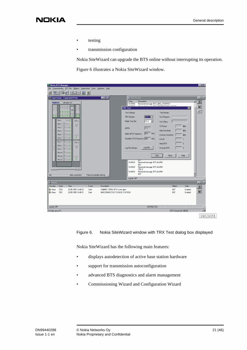
• Testing
• Log Files
• Reports
2.3.3 Software updates
Nokia UltraSite EDGE BTS can store two SW packages in its memory. SW isloaded either locally with Nokia SiteWizard or remotely from the BSC or theNMS (through the BSC). The operator can download Nokia UltraSite EDGE BTSSW as a background operation (without interrupting the BTS operation) and canactivate the new software at any time.
Updates to Nokia UltraSite EDGE BTS SW are delivered in Nokia ElectronicDocumentation (NED) CD-ROM package. This package contains the currentversions of the BTS SW and Nokia SiteWizard. For more information on NokiaUltraSite EDGE BTS SW, refer to Nokia UltraSite EDGE BTS PU1.0 SoftwarePre-release Binder.
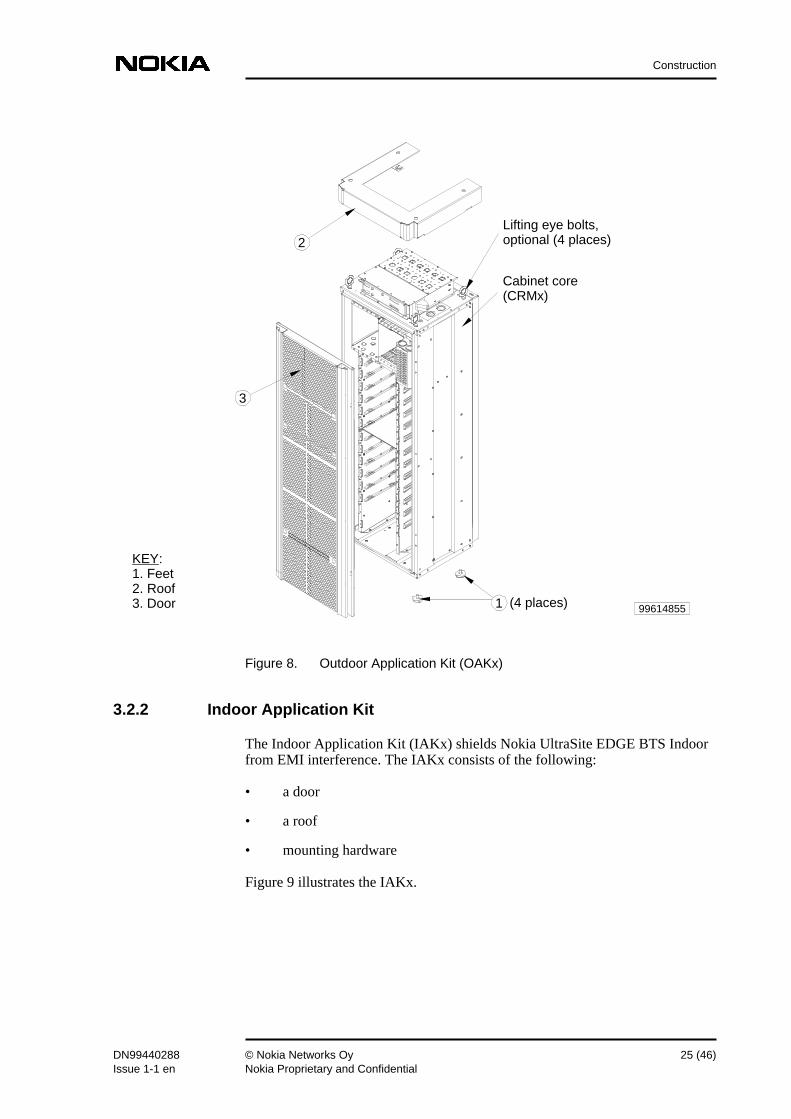
3 ConstructionNokia UltraSite EDGE BTS Outdoor and Indoor cabinets are constructed onidentical cabinet cores. The main difference between the cabinets is in theexternal application kits.
3.1 Cabinet core
Nokia UltraSite EDGE BTS features a self-standing cabinet core (CRMx) withunit guides.
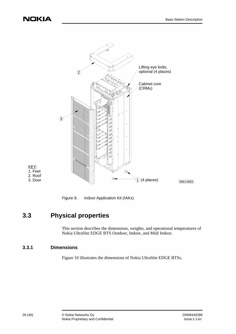
The application kits are sets of metal panels that shield the BTS fromelectromagnetic interference (EMI). The following kits are available:
• Outdoor Application Kit (OAKx)
• Indoor Application Kit (IAKx)
3.2.1 Outdoor Application Kit
In addition to its EMI protection, the Outdoor Application Kit (OAKx) protectsthe Outdoor BTS against water, snow, and solid foreign objects. The OAKx isweatherproof to IP 55 standards.
The OAKx consists of the following:
• a door, with a Cabinet Cooling Fan for additional cooling
4 UnitsThis chapter describes the units and unit versions available for Nokia UltraSiteEDGE BTS Indoor, Outdoor, and Midi Indoor. It also contains brief overviews ofthe units.
4.1 Unit availability
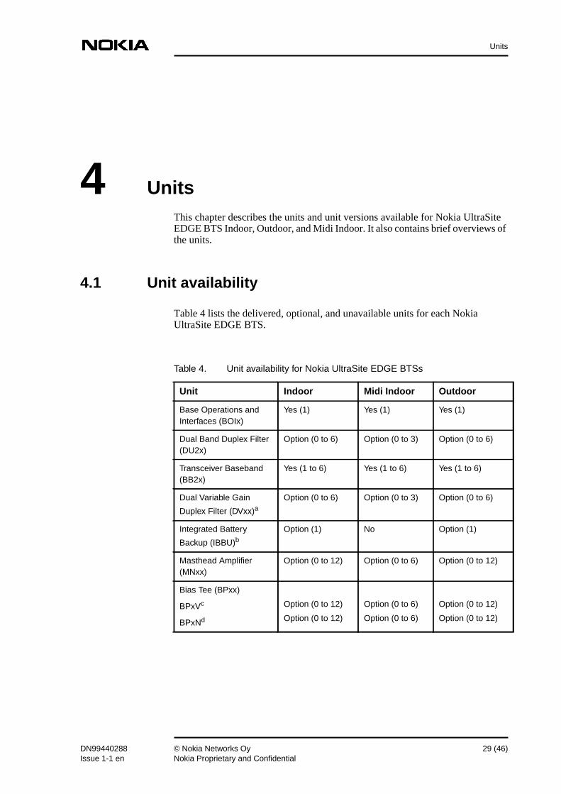
Table 4 lists the delivered, optional, and unavailable units for each NokiaUltraSite EDGE BTS.
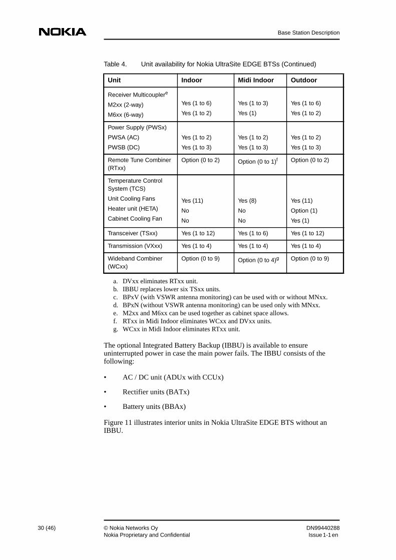
Table 4. Unit availability for Nokia UltraSite EDGE BTSs
Unit Indoor Midi Indoor Outdoor
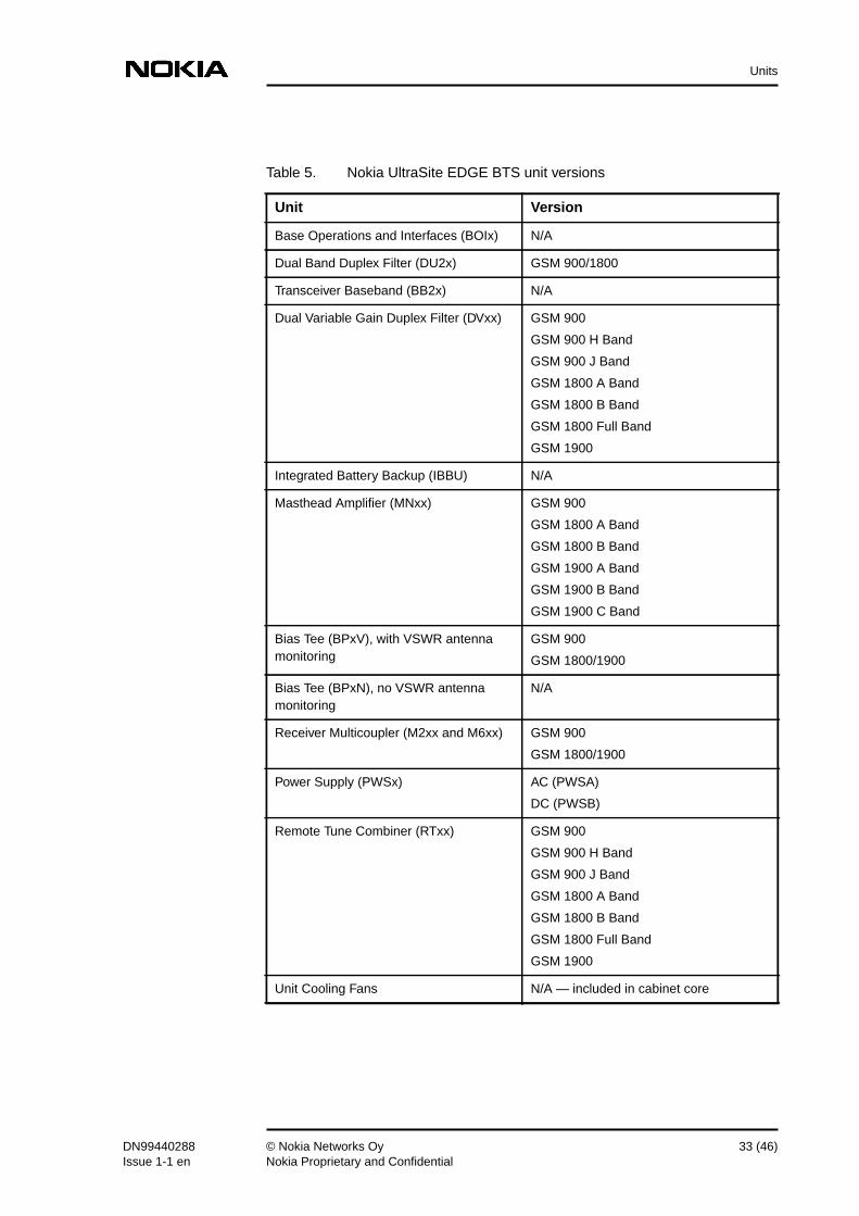
Base Operations andInterfaces (BOIx)
Yes (1) Yes (1) Yes (1)
Dual Band Duplex Filter(DU2x)
Option (0 to 6) Option (0 to 3) Option (0 to 6)
Transceiver Baseband(BB2x)
Yes (1 to 6) Yes (1 to 6) Yes (1 to 6)
Dual Variable Gain
Duplex Filter (DVxx)aOption (0 to 6) Option (0 to 3) Option (0 to 6)
The optional Integrated Battery Backup (IBBU) is available to ensureuninterrupted power in case the main power fails. The IBBU consists of thefollowing:
• AC / DC unit (ADUx with CCUx)
• Rectifier units (BATx)
• Battery units (BBAx)
Figure 11 illustrates interior units in Nokia UltraSite EDGE BTS without anIBBU.
Receiver Multicouplere
M2xx (2-way)
M6xx (6-way)
Yes (1 to 6)
Yes (1 to 2)
Yes (1 to 3)
Yes (1)
Yes (1 to 6)
Yes (1 to 2)
Power Supply (PWSx)
PWSA (AC)
PWSB (DC)
Yes (1 to 2)
Yes (1 to 3)
Yes (1 to 2)
Yes (1 to 3)
Yes (1 to 2)
Yes (1 to 3)
Remote Tune Combiner(RTxx)
Option (0 to 2) Option (0 to 1)f Option (0 to 2)
Temperature ControlSystem (TCS)
Unit Cooling Fans
Heater unit (HETA)
Cabinet Cooling Fan
Yes (11)
No
No
Yes (8)
No
No
Yes (11)
Option (1)
Yes (1)
Transceiver (TSxx) Yes (1 to 12) Yes (1 to 6) Yes (1 to 12)
Transmission (VXxx) Yes (1 to 4) Yes (1 to 4) Yes (1 to 4)
Wideband Combiner(WCxx)
Option (0 to 9) Option (0 to 4)g Option (0 to 9)
a. DVxx eliminates RTxx unit.b. IBBU replaces lower six TSxx units.c. BPxV (with VSWR antenna monitoring) can be used with or without MNxx.d. BPxN (without VSWR antenna monitoring) can be used only with MNxx.e. M2xx and M6xx can be used together as cabinet space allows.f. RTxx in Midi Indoor eliminates WCxx and DVxx units.g. WCxx in Midi Indoor eliminates RTxx unit.
Table 4. Unit availability for Nokia UltraSite EDGE BTSs (Continued)
Figure 11. Nokia UltraSite EDGE BTS interior units (without IBBU)
Figure 12 illustrates interior units in Nokia UltraSite EDGE BTS with an IBBU.
KEY:
1 Transceiver unit (TSxx)2 2-way Receiver Multicoupler unit (M2xx)3 Transceiver Baseband unit (BB2x)4 Base Operations and Interfaces unit (BOIx)5 Transmission unit (VXxx)6 Wideband Combiner unit (WCxx)7 Dual Variable Gain Duplex Filter unit (DVxx)8 DC/DC Power Supply unit (PWSB)9 6-way Receiver Multicoupler unit (M6xx)10 Remote Tune Combiner unit (RTxx)11 AC/DC Power Supply unit (PWSA)12 Bias Tee unit (BPxx)13 Dual Band Duplex Filter unit (DU2x)
Figure 12. Nokia UltraSite EDGE BTS interior units (with IBBU)
4.2 Unit versions
Table 5 lists the unit versions for Nokia UltraSite EDGE BTS.
KEY:
1 Transceiver unit (TSxx)2 2-way Receiver Multicoupler unit (M2xx)3 Transceiver Baseband unit (BB2x)4 Base Operations and Interfaces unit (BOIx)5 Transmission unit (VXxx)6 Dual Variable Gain Duplex Filter unit (DVxx)7 DC/DC Power Supply unit (PWSB)8 Rectifier unit (BATx)9 Battery unit for IBBU (BBAx)10 AC/DC Distribution unit for IBBU (ADUx)11 Cabinet Control unit (CCUx)12 Bias Tee unit (BPxx)13 Dual Band Duplex Filter unit (DU2x)
This section presents a brief overview of each unit in Nokia UltraSite EDGE BTS.For detailed information about a unit, see the unit’s individual description in thismanual.
4.3.1 Base Operations and Interfaces unit
The Base Operations and Interfaces unit (BOIx) handles the control functionscommon to all other units in the BTS. These functions include:
• BTS initialisation and self-testing
• configuration
• O&M functions
• software downloads
• main clock functions
• timing functions
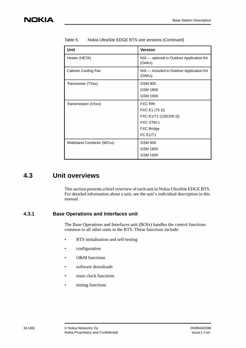
Heater (HETA) N/A — optional in Outdoor Application Kit(OAKx)
Cabinet Cooling Fan N/A — included in Outdoor Application Kit(OAKx)
Transceiver (TSxx) GSM 900
GSM 1800
GSM 1900
Transmission (VXxx) FXC RRI
FXC E1 (75 Ω)
FXC E1/T1 (120/100 Ω)
FXC STM-1
FXC Bridge
FC E1/T1
Wideband Combiner (WCxx) GSM 900
GSM 1800
GSM 1900
Table 5. Nokia UltraSite EDGE BTS unit versions (Continued)
• collection and management of external and internal alarms
• message delivery to the BSC (through the VXxx unit)
• cabinet control
4.3.2 Dual Band Duplex Filter unit
The Dual Band Duplex Filter unit (DU2x) combines outputs from GSM 900 andGSM 1800 DVxx or RTxx units into one antenna feeder.
4.3.3 Transceiver Baseband unit
The Transceiver Baseband unit (BB2x) is a digital signal processing board,consisting of two independent baseband modules; each module functionsindependently for its own TSxx unit. The BB2x also controls frequency hopping.
4.3.4 Dual Variable Gain Duplex Filter unit
The Dual Variable Gain Duplex Filter unit (DVxx) performs duplex operation ofTX and RX signals into a common antenna, and provides filtering andamplification for main and diversity receiver signals before they go through theM2xx or M6xx unit to the TSxx unit. The DVxx unit contains a variable-gainLNA for optimal amplification of the receive signal, with or without the optionalMasthead Amplifier.
4.3.5 Integrated Battery Backup
The optional Integrated Battery Backup (IBBU) ensures a continual power supplyif the main AC power fails. The IBBU can produce power for as many as 18 TSxxunits in two BTS cabinets. It occupies the bottom of Nokia UltraSite EDGE BTS.
The IBBU consists of the following:
• AC / DC unit (ADUx with CCUx)
• Rectifier units (BATx)
• Battery units (BBAx)
For more information about the IBBU, refer to Nokia UltraSite Support ProductOverview.
The Masthead Amplifier unit (MNxx) delivers 33 dB RX gain in GSM 1800/GSM 1900 units and 32 dB RX gain in GSM 900 units, low RX noise figure(improved RX sensitivity and signal-to-noise ratio) and low TX loss in a compact,low volume, light-weight sealed enclosure. To use the MNxx, the Bias Tee unitis required.
Bias Tee unit
The Bias Tee unit (BPxx) provides DC power, through an RF cable, to the MNxxunit. There are two versions of the BPxx unit:
• BPxV — Bias Tee with Voltage Standing Wave Ratio (VSWR) antennamonitoring, which checks the antenna line’s condition and gives an alarmif the VSWR value exceeds the limit
• BPxN — Bias Tee without VSWR antenna monitoring
The BPxN (without VSWR) is used solely with the MNxx, while the BPxV (withVSWR) can be used with or without the MNxx.
4.3.7 Receiver Multicoupler unit
The Receiver Multicoupler unit (M2xx and M6xx) distributes RX signals to TRXRF units. The 2-way unit (M2xx) is used in most WCxx or combining by-passconfigurations. The 6-way unit (M6xx) is always used with an RTxx unit. Oneunit performs signal splitting for both main and diversity branches.
4.3.8 Power Supply unit
The Power Supply unit (PWSx) converts input AC or DC voltage to the differentDC voltages required for the various BTS units. Then it distributes theappropriate voltages through the backplanes to the units — except for the optionalHeater unit (HETA), which receives its voltage from the AC mains through thepower filter module. The PWSx unit also supplies power for the MastheadAmplifier unit (MNxx).
Nokia UltraSite EDGE BTS can hold two AC Power Supply units (PWSA) orthree DC Power Supply units (PWSB). The PWSA supports full redundancy foras many as six TSxx units. The PWSB supports full redundancy for as many as12 TSxx units.
The Remote Tune Combiner (RTxx) combines up to six transmitter outputs intoone antenna. It also provides filtering and amplification for main and diversityreceiver (RX) signals before they go through the M2xx or M6xx unit to the TSxxunit.
The RTxx unit contains a variable-gain LNA for optimal amplification of thereceive signal. The high-gain LNA is fixed, and is used without the optionalMNxx unit. The low-gain LNA is variable, and is used only with the MNxx unit;the low-gain LNA is set according to antenna cable attenuation values.
A duplexer is built into the RTxx, so no DVxx unit is required.
4.3.10 Temperature Control System
Unit Cooling Fans
The Unit Cooling Fans are included in the cabinet core. The BOIx unit controlsthe fan units according to temperature information from other units. The coolingis performed by adjusting the rotation speed of the fans. Smooth speed variationsalso minimise the noise generated by the fan units.
Heater unit
The optional Heater unit (HETA) is needed in Nokia UltraSite EDGE BTSOutdoor to cold-start the BTS when operating in temperatures between -10 and -33°C (+14 to -27°F). It will also maintain interior cabinet temperature duringextreme cold operation.
Cabinet Cooling Fan
The Cabinet Cooling Fan is included in the Outdoor Application Kit (OAKx), andis mounted in the cabinet door.
4.3.11 Transceiver unit
The Transceiver unit (TSxx) consists of one transmitter, one main receiver, andone diversity receiver.
4.3.12 Transmission unit
The Transmission unit (VXxx) connects Nokia UltraSite EDGE BTSs with eachother and to the rest of the network.
Transmission units are available for the following mediums:
The FXC RRI unit is the radio-link transmission unit for Nokia UltraSite EDGEBTS. The FXC RRI supports the following:
• two Flexbus connections (coaxial cable), each at 16 x 2 Mbit/s
• grooming
• branching
• loop protection
• cross-connection on 8 kbit/s level
Flexbus connects FXC RRI transmission units to Nokia FlexiHopper MicrowaveRadio or Nokia MetroHopper Radio. When multiple BTS cabinets are located atthe same site, a one-cable Flexbus (provided by RRI units) can connecttransmission units between two cabinets.
The FXC RRI operates as a repeater and interconnects Nokia UltraSite EDGEBTS and the BSC using point-to-point, chain, star, or loop networkconfigurations.
For more information on UltraSite-compatible radios, refer to Nokia FlexiHopperMicrowave Radio Product Overview and Nokia MetroHopper Radio ProductOverview.
Fibre-optic transmission
The following fibre-optic transmission units are available for Nokia UltraSiteEDGE BTS:
• FXC STM-1: two standard STM-1 (155 Mbit/s) short-haul opticalinterfaces and power feed for two Nokia UltraHopper radios. Performs themain SDH functions, including the SDH node clock, SDH cross-connect(VC-3, VC-2, VC-12 level), and management functions
• FXC Bridge: Bridge for the signals between the SDH part and the PDHcross-connect of the FXC units. Includes Q1 management and crossconnection on 8 kbit/s, 16 kbit/s, 32 kbit/s, 64 kbit/s, and n x 64 kbit/s level
The FXC STM-1 and FXC Bridge transmission units are always used together;each unit occupies one transmission slot. The FXC STM-1 unit can be connectedto any SDH equipment through the standard STM-1 optical interfaces.
The FXC STM-1 and FXC Bridge operate as a repeater/branching point andinterconnect Nokia UltraSite EDGE BTS and the BSC using point-to-point,chain, star, or loop network configurations.
For more information on UltraSite compatible SDH radios, refer to NokiaUltraHopper Microwave Radio Product Overview.
Wire-line transmission
The following wire-line transmission units are available for Nokia UltraSiteEDGE BTS:
• FC E1/T1: 1 x 2 Mbit/s (E1) or 1 x 1.5 Mbit/s (T1) PCM connection, onecoaxial 75-ohm TX and one coaxial 75-ohm RX connector for E1 use, onetwisted pair 120-/100-ohm TX/RX interface connector for either E1 or T1use
• FXC E1: 4 x 2 Mbit/s (E1) PCM connections, four coaxial 75-ohm TX andfour coaxial 75-ohm RX connectors for E1 use, grooming, branching, andloop protection support, cross-connection down to 8 kbit/s level
• FXC E1/T1: 4 x 2 Mbit/s (E1) or 4 x 1.5 Mbit/s (T1) PCM connections, fourtwisted pair 120-/100-ohm TX/RX interface connectors for either E1 or T1use, grooming, branching, and loop protection support, cross-connectiondown to 8 kbit/s level. Interfaces can be configured independently eitherE1 or T1 mode
The FC E1/T1 operates as the termination point in a star or chain topologynetwork. The FXC E1 and FXC E1/T1 operate as branching points andinterconnect Nokia UltraSite EDGE BTS and the BSC using point-to-point,chain, star, or loop network configurations.
4.3.13 Wideband Combiner unit
The Wideband Combiner (WCxx) combines two transmitter outputs into one.When using the WCxx, the DVxx unit is required.
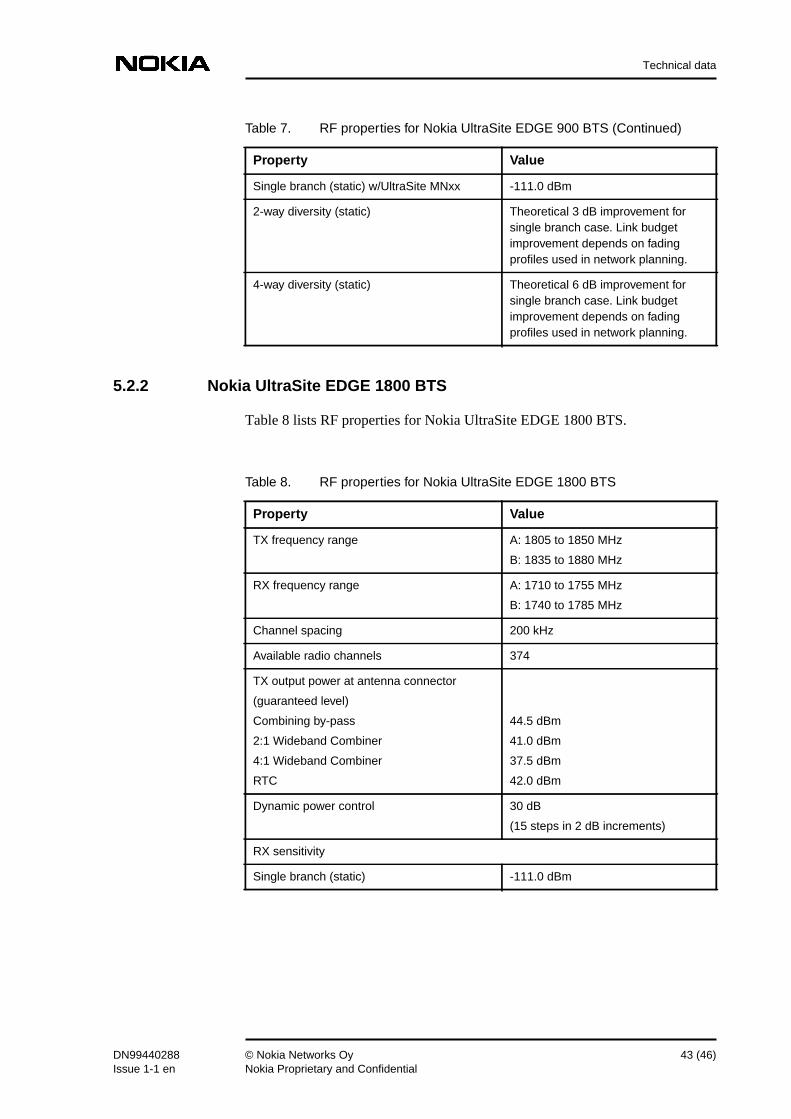
Table 8 lists RF properties for Nokia UltraSite EDGE 1800 BTS.
Single branch (static) w/UltraSite MNxx -111.0 dBm
2-way diversity (static) Theoretical 3 dB improvement forsingle branch case. Link budgetimprovement depends on fadingprofiles used in network planning.
4-way diversity (static) Theoretical 6 dB improvement forsingle branch case. Link budgetimprovement depends on fadingprofiles used in network planning.
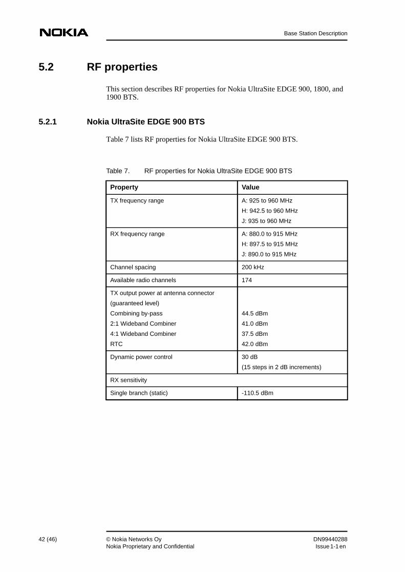
Table 7. RF properties for Nokia UltraSite EDGE 900 BTS (Continued)
Property Value
Table 8. RF properties for Nokia UltraSite EDGE 1800 BTS
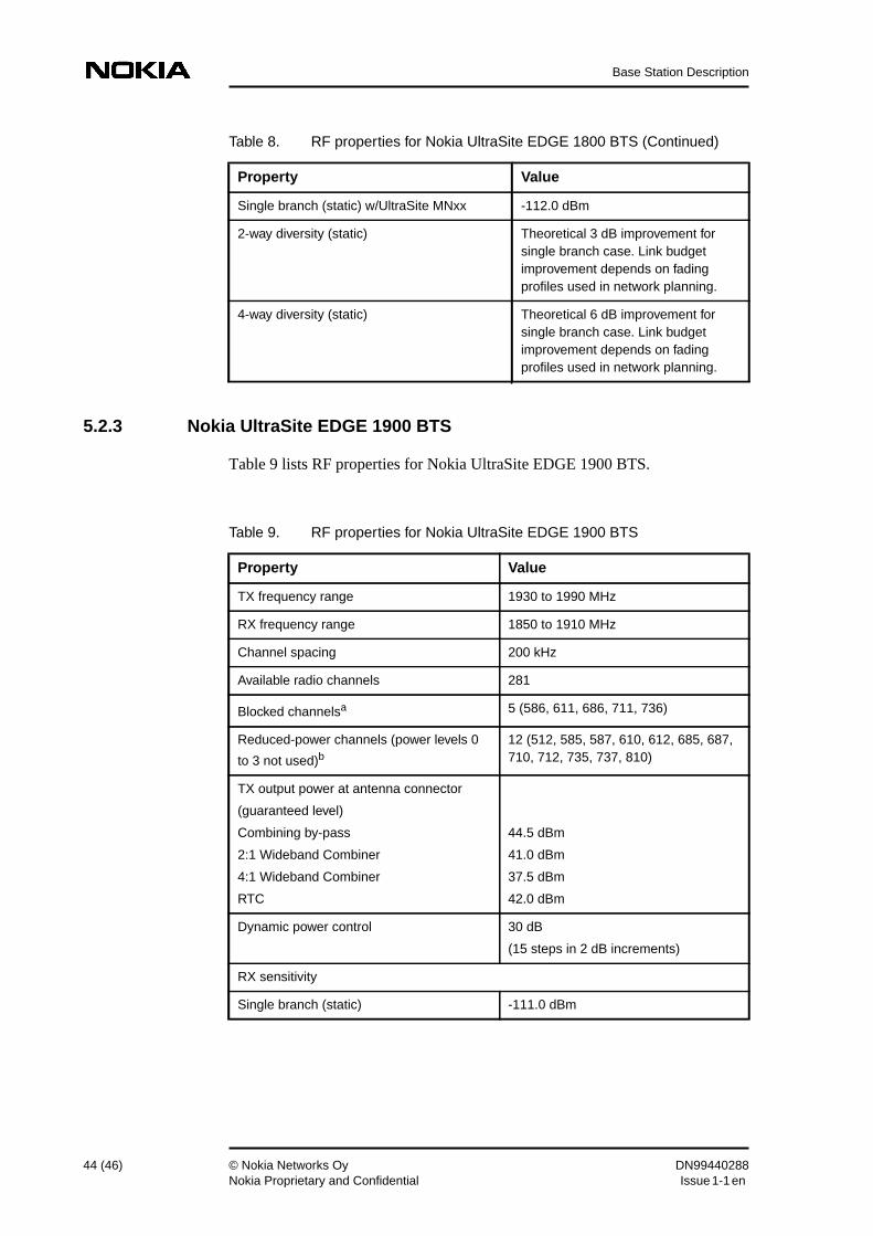
Table 9 lists RF properties for Nokia UltraSite EDGE 1900 BTS.
Single branch (static) w/UltraSite MNxx -112.0 dBm
2-way diversity (static) Theoretical 3 dB improvement forsingle branch case. Link budgetimprovement depends on fadingprofiles used in network planning.
4-way diversity (static) Theoretical 6 dB improvement forsingle branch case. Link budgetimprovement depends on fadingprofiles used in network planning.
Table 8. RF properties for Nokia UltraSite EDGE 1800 BTS (Continued)
Property Value
Table 9. RF properties for Nokia UltraSite EDGE 1900 BTS
Property Value
TX frequency range 1930 to 1990 MHz
RX frequency range 1850 to 1910 MHz
Channel spacing 200 kHz
Available radio channels 281
Blocked channelsa 5 (586, 611, 686, 711, 736)
Reduced-power channels (power levels 0
to 3 not used)b12 (512, 585, 587, 610, 612, 685, 687,710, 712, 735, 737, 810)
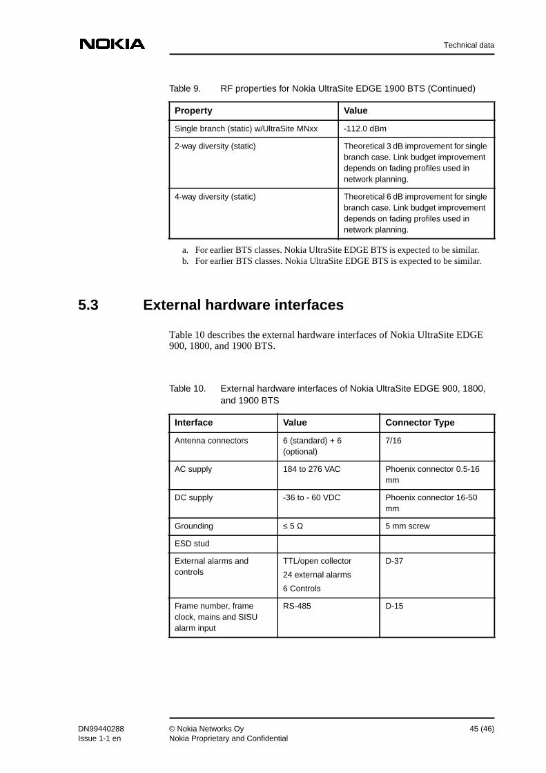
Table 10 describes the external hardware interfaces of Nokia UltraSite EDGE900, 1800, and 1900 BTS.
Single branch (static) w/UltraSite MNxx -112.0 dBm
2-way diversity (static) Theoretical 3 dB improvement for singlebranch case. Link budget improvementdepends on fading profiles used innetwork planning.
4-way diversity (static) Theoretical 6 dB improvement for singlebranch case. Link budget improvementdepends on fading profiles used innetwork planning.
a. For earlier BTS classes. Nokia UltraSite EDGE BTS is expected to be similar.b. For earlier BTS classes. Nokia UltraSite EDGE BTS is expected to be similar.
Table 9. RF properties for Nokia UltraSite EDGE 1900 BTS (Continued)
Property Value
Table 10. External hardware interfaces of Nokia UltraSite EDGE 900, 1800,and 1900 BTS
Interface Value Connector Type
Antenna connectors 6 (standard) + 6(optional)
7/16
AC supply 184 to 276 VAC Phoenix connector 0.5-16mm
DC supply -36 to - 60 VDC Phoenix connector 16-50mm
Grounding ≤ 5 Ω 5 mm screw
ESD stud
External alarms andcontrols
TTL/open collector
24 external alarms
6 Controls
D-37
Frame number, frameclock, mains and SISUalarm input