All covered components - Limited five years in residential applications, one year in non-residential applications.Refer to Lennox Limited Warranty Certificate included with each unit for additional details.
APPROVALSTested with matching air conditioners and heat pump units in the Lennox Research Laboratory environmental test room in accordance with AHRI Standard 210/240.Optional electric heaters are rated in accordance with US Department of Energy (DOE) test procedures and Federal Trade Commission (FTC) labeling regulations.Air handlers are ETL Listed to US and Canadian safety standards and components within are bonded for grounding to meet safety standards for servicing required by CEC and NEC.ISO 9001 Registered Manufacturing Quality System.
APPLICATIONS1.5 to 5 ton nominal sizes.Upflow or horizontal applications.Compact cabinet height for upflow, horizontal-left or horizontal-right applications.NOTE - Not available for downflow applications.Utility room, alcove, closet, crawl space, basement or attic installation.CBX25UHV models are applicable to R-410A expansion valve systems in cooling applications and check and expansion valve systems in heat pump applications.See bulletins in section Air Conditioners for cooling capacities.See bulletins in section Heat Pump Outdoor Units for cooling and heating capacities.Optional field installed electric heaters available in several sizes for additive heating capacity.
Zoning ApplicationsUnits can be used with certain zoning systems.
A
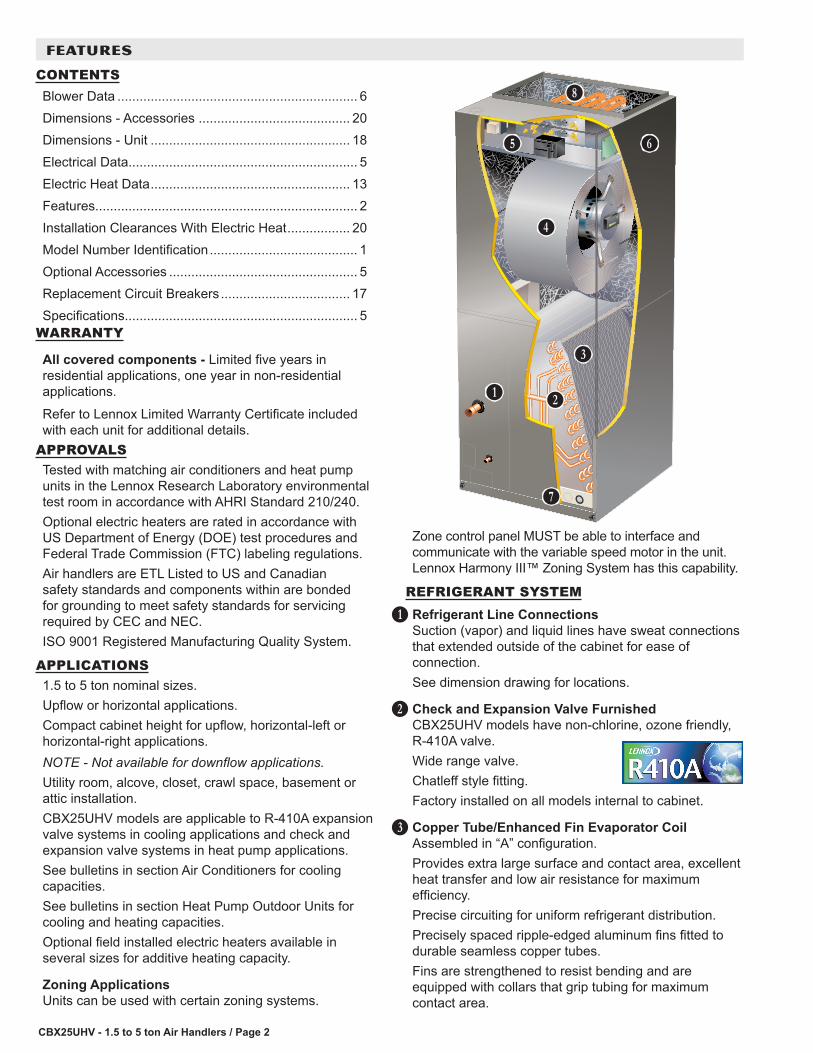
Zone control panel MUST be able to interface and communicate with the variable speed motor in the unit. Lennox Harmony III™ Zoning System has this capability.
REFRIGERANT SYSTEMRefrigerant Line ConnectionsSuction (vapor) and liquid lines have sweat connections that extended outside of the cabinet for ease of connection.See dimension drawing for locations.
Check and Expansion Valve FurnishedCBX25UHV models have non-chlorine, ozone friendly, R-410A valve.Wide range valve.Chatleff style fitting.Factory installed on all models internal to cabinet.
Copper Tube/Enhanced Fin Evaporator CoilAssembled in “A” configuration.Provides extra large surface and contact area, excellent heat transfer and low air resistance for maximum efficiency.Precise circuiting for uniform refrigerant distribution.Precisely spaced ripple-edged aluminum fins fitted to durable seamless copper tubes.Fins are strengthened to resist bending and are equipped with collars that grip tubing for maximum contact area.
B
C
D
B C
D
E
F G
H
I
FEATURES
CONTENTSBlower Data ................................................................. 6Dimensions - Accessories ......................................... 20Dimensions - Unit ...................................................... 18Electrical Data.............................................................. 5Electric Heat Data ...................................................... 13Features....................................................................... 2Installation Clearances With Electric Heat ................. 20Model Number Identification ........................................ 1Optional Accessories ................................................... 5Replacement Circuit Breakers ................................... 17Specifications............................................................... 5
CBX25UHV - 1.5 to 5 ton Air Handlers / Page 3
REFRIGERANT SYSTEM (continued)Lanced fins provide maximum exposure of fin surface to air stream.Long life copper tubing is easy to service.Rifled tubing provides superior heat transfer.Flared shoulder tubing joints and silver soldering provide tight, leakproof joints.Coil thoroughly factory tested under high pressure to insure leakproof construction.
BLOWERProgrammable Multi-Speed Blower MotorHigh efficiency multi-speed blower motor maintains specified air volumes up to a maximum of 0.8 in. w.g. total external static.Programmable multi-speed operation is achieved by the use of an ECM (Electronically Commutated Motor) motor.Allows cooling ramping profiles (field selectable) for enhanced dehumidification.Motor accelerates and decelerates gradually, reducing start-up and shut-down sound.Leadless blower motor features simple plug-in connections.Motor is controlled by BDC3 Electronic Blower Control that allows blower to operate at two of eight air volumes or speeds available.Blower speeds may be field selected on blower control depending on size of air handler and air volume desired.See Blower Data tables.
Blower AssemblyEach blower is statically and dynamically balanced as an assembly before installation in the unit.Blower motor is resiliently mounted to blower assembly.Blower slides out of cabinet for servicing.
CONTROLSBDC3 Electronic Blower ControlControls evaporator humidity by controlling blower and compressor staging on two-stage outdoor units.Two Stages - HEAT and COOL (with four different air volume selections for each) are made by simple jumper pins on board.ADJUST jumper pin allows approximately 10% higher, normal or 10% lower motor speed selection within HEAT and COOL speeds selected for fine tuning air volume.DELAY jumper pin allows selection of four different blower motor de-humidification profiles during cooling mode:
Option 1 - Motor runs at 100% of capacity until demand met. Once demand is met, motor ramps down to stop.
E
Option 2 - Motor runs at 100% until demand is met. Once demand is satisfied, motor runs at 100% for 60 seconds then ramps down to stop.Option 3 - Motor runs at 82% of capacity for approximately 7-1/2 minutes, then 100% capacity (if needed) until demand is satisfied. Once demand is met, motor ramps down to stop.Option 4 - Motor runs at 50% capacity for 30 seconds, then 82% capacity for approximately 7-1/2 minutes. If demand is not satisfied, motor runs at 100% capacity until demand is met. Once demand is met, motor runs at 50% capacity for 30 seconds, then ramps down to stop.Control has two diagnostic indicator lights, “CFM” and “RUN”, to assist in servicing.Accessory relay terminals (24V) provide connections for power humidifiers or powered air cleaners.Control is factory installed in the unit control box.Transformer and Blower Relay for Electric Heat24 volt transformer and blower relay for electric heat furnished as standard.Factory installed in the unit control box.
Optional Accessories
ThermostatSee Thermostat bulletins in Controls section and Lennox Price Book for a complete list of thermostats.
CABINETConstructed of heavy gauge galvanized steel.Powder paint finish.Completely insulated with foil faced fiberglass insulation.Removable panels provide complete service access.Filter access door for easy filter replacement. Thumbscrews secure filter door.Electrical inlets provided in sides and top of cabinet. See dimension drawing for locations.Knock-outs in cabinet for drain connections for upflow (left and right) and horizontal applications. See dimension drawing.
Low Leakage CabinetAll models have less than 2% air leakage and meet ANSI/ASHRAE Standard 193-2010 “Method of Test for Determining the Air Tightness of HVAC Equipment.”
Upflow/Horizontal CapabilityShipped for upflow and horizontal left-hand discharge.May be field converted to horizontal right-hand air discharge by repositioning horizontal drain pan.NOTE - Not available for downflow applications.
F
G
FEATURES
CBX25UHV - 1.5 to 5 ton Air Handlers / Page 4
CABINET (continued)
Anti-Microbial Dual Position Drain PansAnti-Microbial additive resists growth of mold and mildew on drain pan which improves indoor air quality and reduces drain line blockage.Drain pans designed for upflow or horizontal applications.Deep, corrosion resistant high temperature engineered polymer drain pans have dual pipe drains. See dimension drawing.
Optional Accessories
Horizontal Support Frame KitProvides support of unit in horizontal applications.Consists of (2) 1 x 1-1/2 x 32-5/8 in. and (2) 1 x 3 x 53-7/8 in. painted heavy gauge cold rolled steel support channels with assembly and suspending holes.Bolts and nuts furnished for field assembly.Suspending rods must be field provided.
Side Return Unit Stand (Upflow Only)Raises unit 16 in. above floor for side return air duct connection.Eliminates need for wooden platform construction.All aluminum construction.Two adjustable frames fit all sizes.See Dimension Drawing.
Wall Hanging Bracket Kit (Upflow Only)Allows unit to be hung on wall at any height.Consists of heavy gauge steel support brackets (one for air handler unit, one for wall mount).Screws furnished for fastening one bracket to unit.Bolts for fastening one bracket to wall are field provided.
FILTERDisposable 1 inch filter is furnished.Filter rack furnished in cabinet for easy filter installation.See Specifications tables for filter sizes.
H
FEATURES
ELECTRICAL
Optional Accessories
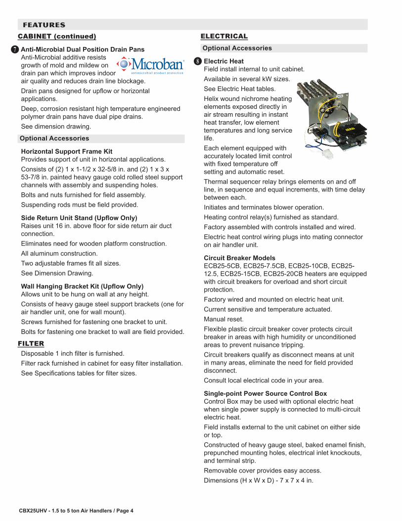
Electric HeatField install internal to unit cabinet.Available in several kW sizes.See Electric Heat tables.Helix wound nichrome heating elements exposed directly in air stream resulting in instant heat transfer, low element temperatures and long service life.Each element equipped with accurately located limit control with fixed temperature off setting and automatic reset.Thermal sequencer relay brings elements on and off line, in sequence and equal increments, with time delay between each.Initiates and terminates blower operation.Heating control relay(s) furnished as standard.Factory assembled with controls installed and wired.Electric heat control wiring plugs into mating connector on air handler unit.
Circuit Breaker ModelsECB25-5CB, ECB25-7.5CB, ECB25-10CB, ECB25-12.5, ECB25-15CB, ECB25-20CB heaters are equipped with circuit breakers for overload and short circuit protection.Factory wired and mounted on electric heat unit.Current sensitive and temperature actuated.Manual reset.Flexible plastic circuit breaker cover protects circuit breaker in areas with high humidity or unconditioned areas to prevent nuisance tripping.Circuit breakers qualify as disconnect means at unit in many areas, eliminate the need for field provided disconnect.Consult local electrical code in your area.
Single-point Power Source Control BoxControl Box may be used with optional electric heat when single power supply is connected to multi-circuit electric heat.Field installs external to the unit cabinet on either side or top.Constructed of heavy gauge steel, baked enamel finish, prepunched mounting holes, electrical inlet knockouts, and terminal strip.Removable cover provides easy access.Dimensions (H x W x D) - 7 x 7 x 4 in.
I
CBX25UHV - 1.5 to 5 ton Air Handlers / Page 5
SPECIFICATIONSGeneral Data
Model Number CBX25UHV-018 CBX25UHV-024 CBX25UHV-030 CBX25UHV-036Nominal tonnage 1.5 2 2.5 3
Connections Suction/Vapor line (o.d.) - in. sweat 3/4 3/4 7/8 7/8Liquid line (o.d.) - in. sweat 3/8 3/8 3/8 3/8
Blower Motor Full Load Amps 5.2 6.9 6.9Shipping Data -1 package - lbs. 163 186 1861 Disposable filter.2 HACR type circuit breaker or fuse.3 Refer to National or Canadian Electrical Code manual to determine wire, fuse and disconnect size requirements. Use wires suitable for at least 167°F.
OPTIONAL ACCESSORIES - ORDER SEPARATELYModel -018 -024
-030-036 -042
-048 -060
Horizontal Support Frame Kit 56J18 56J18 56J18 56J18
Side Return Unit Stand (Upflow Only) 45K31 45K32 45K32 45K32
Single-Point Power Source Control Box (for Electric Heat) 21H39 21H39 21H39 21H39
Wall Hanging Bracket Kit (Upflow Only) 45K30 45K30 45K30 45K30NOTE - Not available for downflow applications.
CBX25UHV - 1.5 to 5 ton Air Handlers / Page 6
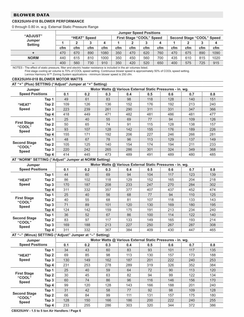
BLOWER DATACBX25UHV-018 BLOWER PERFORMANCE0 through 0.80 in. w.g. External Static Pressure Range
“ADJUST” Jumper Setting
Jumper Speed Positions“HEAT” Speed First Stage “COOL” Speed Second Stage “COOL” Speed
– 400 560 730 910 350 420 520 650 400 575 725 915NOTES - The effect of static pressure, filter and electric heater resistance is included in the air volumes listed.
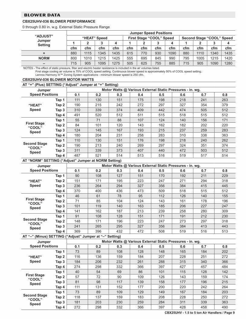
First stage cooling air volume is 70% of COOL speed setting. Continuous blower speed is approximately 50% of COOL speed setting. Lennox Harmony III™ Zoning System applications - minimum blower speed is 250 cfm.
CBX25UHV-018 BLOWER MOTOR WATTSAT “+” (Plus) SETTING (“Adjust” Jumper at “+” Setting)
Jumper Speed Positions
Motor Watts @ Various External Static Pressures - in. wg.0.1 0.2 0.3 0.4 0.5 0.6 0.7 0.8
– 410 550 720 900 300 405 505 650 390 545 740 930NOTES - The effect of static pressure, filter and electric heater resistance is included in the air volumes listed.
First stage cooling air volume is 70% of COOL speed setting. Continuous blower speed is approximately 50% of COOL speed setting. Lennox Harmony III™ Zoning System applications - minimum blower speed is 250 cfm.
CBX25UHV-024 BLOWER MOTOR WATTSAT “+” (Plus) SETTING (“Adjust” Jumper at “+” Setting)
Jumper Speed Positions
Motor Watts @ Various External Static Pressures - in. wg.0.1 0.2 0.3 0.4 0.5 0.6 0.7 0.8
– 520 730 895 1075 340 475 620 750 500 700 900 1090NOTES - The effect of static pressure, filter and electric heater resistance is included in the air volumes listed.
First stage cooling air volume is 70% of COOL speed setting. Continuous blower speed is approximately 50% of COOL speed setting. Lennox Harmony III™ Zoning System applications - minimum blower speed is 250 cfm.
CBX25UHV-030 BLOWER MOTOR WATTSAT “+” (Plus) SETTING (“Adjust” Jumper at “+” Setting)
Jumper Speed Positions
Motor Watts @ Various External Static Pressures - in. wg.0.1 0.2 0.3 0.4 0.5 0.6 0.7 0.8
– 715 905 1095 1275 505 625 755 885 715 905 1090 1280NOTES - The effect of static pressure, filter and electric heater resistance is included in the air volumes listed.
First stage cooling air volume is 70% of COOL speed setting. Continuous blower speed is approximately 50% of COOL speed setting. Lennox Harmony III™ Zoning System applications - minimum blower speed is 250 cfm.
CBX25UHV-036 BLOWER MOTOR WATTSAT “+” (Plus) SETTING (“Adjust” Jumper at “+” Setting)
Jumper Speed Positions
Motor Watts @ Various External Static Pressures - in. wg.0.1 0.2 0.3 0.4 0.5 0.6 0.7 0.8
– 925 1110 1280 1460 650 790 915 1050 950 1120 1290 1470NOTES - The effect of static pressure, filter and electric heater resistance is included in the air volumes listed.
First stage cooling air volume is 70% of COOL speed setting. Continuous blower speed is approximately 50% of COOL speed setting. Lennox Harmony III™ Zoning System applications - minimum blower speed is 450 cfm.
CBX25UHV-042 BLOWER MOTOR WATTSAT “+” (Plus) SETTING (“Adjust” Jumper at “+” Setting)
Jumper Speed Positions
Motor Watts @ Various External Static Pressures - in. wg.0.1 0.2 0.3 0.4 0.5 0.6 0.7 0.8
– 1210 1390 1570 1915 850 1000 1110 1375 1200 1380 1600 1950NOTES - The effect of static pressure, filter and electric heater resistance is included in the air volumes listed.
First stage cooling air volume is 70% of COOL speed setting. Continuous blower speed is approximately 50% of COOL speed setting. Lennox Harmony III™ Zoning System applications - minimum blower speed is 450 cfm.
CBX25UHV-048 BLOWER MOTOR WATTSAT “+” (Plus) SETTING (“Adjust” Jumper at “+” Setting)
Jumper Speed Positions
Motor Watts @ Various External Static Pressures - in. wg.0.1 0.2 0.3 0.4 0.5 0.6 0.7 0.8
– 1420 1595 1760 1920 1015 1160 1275 1390 1430 1625 1780 1890NOTES - The effect of static pressure, filter and electric heater resistance is included in the air volumes listed.
First stage cooling air volume is 70% of COOL speed setting. Continuous blower speed is approximately 50% of COOL speed setting. Lennox Harmony III™ Zoning System applications - minimum blower speed is 450 cfm.
CBX25UHV-060 BLOWER MOTOR WATTSAT “+” (Plus) SETTING (“Adjust” Jumper at “+” Setting)
Jumper Speed Positions
Motor Watts @ Various External Static Pressures - in. wg.0.1 0.2 0.3 0.4 0.5 0.6 0.7 0.8
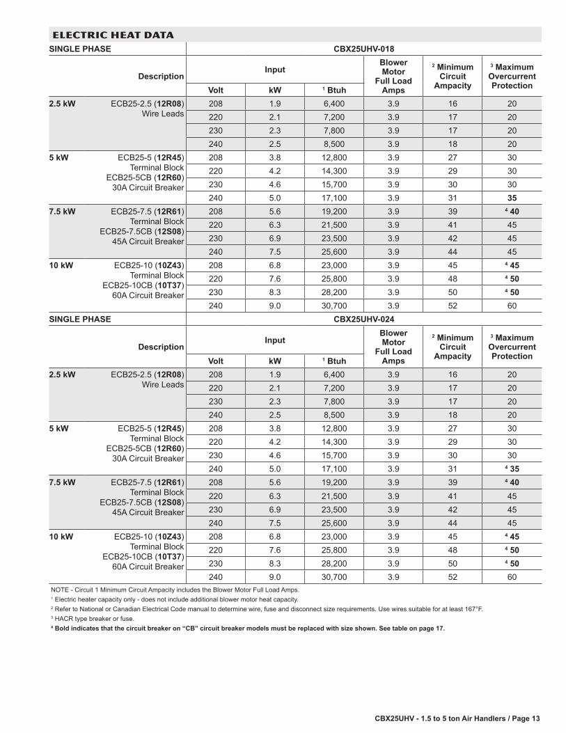
NOTE - Circuit 1 Minimum Circuit Ampacity includes the Blower Motor Full Load Amps.1 Electric heater capacity only - does not include additional blower motor heat capacity.2 Refer to National or Canadian Electrical Code manual to determine wire, fuse and disconnect size requirements. Use wires suitable for at least 167°F.3 HACR type breaker or fuse.4 Bold indicates that the circuit breaker on “CB” circuit breaker models must be replaced with size shown. See table on page 17.
240 15.0 51,200 3.9 28 52 4 35 60 83 90NOTE - Circuit 1 Minimum Circuit Ampacity includes the Blower Motor Full Load Amps.1 Electric heater capacity only - does not include additional blower motor heat capacity.2 Refer to National or Canadian Electrical Code manual to determine wire, fuse and disconnect size requirements. Use wires suitable for at least 167°F.3 HACR type breaker or fuse.4 Bold indicates that the circuit breaker on “CB” circuit breaker models must be replaced with size shown. See table on page 17.
NOTE - Circuit 1 Minimum Circuit Ampacity includes the Blower Motor Full Load Amps.1 Electric heater capacity only - does not include additional blower motor heat capacity.2 Refer to National or Canadian Electrical Code manual to determine wire, fuse and disconnect size requirements. Use wires suitable for at least 167°F.3 HACR type breaker or fuse.4 Bold indicates that the circuit breaker on “CB” circuit breaker models must be replaced with size shown. See table on page 17.
NOTE - Circuit 1 Minimum Circuit Ampacity includes the Blower Motor Full Load Amps.1 Electric heater capacity only - does not include additional blower motor heat capacity.2 Refer to National or Canadian Electrical Code manual to determine wire, fuse and disconnect size requirements. Use wires suitable for at least 167°F.3 HACR type breaker or fuse.4 Bold indicates that the circuit breaker on “CB” circuit breaker models must be replaced with size shown. See table on page 17.
CBX25UHV - 1.5 to 5 ton Air Handlers / Page 17
ELECTRIC HEAT DATASINGLE PHASE CBX25UHV-048, CBX25UHV-060
240 20.0 68,200 6.9 57 56 60 60 113 125NOTE - Circuit 1 Minimum Circuit Ampacity includes the Blower Motor Full Load Amps.1 Electric heater capacity only - does not include additional blower motor heat capacity.2 Refer to National or Canadian Electrical Code manual to determine wire, fuse and disconnect size requirements. Use wires suitable for at least 167°F.3 HACR type breaker or fuse.4 Bold indicates that the circuit breaker on “CB” circuit breaker models must be replaced with size shown. See table on page 17.
208/240V - 1 Phase 25 amp, 2 pole 41K1330 amp, 2 pole 17K7035 amp, 2 pole 72K0740 amp, 2 pole 49K1445 amp, 2 pole 17K7150 amp, 2 pole 41K1260 amp, 2 pole 17K72
CBX25UHV - 1.5 to 5 ton Air Handlers / Page 18
DIMENSIONS - UNIT - UPFLOW - INCHES (MM)
Dimension018 024 030 036 042 048-060
in. mm in. mm in. mm in. mm in. mm in. mmA 38 965 40-1/2 1029 43 1092 48 1219 48 1219 52-1/2 1334B 15 381 18-1/2 470 18-1/2 470 21-7/8 556 21-7/8 556 21-7/8 556C 22 559 22 559 22 559 22 559 26 660 26 660D 6 152 6 152 6 152 12-1/4 311 6-1/4 159 6-3/8 162E 11 279 14 357 16 406 18-7/8 479 17-7/8 454 15-1/4 387F 3-5/8 92 5-1/2 140 5-1/2 140 5-3/4 146 3-1/4 83 3-1/4 83G 3-5/8 92 5-1/2 140 5-1/2 140 5-3/4 146 4-5/8 117 6-3/8 162
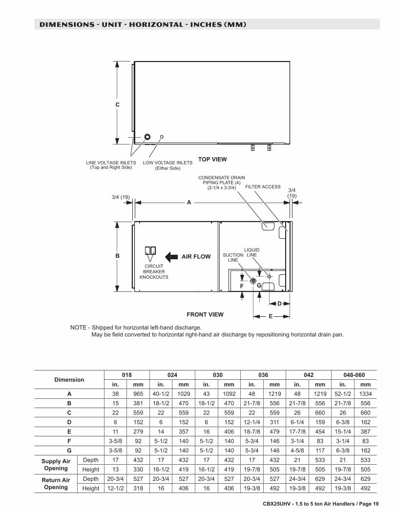
NOTE - Shipped for horizontal left-hand discharge. May be field converted to horizontal right-hand air discharge by repositioning horizontal drain pan.
CBX25UHV - 1.5 to 5 ton Air Handlers / Page 20
DIMENSIONS - ACCESSORIES - INCHES (MM)
ADJUSTABLE20 (508) to
25 (635)ALL UNITS
16(406)
6(152)
SIDE RETURN UNIT STAND(Upflow Only)
21-1/4(540)
INSTALLATION CLEARANCES WITH ELECTRIC HEATCabinet 0 inch (0 mm)To Plenum 0 inch (0 mm)To Outlet Duct within 3 feet (914 mm) 0 inch (0 mm)Floor 0 inch (0 mm)Service / Maintenance See Note #11 Front service access - 24 inches (610 mm) minimum.NOTE - If cabinet depth is more than 24 inches (610 mm), allow a minimum of the cabinet depth plus 2 inches (51 mm).